JP2007201208A - Semiconductor device and its manufacturing method - Google Patents
Semiconductor device and its manufacturing method Download PDFInfo
- Publication number
- JP2007201208A JP2007201208A JP2006018343A JP2006018343A JP2007201208A JP 2007201208 A JP2007201208 A JP 2007201208A JP 2006018343 A JP2006018343 A JP 2006018343A JP 2006018343 A JP2006018343 A JP 2006018343A JP 2007201208 A JP2007201208 A JP 2007201208A
- Authority
- JP
- Japan
- Prior art keywords
- film
- etching stopper
- insulating film
- wiring
- stopper film
- Prior art date
- Legal status (The legal status is an assumption and is not a legal conclusion. Google has not performed a legal analysis and makes no representation as to the accuracy of the status listed.)
- Granted
Links
Images


Classifications
-
- H—ELECTRICITY
- H01—ELECTRIC ELEMENTS
- H01L—SEMICONDUCTOR DEVICES NOT COVERED BY CLASS H10
- H01L23/00—Details of semiconductor or other solid state devices
- H01L23/52—Arrangements for conducting electric current within the device in operation from one component to another, i.e. interconnections, e.g. wires, lead frames
- H01L23/522—Arrangements for conducting electric current within the device in operation from one component to another, i.e. interconnections, e.g. wires, lead frames including external interconnections consisting of a multilayer structure of conductive and insulating layers inseparably formed on the semiconductor body
- H01L23/5222—Capacitive arrangements or effects of, or between wiring layers
- H01L23/5223—Capacitor integral with wiring layers
-
- H—ELECTRICITY
- H01—ELECTRIC ELEMENTS
- H01L—SEMICONDUCTOR DEVICES NOT COVERED BY CLASS H10
- H01L21/00—Processes or apparatus adapted for the manufacture or treatment of semiconductor or solid state devices or of parts thereof
- H01L21/70—Manufacture or treatment of devices consisting of a plurality of solid state components formed in or on a common substrate or of parts thereof; Manufacture of integrated circuit devices or of parts thereof
- H01L21/71—Manufacture of specific parts of devices defined in group H01L21/70
- H01L21/768—Applying interconnections to be used for carrying current between separate components within a device comprising conductors and dielectrics
- H01L21/76801—Applying interconnections to be used for carrying current between separate components within a device comprising conductors and dielectrics characterised by the formation and the after-treatment of the dielectrics, e.g. smoothing
- H01L21/76802—Applying interconnections to be used for carrying current between separate components within a device comprising conductors and dielectrics characterised by the formation and the after-treatment of the dielectrics, e.g. smoothing by forming openings in dielectrics
-
- H—ELECTRICITY
- H01—ELECTRIC ELEMENTS
- H01L—SEMICONDUCTOR DEVICES NOT COVERED BY CLASS H10
- H01L21/00—Processes or apparatus adapted for the manufacture or treatment of semiconductor or solid state devices or of parts thereof
- H01L21/70—Manufacture or treatment of devices consisting of a plurality of solid state components formed in or on a common substrate or of parts thereof; Manufacture of integrated circuit devices or of parts thereof
- H01L21/71—Manufacture of specific parts of devices defined in group H01L21/70
- H01L21/768—Applying interconnections to be used for carrying current between separate components within a device comprising conductors and dielectrics
- H01L21/76801—Applying interconnections to be used for carrying current between separate components within a device comprising conductors and dielectrics characterised by the formation and the after-treatment of the dielectrics, e.g. smoothing
- H01L21/76829—Applying interconnections to be used for carrying current between separate components within a device comprising conductors and dielectrics characterised by the formation and the after-treatment of the dielectrics, e.g. smoothing characterised by the formation of thin functional dielectric layers, e.g. dielectric etch-stop, barrier, capping or liner layers
- H01L21/76832—Multiple layers
-
- H—ELECTRICITY
- H01—ELECTRIC ELEMENTS
- H01L—SEMICONDUCTOR DEVICES NOT COVERED BY CLASS H10
- H01L21/00—Processes or apparatus adapted for the manufacture or treatment of semiconductor or solid state devices or of parts thereof
- H01L21/70—Manufacture or treatment of devices consisting of a plurality of solid state components formed in or on a common substrate or of parts thereof; Manufacture of integrated circuit devices or of parts thereof
- H01L21/71—Manufacture of specific parts of devices defined in group H01L21/70
- H01L21/768—Applying interconnections to be used for carrying current between separate components within a device comprising conductors and dielectrics
- H01L21/76801—Applying interconnections to be used for carrying current between separate components within a device comprising conductors and dielectrics characterised by the formation and the after-treatment of the dielectrics, e.g. smoothing
- H01L21/76829—Applying interconnections to be used for carrying current between separate components within a device comprising conductors and dielectrics characterised by the formation and the after-treatment of the dielectrics, e.g. smoothing characterised by the formation of thin functional dielectric layers, e.g. dielectric etch-stop, barrier, capping or liner layers
- H01L21/76834—Applying interconnections to be used for carrying current between separate components within a device comprising conductors and dielectrics characterised by the formation and the after-treatment of the dielectrics, e.g. smoothing characterised by the formation of thin functional dielectric layers, e.g. dielectric etch-stop, barrier, capping or liner layers formation of thin insulating films on the sidewalls or on top of conductors
-
- H—ELECTRICITY
- H01—ELECTRIC ELEMENTS
- H01L—SEMICONDUCTOR DEVICES NOT COVERED BY CLASS H10
- H01L2924/00—Indexing scheme for arrangements or methods for connecting or disconnecting semiconductor or solid-state bodies as covered by H01L24/00
- H01L2924/0001—Technical content checked by a classifier
- H01L2924/0002—Not covered by any one of groups H01L24/00, H01L24/00 and H01L2224/00
Abstract
Description
本発明は、半導体装置及びその製造方法に関し、特に、キャパシタを含む半導体装置及びその製造方法に関する。 The present invention relates to a semiconductor device and a manufacturing method thereof, and more particularly to a semiconductor device including a capacitor and a manufacturing method thereof.
一般に、移動体通信分野等に用いられる高周波アナログ集積回路においては、扱う信号の特性から高速動作可能な能動素子(トランジスタ等)に加えて、抵抗素子、キャパシタ、インダクタ等の受動素子が必要となる。また、動作速度の向上及び消費電力の低減のために、寄生容量及び寄生抵抗の低減が必要になる。寄生容量及び寄生抵抗の低減のために、金属−酸化物絶縁膜−半導体(MOS)構造のキャパシタよりも、金属−絶縁膜−金属(MIM)構造のキャパシタが利用される。 In general, a high-frequency analog integrated circuit used in the field of mobile communication requires a passive element such as a resistance element, a capacitor, and an inductor in addition to an active element (such as a transistor) capable of high-speed operation because of characteristics of a signal to be handled. . Further, in order to improve the operation speed and reduce the power consumption, it is necessary to reduce the parasitic capacitance and the parasitic resistance. In order to reduce parasitic capacitance and parasitic resistance, a capacitor having a metal-insulating film-metal (MIM) structure is used rather than a capacitor having a metal-oxide insulating film-semiconductor (MOS) structure.
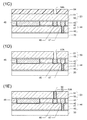
図7に、ダマシン法を用いて形成した配線と、MIM構造のキャパシタとを有する半導体装置の断面図を示す。図7に示した構造と類似した構造のMIM構造のキャパシタが下記の非特許文献1に開示されている。以下、図7に示した半導体装置の製造方法について説明する。 FIG. 7 shows a cross-sectional view of a semiconductor device having a wiring formed by using the damascene method and a capacitor having an MIM structure. A capacitor having an MIM structure similar to the structure shown in FIG. A method for manufacturing the semiconductor device shown in FIG. 7 will be described below.
層間絶縁膜100の上に、SiNからなるエッチングストッパ膜101及びSiO2からなる層間絶縁膜102を形成する。この2層に配線溝を形成し、この配線溝内に銅配線103を充填する。層間絶縁膜102の上に、銅の拡散防止及びエッチングストッパの機能を有するSiNからなるエッチングストッパ膜106を形成する。このエッチングストッパ膜106の上に、SiO2膜112を薄く成膜する。なお、このSiO2膜112は必須ではない。SiO2膜112の上面から層間絶縁膜100の上面まで達する凹部110を形成する。
On the interlayer
基板全面に、下部電極115AとなるTiN膜、キャパシタ誘電体膜116AとなるSiO2膜、上部電極117AとなるTiN膜、及び上部絶縁膜118AとなるSiN膜を順番に堆積させる。この4層は、凹部110の内面にも堆積する。下側のTiN膜からSiN膜までの4層を、下部電極115Aの形状にパターニングする。この際に、凹部110をアライメントマークとして用いる。層間絶縁膜102の上面は平坦であるため、その上にTiN膜を形成すると、下層の配線103の位置が検出できなくなる。このため、凹部110を形成し、アライメントマークとして用いる。
A TiN film to be the
次に、SiO2膜、上側のTiN膜、及びSiN膜を、上部電極117Aの形状にパターニングする。TiNからなる下部電極115A、SiO2からなるキャパシタ誘電体膜116A、TiNからなる上部電極117Aによりキャパシタ119が構成される。凹部110の内面上にも。TiN膜115B、SiO2膜116B、上側のTiN膜117B、及びSiN膜118Bが残る。
Next, the SiO 2 film, the upper TiN film, and the SiN film are patterned into the shape of the
下部電極115Aを形成する際に、下部電極115Aとは異なる場所にアライメントマークを形成しておく。このアライメントマークを用いて、上部電極117Aの形状にパターニングする際の位置合せが行われる。なお、上部電極と下部電極との位置合せ精度の許容範囲によっては、上部電極117Aの形状にパターニングする際にも、凹部110の段差をアライメントマークとして用いることが可能である。
When forming the
キャパシタ119を覆うように、層間絶縁膜120を形成し、表面の平坦化を行う。層間絶縁膜120にビアホール122A、122B及び122Cを形成する。ビアホール122Aは、上部電極117Aの脇を通過して下部電極115Aの上面を露出させる。ビアホール122Bは、上部絶縁膜118Aを貫通して上部電極117Aの上面を露出させる。ビアホール122Cは、SiO2膜112及びエッチングストッパ膜106を貫通して下層の配線103の上面を露出させる。
An
これらのビアホール122A、122B及び122Cの内面をバリアメタル膜で被覆した後、ビアホール内にタングステン(W)からなるプラグを充填する。層間絶縁膜120の上に、アルミニウム(Al)等からなる配線125A、125B及び125Cを形成する。配線125A、125B及び125Cは、それぞれビアホール122A、122B及び122C内に充填されたプラグに接続される。
After the inner surfaces of these via
上記製造方法では、凹部110を形成する工程、下部電極115Aのパターニングを行う工程、及び上部電極117Aのパターニングを行う工程において、それぞれ1回ずつフォトリソグラフィを行う必要がある。すなわち、キャパシタ119を形成しない場合に比べて、3回のフォトリソグラフィ工程が新たに追加される。
In the manufacturing method described above, it is necessary to perform photolithography once each in the step of forming the
図8A〜図8Dを参照して、下記の特許文献1に開示されたMIM構造のキャパシタの製造方法について説明する。 With reference to FIGS. 8A to 8D, a method for manufacturing a capacitor having an MIM structure disclosed in Patent Document 1 below will be described.
図8Aに示すように、層間絶縁膜150に形成された配線溝内に配線152が充填され、キャパシタ用の凹部内に下部電極151が充填されている。層間絶縁膜150、下部電極151、及び配線152の上に、エッチングストッパ膜155を形成する。さらにその上に、層間絶縁膜156を形成する。層間絶縁膜156に、キャパシタ用の凹部156Aを形成する。凹部156Aは、平面視において下部電極151と部分的に重なる。
As shown in FIG. 8A, a
全面を覆うようにバリアメタル膜を形成し、さらに、導電膜を堆積させる。層間絶縁膜156の上面が露出するまで化学機械研磨(CMP)を行う。図8Bに示すように、凹部156A内に残った導電膜により、上部電極158が形成される。
A barrier metal film is formed so as to cover the entire surface, and a conductive film is further deposited. Chemical mechanical polishing (CMP) is performed until the upper surface of the interlayer
図8Cに示すように、層間絶縁膜156及び上部電極158の上に、エッチングストッパ膜160を形成し、さらにその上に、層間絶縁膜161を形成する。
As shown in FIG. 8C, an
図8Dに示すように、層間絶縁膜161及びエッチングストッパ膜160に、凹部161Bを形成すると共に、凹部161Bの底面から配線152の上面まで達するビアホール156Bを形成する。平面視において、凹部161Bは上部電極158及び下層の配線152と重なる。凹部161の底面の一部に上部電極158が露出し、ビアホール156Bの底面に配線152の上面が露出する。
As shown in FIG. 8D, a
凹部161B及びビアホール156Bの内面をバリアメタル膜で覆い、内部に導電部材163を充填する。下部電極151、上部電極158、及び両者の間に配置されたエッチングストッパ膜155によりキャパシタが構成される。上部電極158は、導電部材163を介して、下部電極151と同一の層内の配線152に接続される。
The inner surfaces of the
図8A〜図8Dに示した方法では、キャパシタを形成するために、図8Aに示した凹部156Aの形成、この凹部156A内への導電膜の充填、及びCMPの工程が新たに追加される。
In the method shown in FIGS. 8A to 8D, in order to form a capacitor, the steps of forming the
本発明の目的は、キャパシタを形成するために必要となる追加工程数がより少ない半導体装置及びその製造方法を提供することである。 An object of the present invention is to provide a semiconductor device that requires fewer additional steps to form a capacitor and a method for manufacturing the same.
本発明の一観点によると、半導体基板の上に形成された第1の層間絶縁膜と、前記第1の層間絶縁膜に形成された第1のキャパシタ用凹部及び配線溝と、前記第1のキャパシタ用凹部内に充填された下部電極と、前記配線溝内に充填された第1の配線と、前記第1の層間絶縁膜の上に配置された第1のエッチングストッパ膜と、前記第1のエッチングストッパ膜の上に配置され、該第1のエッチングストッパ膜とはエッチング耐性の異なる絶縁材料で形成されたビア層絶縁膜と、前記ビア層絶縁膜及び前記第1のエッチングストッパ膜を貫通し、前記第1の配線の上面まで達する第1のビアホールと、前記第1のビアホール内に充填された導電性の第1のプラグと、前記ビア層絶縁膜に形成され、前記第1のエッチングストッパ膜まで達し、平面視において前記下部電極と少なくとも部分的に重なる第2のキャパシタ用凹部と、前記第2のキャパシタ用凹部の底面と側面、及び該第2のキャパシタ用凹部に連続する前記ビア層絶縁膜の上面の一部を覆うように配置された上部電極であって、前記第1のエッチングストッパ膜をキャパシタ誘電体膜とし、前記下部電極とともにキャパシタを構成する上部電極と、前記ビア層絶縁膜の上に形成され、前記第1のプラグに接続された第2の配線とを有する半導体装置が提供される。 According to one aspect of the present invention, a first interlayer insulating film formed on a semiconductor substrate, a first capacitor recess and a wiring groove formed in the first interlayer insulating film, and the first A lower electrode filled in the capacitor recess, a first wiring filled in the wiring trench, a first etching stopper film disposed on the first interlayer insulating film, and the first A via layer insulating film formed of an insulating material different in etching resistance from the first etching stopper film, and penetrating through the via layer insulating film and the first etching stopper film. A first via hole reaching the upper surface of the first wiring; a conductive first plug filled in the first via hole; and the via layer insulating film; To the stopper film, A second capacitor recess that at least partially overlaps the lower electrode in plan view, a bottom surface and a side surface of the second capacitor recess, and an upper surface of the via layer insulating film that is continuous with the second capacitor recess An upper electrode disposed so as to cover a part of the upper electrode, wherein the first etching stopper film is a capacitor dielectric film, and the upper electrode constituting the capacitor together with the lower electrode; and the via layer insulating film A semiconductor device having a second wiring formed and connected to the first plug is provided.
本発明の他の観点によると、(a)半導体基板の上に、第1の層間絶縁膜を形成する工程と、(b)前記第1の層間絶縁膜に、第1のキャパシタ用凹部及び配線溝を形成する工程と、(c)前記第1のキャパシタ用凹部内及び前記配線溝内に、それぞれ下部電極及び第1の配線を充填する工程と、(d)前記第1の層間絶縁膜、前記下部電極、及び前記第1の配線の上面を第1のエッチングストッパ膜で覆う工程と、(e)前記第1のエッチングストッパ膜の上に、該第1のエッチングストッパ膜とはエッチング耐性の異なる絶縁材料からなるビア層絶縁膜を形成する工程と、(f)前記ビア層絶縁膜及び前記第1のエッチングストッパ膜を貫通し、前記第1の配線の一部を露出させる第1のビアホールを形成する工程と、(g)前記第1のビアホール内に、導電性の第1のプラグを充填する工程と、(h)前記ビア層絶縁膜に、平面視において前記下部電極と少なくとも部分的に重なる第2のキャパシタ用凹部を形成し、その底面に前記第1のエッチングストッパ膜の少なくとも一部を残す工程と、(i)前記第2のキャパシタ用凹部の内面、前記第1のプラグの上面、及び前記ビア層絶縁膜の上面を覆うように、導電膜を形成する工程と、(j)前記導電膜をパターニングすることにより、前記第2のキャパシタ用凹部内に上部電極を残すと共に、前記第1のプラグに接続された第2の配線を残す工程とを有する半導体装置の製造方法が提供される。 According to another aspect of the present invention, (a) a step of forming a first interlayer insulating film on a semiconductor substrate, and (b) a first capacitor recess and a wiring on the first interlayer insulating film. Forming a groove; (c) filling the first capacitor recess and the wiring groove with a lower electrode and a first wiring, respectively; (d) the first interlayer insulating film; A step of covering an upper surface of the lower electrode and the first wiring with a first etching stopper film; and (e) an etching resistance of the first etching stopper film on the first etching stopper film. A step of forming a via layer insulating film made of a different insulating material; and (f) a first via hole that penetrates the via layer insulating film and the first etching stopper film and exposes a part of the first wiring. (G) the first step Filling the first hole with a conductive first plug, and (h) forming a second capacitor recess at least partially overlapping the lower electrode in plan view in the via layer insulating film, Leaving at least part of the first etching stopper film on the bottom surface; and (i) covering the inner surface of the second capacitor recess, the upper surface of the first plug, and the upper surface of the via layer insulating film. Forming a conductive film; and (j) patterning the conductive film to leave an upper electrode in the second capacitor recess and to connect a second wiring connected to the first plug. And a method for manufacturing a semiconductor device.
キャパシタの下部電極は、同一層内の配線と同一工程で形成される。上部電極は、第2の配線と同一工程で形成される。このため、第2のキャパシタ用凹部を形成するための工程を新たに追加するのみで、キャパシタを形成することができる。 The lower electrode of the capacitor is formed in the same process as the wiring in the same layer. The upper electrode is formed in the same process as the second wiring. Therefore, the capacitor can be formed only by newly adding a process for forming the second capacitor recess.
図1A〜図1Jを参照して、第1の実施例による半導体装置の製造方法について説明する。 A method of manufacturing a semiconductor device according to the first embodiment will be described with reference to FIGS. 1A to 1J.
図1Aに示すように、シリコンからなる半導体基板1の表層部に、シャロートレンチアイソレーション(STI)構造の素子分離絶縁膜2が形成されている。素子分離絶縁膜2により画定された活性領域内にMOSFET3が形成されている。半導体基板1の表面及びMOSFET3を覆うように、SiNからなるエッチングストッパ膜4が形成され、その上にフォスフォシリケートガラス(PSG)等からなる1層目の層間絶縁膜5が形成されている。1層目の層間絶縁膜5及びエッチングストッパ膜4を貫通するビアホール6及び7が形成され、その内部に、それぞれW等からなるプラグ8及び9が充填されている。プラグ8及び9は、それぞれMOSFET3のソース領域及びドレイン領域に接続される。なお、ビアホール6及び7の内面は、TiN等からなるバリアメタル膜で被覆されている。
As shown in FIG. 1A, an element
1層目の層間絶縁膜5の上に、SiC等からなるエッチングストッパ膜10、SiOC等からなる絶縁膜11、及びSiO2からなるキャップ膜12の3層からなる2層目の層間絶縁膜13が形成されている。層間絶縁膜13に、複数の配線溝15が形成されている。配線溝15の内面がTa等からなるバリアメタル膜で覆われ、内部が、銅からなる導電部材16で埋め込まれている。配線溝15内の導電部材16が1層目の配線を構成する。配線溝15及び導電部材16は、シングルダマシン法により形成される。
On the first
2層目の層間絶縁膜13の上に、SiC等からなるエッチングストッパ膜20、SiOC等からなる絶縁膜21、及びSiO2からなるキャップ膜22の3層からなる3層目の層間絶縁膜23が形成されている。層間絶縁膜23に、複数の配線溝25及びビアホール26が形成されている。配線溝25及びビアホール26の内面がTa等からなるバリアメタル膜で覆われ、内部が、銅からなる導電部材28で埋め込まれている。配線溝25内の導電部材28が配線を構成し、ビアホール26内の導電部材28が上下の配線を接続する層間接続部を構成する。配線溝25、ビアホール26、及び導電部材28は、デュアルダマシン法により形成される。
On the second
3層目の層間絶縁膜23の上に、3層目の配線構造と同様のデュアルダマシン法で形成された複数の配線層30が配置されている。
A plurality of wiring layers 30 formed by the dual damascene method similar to the third layer wiring structure are arranged on the third
配線層30の上に、4層構造の層間絶縁膜44を形成する。層間絶縁膜44は、下地表面とはエッチング耐性の異なる絶縁材料、例えばSiNからなる厚さ50nmのエッチングストッパ膜40、エッチングストッパ膜40とはエッチング耐性の異なる絶縁材料、例えばSiO2からなる厚さ600nmのビア層絶縁膜41、ビア層絶縁膜41とはエッチング耐性の異なる絶縁材料、例えばSiNからなる厚さ50nmのエッチグストッパ膜42、及びエッチングストッパ膜42とはエッチング耐性の異なる絶縁材料、例えばSiO2からなる厚さ350nmの配線層絶縁膜43がこの順番に積層された構造を有する。これらの膜は、例えば化学気相成長(CVD)等により堆積される。
An interlayer insulating
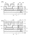
図1Bに示すように、層間絶縁膜44に、デュアルダマシン法を用いて配線を形成する。図1B〜図1Jにおいては、配線層30よりも上方の積層構造のみを示す。以下、デュアルダマシン法を用いた配線の形成方法について説明する。
As shown in FIG. 1B, wiring is formed in the
まず、配線層絶縁膜43の上面からビア層絶縁膜41の底面まで達するビアホール41Cを形成する。次に、ビア層絶縁膜41の上面まで達する配線溝43A、43C、及びキャパシタ用凹部43Bを形成する。配線溝43Cは、ビアホール41Cが形成された位置を通過する。配線溝形成のために配線層絶縁膜43をエッチングする時には、ビアホール41C内の下方の一部に樹脂製の保護部材を充填しておき、その底面に露出したエッチングストッパ膜40を保護する。配線層絶縁膜43のエッチング後、この保護部材と、エッチングマスクとして用いたレジスト膜とを除去する。さらに、配線溝43A、43C、及びキャパシタ用凹部43Bの底面に露出しているエッチングストッパ膜42、及びビアホール41Cの底面に露出しているエッチングストッパ膜40を除去する。
First, a via
露出した全面を覆うように、Ta等からなる厚さ30nmのバリアメタル膜を形成する。さらに、銅からなるシード膜をスパッタリングにより形成した後、銅を電解めっきすることにより、導電膜を形成する。配線層絶縁膜43の上面が露出するまでCMPを行う。これにより、配線溝43A内に銅配線46が残り、配線溝43C及びビアホール41C内に銅配線47が残り、キャパシタ用凹部43B内に銅からなる下部電極45が残る。配線47は、ビアホール41C内に充填されプラグを経由して下層の配線に接続される。ビアホール41C内のプラグは、配線47と一体化される。なお、下部電極45、配線46、47を、銅を主成分とする合金、Al、またはAlにCuを0.5〜1.0重量%程度添加したCu添加Al等で形成してもよい。
A barrier metal film made of Ta or the like and having a thickness of 30 nm is formed so as to cover the entire exposed surface. Furthermore, after forming a seed film made of copper by sputtering, copper is electroplated to form a conductive film. CMP is performed until the upper surface of the wiring
下部電極45等をCu、Cuを主成分とする合金等で形成する場合には、バリアメタル膜として、Ta、TaN、TiN等を用いる。下部電極45等をAl、Cu添加Al等で形成する場合には、バリアメタル膜としてTiNを用いる。また、絶縁膜とTiN膜との間、及びAl膜とTiN膜との間に、密着向上を図るためにTi膜を配置してもよい。
When the
図1Cに示すように、層間絶縁膜44、下部電極45、配線46及び47を覆うように、エッチングストッパ膜50とビア層絶縁膜51との2層構造の層間絶縁膜53を、化学気相成長(CVD)により形成する。エッチングストッパ膜50は、その下の配線層絶縁膜43とはエッチング耐性の異なる絶縁材料、例えばSiNで形成され、その厚さは70nmである。なお、エッチングストッパ膜50は、Cuの拡散防止機能を併せ持つ。ビア層絶縁膜51は、エッチングストッパ膜50とはエッチング耐性の異なる絶縁材料、例えばSiO2で形成され、その厚さは1000nmである。なお、ビア層絶縁膜51を1000nmよりもやや厚く成膜し、CMPを行って表面を平坦化してもよい。
As shown in FIG. 1C, an
層間絶縁膜53の上に、レジスト膜54を形成する。露光及び現像を行うことにより、レジスト膜54に開口54Aを形成する。開口54Aは、平面視において、下層の配線46に内包され、その平面形状の寸法は、0.5〜0.7μm程度である。レジスト膜54をマスクとして、CF系ガスを用いたプラズマエッチングにより、ビア層絶縁膜51をエッチングする。O2を含んだプラズマアッシングによりレジスト膜54を除去する。その後、ビアホール51Aの底面に露出しているエッチングストッパ膜50を、CHF系ガスを用いたプラズマエッチングにより除去する。
A resist
図1Dに示すように、層間絶縁膜53を貫通するビアホール51Aが形成され、その底面に配線46の上面が露出する。ビアホール51Aは、シングルダマシン構造を有する。
As shown in FIG. 1D, a via
図1Eに示す状態までの工程を説明する。ビアホール51Aの内面及びビア層絶縁膜51の上面を覆うように、TiNからなる厚さ50nmの接着層をスパッタリングにより形成する。次に、Wからなる厚さ350nmの導電膜をCVDにより堆積させる。この導電膜により、ビアホール51A内が完全に埋め尽くされる。ビア層絶縁膜51の上面が露出するまでCMPを行う。これにより、ビアホール51Aの内面を覆うTiNからなる密着層55、及び内部を充填するWからなるプラグ56が残る。なお、密着層55を、WN、WSiN等で形成してもよい。
Processes up to the state shown in FIG. 1E will be described. An adhesion layer made of TiN and having a thickness of 50 nm is formed by sputtering so as to cover the inner surface of the via
図1Fに示すように、層間絶縁膜53の上にレジスト膜59を形成し、露光及び現像を行って開口59Bを形成する。開口59Bは、平面視において、下部電極45に内包される。なお、開口59Bと下部電極45とが部分的に重なるように両者を配置してもよい。また、開口59Bの平面形状の寸法は、ビアホール51Aの平面形状の寸法よりも大きい。例えば、開口59Bの平面形状は長方形であり、その短辺及び長辺の長さは、例えばそれぞれ3〜5μm及び10μm程度である。
As shown in FIG. 1F, a resist
レジスト膜59をマスクとして、ビア層絶縁膜51をエッチングし、エッチングストッパ膜50を露出させる。ビア層絶縁膜51のエッチングは、例えば、CF系ガスを用いたプラズマエッチングにより行うことができる。ビア層絶縁膜51のエッチング後、O2ガスを用いたプラズマアッシングによりレジスト膜59を除去する。
Using the resist
図1Gに示すように、ビア層絶縁膜51に、キャパシタ用凹部51Bが形成される。キャパシタ用凹部51Bは、平面視において、下部電極45に内包される。また、平面視におけるキャパシタ用凹部51Bの面積は、ビアホール51Aの面積よりも大きい。
As shown in FIG. 1G, a
エッチングストッパ膜50のエッチング速度に対するビア層絶縁膜51のエッチング速度の比(エッチング選択比)、及びビア層絶縁膜51のエッチング時のオーバエッチング量により、キャパシタ用凹部51Bの底面に露出したエッチングストッパ膜50の厚さが決定される。例えば、エッチング選択比が10であり、オーバエッチング量を30%とすると、厚さ1000nmのビア層絶縁膜51をエッチングする際に、エッチングストッパ膜50の厚さが30nmだけ目減りする。成膜時のエッチングストッパ膜50の厚さを70nmに設定したため、キャパシタ用凹部51Bの底面に露出したエッチングストッパ膜50の厚さは40nmになる。
The etching stopper exposed on the bottom surface of the
図1Hに示す状態までの工程を説明する。キャパシタ用凹部51Bの内面、及びビア層絶縁膜51の上面を覆うように、TiNからなる厚さ50nmのバリアメタル膜60、AlCu合金からなる厚さ1000nmの導電膜61、及びTiNからなる厚さ50nmのバリアメタル膜62の3層をスパッタリングにより形成する。なお、導電膜61を、AlCu合金以外に、Alまたは、Alを主成分とする合金で形成してもよい。バリアメタル膜62の上に、レジスト膜を形成し、露光及び現像を行うことにより、レジストパターン65を形成する。レジストパターン65は、層間絶縁膜53の上に形成する配線、及びキャパシタの上部電極に対応する領域を覆う。レジストパターン65をマスクとして、バリアメタル膜62、導電膜61、及びバリアメタル膜60の3層をエッチングする。
Processes up to the state shown in FIG. 1H will be described. A 50 nm thick
図1Iに示すように、層間絶縁膜53の上に、3層構造を有する配線63A、パッド63C、及び上部電極63Bが残る。これらはすべて同一の積層構造を有する。上部電極63Bは、キャパシタ用凹部51Bの内面、及びそれに隣接する領域の層間絶縁膜53の上面を覆う。下部電極45と上部電極63Bとが、エッチングストッパ膜50を介して対向し、エッチングストッパ膜50をキャパシタ誘電体膜とするキャパシタ64が構成される。配線63Aは、プラグ56を介して下層の配線46に接続される。
As shown in FIG. 1I, a
なお、上部電極63B等を、上側から順番にTiN/Ti/Al/TiN/Tiが積層された5層構造、またはTiN/Ti/Al/TiNの4層構造にしてもよい。Ti膜は、密着性を高める機能を有する。
Note that the
図1Jに示すように、上部電極63B、配線63A、及びパッド63Cを覆うように、層間絶縁膜53の上に、SiO2からなる厚さ1000nmのカバー膜70、及びSiNからなる厚さ500nmのカバー膜71を、プラズマ励起型CVDにより形成する。カバー膜70及び71に開口72を形成することにより、パッド63Cを露出させる。
As shown in FIG. 1J, a 1000 nm
図2に、キャパシタ64及び配線63Aの平面図を示す。図2の一点鎖線A1−A1における断面図が、図1A〜図1Jに対応する。上部電極63B用のキャパシタ用凹部51Bが下部電極45に内包される。下部電極45に、下部電極45と同一層内に配置された引出し用配線45Lが接続されている。配線45Lは、図1Jに示した配線層絶縁膜43に形成された引出し線用配線溝内に充填されている。上部電極63Bが、ビアホールH1内を経由して、下部電極45と同一層内に配置された配線45Mに接続されている。
FIG. 2 is a plan view of the
上記第1の実施例では、図1Fに示したレジスト膜59を形成する工程、レジスト膜59に開口59Bを形成する工程、図1Gに示したキャパシタ用凹部51Bを形成する工程、及びレジスト膜59を除去する工程が、キャパシタ64を形成するために新たに追加される。図1Iに示した上部電極63Bは、同一層内の配線63A、パッド63Cの形成と同時に行われる。このため、キャパシタ形成のために新たに必要となる工程数の増加を抑制することができる。
In the first embodiment, the step of forming the resist
上記第1の実施例では、図1Gに示したキャパシタ用凹部51Bを形成する前に、プラグ56用のビアホール51Aを形成した。両者を形成する順番を逆にすると、ビアホール51Aの底面のエッチングストッパ膜50を除去するときに、キャパシタ用凹部51Bの底面のエッチングストッパ膜50が除去されないように、レジスト膜等でマスクする必要がある。第1の実施例のように、キャパシタ用凹部51Bをビアホール51Aよりも後に形成することにより、キャパシタ用凹部51Bの底面をマスクするための工程増を回避することができる。なお、第1の実施例では、図1Fに示したレジスト膜59を、O2ガスを含むプラズマアッシングにより除去する際に、TiNからなる密着層55及びWからなるプラグ56の上面が酸素プラズマに晒される。ただし、TiN及びWは、酸化され難い材料であるため、その表面が酸素プラズマに晒されても、プラグ56とその上の配線63Aとの間の接触抵抗を十分低く維持することができる。
In the first embodiment, the via
また、上記第1の実施例では、上部電極63Bを収容するキャパシタ用凹部51Bが、平面視において下部電極45に内包されている。両者の一部分同士が重なる場合には、両者の位置ずれが生じた場合に、上部電極63Bと下部電極45とが対向する領域の面積が変動してしまう。キャパシタ用凹部51Bが下部電極45に内包されている場合には、位置ずれが生じても、それが許容範囲内であれば、上部電極63Bと下部電極45とが対向するの領域の面積を一定に保つことができる。これにより、所望のキャパシタンスを維持することができる。
In the first embodiment, the
図3及び図4に、それぞれ第2の実施例による半導体装置の断面図及び平面図を示す。図3は、図4の一点鎖線A3−A3における断面図である。以下、図1A〜図1J、及び図2に示した第1の実施例による半導体装置との相違点に着目して説明する。 3 and 4 are a sectional view and a plan view of the semiconductor device according to the second embodiment, respectively. 3 is a cross-sectional view taken along one-dot chain line A3-A3 in FIG. The following description will be given focusing on the differences from the semiconductor device according to the first embodiment shown in FIGS. 1A to 1J and FIG.
層間絶縁膜44の下層の層間絶縁膜34に形成された配線溝32A内に、銅からなる配線35が充填されている。配線溝32Aの内面はバリアメタル膜で覆われている。銅配線35は、デュアルダマシン法で形成される。
A
ビア層絶縁膜41及びエッチングストッパ膜40に、キャパシタ用凹部43Bの底面から配線35の上面まで達するビアホール41Bが形成されている。キャパシタ用凹部43Bの内面を覆うバリアメタル膜がビアホール41Bの内面まで連続的に覆い、下部電極45がビアホール41B内にも充填されている。
A via
層間絶縁膜44の他の領域に、配線溝43D、43E及びビアホール41Dが形成されている。ビアホール41Dは、配線溝43Dの底面から配線35の上面まで達する。配線溝43D及びビアホール41Dの内面がバリアメタル膜で覆われ、内部が導電部材49で埋め尽くされている。配線溝43Eの内面がバリアメタル膜で覆われ、内部が配線48で埋め尽くされている。キャパシタ用凹部43Bとビアホール41B、及び配線溝43Dとビアホール41Dは、図1Bに示した配線溝43Cとビアホール41Cの形成工程と同一の工程で形成される。配線溝43D及びビアホール41D内に充填される導電部材49は、下部電極45の形成と同一の工程で形成される。
In other regions of the
層間絶縁膜53の上に堆積している上部電極63Bの底面から、配線48の上面まで達するビアホール51Dが、層間絶縁膜53に形成されている。ビアホール51Dの内面がバリアメタル膜で覆われ、内部にプラグ58が充填されている。言い換えれば、上部電極63Bが、プラグ58の上まで達している。プラグ58は、上部電極63Bと配線48とを接続する。この構造は、図1Jにおいて、上部電極63Bと配線63Aとを相互に接続した構造と同じである。
A via
第2の実施例においては、図4に示すように、平面視において上部電極63Bを収容するキャパシタ用凹部51Bの外周線が、下部電極45の外周線よりも外側に配置されている。以下、このような平面配置を採用することの効果について、図5A及び図5Bを参照しながら説明する。
In the second embodiment, as shown in FIG. 4, the outer circumferential line of the
図5Aに、平面視において、キャパシタ用凹部51Bが下部電極45に内包される場合の断面図を示す。ビア層絶縁膜51をエッチングする際に、形成されるキャパシタ用凹部51Bの側壁を保護する目的で、エッチングガスに堆積性ガス(デポガス)を混合する。堆積性ガスによって生成される副生成物が側壁を保護する。例えば、エッチングガスとしてCF4、C4F8等を用い、堆積性ガスとしてCO等を用いる。
FIG. 5A shows a cross-sectional view when the
ビアホール51Aのように、平面形状の寸法が小さい場合には、その側壁を保護する目的が達成される。ところが、キャパシタ用凹部51Bのように平面形状の寸法が大きい場合には、堆積性ガスによる副生成物が、広い底面をも保護し、底面のエッチング速度が低下する。ところが、底面の外周近傍には副生成物が付着しにくいため、外周近傍のエッチング速度が中央のエッチング速度よりも速くなる。このため、図5Aに示したように、キャパシタ用凹部51Bの底面の外周近傍のエッチングストッパ膜50が過剰にエッチングされ、下部電極45が露出してしまう場合がある。下部電極45が露出すると、キャパシタの下部電極45と、キャパシタ用凹部51Bの内面を覆う上部電極とが短絡してしまう。
When the dimension of the planar shape is small like the via
図5Bに、第2の実施例による構成を採用した場合の断面図を示す。キャパシタ用凹部51Bの外周線が下部電極45の外周線よりも外側に配置されているため、キャパシタ用凹部51Bの外周線近傍においてエッチングストッパ膜50が過剰にエッチングされたとしても、下部電極45が露出することはない。従って、キャパシタの下部電極と上部電極との短絡を防止することができる。
FIG. 5B shows a cross-sectional view when the configuration according to the second embodiment is adopted. Since the outer peripheral line of the
第2の実施例において、図2に示した第1の実施例のように、下部電極45と同一層内に、下部電極45に接続された配線45Lを配置すると、平面視において、キャパシタ用凹部51Bの外周線が配線45Lと交差してしまう。エッチングストッパ膜50が過剰にエッチングされると、この交差箇所で、上部電極と配線45Lとの短絡が発生してしまう。第2の実施例では、下部電極45が、それよりも下層の層間絶縁膜34内に埋め込まれた配線35を介して、他の電子回路要素に接続される。このため、下部電極45の引出し配線35と、キャパシタ用凹部51Bの内面を覆う上部電極63Bとの短絡を防止することができる。
In the second embodiment, when the
さらに、キャパシタ用凹部51Bと下部電極45との位置ずれが生じた場合でも、そのずれ量が許容範囲内であれば、下部電極45と上部電極64Bとが対向する領域の面積を一定に維持することができる。これにより、所望のキャパシタンスを得ることができる。
Furthermore, even when a positional deviation between the
次に、図6A〜図6Cを参照して、第3の実施例による半導体装置及びその製造方法について説明する。 Next, with reference to FIGS. 6A to 6C, a semiconductor device and a manufacturing method thereof according to the third embodiment will be described.
図6Aに、図1Fに示した第1の実施例の製造途中段階に対応する断面図を示す。第1の実施例では、層間絶縁膜53がエッチングストッパ膜50とビア層絶縁膜51との2層で構成されていたが、第3の実施例では、エッチングストッパ膜50とビア層絶縁膜51との間に、第2層目のエッチングストッパ膜80及び第3層目のエッチングストッパ膜81が配置されている。第2層目のエッチングストッパ膜80は、第1層目のエッチングストッパ膜50及び第3層目のエッチングストッパ膜81のいずれとも異なるエッチング耐性を有する。第3層目のエッチングストッパ膜81は、その上のビア層絶縁膜51とは異なるエッチング耐性を有する。例えば、第1層目のエッチングストッパ膜50と第3層目のエッチングストッパ膜81とがSiNで形成され、第2層目のエッチングストッパ膜80とビア層絶縁膜51とがSiO2で形成される。第1層目のエッチングストッパ膜50及び第2層目エッチングストッパ膜80の厚さは、共に30nmである。第3層目のエッチングストッパ膜81の厚さは70nmである。
FIG. 6A shows a cross-sectional view corresponding to the intermediate stage of manufacture of the first embodiment shown in FIG. 1F. In the first embodiment, the
レジスト膜59をマスクとして、第3層目のエッチングストッパ膜81に対してビア層絶縁膜51を選択的にエッチングできる条件、例えばCF系ガスを用いたプラズマエッチングにより、ビア層絶縁膜51をエッチングする。その後、レジスト膜59を、O2ガスを用いたプラズマアッシングにより除去する。
Using the resist
図6Bに示すように、ビア層絶縁膜51にキャパシタ用凹部51Bが形成される。その底面には、第3層目のエッチングストッパ膜81が露出する。次に、第2層目のエッチングストッパ膜80に対して第3層目のエッチングストッパ膜81を選択的にエッチングできる条件、例えばCHF系ガスを用いたプラズマエッチングにより、キャパシタ用凹部51Bの底面に露出した第3層目のエッチングストッパ膜81をエッチングする。第3層目のエッチングストッパ膜81はビア層絶縁膜51に比べて十分薄いため、そのオーバエッチング量は、ビア層絶縁膜51をエッチングするときのオーバエッチング量に比べて少なくすることができる。このため、第2層目のエッチングストッパ膜80に与えるダメージを軽減することができる。
As shown in FIG. 6B, a
次に、第1層目のエッチングストッパ膜50に対して第2層目のエッチングストッパ膜80を選択的にエッチングできる条件、例えばフッ酸を用いたウェットエッチングにより、キャパシタ用凹部51Bの底面に露出している第2層目のエッチングストッパ膜80をエッチングする。
Next, the second
図6Cに示すように、キャパシタ用凹部51Bの底面に第1層目のエッチングストッパ膜50が露出する。第2層目のエッチングストッパ膜80を、ウェットエッチングを用いて除去するため、第1層目のエッチングストッパ膜50が受けるダメージを軽減するとともに、その膜厚を高精度に制御することが可能になる。
As shown in FIG. 6C, the first-layer
上記実施例では、エッチングストッパ膜としてSiNを用いたが、その他に、SiC、SiCN、SiON等を用いることができる。これらの材料は、Cuの拡散防止機能も併せ持つ。なお、Cuの拡散防止機能を高めるためには、SiON中のOを少なくすることが好ましい。また、上記実施例では、ビア層絶縁膜、配線層絶縁膜としてSiO2を用いたが、その他に、SiOC、低誘電率有機絶縁材料等を用いてもよい。 In the above embodiment, SiN is used as the etching stopper film, but SiC, SiCN, SiON, or the like can be used in addition. These materials also have a Cu diffusion preventing function. In order to enhance the Cu diffusion preventing function, it is preferable to reduce O in SiON. In the above embodiment, SiO 2 is used as the via layer insulating film and the wiring layer insulating film. However, SiOC, a low dielectric constant organic insulating material, or the like may be used.
以上実施例に沿って本発明を説明したが、本発明はこれらに制限されるものではない。例えば、種々の変更、改良、組み合わせ等が可能なことは当業者に自明であろう。 Although the present invention has been described with reference to the embodiments, the present invention is not limited thereto. It will be apparent to those skilled in the art that various modifications, improvements, combinations, and the like can be made.
上記実施例から、以下の付記に示す発明が導出される。 The invention shown in the following supplementary notes is derived from the above embodiments.
(付記1)
半導体基板の上に形成された第1の層間絶縁膜と、
前記第1の層間絶縁膜に形成された第1のキャパシタ用凹部及び配線溝と、
前記第1のキャパシタ用凹部内に充填された下部電極と、
前記配線溝内に充填された第1の配線と、
前記第1の層間絶縁膜の上に配置された第1のエッチングストッパ膜と、
前記第1のエッチングストッパ膜の上に配置され、該第1のエッチングストッパ膜とはエッチング耐性の異なる絶縁材料で形成されたビア層絶縁膜と、
前記ビア層絶縁膜及び前記第1のエッチングストッパ膜を貫通し、前記第1の配線の上面まで達する第1のビアホールと、
前記第1のビアホール内に充填された導電性の第1のプラグと、
前記ビア層絶縁膜に形成され、前記第1のエッチングストッパ膜まで達し、平面視において前記下部電極と少なくとも部分的に重なる第2のキャパシタ用凹部と、
前記第2のキャパシタ用凹部の底面と側面、及び該第2のキャパシタ用凹部に連続する前記ビア層絶縁膜の上面の一部を覆うように配置された上部電極であって、前記第1のエッチングストッパ膜をキャパシタ誘電体膜とし、前記下部電極とともにキャパシタを構成する上部電極と、
前記ビア層絶縁膜の上に形成され、前記第1のプラグに接続された第2の配線と
を有する半導体装置。
(Appendix 1)
A first interlayer insulating film formed on the semiconductor substrate;
A first capacitor recess and a wiring groove formed in the first interlayer insulating film;
A lower electrode filled in the first capacitor recess;
A first wiring filled in the wiring groove;
A first etching stopper film disposed on the first interlayer insulating film;
A via layer insulating film disposed on the first etching stopper film and formed of an insulating material having a different etching resistance from the first etching stopper film;
A first via hole that penetrates the via layer insulating film and the first etching stopper film and reaches the upper surface of the first wiring;
A conductive first plug filled in the first via hole;
A second capacitor recess formed in the via layer insulating film, reaching the first etching stopper film, and at least partially overlapping the lower electrode in plan view;
An upper electrode disposed so as to cover a bottom surface and a side surface of the second capacitor recess and a part of an upper surface of the via layer insulating film continuous to the second capacitor recess; An etching stopper film as a capacitor dielectric film, and an upper electrode constituting a capacitor together with the lower electrode;
A semiconductor device comprising: a second wiring formed on the via layer insulating film and connected to the first plug.
(付記2)
前記上部電極と前記第2の配線とは、同一の積層構造を有する付記1に記載の半導体装置。
(Appendix 2)
The semiconductor device according to appendix 1, wherein the upper electrode and the second wiring have the same stacked structure.
(付記3)
平面視において、前記第2のキャパシタ用凹部が、前記下部電極に内包される付記1または2に記載の半導体装置。
(Appendix 3)
The semiconductor device according to
(付記4)
平面視において、前記第2のキャパシタ用凹部の外周線が、前記下部電極の外周線よりも外側に配置されている付記1または2に記載の半導体装置。
(Appendix 4)
The semiconductor device according to
(付記5)
さらに、前記第1の層間絶縁膜よりも下方に配置された第3の配線を有し、前記下部電極の底面から下方に延びる第2のビアホール内に充填された導電部材を介して該下部電極が該第3の配線に接続されている付記4に記載の半導体装置。
(Appendix 5)
Further, the lower electrode has a third wiring disposed below the first interlayer insulating film, and the lower electrode is interposed through a conductive member filled in a second via hole extending downward from the bottom surface of the lower electrode. The semiconductor device according to
(付記6)
さらに、前記第1のエッチングストッパ膜と前記ビア層絶縁膜との間に、該第1のエッチングストッパ膜側から順番に積層された第2及び第3のエッチングストッパ膜を有し、該第2のエッチングストッパ膜は、該第1のエッチングストッパ膜及び該第3のエッチングストッパ膜とは異なるエッチング耐性を有し、該第3のエッチングストッパ膜は、該ビア層絶縁膜とは異なるエッチング耐性を有する付記1〜5のいずれかに記載の半導体装置。
(Appendix 6)
And a second and third etching stopper film stacked in order from the first etching stopper film side between the first etching stopper film and the via layer insulating film. The etching stopper film has etching resistance different from that of the first etching stopper film and the third etching stopper film, and the third etching stopper film has etching resistance different from that of the via layer insulating film. The semiconductor device according to any one of appendices 1 to 5.
(付記7)
前記上部電極が、前記第1のプラグの上まで達し、該第1のプラグを介して、前記第1の配線に接続されている付記4に記載の半導体装置。
(Appendix 7)
The semiconductor device according to
(付記8)
平面視において、前記第2のキャパシタ用凹部の面積が、前記第1のビアホールの面積よりも大きい付記1に記載の半導体装置。
(Appendix 8)
The semiconductor device according to appendix 1, wherein an area of the second capacitor recess is larger than an area of the first via hole in plan view.
(付記9)
さらに、前記ビア層絶縁膜の上に形成されたパッドを有し、該パッドは、前記上部電極と同一の積層構造を有する付記1に記載の半導体装置。
(Appendix 9)
The semiconductor device according to appendix 1, further comprising a pad formed on the via layer insulating film, wherein the pad has the same stacked structure as the upper electrode.
(付記10)
さらに、前記ビア層絶縁膜の上に、前記上部電極を覆うように形成されたカバー膜を有する付記1に記載の半導体装置。
(Appendix 10)
The semiconductor device according to appendix 1, further comprising a cover film formed on the via layer insulating film so as to cover the upper electrode.
(付記11)
さらに、前記第1の層間絶縁膜に形成され、前記第1のキャパシタ用凹部に連続する引出し線用配線溝と、
前記引出し線用配線溝内に充填され、前記下部電極に連続する引出し配線と
を有する付記1に記載の半導体装置。
(Appendix 11)
And a lead wire trench formed in the first interlayer insulating film and continuing to the first capacitor recess,
The semiconductor device according to appendix 1, further comprising a lead wire that is filled in the lead wire wiring groove and continues to the lower electrode.
(付記12)
前記第1のエッチングストッパ膜のうち、前記第2のキャパシタ用凹部の外周線に沿う領域が除去されている付記4に記載の半導体装置。
(Appendix 12)
The semiconductor device according to
(付記13)
前記第1のビアホールは、シングルダマシン構造を有する付記1に記載の半導体装置。
(Appendix 13)
The semiconductor device according to appendix 1, wherein the first via hole has a single damascene structure.
(付記14)
前記第1のキャパシタ用凹部及び前記配線溝は、厚さ方向に関して前記第1の層間絶縁膜の途中まで達し、さらに、前記配線溝の底面から該第1の層間絶縁膜の底面まで達する第3のビアホールを有し、該第3のビアホール内に、前記第1の配線と一体化されたプラグが充填されている付記1に記載の半導体装置。
(Appendix 14)
The first capacitor recess and the wiring trench reach the middle of the first interlayer insulating film in the thickness direction, and further reach a third level from the bottom surface of the wiring trench to the bottom surface of the first interlayer insulating film. The semiconductor device according to appendix 1, wherein the third via hole is filled with a plug integrated with the first wiring.
(付記15)
(a)半導体基板の上に、第1の層間絶縁膜を形成する工程と、
(b)前記第1の層間絶縁膜に、第1のキャパシタ用凹部及び配線溝を形成する工程と、
(c)前記第1のキャパシタ用凹部内及び前記配線溝内に、それぞれ下部電極及び第1の配線を充填する工程と、
(d)前記第1の層間絶縁膜、前記下部電極、及び前記第1の配線の上面を第1のエッチングストッパ膜で覆う工程と、
(e)前記第1のエッチングストッパ膜の上に、該第1のエッチングストッパ膜とはエッチング耐性の異なる絶縁材料からなるビア層絶縁膜を形成する工程と、
(f)前記ビア層絶縁膜及び前記第1のエッチングストッパ膜を貫通し、前記第1の配線の一部を露出させる第1のビアホールを形成する工程と、
(g)前記第1のビアホール内に、導電性の第1のプラグを充填する工程と、
(h)前記ビア層絶縁膜に、平面視において前記下部電極と少なくとも部分的に重なる第2のキャパシタ用凹部を形成し、その底面に前記第1のエッチングストッパ膜の少なくとも一部を残す工程と、
(i)前記第2のキャパシタ用凹部の内面、前記第1のプラグの上面、及び前記ビア層絶縁膜の上面を覆うように、導電膜を形成する工程と、
(j)前記導電膜をパターニングすることにより、前記第2のキャパシタ用凹部内に上部電極を残すと共に、前記第1のプラグに接続された第2の配線を残す工程と
を有する半導体装置の製造方法。
(Appendix 15)
(A) forming a first interlayer insulating film on the semiconductor substrate;
(B) forming a first capacitor recess and a wiring groove in the first interlayer insulating film;
(C) filling the first capacitor recess and the wiring groove with a lower electrode and a first wiring, respectively;
(D) covering the top surfaces of the first interlayer insulating film, the lower electrode, and the first wiring with a first etching stopper film;
(E) forming a via layer insulating film made of an insulating material having an etching resistance different from that of the first etching stopper film on the first etching stopper film;
(F) forming a first via hole penetrating the via layer insulating film and the first etching stopper film and exposing a part of the first wiring;
(G) filling the first via hole with a conductive first plug;
(H) forming a second capacitor recess at least partially overlapping the lower electrode in plan view in the via layer insulating film, leaving at least a part of the first etching stopper film on the bottom surface thereof; ,
(I) forming a conductive film so as to cover the inner surface of the second capacitor recess, the upper surface of the first plug, and the upper surface of the via layer insulating film;
(J) manufacturing a semiconductor device including a step of patterning the conductive film to leave an upper electrode in the second capacitor recess and to leave a second wiring connected to the first plug. Method.
(付記16)
前記工程hで形成される前記第2のキャパシタ用凹部の外周線は、平面視において、前記下部電極の外周線よりも外側に配置される付記15に記載の半導体装置の製造方法。
(Appendix 16)
16. The method of manufacturing a semiconductor device according to appendix 15, wherein an outer peripheral line of the second capacitor recess formed in the step h is arranged outside the outer peripheral line of the lower electrode in a plan view.
(付記17)
前記工程aの前に、前記第1の層間絶縁膜よりも下方の層内に第3の配線を形成する工程を有し、前記工程bが、前記第1の層間絶縁膜に、前記第1のキャパシタ用凹部の底面から該第1の層間絶縁膜の底面まで達し、前記第3の配線の一部を露出させる第2のビアホールを形成する工程を含み、前記工程cにおいて、前記第2のビアホール内にも前記下部電極を充填する付記16に記載の半導体装置の製造方法。
(Appendix 17)
Before the step a, the method includes a step of forming a third wiring in a layer below the first interlayer insulating film, and the step b is performed on the first interlayer insulating film. Forming a second via hole that extends from the bottom surface of the capacitor recess to the bottom surface of the first interlayer insulating film and exposes a part of the third wiring, wherein in the step c, the second via hole is formed. Item 17. The method for manufacturing a semiconductor device according to Item 16, wherein the lower electrode is also filled in the via hole.
(付記18)
前記工程dが、さらに、前記第1のエッチングストッパ膜の上に、第2のエッチングストッパ膜及び第3のエッチングストッパ膜を形成する工程を含み、前記工程eにおいて、前記第3のエッチングストッパ膜の上に前記ビア層絶縁膜を形成し、前記工程fで形成する前記第1のビアホールは前記第2及び第3のエッチングストッパ膜をも貫通し、前記工程hにおいて、前記第3のエッチングストッパ膜に対して前記ビア層絶縁膜を選択的にエッチングできる条件で該第3のエッチングストッパ膜が露出するまでエッチングし、次に、前記第2のエッチングストッパ膜に対して該第3のエッチングストッパ膜を選択的にエッチングできる条件で該第2のエッチングストッパ膜が露出するまで前記第3のエッチングストッパ膜をエッチングし、次に、前記第1のエッチングストッパ膜に対して該第2のエッチングストッパ膜を選択的にエッチングできる条件で該第1のエッチングストッパ膜が露出するまで前記第2のエッチングストッパ膜をエッチングすることにより前記第2のキャパシタ用凹部を形成する付記15〜17のいずれかに記載の半導体装置の製造方法。
(Appendix 18)
The step d further includes forming a second etching stopper film and a third etching stopper film on the first etching stopper film. In the step e, the third etching stopper film is formed. The via layer insulating film is formed on the first via hole, and the first via hole formed in the step f also penetrates the second and third etching stopper films. In the step h, the third etching stopper is formed. Etching is performed until the third etching stopper film is exposed under the condition that the via layer insulating film can be selectively etched with respect to the film, and then the third etching stopper is etched with respect to the second etching stopper film. Etching the third etching stopper film until the second etching stopper film is exposed under conditions where the film can be selectively etched; In addition, the second etching stopper film is etched until the first etching stopper film is exposed under a condition that the second etching stopper film can be selectively etched with respect to the first etching stopper film. 18. The method for manufacturing a semiconductor device according to any one of appendices 15 to 17, wherein the concave portion for the second capacitor is formed.
(付記19)
前記工程bにおいて、デュアルダマシン法により前記第1のキャパシタ用凹部及び前記配線溝を形成する付記15に記載の半導体装置の製造方法。
(Appendix 19)
16. The method of manufacturing a semiconductor device according to appendix 15, wherein in the step b, the first capacitor recess and the wiring trench are formed by a dual damascene method.
(付記20)
前記工程fにおいて、シングルダマシン法により前記第1のビアホールを形成する付記15に記載の半導体装置の製造方法。
(Appendix 20)
16. The method for manufacturing a semiconductor device according to appendix 15, wherein in the step f, the first via hole is formed by a single damascene method.
1 半導体基板
2 素子分離絶縁膜
3 MOSFET
4、10、20、31、40、42、50、80、81 エッチングストッパ膜
5、13、23、34 層間絶縁膜
6、7、41B、41C、41D、51A、51D ビアホール
8、9、56、58 プラグ
11、21、32 絶縁膜
12、22、33 キャップ膜
15、32A、43A、43C、43D、43E 配線溝
16 導電部材
30 複数の配線層
35、45L、45M、46、47、48、49 配線
41、51 ビア層絶縁膜
43、53 配線層絶縁膜
43B、51B キャパシタ用凹部
45 下部電極
54、59 レジスト膜
54A、59B 開口
55 密着層
60、62 バリアメタル膜
61 導電膜
63A 配線
63B 上部電極
63C パッド
64 キャパシタ
65 レジストパターン
70、71 カバー膜
72 開口
4, 10, 20, 31, 40, 42, 50, 80, 81
Claims (10)
前記第1の層間絶縁膜に形成された第1のキャパシタ用凹部及び配線溝と、
前記第1のキャパシタ用凹部内に充填された下部電極と、
前記配線溝内に充填された第1の配線と、
前記第1の層間絶縁膜の上に配置された第1のエッチングストッパ膜と、
前記第1のエッチングストッパ膜の上に配置され、該第1のエッチングストッパ膜とはエッチング耐性の異なる絶縁材料で形成されたビア層絶縁膜と、
前記ビア層絶縁膜及び前記第1のエッチングストッパ膜を貫通し、前記第1の配線の上面まで達する第1のビアホールと、
前記第1のビアホール内に充填された導電性の第1のプラグと、
前記ビア層絶縁膜に形成され、前記第1のエッチングストッパ膜まで達し、平面視において前記下部電極と少なくとも部分的に重なる第2のキャパシタ用凹部と、
前記第2のキャパシタ用凹部の底面と側面、及び該第2のキャパシタ用凹部に連続する前記ビア層絶縁膜の上面の一部を覆うように配置された上部電極であって、前記第1のエッチングストッパ膜をキャパシタ誘電体膜とし、前記下部電極とともにキャパシタを構成する上部電極と、
前記ビア層絶縁膜の上に形成され、前記第1のプラグに接続された第2の配線と
を有する半導体装置。 A first interlayer insulating film formed on the semiconductor substrate;
A first capacitor recess and a wiring groove formed in the first interlayer insulating film;
A lower electrode filled in the first capacitor recess;
A first wiring filled in the wiring groove;
A first etching stopper film disposed on the first interlayer insulating film;
A via layer insulating film disposed on the first etching stopper film and formed of an insulating material having a different etching resistance from the first etching stopper film;
A first via hole that penetrates the via layer insulating film and the first etching stopper film and reaches the upper surface of the first wiring;
A conductive first plug filled in the first via hole;
A second capacitor recess formed in the via layer insulating film, reaching the first etching stopper film, and at least partially overlapping the lower electrode in plan view;
An upper electrode disposed so as to cover a bottom surface and a side surface of the second capacitor recess and a part of an upper surface of the via layer insulating film continuous to the second capacitor recess; An etching stopper film as a capacitor dielectric film, and an upper electrode constituting a capacitor together with the lower electrode;
A semiconductor device comprising: a second wiring formed on the via layer insulating film and connected to the first plug.
(b)前記第1の層間絶縁膜に、第1のキャパシタ用凹部及び配線溝を形成する工程と、
(c)前記第1のキャパシタ用凹部内及び前記配線溝内に、それぞれ下部電極及び第1の配線を充填する工程と、
(d)前記第1の層間絶縁膜、前記下部電極、及び前記第1の配線の上面を第1のエッチングストッパ膜で覆う工程と、
(e)前記第1のエッチングストッパ膜の上に、該第1のエッチングストッパ膜とはエッチング耐性の異なる絶縁材料からなるビア層絶縁膜を形成する工程と、
(f)前記ビア層絶縁膜及び前記第1のエッチングストッパ膜を貫通し、前記第1の配線の一部を露出させる第1のビアホールを形成する工程と、
(g)前記第1のビアホール内に、導電性の第1のプラグを充填する工程と、
(h)前記ビア層絶縁膜に、平面視において前記下部電極と少なくとも部分的に重なる第2のキャパシタ用凹部を形成し、その底面に前記第1のエッチングストッパ膜の少なくとも一部を残す工程と、
(i)前記第2のキャパシタ用凹部の内面、前記第1のプラグの上面、及び前記ビア層絶縁膜の上面を覆うように、導電膜を形成する工程と、
(j)前記導電膜をパターニングすることにより、前記第2のキャパシタ用凹部内に上部電極を残すと共に、前記第1のプラグに接続された第2の配線を残す工程と
を有する半導体装置の製造方法。 (A) forming a first interlayer insulating film on the semiconductor substrate;
(B) forming a first capacitor recess and a wiring groove in the first interlayer insulating film;
(C) filling the first capacitor recess and the wiring groove with a lower electrode and a first wiring, respectively;
(D) covering the top surfaces of the first interlayer insulating film, the lower electrode, and the first wiring with a first etching stopper film;
(E) forming a via layer insulating film made of an insulating material having an etching resistance different from that of the first etching stopper film on the first etching stopper film;
(F) forming a first via hole penetrating the via layer insulating film and the first etching stopper film and exposing a part of the first wiring;
(G) filling the first via hole with a conductive first plug;
(H) forming a second capacitor recess at least partially overlapping the lower electrode in plan view in the via layer insulating film, leaving at least a part of the first etching stopper film on the bottom surface thereof; ,
(I) forming a conductive film so as to cover the inner surface of the second capacitor recess, the upper surface of the first plug, and the upper surface of the via layer insulating film;
(J) manufacturing a semiconductor device including a step of patterning the conductive film to leave an upper electrode in the second capacitor recess and to leave a second wiring connected to the first plug. Method.
Priority Applications (5)
| Application Number | Priority Date | Filing Date | Title |
|---|---|---|---|
| JP2006018343A JP4984549B2 (en) | 2006-01-27 | 2006-01-27 | Semiconductor device and manufacturing method thereof |
| US11/505,945 US8264062B2 (en) | 2006-01-27 | 2006-08-18 | Semiconductor device having capacitor capable of reducing additional processes and its manufacture method |
| US13/330,630 US9099464B2 (en) | 2006-01-27 | 2011-12-19 | Semiconductor device having capacitor capable of reducing additional processes and its manufacture method |
| US13/495,001 US9165881B2 (en) | 2006-01-27 | 2012-06-13 | Semiconductor device having capacitor capable of reducing additional processes and its manufacture method |
| US13/495,000 US8524568B2 (en) | 2006-01-27 | 2012-06-13 | Semiconductor device having capacitor capable of reducing additional processes and its manufacture method |
Applications Claiming Priority (1)
| Application Number | Priority Date | Filing Date | Title |
|---|---|---|---|
| JP2006018343A JP4984549B2 (en) | 2006-01-27 | 2006-01-27 | Semiconductor device and manufacturing method thereof |
Publications (2)
| Publication Number | Publication Date |
|---|---|
| JP2007201208A true JP2007201208A (en) | 2007-08-09 |
| JP4984549B2 JP4984549B2 (en) | 2012-07-25 |
Family
ID=38321218
Family Applications (1)
| Application Number | Title | Priority Date | Filing Date |
|---|---|---|---|
| JP2006018343A Expired - Fee Related JP4984549B2 (en) | 2006-01-27 | 2006-01-27 | Semiconductor device and manufacturing method thereof |
Country Status (2)
| Country | Link |
|---|---|
| US (4) | US8264062B2 (en) |
| JP (1) | JP4984549B2 (en) |
Cited By (1)
| Publication number | Priority date | Publication date | Assignee | Title |
|---|---|---|---|---|
| JP2007299947A (en) * | 2006-04-28 | 2007-11-15 | Toshiba Corp | Manufacturing method of semiconductor device |
Families Citing this family (9)
| Publication number | Priority date | Publication date | Assignee | Title |
|---|---|---|---|---|
| US20080137262A1 (en) * | 2006-12-12 | 2008-06-12 | Texas Instruments Inc. | Methods and systems for capacitors |
| JP5214913B2 (en) * | 2007-05-31 | 2013-06-19 | ローム株式会社 | Semiconductor device |
| JP5117112B2 (en) * | 2007-05-31 | 2013-01-09 | ローム株式会社 | Semiconductor device |
| US8445913B2 (en) * | 2007-10-30 | 2013-05-21 | Spansion Llc | Metal-insulator-metal (MIM) device and method of formation thereof |
| US7956466B2 (en) * | 2008-05-09 | 2011-06-07 | International Business Machines Corporation | Structure for interconnect structure containing various capping materials for electrical fuse and other related applications |
| US8772156B2 (en) * | 2008-05-09 | 2014-07-08 | International Business Machines Corporation | Methods of fabricating interconnect structures containing various capping materials for electrical fuse and other related applications |
| JP2011249678A (en) * | 2010-05-28 | 2011-12-08 | Elpida Memory Inc | Semiconductor device and method for manufacturing the same |
| US9870987B2 (en) * | 2016-02-29 | 2018-01-16 | Toshiba Memory Corporation | Semiconductor device and method of manufacturing the same |
| US10283372B2 (en) * | 2017-09-15 | 2019-05-07 | Globalfoundries Inc. | Interconnects formed by a metal replacement process |
Citations (3)
| Publication number | Priority date | Publication date | Assignee | Title |
|---|---|---|---|---|
| JPH10189716A (en) * | 1996-12-25 | 1998-07-21 | Nec Corp | Semiconductor device and manufacturing method thereof |
| JP2004311941A (en) * | 2003-02-05 | 2004-11-04 | Samsung Electronics Co Ltd | Plate-shaped capacitor used in integrated circuit and its manufacturing method |
| JP2005101618A (en) * | 2003-09-25 | 2005-04-14 | Samsung Electronics Co Ltd | Semiconductor device having fuse and capacitor positioned at same level and manufacturing method of same |
Family Cites Families (12)
| Publication number | Priority date | Publication date | Assignee | Title |
|---|---|---|---|---|
| US6184551B1 (en) | 1997-10-24 | 2001-02-06 | Samsung Electronics Co., Ltd | Method of forming integrated circuit capacitors having electrodes therein that comprise conductive plugs |
| US6680542B1 (en) * | 2000-05-18 | 2004-01-20 | Agere Systems Inc. | Damascene structure having a metal-oxide-metal capacitor associated therewith |
| JP2002009248A (en) * | 2000-06-26 | 2002-01-11 | Oki Electric Ind Co Ltd | Capacitor and its manufacturing method |
| US6399495B1 (en) * | 2000-11-06 | 2002-06-04 | Ling-Hsu Tseng | Copper interconnections for metal-insulator-metal capacitor in mixed mode signal process |
| JP2003051501A (en) * | 2001-05-30 | 2003-02-21 | Mitsubishi Electric Corp | Semiconductor device and method of manufacturing the same |
| US20030025143A1 (en) * | 2001-08-01 | 2003-02-06 | Lin Benjamin Szu-Min | Metal-insulator-metal capacitor and method of manufacture |
| JP2003188268A (en) | 2001-12-21 | 2003-07-04 | Mitsubishi Electric Corp | Semiconductor device and its manufacturing method |
| KR100505658B1 (en) * | 2002-12-11 | 2005-08-03 | 삼성전자주식회사 | Semiconductor device having MIM capacitor |
| JP4173374B2 (en) * | 2003-01-08 | 2008-10-29 | 株式会社ルネサステクノロジ | Manufacturing method of semiconductor device |
| JP4571785B2 (en) | 2003-05-30 | 2010-10-27 | ルネサスエレクトロニクス株式会社 | Manufacturing method of semiconductor device |
| US7582901B2 (en) | 2004-03-26 | 2009-09-01 | Hitachi, Ltd. | Semiconductor device comprising metal insulator metal (MIM) capacitor |
| KR100630689B1 (en) | 2004-07-08 | 2006-10-02 | 삼성전자주식회사 | Method for manufacturing semiconductor device having trench type metal-insulator-metal capacitor |
-
2006
- 2006-01-27 JP JP2006018343A patent/JP4984549B2/en not_active Expired - Fee Related
- 2006-08-18 US US11/505,945 patent/US8264062B2/en active Active
-
2011
- 2011-12-19 US US13/330,630 patent/US9099464B2/en active Active
-
2012
- 2012-06-13 US US13/495,000 patent/US8524568B2/en active Active
- 2012-06-13 US US13/495,001 patent/US9165881B2/en active Active
Patent Citations (3)
| Publication number | Priority date | Publication date | Assignee | Title |
|---|---|---|---|---|
| JPH10189716A (en) * | 1996-12-25 | 1998-07-21 | Nec Corp | Semiconductor device and manufacturing method thereof |
| JP2004311941A (en) * | 2003-02-05 | 2004-11-04 | Samsung Electronics Co Ltd | Plate-shaped capacitor used in integrated circuit and its manufacturing method |
| JP2005101618A (en) * | 2003-09-25 | 2005-04-14 | Samsung Electronics Co Ltd | Semiconductor device having fuse and capacitor positioned at same level and manufacturing method of same |
Cited By (1)
| Publication number | Priority date | Publication date | Assignee | Title |
|---|---|---|---|---|
| JP2007299947A (en) * | 2006-04-28 | 2007-11-15 | Toshiba Corp | Manufacturing method of semiconductor device |
Also Published As
| Publication number | Publication date |
|---|---|
| US20070176243A1 (en) | 2007-08-02 |
| US20120248572A1 (en) | 2012-10-04 |
| US9165881B2 (en) | 2015-10-20 |
| US9099464B2 (en) | 2015-08-04 |
| US8524568B2 (en) | 2013-09-03 |
| JP4984549B2 (en) | 2012-07-25 |
| US8264062B2 (en) | 2012-09-11 |
| US20120252181A1 (en) | 2012-10-04 |
| US20120086105A1 (en) | 2012-04-12 |
Similar Documents
| Publication | Publication Date | Title |
|---|---|---|
| JP4984549B2 (en) | Semiconductor device and manufacturing method thereof | |
| JP5055768B2 (en) | Semiconductor device and manufacturing method thereof | |
| JP4699172B2 (en) | Semiconductor device | |
| KR100964263B1 (en) | Semiconductor device and method for manufacturing the same | |
| KR100687556B1 (en) | Semiconductor device | |
| JP4334589B2 (en) | Semiconductor device and manufacturing method thereof | |
| US7242094B2 (en) | Semiconductor device having capacitor formed in multilayer wiring structure | |
| US9818689B1 (en) | Metal-insulator-metal capacitor and methods of fabrication | |
| JP2009049313A (en) | Semiconductor device and its manufacturing method | |
| JP4280204B2 (en) | Semiconductor device | |
| JP4050876B2 (en) | Semiconductor integrated circuit device and manufacturing method thereof | |
| US20070007655A1 (en) | Semiconductor device | |
| JP5521422B2 (en) | Semiconductor device | |
| JP5195843B2 (en) | Semiconductor device | |
| TW451414B (en) | Multi-layer interconnection structure in semiconductor device and method for fabricating same | |
| JP6149578B2 (en) | Manufacturing method of electronic device | |
| KR20070031621A (en) | Method for fabricating semiconductor device | |
| JP2006019379A (en) | Semiconductor device and manufacturing method thereof | |
| JP2007299939A (en) | Semiconductor device | |
| JP2010206226A (en) | Method of manufacturing semiconductor device | |
| JP2007214284A (en) | Semiconductor device | |
| JP2015061032A (en) | Semiconductor device and manufacturing method of the same | |
| JP2006049759A (en) | Semiconductor apparatus and manufacturing method thereof | |
| JP2007208190A (en) | Semiconductor device | |
| JP2005116688A (en) | Semiconductor device and its fabricating process |
Legal Events
| Date | Code | Title | Description |
|---|---|---|---|
| A711 | Notification of change in applicant |
Free format text: JAPANESE INTERMEDIATE CODE: A712 Effective date: 20080729 |
|
| A621 | Written request for application examination |
Free format text: JAPANESE INTERMEDIATE CODE: A621 Effective date: 20081015 |
|
| A977 | Report on retrieval |
Free format text: JAPANESE INTERMEDIATE CODE: A971007 Effective date: 20111226 |
|
| A131 | Notification of reasons for refusal |
Free format text: JAPANESE INTERMEDIATE CODE: A131 Effective date: 20120110 |
|
| A521 | Request for written amendment filed |
Free format text: JAPANESE INTERMEDIATE CODE: A523 Effective date: 20120312 |
|
| TRDD | Decision of grant or rejection written | ||
| A01 | Written decision to grant a patent or to grant a registration (utility model) |
Free format text: JAPANESE INTERMEDIATE CODE: A01 Effective date: 20120403 |
|
| A01 | Written decision to grant a patent or to grant a registration (utility model) |
Free format text: JAPANESE INTERMEDIATE CODE: A01 |
|
| A61 | First payment of annual fees (during grant procedure) |
Free format text: JAPANESE INTERMEDIATE CODE: A61 Effective date: 20120416 |
|
| R150 | Certificate of patent or registration of utility model |
Ref document number: 4984549 Country of ref document: JP Free format text: JAPANESE INTERMEDIATE CODE: R150 Free format text: JAPANESE INTERMEDIATE CODE: R150 |
|
| FPAY | Renewal fee payment (event date is renewal date of database) |
Free format text: PAYMENT UNTIL: 20150511 Year of fee payment: 3 |
|
| S531 | Written request for registration of change of domicile |
Free format text: JAPANESE INTERMEDIATE CODE: R313531 |
|
| R350 | Written notification of registration of transfer |
Free format text: JAPANESE INTERMEDIATE CODE: R350 |
|
| S111 | Request for change of ownership or part of ownership |
Free format text: JAPANESE INTERMEDIATE CODE: R313111 |
|
| R350 | Written notification of registration of transfer |
Free format text: JAPANESE INTERMEDIATE CODE: R350 |
|
| LAPS | Cancellation because of no payment of annual fees |