JP2007198007A - Water cutoff structure for concrete product connection section, water cutoff method for concrete product connection section, and concrete product - Google Patents
Water cutoff structure for concrete product connection section, water cutoff method for concrete product connection section, and concrete product Download PDFInfo
- Publication number
- JP2007198007A JP2007198007A JP2006017824A JP2006017824A JP2007198007A JP 2007198007 A JP2007198007 A JP 2007198007A JP 2006017824 A JP2006017824 A JP 2006017824A JP 2006017824 A JP2006017824 A JP 2006017824A JP 2007198007 A JP2007198007 A JP 2007198007A
- Authority
- JP
- Japan
- Prior art keywords
- concrete product
- elastic joint
- main body
- wall surface
- concave groove
- Prior art date
- Legal status (The legal status is an assumption and is not a legal conclusion. Google has not performed a legal analysis and makes no representation as to the accuracy of the status listed.)
- Pending
Links
Images


Classifications
-
- Y—GENERAL TAGGING OF NEW TECHNOLOGICAL DEVELOPMENTS; GENERAL TAGGING OF CROSS-SECTIONAL TECHNOLOGIES SPANNING OVER SEVERAL SECTIONS OF THE IPC; TECHNICAL SUBJECTS COVERED BY FORMER USPC CROSS-REFERENCE ART COLLECTIONS [XRACs] AND DIGESTS
- Y02—TECHNOLOGIES OR APPLICATIONS FOR MITIGATION OR ADAPTATION AGAINST CLIMATE CHANGE
- Y02E—REDUCTION OF GREENHOUSE GAS [GHG] EMISSIONS, RELATED TO ENERGY GENERATION, TRANSMISSION OR DISTRIBUTION
- Y02E10/00—Energy generation through renewable energy sources
- Y02E10/20—Hydro energy
Landscapes
- Sewage (AREA)
- Underground Structures, Protecting, Testing And Restoring Foundations (AREA)
- Building Environments (AREA)
Abstract
Description
本発明は、地下道や共同溝等を構築するために用いられるボックスカルバート等のコンクリート製品、コンクリート製品連結部における止水構造、及びコンクリート製品連結部における止水方法に関する。 The present invention relates to a concrete product such as a box culvert used for constructing an underpass or a common groove, a water stop structure in a concrete product connecting portion, and a water stop method in a concrete product connecting portion.
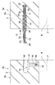
図12に示すように、複数のコンクリート製品80を連結する際は、数個〜数十個のコンクリート製品80が緊張棒84で連結される。かかる連結は剛接合であり、地震等により生じる変位を連結部で吸収することができないため、全てのコンクリート製品80を緊張棒で連結すると、コンクリート製品80が破損したり、コンクリート製品80間に隙間ができて水漏れが起こる恐れがある。
As shown in FIG. 12, when connecting a plurality of
したがって、変位が予想される場合、一部の連結部では、上記の剛接合による連結に代えて、帯状の弾性継ぎ手材90による連結が採用される。この弾性継ぎ手材90を用いた連結部では、止水性を確保しつつ変位をまとめて吸収することができる。
Therefore, when displacement is expected, in some of the connecting portions, instead of the connection by the rigid joint described above, the connection by the band-shaped elastic
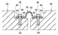
従来の弾性継ぎ手材90は、図13に示すように、略半円状の連結部92と、その連結部92の両側にそれぞれ連なる一対の押圧部94とからなる。そして、互いに隣接するコンクリート製品80は、それぞれの端部に予め埋め込まれたボルト84に弾性継ぎ手材90の押圧部94を固定することで、弾性継ぎ手材90によって連結される。そのように連結される両コンクリート製品80には、弾性継ぎ手材90が取り付けられるコーナー部に段状の切欠き86が予め形成されており、施工後において弾性継ぎ手材90が設備、水流および歩行の邪魔にならないようになっている。なお、弾性継ぎ手材90によってコンクリート製品80を連結する同様の構造は、例えば特許文献1に開示されている。
しかし、図13に示す弾性継ぎ手材90は、その長さによっては重量が非常に大きくなってしまい、例えば一辺の長さが2mである断面ロ字形のボックスカルバートの連結に用いる場合は、弾性継ぎ手材90とその固定に用いる部材96,98とを合わせた重量が、およそ100kgにも及ぶこととなる。施工現場において弾性継ぎ手材90を取り付ける作業者は、施工途中のボックスカルバートの中に入って、重量の大きな弾性継ぎ手材90等を取付け箇所まで持ち運ぶ必要があり、施工現場での運搬作業が大きな負担となっていた。
However, the elastic
また、従来は、弾性継ぎ手材90の押圧部94に設けられたボルト穴95に、コンクリート製品80に埋設された一つ一つのボルト84を通して固定しなければならず、取付け作業が煩雑となる欠点もあった。
Further, conventionally, the
さらに、弾性継ぎ手材90のボルト穴95は、コンクリート製品80のボルト84の位置に適合するように精度よく形成しておく必要があり、弾性継ぎ手材90の製作コストが高くなる問題もあった。他方、コンクリート製品80は、ボルト84を規定の間隔で精度よく埋め込んでおく必要があると共に、コンクリート製品80のコーナー部分に上記の切欠き86を形成しておく必要があるため、製作に手間がかかりコスト高を招いていた。
Furthermore, the
そこで、本発明は、コンクリート製品の連結部において、変位の吸収と止水性の確保とを実現しつつ、施工現場における運搬作業の負担軽減、施工の簡略化及びコストの低減化を図ることを目的とする。 Therefore, the present invention aims to reduce the burden of transportation work at the construction site, simplify the construction, and reduce the cost while realizing the absorption of displacement and securing the water stoppage in the connecting part of the concrete product. And
上記課題を解決するために、本発明の請求項1に係るコンクリート製品連結部の止水構造は、互いに隣接する一対のコンクリート製品間の連結部を止水するものにおいて、
一方のコンクリート製品の本体における連結側の端部に埋設された弾性継ぎ手材が、上記本体における連結側の端面より突出した突出部を備え、
上記突出部が、他方のコンクリート製品の本体における連結側の端面に設けられた凹溝に挿入され、上記他方のコンクリート製品が備える締結部材によって、上記凹溝の壁面に押し当てられた状態で締結されていることを特徴とする。
In order to solve the above problem, the water stop structure of the concrete product connecting portion according to
The elastic joint material embedded in the end portion on the connection side in the main body of one concrete product includes a protruding portion protruding from the end surface on the connection side in the main body,
The projecting portion is inserted into a concave groove provided on the end surface of the other concrete product on the connection side, and is fastened in a state of being pressed against the wall surface of the concave groove by a fastening member included in the other concrete product. It is characterized by being.
本発明の請求項2に係るコンクリート製品連結部の止水構造は、上記締結部材が、上記突出部を上記凹溝の壁面に押し当てる押し当て板と、その押し当て板を上記凹溝の壁面に近接させるボルト及びナットとからなり、上記押し当て板、上記ボルト及び上記ナットは、上記他方のコンクリート製品の本体に埋設されていることを特徴とする。
According to
本発明の請求項3に係るコンクリート製品連結部の止水構造は、上記突出部が、上記凹溝の壁面への押し当て面に止水用の突起が設けられていることを特徴とする。 The water stop structure of the concrete product connecting part according to claim 3 of the present invention is characterized in that the protrusion is provided with a water stop protrusion on the pressing surface against the wall surface of the concave groove.
本発明の請求項4に係るコンクリート製品連結部の止水構造は、上記突出部における上記凹溝の壁面への押し当て面側にシール材が取り付けられていることを特徴とする。
The water stop structure of the concrete product connecting portion according to
本発明の請求項5に係るコンクリート製品連結部の止水構造は、上記凹溝内における上記突出部の位置決めをするための位置決め用の突起が、上記突出部における上記凹溝の壁面への押し当て面とは反対側の面に設けられ、上記突出部が上記押し当て板によって上記凹溝の壁面に押し当てられた状態において、上記位置決め用の突起が、上記押し当て板よりも上記凹溝の深さ方向底部側に配置されていることを特徴とする。 According to a fifth aspect of the present invention, there is provided a water stop structure for a concrete product connecting portion, wherein a positioning projection for positioning the protruding portion in the concave groove is pressed against the wall surface of the concave groove in the protruding portion. The positioning projection is provided on the surface opposite to the contact surface, and in the state where the protrusion is pressed against the wall surface of the groove by the pressing plate, the positioning projection is more recessed than the pressing plate. It is arrange | positioned at the depth direction bottom part side.
本発明の請求項6に係るコンクリート製品連結部の止水方法は、互いに隣接する一対のコンクリート製品間の連結部を止水するものにおいて、
一方のコンクリート製品に、その本体における連結側の端面より突出するようにして弾性継ぎ手材を予め埋設すると共に、
他方のコンクリート製品の本体における連結側の端面に、上記弾性継ぎ手材を挿入するための凹溝を予め設け、且つ、他方のコンクリート製品の本体における連結側の端部に、上記弾性継ぎ手材を上記凹溝の壁面に押し当てた状態で締結するための締結部材を予め埋設し、
施工現場において、上記凹溝内に上記弾性継ぎ手材を挿入して上記締結部材により締結することで、上記一対のコンクリート製品を連結して止水することを特徴とする。
The water stopping method for the concrete product connecting portion according to claim 6 of the present invention is to stop the connecting portion between a pair of concrete products adjacent to each other.
In one concrete product, an elastic joint material is embedded in advance so as to protrude from the end surface on the connection side in the main body,
A concave groove for inserting the elastic joint material is provided in advance on an end face of the other concrete product main body on the connection side, and the elastic joint material is provided on an end of the other concrete product main body on the connection side. The fastening member for fastening in the state pressed against the wall surface of the concave groove is embedded in advance,
In the construction site, the elastic joint member is inserted into the groove and fastened by the fastening member, whereby the pair of concrete products are connected and water is stopped.
本発明の請求項7に係るコンクリート製品連結部の止水方法は、上記締結部材が、上記弾性継ぎ手材を上記凹溝の壁面に押し当てる押し当て板と、その押し当て板を上記凹溝の壁面に近接させるボルト及びナットとからなり、上記ボルト又は上記ナットの回転操作によって、上記押し当て板を上記凹溝の壁面に近接させて、上記弾性継ぎ手材の上記突出部を、上記凹溝の壁面と上記押し当て板との間に挟み込んで締結することを特徴とする。 According to a seventh aspect of the present invention, there is provided a water stopping method for a concrete product connecting portion, wherein the fastening member presses the elastic joint member against a wall surface of the concave groove, and the pressing plate is connected to the concave groove. A bolt and a nut that are brought close to the wall surface, and by rotating the bolt or the nut, the pressing plate is brought close to the wall surface of the concave groove, and the protruding portion of the elastic joint material is It is characterized by being clamped by being sandwiched between the wall surface and the pressing plate.
本発明の請求項8に係るコンクリート製品連結部の止水方法は、上記突出部における上記凹溝の壁面への押し当て面側にシール材を予め取り付け、上記弾性継ぎ手材を上記凹溝内で締結したときに、上記突出部と上記凹溝の壁面との間に上記シール材を介在させることを特徴とする。
According to
本発明の請求項9に係るコンクリート製品は、隣接する他のコンクリート製品と連結可能なものであって、
コンクリート製品の本体における少なくとも一方の連結側の端部に、上記他のコンクリート製品との連結に用いる弾性継ぎ手材が埋設され、
上記弾性継ぎ手材は、上記本体における上記連結側の端面より突出した突出部と、伸縮不能な状態で上記本体に固定された固定部と、上記突出部と上記固定部との間に設けられた伸縮可能な伸縮部とを備え、
上記伸縮部は、伸縮することによって上記本体の上記端面より出没可能となっていることを特徴とする。
The concrete product according to claim 9 of the present invention is connectable with another adjacent concrete product,
The elastic joint material used for connection with the other concrete product is embedded in the end of at least one connection side in the main body of the concrete product,
The elastic joint material is provided between the protruding portion that protrudes from the end surface on the coupling side of the main body, the fixing portion that is fixed to the main body in a non-stretchable state, and the protruding portion and the fixing portion. With a stretchable stretchable part,
The expansion / contraction part can extend and retract from the end surface of the main body by expanding and contracting.
本発明の請求項10に係るコンクリート製品は、上記伸縮部が蛇腹状であることを特徴とする。
The concrete product according to
本発明の請求項11に係るコンクリート製品は、上記固定部が、厚肉の抜け止め部を備えていることを特徴とする。 The concrete product according to an eleventh aspect of the present invention is characterized in that the fixed portion includes a thick retaining portion.
本発明の請求項12に係るコンクリート製品は、上記固定部と上記本体との間にシール材が介在していることを特徴とする。
The concrete product according to
本発明の請求項13に係るコンクリート製品は、隣接する他のコンクリート製品と連結可能なものであって、
コンクリート製品の本体における連結側の端面に、上記他のコンクリート製品に設けられた弾性継ぎ手材の一部を挿入するための凹溝が設けられると共に、上記本体の上記連結側の端部に、上記弾性継ぎ手材の一部を上記凹溝の壁面に押し当てた状態で締結するための締結部材が設けられていることを特徴とする。
The concrete product according to claim 13 of the present invention is connectable with another adjacent concrete product,
A concave groove for inserting a part of the elastic joint material provided in the other concrete product is provided on an end surface on the connection side in the main body of the concrete product, and the end on the connection side of the main body is provided with the above-mentioned A fastening member for fastening in a state where a part of the elastic joint material is pressed against the wall surface of the concave groove is provided.
本発明の請求項14に係るコンクリート製品は、上記締結部材が、上記弾性継ぎ手材の一部を上記凹溝の壁面に押し当てる押し当て板と、その押し当て板を上記凹溝の壁面に近接させるボルト及びナットとからなり、上記押し当て板、上記ボルト及び上記ナットは、上記本体に埋設されていることを特徴とする。
In the concrete product according to
本発明によれば、互いに隣接する一対のコンクリート製品を弾性継ぎ手材によって連結する場合に、予め弾性継ぎ手材が一方のコンクリート製品の本体に埋設されており、その弾性継ぎ手材を他方のコンクリート製品に固定するための凹溝及び締結部材が、予め他方のコンクリート製品に設けられているため、施工現場において弾性継ぎ手材及びその固定に用いる部材を連結箇所まで持ち運ぶ必要がなく、施工現場における運搬作業の負担を大幅に軽減することができる。 According to the present invention, when connecting a pair of adjacent concrete products with an elastic joint material, the elastic joint material is embedded in the body of one concrete product in advance, and the elastic joint material is used as the other concrete product. Since the concave groove and the fastening member for fixing are provided in the other concrete product in advance, it is not necessary to carry the elastic joint material and the member used for fixing to the connection place at the construction site, and the carrying work at the construction site is not necessary. The burden can be greatly reduced.
また、施工現場での連結作業は、弾性継ぎ手材を凹溝に挿入して、締結部材によって弾性継ぎ手材を凹溝壁面に押さえつけて締結するだけで済み、簡単な作業で確実に止水することができる。すなわち、多数のボルト穴にボルトを一つ一つ通して固定するといった従来の煩雑な作業が不要となり、施工を大幅に簡略化することができる。 In addition, the connection work at the construction site is as simple as inserting the elastic joint material into the groove and pressing the elastic joint material against the wall surface of the groove with the fastening member to fasten it. Can do. That is, the conventional troublesome work of fixing the bolts through a large number of bolt holes one by one is unnecessary, and the construction can be greatly simplified.
さらに、製作段階において、コンクリート製品に規定の間隔で精度よくボルトを埋設したり、弾性継ぎ手材に規定の間隔で精度よくボルト穴を形成したりする必要がないため、製作コストの低減化を図ることができる。 In addition, at the production stage, it is not necessary to embed bolts with high accuracy in the concrete product at specified intervals or to form bolt holes with high accuracy at the specified intervals in the elastic joint material, thereby reducing production costs. be able to.
加えて、弾性継ぎ手材は、コンクリート製品の相対的な変位に応じて伸縮可能であるため、コンクリート製品間に変位が生じた際、弾性継ぎ手材が伸縮することにより上記変位に追従することができ、コンクリート製品の破損や連結部の水漏れを確実に防止することができる。 In addition, since the elastic joint material can be expanded and contracted according to the relative displacement of the concrete product, when the displacement occurs between the concrete products, the elastic joint material can expand and contract to follow the displacement. In addition, it is possible to reliably prevent the breakage of the concrete product and the water leakage of the connecting portion.
以下、図面に基づいて、この発明の実施形態を詳細に説明する。図1は、コンクリート製品の一例である断面略ロ字形のボックスカルバート1を複数連結した状態を示す斜視図である。ただし、この発明は、隣接する他のコンクリート製品と連結可能なコンクリート製品であれば、断面略ロ字形のボックスカルバート1以外のコンクリート製品にも適用することができ、例えば、アーチ形のボックスカルバート、各種形状のフリューム、又はL型の擁壁等にも適用することができる。
Hereinafter, embodiments of the present invention will be described in detail with reference to the drawings. FIG. 1 is a perspective view showing a state in which a plurality of
ボックスカルバート1は、上下左右の壁部2から構成されている。また、各壁部2間のコーナー部4は、面取り加工が施されている。隣接するボックスカルバート1同士は、それらの端面を合わせた状態で、図示しない緊張棒又は弾性継ぎ手材10によって連結されている。一般的には、数個〜数十個の一群のボックスカルバート1が緊張棒によってまとめて連結され、それら一群のボックスカルバート1における端部のボックスカルバート1同士が弾性継ぎ手材10によって連結される。
The
図2は、互いに隣接する一対のボックスカルバート1a,1bの上側壁部2のうち、弾性継ぎ手材10によって連結される側の端部を示している。図2に示すように、一方のボックスカルバート1aは、その本体9aにおける連結側の端部に弾性継ぎ手材10が埋設されている。他方のボックスカルバート1bは、その本体9bにおける連結側の端面に、弾性継ぎ手材10を挿入するための凹溝40が設けられると共に、本体9bにおける連結側の端部に、弾性継ぎ手材10を凹溝40の壁面に押し当てた状態で締結するための締結部材41が埋設されている。
FIG. 2 shows an end of the pair of
弾性継ぎ手材10は、エンドレスの帯状に形成されており、図3に示すように、一方のボックスカルバート1aにおける連結側端部において全周に亘って設けられている。図2に示すように、弾性継ぎ手材10は、本体9aにおける連結側の端面より突出した突出部12と、伸縮不能な状態で本体9aに固定された固定部14と、突出部12と固定部14との間に設けられた伸縮可能な伸縮部16とを備えている。弾性継ぎ手材10の材質は、ゴム又は弾性エラストマーが適している。
The elastic
突出部12は、凹溝40壁面への押し当て面に例えば一対の止水用突起20を備えている。止水用突起20は、弾性継ぎ手材の長さ方向に沿ってレール状に設けられている。また、突出部12における凹溝40壁面への押し当て面側にはシール材22が取り付けてある。このシール材22は、止水用突起20に干渉しないようにして設けられている。シール材22としては、コンクリートとの接着性に優れたものが用いられ、非加硫ブチルゴム系シール材又は水膨張シール材が好適に用いられる。
The
非加硫ブチルゴム系シール材は、ブチル再生ゴムを用いた非加硫型粘着性塑性体であり、生モルタル(生コンクリート)の硬化反応が進行するのに従って、生モルタルと接着する性質を有している。この化学的結合については、セメント中に含まれる金属酸化物(例えばCaO、SiO2、Al2O3、Fe2O3)が、混合物中の水の存在下で金属水酸化物に変わり、この金属水酸化物が、再生ブチルゴム粒子の活性基(例えばカルボキシル基及びヒドロペルオキシド基)とイオン反応を起こすことによるものと考えられている。非加硫ブチルゴム系シール材の構成物質は、一般的に、再生ブチルゴム、充填材及び粘着材である。なお、非加硫ブチルゴム系シール材としては、「スパンシール」(登録商標)(早川ゴム株式会社製)が好適に用いられる。 Non-vulcanized butyl rubber sealant is a non-vulcanized adhesive plastic material using butyl recycled rubber and has the property of adhering to raw mortar as the curing reaction of raw mortar (green concrete) proceeds. ing. For this chemical bonding, the metal oxides contained in the cement (eg CaO, SiO 2 , Al 2 O 3 , Fe 2 O 3 ) are converted into metal hydroxides in the presence of water in the mixture, It is believed that the metal hydroxide is caused by an ionic reaction with the active groups (for example, carboxyl group and hydroperoxide group) of the regenerated butyl rubber particles. Generally, the constituent materials of the non-vulcanized butyl rubber-based sealing material are recycled butyl rubber, a filler, and an adhesive material. As the non-vulcanized butyl rubber sealant, “span seal” (registered trademark) (manufactured by Hayakawa Rubber Co., Ltd.) is preferably used.
水膨張シール材としては、吸水膨張する公知のシール材が用いられ、ゴムを主材とした弾性及び復元性に富むものが好適に用いられ、「ネオスパンシール」(登録商標)(早川ゴム株式会社製)が特に好適に用いられる。 As the water expansion seal material, a known seal material that absorbs and expands water is used, and a rubber-based material having high elasticity and resilience is preferably used. “Neospan seal” (registered trademark) (Hayakawa Rubber Co., Ltd.) (Made by company) is particularly preferably used.
また、突出部12の基端には厚肉部26が形成されている。他方、突出部12の先端部には、凹溝40壁面への押し当て面とは反対側の面に、凹溝40内における突出部12の位置決めをするための位置決め用の突起24が設けられている。したがって、凹溝40内に挿入した突出部12を締結する際に、突出部12の位置決め用突起24を、締結部材41の押し当て板42よりも凹溝40の深さ方向底部側に配置することを目安にして、凹溝40内における突出部12の位置決めを確実に行うことができる。
A
固定部14は、一方のボックスカルバート1aの本体9aに対して、完全に接着した状態で埋設されている。したがって、弾性継ぎ手材10に引き抜き方向の外力が加えられても、固定部14は、ボックスカルバート1aの本体9aから抜け外れないようになっている。また、固定部14は、その基端及び先端にそれぞれ厚肉の抜け止め部32を備えている。このように抜け止め部32を設けることで、ボックスカルバート1aの本体9aから固定部14が一層引き抜かれにくくなっている。
The fixing
また、固定部14の厚さ方向両側にはシール材30が積層されている。すなわち、一方のボックスカルバート1a本体9aと固定部14との間にシール材30が介在しており、本体9aと固定部14との間の止水性が高められている。このシール材30としては、上記のシール材22と同様、コンクリートとの接着性に優れたものが用いられ、非加硫ブチルゴム系シール材又は水膨張シール材が好適に用いられる。
In addition,
伸縮部16は、蛇腹状に形成されており、一方のボックスカルバート1aの本体9aに接着しないようにして埋設されている。具体的には、一方のボックスカルバート1aの本体9aに、その本体9aの連結側の端面側に開放する溝状のスロット36が形成されており、そのスロット36内に伸縮部16が収容されている。そして、伸縮部16は、伸縮することによって本体9aの上記端面より出没可能となっている。
The expansion /
他方のボックスカルバート1bにおける凹溝40は、弾性継ぎ手材10の突出部12を収容可能な所定幅及び所定深さを有するように形成されている。また、凹溝40は、図4に示すように、他方のボックスカルバート1bにおける連結側の端部において全周に亘って設けられている。
The
なお、図11に示すその他の実施形態のように、凹溝40の周囲にゴム板70又は鋼製枠を予め埋設しておくようにしても良く、その場合は、コンクリートのジャンカの発生等による止水性の悪化を防ぐことができる。
In addition, as in other embodiments shown in FIG. 11, a
締結部材41は、図2に示すように、弾性継ぎ手材10を凹溝40の壁面に押し当てる押し当て板42と、その押し当て板42を凹溝40の壁面に近接させるボルト44及びナット46とからなる。
As shown in FIG. 2, the
押し当て板42は、帯状に形成されており、図4に示すように、他方のボックスカルバート1bの連結側端部において全周に亘って設けられている。また、押し当て板42は、凹溝40における弾性継ぎ手材10の突出部12が押し当てられる壁面の内周側に設けられている。また、押し当て板42は、長さ方向において適当な長さに分割された状態で設けられている。押し当て板42としては、小口分割が可能で衝撃に強い金属板が好適に用いられ、溶融亜鉛メッキ鋼板が特に好適に用いられる。
The
ボルト44及びナット46は、図2に示すように、ボルト44の一端側のみが露出するように螺合した状態で、且つ、ナット46におけるボルト44の露出側とは反対側の端面が押し当て板42に当接した状態で、他方のボックスカルバート1bの本体9bに埋設されている。ボルト44の露出部分は、ボックスカルバート1bの本体9b内壁面に形成された凹部48に、本体9bのコンクリートが付着しないようにして収容されている。したがって、ボックスカルバート1bの壁部2に囲まれた内部空間8において、ボルト44の回転操作が可能となっている。
As shown in FIG. 2, the
ボルト44及びナット46は、図4に示すようにリング状に配置された押し当て板42の内周側において、周方向に適当な間隔を空けて設けられている。ボックスカルバート1bの外形を一辺の長さが1800mmである正方形状とした場合、ボルト44及びナット46は、例えば200mmのピッチで設けられ、面取り加工が施されたコーナー部4にも必要個数のボルト44及びナット46が設けられる。ボルト44及びナット46の材質は、防錆の観点からステンレスが好ましく、特にSUS304が好ましい。
The
弾性継ぎ手材10によってボックスカルバート1a,1bを連結する際は、図5に示すように、先ず、一方のボックスカルバート1aにおける弾性継ぎ手材10の突出部12を、他方のボックスカルバート1bの凹溝40に挿入する。続いて、ボルト44の回転操作によって、ナット46に対してボルト44を螺進させることで、ボルト44の先端で押し当て板42を押して、押し当て板42を凹溝40の壁面に近接させ、図6に示すように、弾性継ぎ手材10の突出部12を、凹溝40の壁面と押し当て板42との間に挟み込んで締結する。なお、この実施形態では、ボルト44の回転操作により押し当て板42を凹溝40の壁面に近接させるようにしているが、ボルト及びナットの構造は特に限定されるものではなく、ナットの回転操作により押し当て板42を凹溝40の壁面に近接させるようにしても良い。
When the
このとき、突出部12の位置決め用突起24が、押し当て板42よりも凹溝40の深さ方向底部側に配置されるようにする。これにより、位置決め用突起24が抜け止め機能を発揮することができ、突出部12が凹溝40内に一層確実に固定される。
At this time, the
このように、一方のボックスカルバート1aに弾性継ぎ手材10を予め埋設すると共に、他方のボックスカルバート1bに凹溝40及び締結部材41を予め設けておくことで、施工現場においては、凹溝40内に弾性継ぎ手材10を挿入して締結部材41により締結するだけで、一対のボックスカルバート1a,1bを簡単に連結することができ、従来に比べて施工を大幅に簡略化することができる。
As described above, the elastic
また、上述のように一対のボックスカルバート1a,1bを連結したとき、弾性継ぎ手材10の突出部12は、締結部材41によって強固に締結されているため、一対のボックスカルバート1a,1b間の連結部は、弾性継ぎ手材10によって確実に止水された状態となっている。しかも、弾性継ぎ手材10の突出部12に設けられた止水用突起20が、高い圧力で凹溝40の壁面に密着すると共に、突出部12と凹溝40の壁面との間に、コンクリートに対して高い接着力を有するシール材22が介在することとなるため、連結部の止水性は一層高められている。
In addition, when the pair of
図7は、ボックスカルバート1a,1bの軸方向の変位が生じることによって、弾性継ぎ手材10によって連結された一対のボックスカルバート1a,1bの本体9a,9b間の間隔が拡がった状態を示している。弾性継ぎ手材10は、伸縮部16が伸縮することで、ボックスカルバート1a,1bの相対的な変位に応じて伸縮可能となっている。図7に示すような変位が生じた場合は、弾性継ぎ手材10の伸縮部16が、変位に応じて伸長するようになっているため、弾性継ぎ手材10によって変位を吸収することができ、ボックスカルバート1a,1bの破損を防ぐことができる。また、このとき、弾性継ぎ手材10の突出部12は、他方のボックスカルバート1bに強固に固定されているため、ボックスカルバート1a,1b間の止水性は維持された状態となっており、連結部における水漏れの発生を防ぐことができる。
FIG. 7 shows a state in which the distance between the
図8は、ボックスカルバート1a,1bの横断面方向の変位が生じることによって、弾性継ぎ手材10によって連結された一対のボックスカルバート1a,1bの本体9a,9b間に、高さ方向のずれが生じた状態を示している。この場合も、弾性継ぎ手材10の伸縮部16は、変位に応じて伸長するようになっているため、弾性継ぎ手材10によって変位を吸収することができる。したがって、図7に示す場合と同様、ボックスカルバート1a,1bの破損を防ぐことができると共に、連結部における水漏れの発生を防ぐことができる。
FIG. 8 shows that the displacement in the cross-sectional direction of the
弾性継ぎ手材10の製造には、例えばプレス加硫装置を用いる。この場合、プレス加硫装置に、未加硫のゴム材料又はエラストマー材料を仕込んでプレスすることで、加硫と成型を同時に行う。続いて、それによって得られた成型品を規定の長さにカットし、カットした成型品の端部間に上記と同一の未加硫材料を挟み込んだ状態で再度プレス加硫を行うことで、カットした成型品の端部同士をつなぎ合わせて、エンドレスのリング状に形成された弾性継ぎ手材10を得ることができる。
For example, a press vulcanizer is used to manufacture the elastic
上記一方のボックスカルバート1aを製造する際は、型枠にコンクリートを打設する前に、型枠内に弾性継ぎ手材10を予め設置しておく。弾性継ぎ手材10を型枠に設置する際は、型枠内に配された鉄筋等に弾性継ぎ手材10を緊結して設置する。
When manufacturing the one
また、型枠にコンクリートを打設する前に、弾性継ぎ手材10の固定部14の両面、及び突出部12における凹溝40壁面への押し当て面には、それぞれシール材22,30を貼り付けておく。さらに、伸縮部16がコンクリートに接着しないように、図9に示すように、伸縮部16の両面にテープ54を貼り付けておく。これにより、コンクリートの打設後に、ボックスカルバート1aの本体9a端面に溝状のスロット36が形成され、伸縮部16は、コンクリートに接着することなくスロット36内に収容されることとなる。またさらに、突出部12がコンクリートに接着するのを防ぐため、突出部12を型枠材50の溝部52に収めておく。
Further, before placing concrete on the mold,
型枠内に弾性継ぎ手材10を設置し、コンクリートを打設して硬化させた後、脱型することで、本体9aに弾性継ぎ手材10が埋設されてなるボックスカルバート1aを得ることができる。このように、弾性継ぎ手材10を本体9aに埋設して一体化しておくことで、施工を簡略化できると共に、弾性継ぎ手材10が施工現場において脱落しないようになっている。
The box
上記他方のボックスカルバート1bを製造する際は、図10に示すように、凹溝40を成型するためのレール部62を備えた型枠材60を用いることで、ボックスカルバート1bの本体9bにおける連結側の端面に凹溝40が形成される。また、型枠内に締結部材41を設置しておくことで、ボックスカルバート1bの本体9bに締結部材41が埋設される。このように、締結部材41を本体9bに埋設して一体化しておくことで、施工を簡略化できると共に、施工現場において締結部材41が脱落しないようになっている。
When the
型枠に締結部材41を設置する際は、締結部材41の押し当て板42、ボルト44及びナット46を、それぞれ型枠内に配された鉄筋等に緊結しておく。このとき、押し当て板42は、型枠材60のレール部62に当接した状態で固定する。これにより、押し当て板42が、凹溝40における弾性継ぎ手材10の突出部12が押し当てられる壁面に対向した状態で、ボックスカルバート1bの本体9bに埋設される。
When the
ボルト44及びナット46は、ボルト44の一端側のみが露出するように螺合した状態で、ナット46におけるボルト44の露出側とは反対側の端面を押し当て板42に当接させた状態で固定する。また、ボルト44がコンクリートに接着しないように、ボルト44の露出部分を例えばゴム製のキャップ64で覆っておく。これにより、コンクリートを打設して硬化させた後にキャップ64を取り外すことで、図2に示すように、ボックスカルバート1bの本体9b内壁面に凹部48が形成され、ボックスカルバート1bの内部空間8から回転操作が可能なように、ボルト44が凹部48に収容された状態となる。
The
1a 一方のボックスカルバート(コンクリート製品)
1b 他方のボックスカルバート(コンクリート製品)
9a 一方のボックスカルバート(コンクリート製品)の本体
9b 他方のボックスカルバート(コンクリート製品)の本体
10 弾性継ぎ手材
12 突出部
14 固定部
16 伸縮部
20 止水用の突起
22,30 シール材
24 位置決め用の突起
32 抜け止め部
40 凹溝
41 締結部材
42 押し当て板
44 ボルト
46 ナット
1a One box culvert (concrete product)
1b The other box culvert (concrete product)
9a Main body of one box culvert (concrete product) 9b Main body of the other box culvert (concrete product) 10 Elastic
Claims (14)
一方のコンクリート製品の本体における連結側の端部に埋設された弾性継ぎ手材が、上記本体における連結側の端面より突出した突出部を備え、
上記突出部が、他方のコンクリート製品の本体における連結側の端面に設けられた凹溝に挿入され、上記他方のコンクリート製品が備える締結部材によって、上記凹溝の壁面に押し当てられた状態で締結されていることを特徴とするコンクリート製品連結部の止水構造。 In the water stop structure of the concrete product connection part that stops the connection part between a pair of concrete products adjacent to each other,
The elastic joint material embedded in the end portion on the connection side in the main body of one concrete product includes a protruding portion protruding from the end surface on the connection side in the main body,
The projecting portion is inserted into a concave groove provided on the end surface of the other concrete product on the connection side, and is fastened in a state of being pressed against the wall surface of the concave groove by a fastening member included in the other concrete product. A water stop structure for a concrete product connecting part.
一方のコンクリート製品に、その本体における連結側の端面より突出するようにして弾性継ぎ手材を予め埋設すると共に、
他方のコンクリート製品の本体における連結側の端面に、上記弾性継ぎ手材を挿入するための凹溝を予め設け、且つ、他方のコンクリート製品の本体における連結側の端部に、上記弾性継ぎ手材を上記凹溝の壁面に押し当てた状態で締結するための締結部材を予め埋設し、
施工現場において、上記凹溝内に上記弾性継ぎ手材を挿入して上記締結部材により締結することで、上記一対のコンクリート製品を連結して止水することを特徴とするコンクリート製品連結部の止水方法。 In the water stopping method of the concrete product connecting part for stopping the connecting part between a pair of concrete products adjacent to each other,
In one concrete product, an elastic joint material is embedded in advance so as to protrude from the end surface on the connection side in the main body,
A concave groove for inserting the elastic joint material is provided in advance on an end face of the other concrete product main body on the connection side, and the elastic joint material is provided on an end of the other concrete product main body on the connection side. The fastening member for fastening in the state pressed against the wall surface of the concave groove is embedded in advance,
The water stop of a concrete product connecting portion characterized in that, at a construction site, the elastic joint member is inserted into the concave groove and fastened by the fastening member to connect and stop the pair of concrete products. Method.
コンクリート製品の本体における少なくとも一方の連結側の端部に、上記他のコンクリート製品との連結に用いる弾性継ぎ手材が埋設され、
上記弾性継ぎ手材は、上記本体における上記連結側の端面より突出した突出部と、伸縮不能な状態で上記本体に固定された固定部と、上記突出部と上記固定部との間に設けられた伸縮可能な伸縮部とを備え、
上記伸縮部は、伸縮することによって上記本体の上記端面より出没可能となっていることを特徴とするコンクリート製品。 A concrete product connectable with other adjacent concrete products,
The elastic joint material used for connection with the other concrete product is embedded in the end of at least one connection side in the main body of the concrete product,
The elastic joint material is provided between the protruding portion that protrudes from the end surface on the coupling side of the main body, the fixing portion that is fixed to the main body in a non-stretchable state, and the protruding portion and the fixing portion. With a stretchable stretchable part,
The concrete product according to claim 1, wherein the stretchable portion can extend and retract from the end face of the main body by expanding and contracting.
コンクリート製品の本体における少なくとも一方の連結側の端面に、上記他のコンクリート製品に設けられた弾性継ぎ手材の一部を挿入するための凹溝が設けられると共に、上記本体の上記連結側の端部に、上記弾性継ぎ手材の一部を上記凹溝の壁面に押し当てた状態で締結するための締結部材が設けられていることを特徴とするコンクリート製品。 A concrete product connectable with other adjacent concrete products,
A concave groove for inserting a part of the elastic joint material provided in the other concrete product is provided on an end surface of at least one connection side in the main body of the concrete product, and an end portion on the connection side of the main body. And a fastening member for fastening in a state where a part of the elastic joint material is pressed against the wall surface of the groove.
The fastening member includes a pressing plate that presses a part of the elastic joint material against the wall surface of the concave groove, and a bolt and a nut that brings the pressing plate close to the wall surface of the concave groove, and the pressing plate The concrete product according to claim 13, wherein the bolt and the nut are embedded in the main body.
Priority Applications (1)
| Application Number | Priority Date | Filing Date | Title |
|---|---|---|---|
| JP2006017824A JP2007198007A (en) | 2006-01-26 | 2006-01-26 | Water cutoff structure for concrete product connection section, water cutoff method for concrete product connection section, and concrete product |
Applications Claiming Priority (1)
| Application Number | Priority Date | Filing Date | Title |
|---|---|---|---|
| JP2006017824A JP2007198007A (en) | 2006-01-26 | 2006-01-26 | Water cutoff structure for concrete product connection section, water cutoff method for concrete product connection section, and concrete product |
Publications (1)
| Publication Number | Publication Date |
|---|---|
| JP2007198007A true JP2007198007A (en) | 2007-08-09 |
Family
ID=38452873
Family Applications (1)
| Application Number | Title | Priority Date | Filing Date |
|---|---|---|---|
| JP2006017824A Pending JP2007198007A (en) | 2006-01-26 | 2006-01-26 | Water cutoff structure for concrete product connection section, water cutoff method for concrete product connection section, and concrete product |
Country Status (1)
| Country | Link |
|---|---|
| JP (1) | JP2007198007A (en) |
Cited By (5)
| Publication number | Priority date | Publication date | Assignee | Title |
|---|---|---|---|---|
| JP2009068217A (en) * | 2007-09-12 | 2009-04-02 | Seibu Polymer Corp | Joint structure of concrete structure and method of constructing the same |
| WO2013078732A1 (en) * | 2011-11-29 | 2013-06-06 | Jiang Yun | Prefabricated building block for assembling well wall |
| JP5632511B1 (en) * | 2013-06-20 | 2014-11-26 | 一剛 小島 | Tsunami danger area shelter unit |
| WO2015160059A1 (en) * | 2014-04-15 | 2015-10-22 | 주식회사 케이씨산업 | Corrugated hollow closed water stop, concrete culvert using same, and construction method therefor |
| KR102517949B1 (en) * | 2022-05-03 | 2023-04-03 | 김성우 | Buried box structure for staggered lapping and method for construction of slurry wall using the same |
Citations (6)
| Publication number | Priority date | Publication date | Assignee | Title |
|---|---|---|---|---|
| JPS6153932A (en) * | 1984-08-20 | 1986-03-18 | 高見 恭司 | Connection of concrete product |
| JPH0726613A (en) * | 1993-06-25 | 1995-01-27 | Hayakawa Rubber Co Ltd | Joint structure of concrete construction |
| JPH10131319A (en) * | 1996-11-01 | 1998-05-19 | Yamatsukusu:Kk | Cut-off joint member of concrete joining object |
| JPH11166244A (en) * | 1997-12-03 | 1999-06-22 | Hayakawa Rubber Co Ltd | Joint construction, expansion fixed band and positioning device of pipe |
| JP2001081853A (en) * | 1999-09-13 | 2001-03-27 | Hokukon Co Ltd | Flexible aseismatic joint structure of concrete member |
| JP2004162339A (en) * | 2002-11-12 | 2004-06-10 | Hayakawa Rubber Co Ltd | Cut off joint for manhole, pipe joint, manhole structure, and work execution method for the structure |
-
2006
- 2006-01-26 JP JP2006017824A patent/JP2007198007A/en active Pending
Patent Citations (6)
| Publication number | Priority date | Publication date | Assignee | Title |
|---|---|---|---|---|
| JPS6153932A (en) * | 1984-08-20 | 1986-03-18 | 高見 恭司 | Connection of concrete product |
| JPH0726613A (en) * | 1993-06-25 | 1995-01-27 | Hayakawa Rubber Co Ltd | Joint structure of concrete construction |
| JPH10131319A (en) * | 1996-11-01 | 1998-05-19 | Yamatsukusu:Kk | Cut-off joint member of concrete joining object |
| JPH11166244A (en) * | 1997-12-03 | 1999-06-22 | Hayakawa Rubber Co Ltd | Joint construction, expansion fixed band and positioning device of pipe |
| JP2001081853A (en) * | 1999-09-13 | 2001-03-27 | Hokukon Co Ltd | Flexible aseismatic joint structure of concrete member |
| JP2004162339A (en) * | 2002-11-12 | 2004-06-10 | Hayakawa Rubber Co Ltd | Cut off joint for manhole, pipe joint, manhole structure, and work execution method for the structure |
Cited By (7)
| Publication number | Priority date | Publication date | Assignee | Title |
|---|---|---|---|---|
| JP2009068217A (en) * | 2007-09-12 | 2009-04-02 | Seibu Polymer Corp | Joint structure of concrete structure and method of constructing the same |
| WO2013078732A1 (en) * | 2011-11-29 | 2013-06-06 | Jiang Yun | Prefabricated building block for assembling well wall |
| JP5632511B1 (en) * | 2013-06-20 | 2014-11-26 | 一剛 小島 | Tsunami danger area shelter unit |
| WO2015160059A1 (en) * | 2014-04-15 | 2015-10-22 | 주식회사 케이씨산업 | Corrugated hollow closed water stop, concrete culvert using same, and construction method therefor |
| CN105189875A (en) * | 2014-04-15 | 2015-12-23 | Kc工业株式会社 | Corrugated hollow closed water stop, concrete culvert using same, and construction method therefor |
| CN105189875B (en) * | 2014-04-15 | 2017-05-10 | Kc工业株式会社 | Corrugated hollow closed water stop, concrete culvert using same, and construction method therefor |
| KR102517949B1 (en) * | 2022-05-03 | 2023-04-03 | 김성우 | Buried box structure for staggered lapping and method for construction of slurry wall using the same |
Similar Documents
| Publication | Publication Date | Title |
|---|---|---|
| WO2014192442A1 (en) | Flange joining structure and seal body used therein | |
| JP2007198007A (en) | Water cutoff structure for concrete product connection section, water cutoff method for concrete product connection section, and concrete product | |
| US20160238183A1 (en) | Spacer for positioning a rehabilitating pipe | |
| US7028972B2 (en) | Gasket and mandrel assembly for pipe joints | |
| JP2009138334A (en) | Expansion joint for road bridge | |
| KR100805842B1 (en) | A joint device and construction method of concrete structure | |
| KR101202372B1 (en) | Water-tighting coupler for wave type steel plate | |
| JP2008038426A (en) | Flexible water stop joint and its construction method | |
| KR101311589B1 (en) | Apparatus for connecting shaped tubes of manhole pipeline | |
| JP3127038U (en) | Box culvert | |
| KR20150039970A (en) | Pre-cast panel bond structure of bridge extension slab | |
| JP4567564B2 (en) | Underwater waterproof flexible joint | |
| JP5343262B2 (en) | Repair structure and repair method for flexible waterproof joint | |
| KR101088707B1 (en) | A jointing device for corrugated stell pipes | |
| JP5801677B2 (en) | Flexible joint for manhole and installation method thereof | |
| JP2006161441A (en) | Telescopic post-construction type flexible joint device of concrete structure | |
| JP2721472B2 (en) | Concrete structure joint structure | |
| JP3908416B2 (en) | Underwater joint for high water pressure | |
| JP5901480B2 (en) | Damaged part sealing band in the tube | |
| JP2009013673A (en) | Water channel block, water channel structure, and water channel block manufacturing method | |
| JP2005113477A (en) | Tunnel segment and forming method | |
| JP2514127Y2 (en) | Concrete block with waterproof joint | |
| JP5727863B2 (en) | Water stop member for manhole repair and manhole repair method | |
| JP3863344B2 (en) | Flexible joint for secondary lining pipe of shield tunnel | |
| JP3597506B2 (en) | Connection structure of open block |
Legal Events
| Date | Code | Title | Description |
|---|---|---|---|
| A621 | Written request for application examination |
Free format text: JAPANESE INTERMEDIATE CODE: A621 Effective date: 20080717 |
|
| A977 | Report on retrieval |
Free format text: JAPANESE INTERMEDIATE CODE: A971007 Effective date: 20100817 |
|
| A131 | Notification of reasons for refusal |
Free format text: JAPANESE INTERMEDIATE CODE: A131 Effective date: 20100824 |
|
| A02 | Decision of refusal |
Free format text: JAPANESE INTERMEDIATE CODE: A02 Effective date: 20101221 |