JP2007192801A - Measuring method of elasticity using sound wave - Google Patents
Measuring method of elasticity using sound wave Download PDFInfo
- Publication number
- JP2007192801A JP2007192801A JP2006286898A JP2006286898A JP2007192801A JP 2007192801 A JP2007192801 A JP 2007192801A JP 2006286898 A JP2006286898 A JP 2006286898A JP 2006286898 A JP2006286898 A JP 2006286898A JP 2007192801 A JP2007192801 A JP 2007192801A
- Authority
- JP
- Japan
- Prior art keywords
- sound
- measurement object
- elasticity
- measurement
- microphone
- Prior art date
- Legal status (The legal status is an assumption and is not a legal conclusion. Google has not performed a legal analysis and makes no representation as to the accuracy of the status listed.)
- Pending
Links
Images


Classifications
-
- G—PHYSICS
- G01—MEASURING; TESTING
- G01N—INVESTIGATING OR ANALYSING MATERIALS BY DETERMINING THEIR CHEMICAL OR PHYSICAL PROPERTIES
- G01N2291/00—Indexing codes associated with group G01N29/00
- G01N2291/02—Indexing codes associated with the analysed material
- G01N2291/028—Material parameters
- G01N2291/02827—Elastic parameters, strength or force
Abstract
Description
本発明は、野菜の湿度、温度など保存条件による鮮度測定、遮音建材の湿度、温度、日射など環境条件に対する特性変化測定、可塑材料の熱特性の測定、人の皮膚の老化診断など、広く弾性特性を持つ素材の特性変化測定、診断に適用する音波を用いた弾性特性の測定方法に関する。 The present invention has a wide range of elasticity, such as freshness measurement according to storage conditions such as humidity and temperature of vegetables, measurement of characteristic changes to environmental conditions such as humidity, temperature and solar radiation of sound insulation building materials, measurement of thermal characteristics of plastic materials, aging diagnosis of human skin, etc. The present invention relates to a method for measuring a change in characteristics of a material having characteristics and a method for measuring an elastic characteristic using sound waves applied to diagnosis.
従来、野菜の鮮度診断、人の皮膚の老化診断、可塑材料の熱特性や遮音建材の湿度、温度、日射などの環境条件に対する特性変化は視覚や応力測定で定性的に評価され、非接触で変化の諸要因に対する因果を明確にする詳細な計測方法は社会ニーズに十分応えることができていない。その中で、200Hz付近の振動を発生させる振動子を野菜に接触させ、それを透過した振動の波形変化から野菜の鮮度を評価しようとする試みや、空気の衝撃波を人の皮膚に当てて皮膚にできたくぼみのレーザー光反射強度の変化から人の皮膚の老化を診断するなどの新規診断法への黎明が見られているが、これを弾性体の非線形弾性特性にもとづくカオティックな応答として信号処理し定性、定量評価するまでには至っていないし、ましてそれを簡便な非接触計測方法として確立されていなかった。
たとえば、弾性の非線形特性をもとに野菜を透過した振動の波形変化から野菜の鮮度を評価しようとする試みでは、視覚や応力変化だけでは、野菜の経時変化は計測できても、その鮮度としての温度、湿度、日射など保存条件の諸要因との関係の評価には至っていないし、皮膚の老化評価についても空気の衝撃波により形成されたくぼみの復帰変化をレーザー光の反射測定で計測できているが、経時変化や変化率の提示にとどまっている問題点がある。 For example, in an attempt to evaluate the freshness of a vegetable from the change in the waveform of vibration that has passed through the vegetable based on the nonlinear characteristics of elasticity, even if the change over time of the vegetable can be measured by visual and stress changes alone, Evaluation of the relationship between various factors of storage conditions such as temperature, humidity, and solar radiation has not been achieved, and for skin aging evaluation, the return change of the depression formed by the shock wave of air can be measured by reflection measurement of laser light. However, there is a problem that it is only presenting changes over time and rate of change.
上記課題の解決の方法として、本発明では非線形特性をもつ弾性体に外部から振動を与えると、弾性体からの応答はカオティックになり、それは弾性体の非線形性の微小な変化で、応答信号波形が大きく変化することで、X−Y直交座標表示装置でこの信号をX軸上で、これに位相遅れを与えた信号をY軸上で変化させ重ね合わすと、同じ軌道を通らないループ状の2次元図形、いわゆるアトラクタと呼ばれる、ある座標を中心とする非再帰軌道図形が大きく変化することから、弾性体の非線形弾性特性に微小変化を与える外的環境条件、たとえば建材や野菜に対する湿度、温度、日照の影響、人の皮膚の弾性特性に微小変化を与える疲労、ストレス、食物などの影響を視覚で明確に判定できることで、これを反射音響の測定から非接触で計測しようとするものである。 As a method of solving the above problem, in the present invention, when an elastic body having nonlinear characteristics is subjected to vibration from the outside, the response from the elastic body becomes chaotic, which is a minute change in the nonlinearity of the elastic body, and the response signal waveform. When this signal is changed on the X-axis and the signal to which the phase lag is given is changed on the Y-axis and superimposed on the XY rectangular coordinate display device, the loop shape does not pass through the same trajectory. A non-recursive orbit figure centered on a certain coordinate called a so-called attractor changes greatly, so external environment conditions that give minute changes to the nonlinear elastic properties of elastic bodies, such as humidity and temperature for building materials and vegetables The effect of sunlight, fatigue that gives minute changes to human skin elasticity, stress, food, and other effects can be clearly determined visually. It is intended to.
本発明は弾力特性を計測される測定対象物と、該測定対象物に離間して配置され可聴周波数の音波を出力するスピーカーと、前記測定対象物からの反射音を収集するマイクロフォンとを備え、前記マイクロフォンからの反射音をAD変換して、カオティックな非周期的変化の図形を表示装置に表示して非接触測定により測定対象物の弾性特性を測定する特徴がある。 The present invention includes a measurement object whose elasticity characteristics are measured, a speaker that is disposed apart from the measurement object and outputs sound waves having an audible frequency, and a microphone that collects reflected sound from the measurement object. The reflected sound from the microphone is AD-converted, a chaotic non-periodic change figure is displayed on a display device, and the elastic characteristic of the measurement object is measured by non-contact measurement.
また、本発明では前記可聴周波数の音波は交互にパルス状に出力されて前記測定対象物に加え、その反射音を切り出して結合した受音波形を用いて前記表示装置にカオティックな非周期的変化の図形を表示することを特徴とする。 Further, in the present invention, the sound wave of the audible frequency is alternately output in a pulse shape and added to the measurement object, and the reflected sound is cut out and coupled to the display device using a chaotic aperiodic change. The figure is displayed.
更に、本発明では前記マイクロフォンは前記スピーカーの前面に同軸状に配置して前記測定対象物からの反射音を切り出して収集することを特徴とする。 Furthermore, the present invention is characterized in that the microphone is coaxially arranged on the front surface of the speaker, and the reflected sound from the measurement object is cut out and collected.
更に、本発明では前記表示装置としてX―Y直交座標表示装置を用い、前記受音波形とその位相遅れ処理後の信号をそれぞれの座標に加えて描くアトラクタの変化で前記測定対象物の弾性特性を測定することを特徴とする。 Further, in the present invention, an XY orthogonal coordinate display device is used as the display device, and the elastic characteristics of the measurement object are determined by a change in the attractor drawn by adding the received wave shape and the signal after the phase delay processing to the respective coordinates. Is measured.
更に、本発明では前記位相遅れ処理は3サンプル期間とすることを特徴とする。 Furthermore, the present invention is characterized in that the phase delay processing is performed for three sample periods.
本発明によれば、これまで定性的で経時的にしか表示できなかった、たとえば野菜の湿度、温度など保存条件による鮮度測定、遮音建材の湿度、温度、日射など環境条件に対する特性変化測定、可塑材料の熱特性の測定、人の皮膚の老化診断などを非接触で従来以上に精密に計測評価できる。 According to the present invention, qualitative and can only be displayed over time, for example, freshness measurement under storage conditions such as humidity and temperature of vegetables, measurement of characteristic changes with respect to environmental conditions such as humidity, temperature and solar radiation of sound insulation materials, plasticity Non-contact measurement and evaluation of thermal characteristics of materials and aging diagnosis of human skin can be performed more precisely than ever.
また、本発明では音波を利用することで非接触、食品や生体に無害で、しかも装置がスピーカーとマイクロフォン、に加え、アナログデジタル変換器とパソコン、近年ではアナログデジタル変換器はパソコンに組み込んでコンパクトに構成できることから、装置が簡素で携帯が容易であることから、野菜の収穫評価する現場や建設現場にも可搬できる高い適用性がある。 In the present invention, sound waves are used for non-contact, harmless to food and living bodies, and in addition to a speaker and a microphone, the device is an analog-digital converter and a personal computer. In recent years, an analog-digital converter is built into a personal computer and is compact. Therefore, since the apparatus is simple and easy to carry, there is a high applicability that it can be transported to the site where the harvest of vegetables is evaluated and the construction site.
更に、本発明ではマイクロフォンからの出力波形から作った反射波期間取り出し結合波形を用いて、埋め込み次元は2、遅れ時間τ=3サンプルを採用したアトラクタを表示できるので、弾性体の特性をX―Y直交座標表示装置にアトラクタの図形を分かりやすく表示できる。 Furthermore, in the present invention, an attractor using a reflected wave period extraction combined waveform made from an output waveform from a microphone and using an embedded dimension of 2 and a delay time τ = 3 samples can be displayed. The attractor figure can be displayed in an easy-to-understand manner on the Y rectangular coordinate display device.
更に、本発明ではアトラクタの作図を遅れ時間τ=3サンプル期間にすることで、アトラクタに最も変化が表れたものが表示できる。 Furthermore, in the present invention, by drawing the attractor to the delay time τ = 3 sample periods, it is possible to display the attractor with the most change.
以下、本発明の実施の形態における、音波の非線形応答による弾性体の特性計測法ならびにそれを具現化した簡便計測装置を、図面にもとづき説明する。 Hereinafter, a method for measuring characteristics of an elastic body based on a nonlinear response of sound waves and a simple measuring apparatus embodying the same will be described with reference to the drawings.
本実施の形態においては、図1に示す石膏ボードや合板などの測定対象物1を対象とし、音波の送受から最適とした2msの方形波信号を20ms毎に発振器6により発生させ、それを遮音ボックス4内の、スピーカー2で音波にして測定対象物1に投射し、弾性体である測定対象物1の表面に振動を起させ、そのときの測定対象物1の表面からの反射音を遮音隔壁5でスピーカー2からの発生音を遮断するように配置されたマイクロフォン3で受音し、信号をアナログデジタル変換器9でデジタル変換後、パソコン10で、アトラクタを描かせ、測定対象物1の諸要因による変化を図形より評価するように構成する。
In this embodiment, the
本発明に関わるアトラクタの表示は、測定対象物からの図2に示す反射音8を、マイクロフォン3で受音し、その信号をアナログデジタル変換器9でデジタル信号12に変換後、それをそのまま信号表示用直交座標画面の横軸14、すなわちX軸に加えるとともに、受音信号を図2の位相遅延器11で受音信号よりτ秒送らせ(13)、それを図2の信号表示用直交座標画面の縦軸15、すなわちY軸に加え、信号の軌道図形を図2のアトラクタ16のように描かせ、計測対象の弾性特性に影響を与える諸要因の影響を、アトラクタを表示する信号変化の軌道図形として評価できるように構成する。
The attractor according to the present invention displays the
次に、具体的な実験方法および条件を図3を参照して説明する。実験は無響室ではなく一般の教室で行った。縦が600cm、横が700cm、高さが280cmの教室を用いて、スピーカー3、マイクロフォン2および測定対象物1を床からの高さ104cmに並べ、スピーカー3の前面に同軸方向にマイクロフォン2を配置し、両者の先端部を44cm離間させ、マイクロフォン2の先端部と測定対象物1とを60cm離間して配置している。教室の壁面とスピーカー3、マイクロフォン2および測定対象物1は十分に離間させて、スピーカー3からの音波が測定対象物1からの反射音がマイクロフォン2に到達するまでに教室の壁面から反射してマイクロフォン2に収集されないように配慮している。図3は教室を天井側から見た上面図である。なお、図3の配置は図1に示す配置とは異なっているが、種々の配置が考えられる。
Next, specific experimental methods and conditions will be described with reference to FIG. The experiment was conducted in a general classroom, not in an anechoic room. Using a classroom with a height of 600 cm, a width of 700 cm, and a height of 280 cm, the
測定対象物1としてはボード紙、木、発泡スチロール、アルミニウムシート、野菜(キャベツ、大根)を用いた。
As the
X−Y直交座標表示装置としては市販のノートパソコンを用い、発振器6はオーディオキャプチャを用い、マイクロフォン2は鋭指向性コンデンサマイクロフォンを用い、スピーカー3はウーハーを用いた。アナログデジタル変換器9ではサンプリング周波数44.1kHz、量子化ビット数を16ビットとしている。
A commercially available notebook personal computer was used as the XY rectangular coordinate display device, an audio capture was used as the
続いて、図4を参照してスピーカーからの出力音波(プローブ波)を説明する。出力音波は図4に示すように、20msecごとにパルス幅2msecの繰り返しのパルス状波形を用いる。すなわち、音波出力期間2msecと無音期間18msecが交互にパルス状態で出力される。音波は測定対象物の固有振動領域である可聴周波数のものが選択され、2msの方形波パルスを20ms毎に発生させたものを用いた。音波は測定対象物の固有振動領域にあるので、発生させた方形波パルスの急激な変化で測定対象物の測定対象物の非線形弾性特性を誘起させ、弾性の細かな変化を評価でき、分かりやすいアトラクタが得られるためである。 Next, an output sound wave (probe wave) from the speaker will be described with reference to FIG. As shown in FIG. 4, the output sound wave uses a repeated pulse waveform having a pulse width of 2 msec every 20 msec. That is, the sound wave output period 2 msec and the silence period 18 msec are alternately output in a pulse state. A sound wave having an audible frequency that is a natural vibration region of the measurement object is selected, and a 2 ms square wave pulse is generated every 20 ms. Since the sound wave is in the natural vibration region of the measurement object, the nonlinear elastic characteristic of the measurement object of the measurement object is induced by the sudden change of the generated square wave pulse, and the minute change in elasticity can be evaluated, making it easy to understand This is because an attractor is obtained.
更に、図5および図6を参照してアトラクタを表示するために用いる反射波期間取り出し結合波形について説明する。 Further, the reflected wave period extraction combined waveform used for displaying the attractor will be described with reference to FIGS. 5 and 6. FIG.
反射波はτ秒後にマイクロフォンへ到来する。 The reflected wave arrives at the microphone after τ seconds.
τ=距離 60cm×2/音速340000cm・sec−1=3.5msec
この計算式から反射波は3.5msecでマイクロフォンに収集されることになる。
τ = distance 60 cm × 2 / sound speed 340000 cm · sec −1 = 3.5 msec
From this calculation formula, the reflected wave is collected in the microphone in 3.5 msec.
図5はマイクロフォンからの実際の出力波形を示している。aで示された部分が音波出力期間であり、反射波が到来する時間である3.5msec後の2msecの期間、すなわちbで示された部分の出力波形を取り出して順次結合することにより図6に示す反射波期間取り出し結合波形を作成している。 FIG. 5 shows an actual output waveform from the microphone. A portion indicated by a is a sound wave output period, and a time period of 2 msec after 3.5 msec, which is a time when a reflected wave arrives, that is, an output waveform of a portion indicated by b is taken out and sequentially combined. The reflected wave period extraction combined waveform shown in FIG.
図6(a)は測定対象物が何も置かれていない場合であり、反射波が含まれていない状態であります。この波形と他の波形を比べると測定対象物からの反射により波形が複雑に変化をしていることが分かる。また、同じ測定対象物でも連続した波形が微妙に変化しており、同じ波形の繰り返しではないことも分かる。 Fig. 6 (a) shows a case where no measurement object is placed, and no reflected wave is included. When this waveform is compared with other waveforms, it can be seen that the waveform changes in a complicated manner due to reflection from the measurement object. It can also be seen that the continuous waveform changes slightly even for the same object to be measured, and is not a repetition of the same waveform.
図6(b)は乾燥状態のボード紙、図6(c)は濡れた状態のボード紙、図6(d)はアルミニウムシート、図6(e)は木板、図6(f)は発泡スチロール、図6(g)葉キャベツ、図6(h)は大根の反射波期間取り出し結合波形を示している。 6 (b) is a dry board, FIG. 6 (c) is a wet board, FIG. 6 (d) is an aluminum sheet, FIG. 6 (e) is a wooden board, FIG. 6 (f) is a polystyrene foam, FIG. 6G shows a leaf cabbage, and FIG. 6H shows a combined waveform extracted from the reflected wave period of the radish.
図6に示した反射波期間取り出し結合波形をもとにアトラクタの作図について説明する。 Drawing of the attractor will be described based on the reflected wave period extraction combined waveform shown in FIG.
反射音波形の時系列データx(t)から、横軸をx(t)、縦軸をx(t+τ)とし、
v(t)=(x(t)、x(t+τ))
で示される時間遅れによるアトラクタv(t)を作図する。tはサンプル数を示し、τは遅れ時間を示している。波形の結合時に生じる不連続点はアトラクタに影響しないように処理している。
From the time series data x (t) of the reflected sound waveform, the horizontal axis is x (t), the vertical axis is x (t + τ),
v (t) = (x (t), x (t + τ))
The attractor v (t) due to the time delay shown in FIG. t indicates the number of samples, and τ indicates the delay time. Discontinuous points that occur when combining waveforms are processed so as not to affect the attractor.
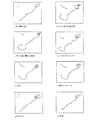
図7に図6に示した反射波期間取り出し結合波形を用いて、埋め込み次元は2、遅れ時間τ=3サンプルを採用したアトラクタを示す。遅れ時間τ=3サンプルとは3つ後のpパルスのサンプリング時の数値を使用する意味であり、遅れ時間τ=3サンプル期間にアトラクタに最も変化が表れたものである。 FIG. 7 shows an attractor employing the reflected wave period extraction combined waveform shown in FIG. 6 and employing an embedding dimension of 2 and a delay time τ = 3 samples. The delay time τ = 3 samples means that the numerical value at the time of sampling of the third p pulse is used, and the change appears most in the attractor during the delay time τ = 3 sample periods.
図7(a)は測定対象物が何も置かれていない場合、図7(b)は乾燥状態のボード紙、図7(c)は濡れた状態のボード紙、図7(d)はアルミニウムシート、図7(e)は木板、図7(f)は発泡スチロール、図7(g)葉キャベツ、図7(h)は大根のアトラクタを示している。このアトラクタは左下部分および右上部分に材質による弾性特性の変化が著しく現れている。アトラクタの変化を定量化するにはアトラクタの穴の数、巻き数、さらには3次元表示したときの図形の体積などが考えられる。 FIG. 7A shows a case where no measurement object is placed, FIG. 7B shows a dry board, FIG. 7C shows a wet board, and FIG. 7D shows aluminum. 7 (e) shows a wooden board, FIG. 7 (f) shows a polystyrene foam, FIG. 7 (g) a leaf cabbage, and FIG. 7 (h) shows a radish attractor. In this attractor, changes in elastic properties due to the material remarkably appear in the lower left part and the upper right part. In order to quantify the change of the attractor, the number of holes of the attractor, the number of windings, and the volume of the figure when three-dimensionally displayed can be considered.
材質の柔らかさを基準に考えると、濡れた状態のボード紙>キャベツ>アルミニウムシート>発泡スチロール>大根>乾燥状態のボード紙>木板の順番であるが、アトラクタは
柔らかいほど右上部分に表れる巻き数が多くなることが分かる。また、左下部分の巻きの大きさにも材質の柔らかさに応じて変化が出ている。
Considering the softness of the material as a standard, the board is in the order of wet board paper, cabbage, aluminum sheet, polystyrene foam, radish, dry board paper, and wood board. You can see that it increases. In addition, the winding size of the lower left part also changes depending on the softness of the material.
本発明は音波を測定対象物に投射して得られる振動による非線形弾性特性を測定することで、野菜の湿度、温度など保存条件による鮮度測定、遮音建材の湿度、温度、日射など環境条件に対する特性変化測定、可塑材料の熱特性の測定、人の皮膚の老化診断など、広く弾性特性を持つ素材の特性変化測定、診断に適用できる。 The present invention measures non-linear elastic characteristics due to vibration obtained by projecting sound waves onto a measurement object, thereby measuring freshness measurement under storage conditions such as vegetable humidity and temperature, and characteristics with respect to environmental conditions such as humidity, temperature and solar radiation of sound insulation building materials. It can be applied to the measurement and diagnosis of material properties with a wide range of elastic properties such as change measurement, measurement of thermal properties of plastic materials, and aging diagnosis of human skin.
1・・・測定対象物(たとえば、建材ボード)
2・・・スピーカー
3・・・マイクロフォン
4・・・遮音ボックス
5・・・遮音隔壁
6・・・発振器
7・・・測定対象物への投射音
8・・・測定対象物からの反射音
9・・・アナログ・デジタル変換器
10・・パソコン
11・・位相遅延器(遅延時間τ秒)
12・・受音信号
13・・受音信号よりτ秒遅らさせた信号
14・・信号表示用直交座標画面の横軸(X軸)
15・・信号表示用直交座標画面の縦軸(Y軸)
16・・アトラクタを表示する信号変化の軌道図形
1. Measurement object (for example, building material board)
DESCRIPTION OF SYMBOLS 2 ...
12 ....
15 .. Vertical axis (Y axis) of Cartesian coordinate screen for signal display
16 .... Orbital figure of signal change to display attractor
Claims (5)
該測定対象物に離間して配置され可聴周波数の音波を出力するスピーカーと、
前記測定対象物からの反射音を収集するマイクロフォンとを備え、
前記マイクロフォンからの反射音をAD変換して、カオティックな非周期的変化の図形を表示装置に表示して非接触測定により測定対象物の弾性特性を測定することを特徴とする音波を用いた弾性特性の測定方法。 An object to be measured for elasticity characteristics;
A speaker that is spaced apart from the object to be measured and outputs sound waves having an audible frequency;
A microphone that collects reflected sound from the measurement object;
Elasticity using sound waves, characterized in that the reflected sound from the microphone is AD-converted, a chaotic non-periodic change figure is displayed on a display device, and the elastic characteristic of the measurement object is measured by non-contact measurement How to measure characteristics.
Priority Applications (1)
| Application Number | Priority Date | Filing Date | Title |
|---|---|---|---|
| JP2006286898A JP2007192801A (en) | 2005-12-19 | 2006-10-20 | Measuring method of elasticity using sound wave |
Applications Claiming Priority (2)
| Application Number | Priority Date | Filing Date | Title |
|---|---|---|---|
| JP2005364272 | 2005-12-19 | ||
| JP2006286898A JP2007192801A (en) | 2005-12-19 | 2006-10-20 | Measuring method of elasticity using sound wave |
Publications (1)
| Publication Number | Publication Date |
|---|---|
| JP2007192801A true JP2007192801A (en) | 2007-08-02 |
Family
ID=38448603
Family Applications (1)
| Application Number | Title | Priority Date | Filing Date |
|---|---|---|---|
| JP2006286898A Pending JP2007192801A (en) | 2005-12-19 | 2006-10-20 | Measuring method of elasticity using sound wave |
Country Status (1)
| Country | Link |
|---|---|
| JP (1) | JP2007192801A (en) |
Cited By (4)
| Publication number | Priority date | Publication date | Assignee | Title |
|---|---|---|---|---|
| CN101806778A (en) * | 2010-03-05 | 2010-08-18 | 北京工业大学 | Method for non-linear ultrasonic online detection of early fatigue damage to metal material |
| WO2013061949A1 (en) | 2011-10-25 | 2013-05-02 | Kurosawa Ryo | Medical treatment device and medical treatment method |
| JP2018114244A (en) * | 2017-01-20 | 2018-07-26 | 花王株式会社 | Skin condition evaluation method |
| JP2018114246A (en) * | 2017-01-20 | 2018-07-26 | 花王株式会社 | Skin condition evaluation method |
-
2006
- 2006-10-20 JP JP2006286898A patent/JP2007192801A/en active Pending
Cited By (4)
| Publication number | Priority date | Publication date | Assignee | Title |
|---|---|---|---|---|
| CN101806778A (en) * | 2010-03-05 | 2010-08-18 | 北京工业大学 | Method for non-linear ultrasonic online detection of early fatigue damage to metal material |
| WO2013061949A1 (en) | 2011-10-25 | 2013-05-02 | Kurosawa Ryo | Medical treatment device and medical treatment method |
| JP2018114244A (en) * | 2017-01-20 | 2018-07-26 | 花王株式会社 | Skin condition evaluation method |
| JP2018114246A (en) * | 2017-01-20 | 2018-07-26 | 花王株式会社 | Skin condition evaluation method |
Similar Documents
| Publication | Publication Date | Title |
|---|---|---|
| US8300840B1 (en) | Multiple superimposed audio frequency test system and sound chamber with attenuated echo properties | |
| JP5606234B2 (en) | Sound equipment | |
| EP1605258A3 (en) | Device and method for sonic inspection of micro structures | |
| JP2007192801A (en) | Measuring method of elasticity using sound wave | |
| CN104215694A (en) | Acoustic insulation testing device for fabric | |
| JP2006349628A (en) | Quality evaluation device for concrete structure and quality evaluation method for concrete structure | |
| Kastelein et al. | Hearing thresholds of a harbor porpoise (Phocoena phocoena) for sweeps (1–2 kHz and 6–7 kHz bands) mimicking naval sonar signals | |
| US6728661B1 (en) | Nondestructive acoustic method and device, for the determination of detachments of mural paintings | |
| JP2019196973A (en) | Non-contact acoustic analysis system and non-contact acoustic analysis method | |
| Del Vescovo et al. | Assessment of fresco detachments through a non-invasive acoustic method | |
| JP6886890B2 (en) | Decay time analysis methods, instruments, and programs | |
| JP2004333199A (en) | Apparatus and method for determining abnormal sound | |
| JP4899049B2 (en) | Method and apparatus for measuring the viscosity of fruits and vegetables | |
| JP2007333545A (en) | Sound absorption characteristic measuring method and sound absorption characteristic measuring apparatus | |
| EP2913644A2 (en) | Portable device for measuring the acoustic reflectivity coefficient in situ | |
| Brandon et al. | An experimental investigation into the topological stability of a cracked cantilever beam | |
| Bogomolov et al. | Analysis of the uncertainty of acoustic measurements at various angles of incidence of acoustic waves on a measuring microphone | |
| Bietz et al. | Investigations to determine the dynamic stiffness of elastic insulating materials | |
| JP2002054999A (en) | Sound wave generation detecting device, environmental state measuring device and method | |
| JP2004333200A (en) | Apparatus and method for determining abnormal sound and program | |
| WO2023210083A1 (en) | Abnormality detection device, abnormality detection method, and program | |
| Mahn et al. | Measurement of the airborne and resonant radiation efficiencies | |
| Jacobsen | Sound intensity and its measurement | |
| JP2021081212A (en) | Diagnosis method for structure | |
| Haac et al. | Experimental characterization of the vibro-acoustic response of a simple residential structure to a simulated sonic boom |