JP2007192015A - Sliding door structure - Google Patents
Sliding door structure Download PDFInfo
- Publication number
- JP2007192015A JP2007192015A JP2006315128A JP2006315128A JP2007192015A JP 2007192015 A JP2007192015 A JP 2007192015A JP 2006315128 A JP2006315128 A JP 2006315128A JP 2006315128 A JP2006315128 A JP 2006315128A JP 2007192015 A JP2007192015 A JP 2007192015A
- Authority
- JP
- Japan
- Prior art keywords
- door
- sliding door
- slide
- vehicle body
- link arm
- Prior art date
- Legal status (The legal status is an assumption and is not a legal conclusion. Google has not performed a legal analysis and makes no representation as to the accuracy of the status listed.)
- Pending
Links
Images


Abstract
Description
本発明は、スライドドア構造に係り、特に、リンクアームの揺動によって車体に設けられたドア開口を開閉するスライドドアを備えたスライドドア構造に関する。 The present invention relates to a slide door structure, and more particularly to a slide door structure including a slide door that opens and closes a door opening provided in a vehicle body by swinging a link arm.
この種のスライドドア構造としては、次のものが知られている(例えば、特許文献1参照)。例えば、特許文献1には、トラック等の車両に設けられたスライドドア構造の例が開示されている。この特許文献1に記載の例では、アームの車体側がベースを介して車体に固定され、アームのドア側がスライドレールを介してスライドドアに固定されている。そして、このスライドドアの車体への取り付けは、次のように行われる。 As this kind of sliding door structure, the following is known (for example, refer to Patent Document 1). For example, Patent Document 1 discloses an example of a sliding door structure provided in a vehicle such as a truck. In the example described in Patent Document 1, the vehicle body side of the arm is fixed to the vehicle body via the base, and the door side of the arm is fixed to the slide door via the slide rail. The sliding door is attached to the vehicle body as follows.
すなわち、アームの車体側をベースを介して車体に固定し、アームのドア側にスライドレールを取り付ける。そして、スライドドアを開方向にスライドさせた位置で保持し、この状態で、スライドレールとスライドドアとの位置調整、すなわち、スライドドアの建て付け調整を行い、その後、スライドレールをスライドドアの車室側(車両幅方向内側)からスライドドアに固定してスライドドアを車体に取り付ける。
しかしながら、特許文献1に記載の例では、上述の如く、スライドレールをスライドドアの車室側(車両幅方向内側)から固定する構成であるため、スライドドアの建て付け調整はスライドドアを開方向にスライドさせた状態で行う必要がありスライドドアを車体に閉じた状態で行うことができなかった。従って、スライドドアの建て付け調整後に、スライドドアを車体に閉じた状態としてスライドドアの建て付け確認を行い、このときにスライドドアが車体に対して所望の位置に取り付けられていないことが判明した場合には、再度のスライドドアの建て付け調整が必要であった。 However, in the example described in Patent Document 1, as described above, the slide rail is configured to be fixed from the vehicle interior side (the vehicle width direction inner side) of the slide door. The sliding door must be slid into the vehicle body, and the sliding door cannot be performed with the vehicle body closed. Therefore, after adjusting the installation of the sliding door, the sliding door was confirmed to be installed with the sliding door closed to the vehicle body. At this time, it was found that the sliding door was not attached at the desired position with respect to the vehicle body. In some cases, it was necessary to re-adjust the sliding door.
このため、特許文献1に記載の例の如く、スライドレールをスライドドアの車室側(車両幅方向内側)から固定する構成とした場合には、スライドドアが車体に対して所望の位置に取り付けられるまで、スライドドアの建て付け調整と建て付け確認との試行錯誤の繰り返しとなる虞がある。従って、スライドドアの車体への建て付け作業性を向上させるためには改善の余地がある。 Therefore, as in the example described in Patent Document 1, when the slide rail is configured to be fixed from the passenger compartment side (vehicle width direction inner side) of the slide door, the slide door is attached to a desired position with respect to the vehicle body. Until then, there is a risk of repeated trial and error between the adjustment of the sliding door and the confirmation of the installation. Therefore, there is room for improvement in order to improve the workability of installing the sliding door on the vehicle body.
本発明は、上記事情に鑑みてなされたものであって、その目的は、スライドドアの車体への建て付け作業性を向上させることが可能なスライドドア構造を提供することにある。 This invention is made | formed in view of the said situation, The objective is to provide the sliding door structure which can improve the workability | operativity of the installation to the vehicle body of a sliding door.
前記課題を解決するために、請求項1に記載のスライドドア構造は、一端側が車体に回動自在に連結されたリンクアームと、前記リンクアームの他端側がドアヒンジを介して回動自在に取り付けられ、前記リンクアームの揺動によって前記車体に設けられたドア開口を開閉するスライドドアと、前記スライドドアと前記車体との位置調整及び固定を前記スライドドアのドア厚さ方向外側から可能とする固定手段と、を備えることを特徴とする。 In order to solve the above-mentioned problem, the sliding door structure according to claim 1, wherein one end side is pivotally connected to the vehicle body, and the other end side of the link arm is pivotally attached via a door hinge. A sliding door that opens and closes a door opening provided in the vehicle body by swinging the link arm, and position adjustment and fixing of the sliding door and the vehicle body can be performed from the outside in the thickness direction of the sliding door. And a fixing means.
なお、この場合に、スライドドアのドア厚さ方向とは、例えば、スライドドアが車両の側面に設けられた場合には、車両幅方向に相当し、スライドドアが車両の背面に設けられた場合には、車両前後方向に相当する。 In this case, the door thickness direction of the sliding door corresponds to the vehicle width direction when the sliding door is provided on the side surface of the vehicle, for example, and the sliding door is provided on the rear surface of the vehicle. Corresponds to the vehicle longitudinal direction.
請求項1に記載のスライドドア構造において、スライドドアを車体に取り付けるには、例えば、先ず、リンクアームの車体側を車体に回動自在に連結し、リンクアームの他端側にドアヒンジを設け、このドアヒンジにスライドドアを固定する。このとき、例えば、リンクアームと車体との位置調整若しくはドアヒンジとスライドドアとの位置調整を行うことでスライドドアと車体との位置調整を行い、この位置調整後に各部の固定を行うことでスライドドアが車体に固定される。 In order to attach the slide door to the vehicle body, for example, first, the vehicle body side of the link arm is rotatably connected to the vehicle body, and a door hinge is provided on the other end side of the link arm. A sliding door is fixed to this door hinge. At this time, for example, by adjusting the position of the link arm and the vehicle body, or adjusting the position of the door hinge and the slide door, the position of the slide door and the vehicle body is adjusted. Is fixed to the car body.
ここで、請求項1に記載のスライドドア構造では、上述のスライドドアと車体との位置調整及び固定を固定手段で行い得るように構成されており、この固定手段は、スライドドアと車体との位置調整及び固定をスライドドアのドア厚さ方向外側から可能とする構成とされている。この構成によれば、スライドドアを車体側に閉じた状態としても、スライドドアと車体との位置調整及び固定をスライドドアのドア厚さ方向外側から行うことができるので、これにより、スライドドアの建て付け作業(スライドドアの建て付け調整を含む)を、スライドドアを車体側に閉じた状態で行うことが可能となる。 Here, the sliding door structure according to claim 1 is configured such that the position adjustment and fixing between the sliding door and the vehicle body can be performed by a fixing means, and the fixing means is provided between the sliding door and the vehicle body. The position adjustment and fixing can be performed from the outside in the thickness direction of the sliding door. According to this configuration, even when the sliding door is closed to the vehicle body side, position adjustment and fixing of the sliding door and the vehicle body can be performed from the outside in the thickness direction of the sliding door. Installation work (including installation adjustment of the slide door) can be performed with the slide door closed on the vehicle body side.
つまり、この種のリンクアームの揺動によってスライドドアをスライドさせるスライドドア構造では、スライドドアの開き角度に応じてリンクアームに対するスライドドアの重心位置が変化し、このことによってリンクアームのスライドドアの重心位置に対するモーメントアーム長が変化する。このため、スライドドアの開き角度、すなわち、スライドドアの重心位置の変化に応じてリンクアーム(若しくはリンクアーム及びドアヒンジ)が変形する場合がある。従って、この種のスライドドア構造において、スライドドアの建て付け調整を、スライドドアを開方向にスライドさせた状態で行うと、リンクアームの変形(若しくはリンクアーム及びドアヒンジの変形)に応じたスライドドアの建て付け調整が必要となる場合があるので、スライドドアの建て付け作業は、スライドドアを車体側に閉じた状態として行うのが望ましい。 That is, in this type of sliding door structure in which the sliding door is slid by swinging the link arm, the position of the center of gravity of the sliding door with respect to the link arm changes according to the opening angle of the sliding door. The moment arm length with respect to the position of the center of gravity changes. For this reason, the link arm (or the link arm and the door hinge) may be deformed in accordance with a change in the opening angle of the slide door, that is, the position of the center of gravity of the slide door. Therefore, in this type of sliding door structure, when the sliding door is adjusted in the state where the sliding door is slid in the opening direction, the sliding door according to the deformation of the link arm (or the deformation of the link arm and door hinge). Therefore, it is desirable that the sliding door is built with the sliding door closed on the vehicle body side.
また、例えば、スライドドアの下部にリンクアームを配置し、スライドドアのリンクアームが設けられた部分よりも上側にドアロック部(ストライカ及びラッチ)を配置した構成としたときには、スライドドアのリンクアーム取付部とドアロック部とが上下に離間することに伴って、スライドドア本体、すなわち、スライドドアのリンクアーム取付部とドアロック部間に変形が生ずる場合がある。従って、この構成の場合も、スライドドアの建て付け調整を、スライドドアを開方向にスライドさせた状態で行うと、スライドドアのリンクアーム取付部とドアロック部間の変形、すなわち、スライドドア本体の変形に応じたスライドドアの建て付け調整が必要となる場合があるので、この点からも、スライドドアの建て付け作業は、スライドドアを車体側に閉じた状態として行うのが望ましい。 In addition, for example, when the link arm is arranged at the lower part of the slide door and the door lock portion (striker and latch) is arranged above the part where the link arm of the slide door is provided, the link arm of the slide door As the mounting portion and the door lock portion are separated from each other vertically, deformation may occur between the slide door body, that is, the link arm mounting portion and the door lock portion of the slide door. Therefore, even in this configuration, if the sliding door is adjusted in the state in which the sliding door is slid in the opening direction, deformation between the link arm mounting portion and the door lock portion of the sliding door, that is, the sliding door main body is performed. Since it may be necessary to adjust the sliding door according to the deformation of the sliding door, it is desirable that the sliding door is built with the sliding door closed on the vehicle body side.
従って、請求項1に記載のスライドドア構造のように、スライドドアと車体との位置調整及び固定をスライドドアのドア厚さ方向外側から可能とする構成として、スライドドアの建て付け作業を、スライドドアを車体側に閉じた状態で行えるようにすれば、リンクアームの変形(若しくはリンクアーム及びドアヒンジの変形)及びスライドドアのリンクアーム取付部とドアロック部間の変形(すなわち、スライドドア本体の変形)の影響を排除してスライドドアの建て付け調整を行うことが可能となる。これにより、スライドドアの建て付け精度を向上させることが可能となる。 Therefore, as in the slide door structure according to claim 1, the slide door is constructed in such a manner that the slide door and the vehicle body can be adjusted and fixed from the outside in the thickness direction of the slide door. If the door can be closed in the vehicle body side, the link arm can be deformed (or the link arm and door hinge can be deformed) and the link arm mounting portion of the sliding door can be deformed between the door lock portion (that is, the sliding door body It is possible to eliminate the influence of the deformation) and adjust the sliding door. Thereby, it becomes possible to improve the installation accuracy of a slide door.
また、上述の如く、スライドドアの建て付け作業を、スライドドアを車体側に閉じた状態で行えるようにすれば、スライドドアと車体との位置を直接的に確認しながら(つまり建て付け確認しながら)、スライドドアの車体への建て付け調整を行うことができる。これにより、スライドドアの建て付け調整と建て付け確認との試行錯誤の繰り返しを防止できるので、スライドドアの車体への建て付け作業性も向上させることが可能となる。 In addition, as described above, if the sliding door can be built while the sliding door is closed to the vehicle body side, the position of the sliding door and the vehicle body can be confirmed directly (that is, the building confirmation can be confirmed). However, it is possible to adjust the installation of the sliding door on the body. As a result, it is possible to prevent repeated trial and error between the installation adjustment of the sliding door and the confirmation of the installation, so that the workability of installing the sliding door on the vehicle body can be improved.
また、前記課題を解決するために、請求項2に記載のスライドドア構造は、一端側が車体に回動自在に連結されたリンクアームと、前記リンクアームの他端側がドアヒンジを介して回動自在に取り付けられ、前記リンクアームの揺動によって前記車体に設けられたドア開口を開閉するスライドドアと、前記スライドドアと前記ドアヒンジとの位置調整及び固定を前記スライドドアのドア厚さ方向外側から可能とする固定手段と、を備えることを特徴とする。 In order to solve the above-mentioned problem, the sliding door structure according to claim 2 has a link arm whose one end is rotatably connected to the vehicle body, and the other end of the link arm is freely rotatable via a door hinge. The slide door that opens and closes the door opening provided in the vehicle body by swinging the link arm, and the slide door and the door hinge can be adjusted and fixed from the outside in the thickness direction of the slide door. And fixing means.
なお、この場合に、スライドドアのドア厚さ方向とは、例えば、スライドドアが車両の側面に設けられた場合には、車両幅方向に相当し、スライドドアが車両の背面に設けられた場合には、車両前後方向に相当する。 In this case, the door thickness direction of the sliding door corresponds to the vehicle width direction when the sliding door is provided on the side surface of the vehicle, for example, and the sliding door is provided on the rear surface of the vehicle. Corresponds to the vehicle longitudinal direction.
請求項2に記載のスライドドア構造において、スライドドアを車体に取り付けるには、例えば、先ず、リンクアームの車体側を車体に回動自在に連結し、リンクアームの他端側にドアヒンジを設け、このドアヒンジにスライドドアを固定手段により固定する。 In the sliding door structure according to claim 2, in order to attach the sliding door to the vehicle body, for example, first, the vehicle body side of the link arm is rotatably connected to the vehicle body, and a door hinge is provided on the other end side of the link arm, A sliding door is fixed to the door hinge by a fixing means.
ここで、請求項2に記載のスライドドア構造では、上述のドアヒンジにスライドドアを固定するための固定手段は、スライドドアとドアヒンジとの位置調整及び固定をスライドドアのドア厚さ方向外側から可能とする構成とされている。この構成によれば、スライドドアを車体側に閉じた状態としても、スライドドアとドアヒンジとの位置調整及び固定をスライドドアのドア厚さ方向外側から行うことができるので、これにより、スライドドアの建て付け作業(スライドドアの建て付け調整を含む)を、スライドドアを車体側に閉じた状態で行うことが可能となる。 Here, in the sliding door structure according to claim 2, the fixing means for fixing the sliding door to the door hinge described above can adjust and fix the position of the sliding door and the door hinge from the outside in the thickness direction of the sliding door. It is set as the structure. According to this configuration, even when the sliding door is closed to the vehicle body side, position adjustment and fixing of the sliding door and the door hinge can be performed from the outside in the thickness direction of the sliding door. Installation work (including installation adjustment of the slide door) can be performed with the slide door closed on the vehicle body side.
つまり、この種のリンクアームの揺動によってスライドドアをスライドさせるスライドドア構造では、スライドドアの開き角度に応じてリンクアームに対するスライドドアの重心位置が変化し、このことによってリンクアームのスライドドアの重心位置に対するモーメントアーム長が変化する。このため、スライドドアの開き角度、すなわち、スライドドアの重心位置の変化に応じてリンクアーム(若しくはリンクアーム及びドアヒンジ)が変形する場合がある。従って、この種のスライドドア構造において、スライドドアの建て付け調整を、スライドドアを開方向にスライドさせた状態で行うと、リンクアームの変形(若しくはリンクアーム及びドアヒンジの変形)に応じたスライドドアの建て付け調整が必要となる場合があるので、スライドドアの建て付け作業は、スライドドアを車体側に閉じた状態として行うのが望ましい。 That is, in this type of sliding door structure in which the sliding door is slid by swinging the link arm, the position of the center of gravity of the sliding door with respect to the link arm changes according to the opening angle of the sliding door. The moment arm length with respect to the position of the center of gravity changes. For this reason, the link arm (or the link arm and the door hinge) may be deformed in accordance with a change in the opening angle of the slide door, that is, the position of the center of gravity of the slide door. Therefore, in this type of sliding door structure, when the sliding door is adjusted in the state where the sliding door is slid in the opening direction, the sliding door according to the deformation of the link arm (or the deformation of the link arm and door hinge). Therefore, it is desirable that the sliding door is built with the sliding door closed on the vehicle body side.
また、例えば、スライドドアの下部にリンクアームを配置し、スライドドアのリンクアームが設けられた部分よりも上側にドアロック部(ストライカ及びラッチ)を配置した構成としたときには、スライドドアのリンクアーム取付部とドアロック部とが上下に離間することに伴って、スライドドア本体、すなわち、スライドドアのリンクアーム取付部とドアロック部間に変形が生ずる場合がある。従って、この構成の場合も、スライドドアの建て付け調整を、スライドドアを開方向にスライドさせた状態で行うと、スライドドアのリンクアーム取付部とドアロック部間の変形、すなわち、スライドドア本体の変形に応じたスライドドアの建て付け調整が必要となる場合があるので、この点からも、スライドドアの建て付け作業は、スライドドアを車体側に閉じた状態として行うのが望ましい。 In addition, for example, when the link arm is arranged at the lower part of the slide door and the door lock portion (striker and latch) is arranged above the part where the link arm of the slide door is provided, the link arm of the slide door As the mounting portion and the door lock portion are separated from each other vertically, deformation may occur between the slide door body, that is, the link arm mounting portion and the door lock portion of the slide door. Therefore, even in this configuration, if the sliding door is adjusted in the state in which the sliding door is slid in the opening direction, deformation between the link arm mounting portion and the door lock portion of the sliding door, that is, the sliding door main body is performed. Since it may be necessary to adjust the sliding door according to the deformation of the sliding door, it is desirable that the sliding door is built with the sliding door closed on the vehicle body side.
従って、請求項2に記載のスライドドア構造のように、スライドドアとドアヒンジとの位置調整及び固定をスライドドアのドア厚さ方向外側から可能とする構成として、スライドドアの建て付け作業を、スライドドアを車体側に閉じた状態で行えるようにすれば、リンクアームの変形(若しくはリンクアーム及びドアヒンジの変形)及びスライドドアのリンクアーム取付部とドアロック部間の変形(すなわち、スライドドア本体の変形)の影響を排除してスライドドアの建て付け調整を行うことが可能となる。これにより、スライドドアの建て付け精度を向上させることが可能となる。 Therefore, as in the slide door structure according to claim 2, the slide door is constructed in such a manner that the slide door and the door hinge can be adjusted and fixed from the outside in the thickness direction of the slide door. If the door can be closed in the vehicle body side, the link arm can be deformed (or the link arm and door hinge can be deformed) and the link arm mounting portion of the sliding door can be deformed between the door lock portion (that is, the sliding door body It is possible to eliminate the influence of the deformation) and adjust the sliding door. Thereby, it becomes possible to improve the installation accuracy of a slide door.
また、上述の如く、スライドドアの建て付け作業を、スライドドアを車体側に閉じた状態で行えるようにすれば、スライドドアと車体との位置を直接的に確認しながら(つまり建て付け確認しながら)、スライドドアの車体への建て付け調整を行うことができる。これにより、スライドドアの建て付け調整と建て付け確認との試行錯誤の繰り返しを防止できるので、スライドドアの車体への建て付け作業性も向上させることが可能となる。 In addition, as described above, if the sliding door can be built while the sliding door is closed to the vehicle body side, the position of the sliding door and the vehicle body can be confirmed directly (that is, the building confirmation can be confirmed). However, it is possible to adjust the installation of the sliding door on the body. As a result, it is possible to prevent repeated trial and error between the installation adjustment of the sliding door and the confirmation of the installation, so that the workability of installing the sliding door on the vehicle body can be improved.
請求項3に記載の発明は、請求項1又は請求項2に記載のスライドドア構造において、前記スライドドアは、ドア厚さ方向内側に前記ドアヒンジが取り付けられるインナパネルと、前記インナパネルのドア厚さ方向外側に設けられたアウタパネルと、を備え、前記固定手段は、前記インナパネルの前記ドアヒンジの取付部に板厚方向に貫通形成された固定孔に遊挿されると共に前記インナパネルの前記固定孔の周縁部と前記ドアヒンジとを固定し且つ前記アウタパネルに板厚方向に貫通形成された作業孔によってドア厚さ方向外側に露出された固定具を有して構成されていることを特徴とする。 According to a third aspect of the present invention, in the slide door structure according to the first or second aspect, the slide door includes an inner panel to which the door hinge is attached on the inner side in the door thickness direction, and a door thickness of the inner panel. An outer panel provided on the outer side in the vertical direction, and the fixing means is loosely inserted into a fixing hole formed through the attachment portion of the door hinge of the inner panel in the plate thickness direction and the fixing hole of the inner panel And a fixing tool exposed to the outer side in the thickness direction of the outer panel by a work hole penetratingly formed in the thickness direction of the outer panel.
請求項3に記載のスライドドア構造では、スライドドアとドアヒンジとの位置調整及び固定、すなわち、スライドドアの車体への建て付け作業を次のようにして行うことができる。すなわち、例えば、スライドドアを車体側に閉じた状態とし、インナパネルのドアヒンジの取付部にドアヒンジを位置させる。続いて、ドア厚さ方向外側からアウタパネルの作業孔を介して固定具をスライドドアの内部に進入させ、インナパネルの固定孔に固定具を挿入する。このとき、固定具は固定孔に遊挿状態となるので、スライドドアとドアヒンジとの位置調整、つまり、スライドドアの建て付け調整を行うことができる。そして、スライドドアの建て付け調整の完了と共にインナパネルの固定孔の周縁部とドアヒンジとを固定具により固定しスライドドアの車体への建て付け作業を完了する。 In the sliding door structure according to the third aspect, the position adjustment and fixing of the sliding door and the door hinge, that is, the building operation of the sliding door on the vehicle body can be performed as follows. That is, for example, the sliding door is closed to the vehicle body side, and the door hinge is positioned on the door hinge mounting portion of the inner panel. Subsequently, the fixing tool is caused to enter the inside of the sliding door from the outside in the door thickness direction through the work hole of the outer panel, and the fixing tool is inserted into the fixing hole of the inner panel. At this time, since the fixing tool is loosely inserted into the fixing hole, the position adjustment between the slide door and the door hinge, that is, the installation adjustment of the slide door can be performed. Then, along with the completion of the installation adjustment of the slide door, the peripheral portion of the fixing hole of the inner panel and the door hinge are fixed by the fixing tool, and the installation operation of the slide door to the vehicle body is completed.
このように、請求項3に記載のスライドドア構造によれば、スライドドアを車体側に閉じた状態としても、スライドドアのドア厚さ方向外側からスライドドアとドアヒンジとの位置調整及び固定を行うことでスライドドアの車体への建て付け作業(スライドドアの建て付け調整を含む)を容易に行うことが可能である。 Thus, according to the sliding door structure of the third aspect, even when the sliding door is closed to the vehicle body side, the position adjustment and fixing of the sliding door and the door hinge are performed from the outside in the thickness direction of the sliding door. Thus, it is possible to easily perform the building operation of the sliding door on the vehicle body (including the adjustment of the sliding door).
請求項4に記載の発明は、請求項1乃至請求項3のいずれか一項に記載のスライドドア構造において、前記固定手段は、前記リンクアームと同一高さに配置されていることを特徴とする。 According to a fourth aspect of the present invention, in the slide door structure according to any one of the first to third aspects, the fixing means is disposed at the same height as the link arm. To do.
請求項4に記載のスライドドア構造では、固定手段がリンクアームと同一高さに配置されることで、スライドドアがリンクアームと同一高さの位置で車体(例えばドアヒンジ)に固定されている。従って、スライドドアの車体との固定部とリンクアームの上下中心部とのオフセット量を少なくすることができるので、スライドドアの車体との固定部からリンクアームまでの部分の変形の影響を排除して、スライドドアの建て付け調整を行うことが可能となる。これにより、スライドドアの建て付け精度をより向上させることが可能となる。 In the slide door structure according to the fourth aspect, the fixing means is arranged at the same height as the link arm, so that the slide door is fixed to the vehicle body (for example, a door hinge) at the same height as the link arm. Accordingly, the amount of offset between the fixed portion of the sliding door to the vehicle body and the vertical center portion of the link arm can be reduced, thereby eliminating the influence of deformation of the portion from the fixed portion of the sliding door to the vehicle body to the link arm. Thus, it is possible to adjust the installation of the sliding door. Thereby, it becomes possible to improve the installation accuracy of a slide door more.
請求項5に記載の発明は、請求項1乃至請求項4のいずれか一項に記載のスライドドア構造において、前記ドアヒンジには、前記スライドドアのドア高さ方向を向く被当接面が設けられ、前記固定手段には、前記被当接面と当接するカム部及び前記カム部と一体に形成された回転軸部を有し、前記回転軸部が前記スライドドアに回転操作可能に設けられると共に前記スライドドアのドア厚さ方向外側に露出されて構成されたドア高さ調整手段が備えられていることを特徴とする。 According to a fifth aspect of the present invention, in the sliding door structure according to any one of the first to fourth aspects, the door hinge is provided with a contacted surface facing the door height direction of the sliding door. The fixing means includes a cam portion that contacts the abutted surface and a rotation shaft portion that is formed integrally with the cam portion, and the rotation shaft portion is provided on the slide door so as to be rotatable. In addition, a door height adjusting means configured to be exposed to the outside in the thickness direction of the slide door is provided.
請求項5に記載のスライドドア構造では、ドアヒンジにスライドドアのドア高さ方向を向く被当接面が設けられており、固定手段には、ドア高さ調整手段が備えられている。ドア高さ調整手段には、カム部が形成されており、このカム部は、ドアヒンジに設けられた非当接面に当接されている。また、ドア高さ調整手段には、カム部と一体に回転軸部が形成されており、この回転軸部は、スライドドアに回転操作可能に設けられている。従って、例えば、スライドドアとドアヒンジとの固定を仮止めとした状態で、回転軸部を回転操作すれば、この回転軸部と一体に回転するカム部の中心とドアヒンジの非当接面との距離が変更されることにより、ドアヒンジに対してスライドドアのドア高さ方向の位置調整を行うことができる。しかも、回転軸部は、スライドドアのドア厚さ方向外側に露出されているので、スライドドアを車体側に閉じた状態で回転軸部を回転させることによりスライドドアのドア高さ方向の位置調整を行うことができる。 In the sliding door structure according to the fifth aspect, the door hinge is provided with a contact surface facing the door height direction of the sliding door, and the fixing means is provided with a door height adjusting means. A cam portion is formed in the door height adjusting means, and this cam portion is in contact with a non-contact surface provided on the door hinge. Further, the door height adjusting means is formed with a rotating shaft portion integrally with the cam portion, and this rotating shaft portion is provided on the slide door so as to be rotatable. Therefore, for example, if the rotation shaft portion is rotated with the sliding door and the door hinge fixed temporarily, the center of the cam portion rotating integrally with the rotation shaft portion and the non-contact surface of the door hinge By changing the distance, the position of the slide door in the door height direction can be adjusted with respect to the door hinge. Moreover, since the rotating shaft is exposed to the outside of the sliding door in the thickness direction, the position of the sliding door in the height direction can be adjusted by rotating the rotating shaft while the sliding door is closed to the vehicle body. It can be performed.
このように、請求項5に記載のスライドドア構造によれば、スライドドアを車体側に閉じた状態としても、スライドドアのドア厚さ方向外側からスライドドアの車体に対するドア高さ方向への建て付け調整を容易に行うことが可能である。 Thus, according to the sliding door structure of the fifth aspect, even when the sliding door is closed to the vehicle body side, the sliding door is built in the door height direction with respect to the sliding door from the outside in the thickness direction of the sliding door. It is possible to adjust the attachment easily.
請求項6に記載の発明は、請求項1乃至請求項5のいずれか一項に記載のスライドドア構造において、前記リンクアームは、長手方向の長さを変更可能に構成されると共に、前記リンクアームを所望の長手方向の長さに保持するためのリンク長保持手段を有し、前記リンク長保持手段は、前記スライドドアのドア厚さ方向外側に露出されていることを特徴とする。 According to a sixth aspect of the present invention, in the slide door structure according to any one of the first to fifth aspects, the link arm is configured to be capable of changing a length in a longitudinal direction, and the link. Link length holding means for holding the arm at a desired length in the longitudinal direction is provided, and the link length holding means is exposed to the outside in the door thickness direction of the slide door.
請求項6に記載のスライドドア構造では、リンクアームが長手方向に長さを変更可能に構成されている。従って、例えば、スライドドアとリンクアームとを固定してスライドドアを車体側に閉じた状態としても、リンクアームの長手方向の長さが変更されることで、スライドドアを車体に対してドア厚さ方向に位置調整することができる。そして、このリンクアームの長手方向の長さをリンク長保持手段によって保持させることで、スライドドアの車体に対するドア厚さ方向への建て付け調整を完了することができる。しかも、このリンクアームを所望の長手方向の長さに保持するためのリンク長保持手段は、スライドドアのドア厚さ方向外側に露出されているので、スライドドアを車体側に閉じた状態でリンクアームを長手方向の長さに保持する作業を行うことができる。 In the sliding door structure according to the sixth aspect, the link arm is configured to be capable of changing its length in the longitudinal direction. Therefore, for example, even when the slide door and the link arm are fixed and the slide door is closed to the vehicle body side, the length of the link arm in the longitudinal direction is changed, so that the slide door is The position can be adjusted in the vertical direction. And the length adjustment of the longitudinal direction of this link arm is hold | maintained by a link length holding | maintenance means, and the installation adjustment to the door thickness direction with respect to the vehicle body of a slide door can be completed. Moreover, since the link length holding means for holding the link arm at a desired length in the longitudinal direction is exposed to the outside of the sliding door in the thickness direction, the link is made with the sliding door closed on the vehicle body side. The operation | work which hold | maintains an arm to the length of a longitudinal direction can be performed.
このように、請求項6に記載のスライドドア構造によれば、スライドドアを車体側に閉じた状態としても、スライドドアのドア厚さ方向外側からスライドドアの車体に対するドア厚さ方向への建て付け調整を容易に行うことが可能である。 Thus, according to the sliding door structure of the sixth aspect, even when the sliding door is closed to the vehicle body side, the sliding door is built in the door thickness direction from the outside of the sliding door in the door thickness direction. It is possible to adjust the attachment easily.
請求項7に記載の発明は、請求項6に記載のスライドドア構造において、前記リンクアームは、アウタアームと、前記アウタアームに対し長手方向に相対移動可能なインナアームと、を有して構成され、前記リンク長保持手段は、前記アウタアームと前記インナアームとを所望の相対位置に保持可能に構成されていることを特徴とする。 The invention according to claim 7 is the sliding door structure according to claim 6, wherein the link arm includes an outer arm and an inner arm that is movable relative to the outer arm in the longitudinal direction. The link length holding means is configured to hold the outer arm and the inner arm at a desired relative position.
請求項7に記載のスライドドア構造では、リンクアームが、アウタアームと、アウタアームに対し長手方向に相対移動可能なインナアームと、を有して構成されており、このアウタアームとインナアームとがリンク長保持手段によって所望の相対位置に保持されるようになっている。このように、請求項7に記載のスライドドア構造によれば、リンクアームの長手方向の長さを簡単な構成により確実に調整することができる。 In the sliding door structure according to claim 7, the link arm includes an outer arm and an inner arm that can move relative to the outer arm in the longitudinal direction, and the outer arm and the inner arm have a link length. It is held at a desired relative position by the holding means. Thus, according to the sliding door structure of the seventh aspect, the length of the link arm in the longitudinal direction can be reliably adjusted with a simple configuration.
請求項8に記載の発明は、請求項1乃至請求項7のいずれか一項に記載のスライドドア構造において、前記固定手段をドア厚さ方向外側から覆い隠した状態で前記スライドドアに固定された隠蔽手段を備えることを特徴とする。 According to an eighth aspect of the present invention, in the sliding door structure according to any one of the first to seventh aspects, the fixing means is fixed to the sliding door in a state where the fixing means is covered from the outside in the door thickness direction. And a concealing means.
請求項8に記載のスライドドア構造では、隠蔽手段によって固定手段がドア厚さ方向外側から覆い隠された状態とされる。これにより、スライドドアの見栄えが確保される。 In the sliding door structure according to the eighth aspect, the fixing means is covered and hidden from the door thickness direction outside by the concealing means. Thereby, the appearance of the sliding door is ensured.
請求項9に記載の発明は、請求項8に記載のスライドドア構造において、前記隠蔽手段は、前記スライドドアにドア厚さ方向内側から固定されていることを特徴とする。 The invention according to claim 9 is the sliding door structure according to claim 8, wherein the concealing means is fixed to the sliding door from the inside in the door thickness direction.
請求項9に記載のスライドドア構造では、ドア厚さ方向外側から固定手段を隠蔽する隠蔽手段が、ドア厚さ方向内側からスライドドアに固定されている。従って、隠蔽手段とスライドドアとの固定状態をドア厚さ方向外側から解除することが不可となるので、ドア厚さ方向外側から固定手段によるドアヒンジとスライドドアとの固定状態を解除することも不可となる。これにより、ドア厚さ方向外側から固定手段によるドアヒンジとスライドドアとの固定状態を解除することによる盗難等も抑制することが可能となる。 In the sliding door structure according to the ninth aspect, the concealing means for concealing the fixing means from the outside in the door thickness direction is fixed to the sliding door from the inside in the door thickness direction. Therefore, it is impossible to release the fixed state between the concealing means and the sliding door from the outside in the door thickness direction, and it is also impossible to release the fixed state between the door hinge and the sliding door by the fixing means from the outside in the door thickness direction. It becomes. Thereby, it is possible to suppress theft and the like due to the release of the fixed state between the door hinge and the slide door by the fixing means from the outside in the door thickness direction.
以上詳述したように、本発明によれば、スライドドアを車体側に閉じた状態としても、スライドドアと車体との位置調整及び固定をスライドドアのドア厚さ方向外側から行うことができる。従って、スライドドアの建て付け作業を、スライドドアを車体側に閉じた状態で行えるので、スライドドアと車体との位置を直接的に確認しながら(つまり建て付け確認しながら)、スライドドアの車体への建て付け調整を行うことができる。これにより、スライドドアの建て付け調整と建て付け確認との試行錯誤の繰り返しを防止できるので、スライドドアの車体への建て付け作業性を向上させることが可能となる。 As described above in detail, according to the present invention, even when the slide door is closed to the vehicle body side, position adjustment and fixation between the slide door and the vehicle body can be performed from the outside in the thickness direction of the slide door. Therefore, since the sliding door can be built with the sliding door closed to the vehicle body side, the position of the sliding door and the vehicle body can be checked directly (that is, while checking the installation), and the vehicle body of the sliding door can be seen. Can be adjusted to build. As a result, it is possible to prevent trial and error from being repeated for building adjustment of the sliding door and confirmation of the building, so that it is possible to improve the workability of installing the sliding door on the vehicle body.
[第一実施形態]
以下、図1乃至図7を参照しながら、本発明の第一実施形態について説明する。
[First embodiment]
Hereinafter, a first embodiment of the present invention will be described with reference to FIGS. 1 to 7.
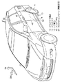
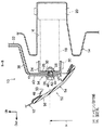
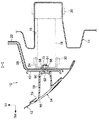
図1には、本発明の第一実施形態に係るスライドドア構造10が適用された車両の全体斜視図が示されており、図2には、図1のA部の拡大図でスライドドア12をスライドさせた状態が示されている。また、図3には、スライドドア構造10及びその周辺部の斜視図が示されており、図4及び図5には、図3のB−B線断面図及びC−C線断面図がそれぞれ示されている。さらに、図6には、スライドドア構造10においてリンクアーム18にドアヒンジ24を取り付けた状態が示されており、図7には、スライドドア構造10においてスライドドア12の建て付け調整を行うためにスライドドア12からプロテクションモール54が取り外された状態が示されている。なお、これらの図において示される矢印Fr、矢印Out、矢印Upは、それぞれ車両前後方向前方側、車両幅方向外側、車両上下方向上側を示している。
FIG. 1 is an overall perspective view of a vehicle to which a sliding
図1に示されるように、本発明の第一実施形態に係る車両において、スライドドア構造10は、車両のリア側面に設けられている。このスライドドア構造10には、スライドドア12が設けられており、このスライドドア12は、後述する一対のリンクアーム18(図2参照)の揺動によって車両前後方向にスライドされる。このスライドドア12をスライドする構成について詳述すると、ドア開口13の下縁を構成するロッカ部14には、図2に示されるように、車両幅方向外側に開口を有する凹部16が車両前後方向に沿って形成されている。この凹部16には、車両前後位置に並設された一対のリンクアーム18の一端側がヒンジピン20(図4,図5参照)によって回動自在に連結されている。
As shown in FIG. 1, in the vehicle according to the first embodiment of the present invention, the sliding
スライドドア12の車室側には、図3のB−B線断面図及びC−C線断面図である図4及び図5に示されるように、インナパネル22が設けられており、このインナパネル22の車室側でロッカ部14と対向する部分には、車両前後方向に沿って形成された断面コの字状のドアヒンジ24が配置されている。このドアヒンジ24には、一対のリンクアーム18の他端側がヒンジピン30によって回動自在に連結されており、スライドドア12は、このリンクアーム18の揺動によって車両前後方向にスライドし、図3に示される車体に設けられたドア開口13を開閉する。
As shown in FIGS. 4 and 5, which are sectional views taken along the line BB and the line CC in FIG. 3, an
そして、図4に示されるように、ドアヒンジ24のインナパネル22との固定壁部26には、固定具としてのドア固定用ボルト46が挿通可能な貫通孔28が板厚方向(車両幅方向)に貫通形成されており、このドアヒンジ24の固定壁部26の車室側面には、貫通孔28と同軸的にウェルドナット32が溶接で固着されている。また、インナパネル22のドアヒンジ取付部34には、上述の貫通孔28と整合する位置に固定孔36が板厚方向(車両幅方向)に貫通形成されており、インナパネル22の車両幅方向外側に設けられたドアインナリインフォースメント38及びドアヒンジリインフォースメント40には、インナパネル22の固定孔36と整合する位置に貫通孔42,44がそれぞれの板厚方向に貫通形成されている。このインナパネル22に形成された固定孔36、ドアインナリインフォースメント38及びドアヒンジリインフォースメント40に形成された貫通孔42,44は、それぞれドア固定用ボルト46が遊挿可能な構成とされている。
As shown in FIG. 4, a through-
なお、このインナパネル22に形成された固定孔36、ドアインナリインフォースメント38及びドアヒンジリインフォースメント40に形成された貫通孔42,44は、それぞれドア固定用ボルト46が遊挿可能な構成とされることにより、後に詳述するように、スライドドア12とドアヒンジ24との位置調整、すなわち、スライドドア12の建て付け調整を可能とするものであり、例えば、車体に対してスライドドア12を位置調整する際の移動代及び移動方向に応じた孔寸法及び孔形状(例えば丸孔、四角孔や、長円や長方形などの長孔等)で構成されている。また、本発明の第一実施形態では、上述のインナパネル22の固定孔36、ドアインナリインフォースメント38及びドアヒンジリインフォースメント40に形成された貫通孔42,44、ドア固定用ボルト46によって固定部52が構成されている。この固定部52は、図3に示されるように、車両前後方向に3箇所設けられている。
The fixing
そして、本発明の第一実施形態では、図4に示されるように、ドアヒンジ24の貫通孔28、インナパネル22の固定孔36、ドアインナリインフォースメント38及びドアヒンジリインフォースメント40の貫通孔42,44を全て整合させた状態で、これらの貫通孔28、固定孔36、貫通孔42,44に車両幅方向外側からドア固定用ボルト46を挿入し、このドア固定用ボルト46をウェルドナット32に螺合することで、ドアヒンジ24、インナパネル22、ドアインナリインフォースメント38及びドアヒンジリインフォースメント40が一体的に固定されている。また、このとき、ドアヒンジ24は、ドア固定用ボルト46及びウェルドナット32によってリンクアーム18と同一高さ(地上からの高さHで一致)の位置でスライドドア12に固定されている。
In the first embodiment of the present invention, as shown in FIG. 4, the through
また、スライドドア12のインナパネル22の車両幅方向外側の部分には、アウタパネル48が設けられている。このアウタパネル48のドア固定用ボルト46の車両幅方向外側の部分には、図3,図5に示されるように、車両側面視にて四角形状の作業孔50(合計3箇所)が板厚方向(車両幅方向)に貫通形成されている。この作業孔50は、車両幅方向外側にドア固定用ボルト46を露出しており、後に詳述するように、車両幅方向外側からドア固定用ボルト46及びウェルドナット32の締結作業を可能としている。なお、この作業孔50は、車両幅方向外側からドア固定用ボルト46をウェルドナット32に螺合するための工具等を挿入可能な程度(つまりドア固定用ボルト46の頭部よりもやや大きい程度)の孔寸法で構成されている。
Further, an
また、スライドドア12の下部には、図3に示されるように、隠蔽手段としてのプロテクションモール54が設けられている。このプロテクションモール54には、ドア固定用ボルト46を車両幅方向外側から一体的に覆い隠すようにスライドドア12の車両前後方向一端側から後端側に延在するモール本体部56が設けられており、このモール本体部56の車両前後方向両端側の部分には、図5に示されるように、車両幅方向内側に延出するボス部58が設けられている。そして、プロテクションモール54は、このボス部58によってスライドドア12に車両幅方向内側から一体的に固定されている。
Further, as shown in FIG. 3, a
つまり、ボス部58は、図5に示されるように、アウタパネル48に設けられた貫通孔59を介してインナパネル22側に延び、このボス部58の延出端部には、ボルト保持部60によってボルト62が保持されている。ボルト62は、ドアヒンジリインフォースメント40、ドアインナリインフォースメント38、インナパネル22に形成された貫通孔64,66,68を介してインナパネル22よりも車両幅方向内側に突出し、このボルト62のインナパネル22より突出した部分には、車両幅方向内側からナット70が螺合されている。本発明の第一実施形態では、このようにしてボルト62にナット70が螺合されることにより、ドアヒンジリインフォースメント40、ドアインナリインフォースメント38、インナパネル22、ボス部58が一体的に固定され、これにより、プロテクションモール54がスライドドア12に車両幅方向内側から一体的に固定されている。
That is, as shown in FIG. 5, the
次に、上記構成からなるスライドドア構造10の作用について説明する。
Next, the operation of the sliding
本発明の第一実施形態に係るスライドドア構造10は、上記各構成により、スライドドア12の車体への建て付け作業(建て付け調整を含む)を、スライドドア12を車体側に閉じた状態で行えるようになっている。以下、これを詳述する。
The sliding
本発明の第一実施形態に係るスライドドア構造10において、スライドドア12を車体に取り付けるには、先ず、図6に示されるように、リンクアーム18の車体側をヒンジピン20により車体に回動自在に連結し、リンクアーム18のドア側にドアヒンジ24を設ける。続いて、以下の要領で、ドアヒンジ24にスライドドア12を固定し、スライドドア12の車体への建て付け作業を行う。
In the sliding
つまり、図7に示されるように、スライドドア12を車体側に閉じた状態とし、図4に示されるインナパネル22のドアヒンジ取付部34にドアヒンジ24を位置させる。続いて、車両幅方向外側からアウタパネル48の作業孔50を介してドア固定用ボルト46をスライドドア12の内部に進入させ、図4に示される如くドアインナリインフォースメント38及びドアヒンジリインフォースメント40の貫通孔42,44を介して、インナパネル22の固定孔36及びドアヒンジ24の貫通孔28にドア固定用ボルト46を挿入する。そして、ドア固定用ボルト46をウェルドナット32に螺合する。なお、このときには、ドア固定用ボルト46とウェルドナット32とを本締めとせずに仮締めとする。
That is, as shown in FIG. 7, the
また、このときには、ドア固定用ボルト46が固定孔36及び貫通孔42,44に対し遊挿状態であるので、これにより、ドア固定用ボルト46が固定孔36及び貫通孔42,44内を移動する範囲内でドアヒンジ24に対してスライドドア12が車両上下方向及び車両前後方向に移動自在となる。従って、この段階で、所定の治具等を用いてスライドドア12とドアヒンジ24との位置調整、つまり、スライドドア12の建て付け調整(例えば、車両上下方向、車両前後方向への調整)を行う。また、このときには、スライドドア12と車体との位置を直接的に確認しながら、すなわち、建て付け確認しながら、スライドドア12の車体への建て付け調整を行う。そして、スライドドア12の建て付け調整の完了と共にドア固定用ボルト46とウェルドナット32とを完全な締結状態とすることによりインナパネル22の固定孔36の周縁部とドアヒンジ24とを固定し、スライドドア12の車体への建て付け作業を完了する。
At this time, since the
そして、図7に示されるように、スライドドア12の下部にプロテクションモール54を位置させ、図5に示されるボス部58のボルト62を、ドアヒンジリインフォースメント40、ドアインナリインフォースメント38、インナパネル22に形成された貫通孔64,66,68を介してインナパネル22よりも車両幅方向内側に突出させる。続いて、このボルト62のインナパネル22より突出した部分に車両幅方向内側からナット70を螺合する。このようにしてボルト62にナット70を螺合することにより、ドアインナリインフォースメント38、ドアヒンジリインフォースメント40、インナパネル22、ボス部58が一体的に固定され、これにより、プロテクションモール54がスライドドア12に車両幅方向内側から一体的に固定される。
Then, as shown in FIG. 7, the
以上詳述したように、本発明の第一実施形態に係るスライドドア構造10によれば、スライドドア12の車両幅方向外側からスライドドア12とドアヒンジ24との位置調整及び固定を可能とすることで、スライドドア12の建て付け作業(スライドドア12の建て付け調整を含む)を、スライドドア12を車体側に閉じた状態で行うことが可能である。
As described above in detail, according to the
つまり、この種のリンクアーム18の揺動によってスライドドア12をスライドさせるスライドドア構造10では、スライドドア12の開き角度に応じてリンクアーム18に対するスライドドア12の重心位置が変化し、このことによってリンクアーム18のスライドドア12の重心位置に対するモーメントアーム長が変化する。このため、スライドドア12の開き角度、すなわち、スライドドア12の重心位置の変化に応じてリンクアーム18(若しくはリンクアーム18及びドアヒンジ24)が変形する場合がある。従って、この種のスライドドア構造10においてスライドドア12の建て付け調整をスライドドア12を開方向にスライドさせた状態で行うと、リンクアーム18の変形(若しくはリンクアーム18及びドアヒンジ24の変形)に応じたスライドドア12の建て付け調整が必要となる場合があるので、スライドドア12の建て付け作業は、スライドドア12を車体側に閉じた状態として行うのが望ましい。
That is, in the
また、例えば、本発明の第一実施形態のように、スライドドア12の下部にリンクアーム18を配置し、スライドドア12のリンクアーム18が設けられた部分よりも上側に図7に示される如くドアロック部72(ストライカ及びラッチ)を配置した構成としたときには、スライドドア12のリンクアーム取付部とドアロック部72とが上下に離間することに伴って、スライドドア12の本体、すなわち、スライドドア12のリンクアーム取付部とドアロック部72間に変形が生ずる場合がある。従って、この構成の場合も、スライドドア12の建て付け調整をスライドドア12を開方向にスライドさせた状態で行うと、スライドドア12のリンクアーム取付部とドアロック部72間の変形、すなわち、スライドドア12の本体の変形に応じたスライドドア12の建て付け調整が必要となる場合があるので、この点からも、スライドドア12の建て付け作業は、スライドドア12を車体側に閉じた状態として行うのが望ましい。
Further, for example, as in the first embodiment of the present invention, as shown in FIG. 7, the
従って、本発明の第一実施形態に係るスライドドア構造10のように、スライドドア12の車両幅方向外側からスライドドア12とドアヒンジ24との位置調整及び固定を可能とすることで、スライドドア12の建て付け作業をスライドドア12を車体側に閉じた状態で行えるようにすれば、リンクアーム18の変形(若しくはリンクアーム18及びドアヒンジ24の変形)及びスライドドア12のリンクアーム取付部とドアロック部72間の変形(すなわち、スライドドア12の本体の変形)の影響を排除してスライドドア12の建て付け調整を行うことが可能となる。これにより、スライドドア12の建て付け精度を向上させることが可能となる。
Therefore, like the
また、上述の如く、スライドドア12の建て付け作業をスライドドア12を車体側に閉じた状態で行えるようにすれば、スライドドア12と車体との位置を直接的に確認しながら、すなわち、建て付け確認しながら、スライドドア12の車体への建て付け調整を行うことができる。これにより、スライドドア12の建て付け調整と建て付け確認との試行錯誤の繰り返しを防止できるので、スライドドア12の車体への建て付け作業性も向上させることができる。
Further, as described above, if the
また、本発明の第一実施形態に係るスライドドア構造10では、上述のように、ドアヒンジ24がリンクアーム18と同一高さの位置(地上からの高さHで一致;図4参照)でドア固定用ボルト46及びウェルドナット32によってスライドドア12に固定されている。従って、スライドドア12のドアヒンジ24との固定部とリンクアーム18の上下中心部とのオフセット量を少なくすることができるので、スライドドア12のドアヒンジ24との固定部からリンクアーム18までの部分の変形の影響を排除して、スライドドア12の建て付け調整を行うことが可能となる。これにより、スライドドア12の建て付け精度をより向上させることが可能となる。
Further, in the sliding
また、上述のように、スライドドア12の建て付け精度が向上することにより、スライドドア12とボディパネルとのオープニング(隙間)を狭くすることができる。従って、オープニングが狭くなることで外観上品質の高い見栄えとすることができるので、これにより、車両側面の高品質化も図ることができる。
Moreover, as described above, the opening accuracy (gap) between the
また、ドアヒンジ24とスライドドア12の取付ピッチ(つまり図3に示される固定部52の車両前後方向の間隔)が短い場合、このスライドドア12のドアヒンジ取付部34から離れた部位では固定部52の取付誤差が拡大されるのでスライドドア12の建て付け精度に影響が生じることが考えられるが、本発明の第一実施形態のように、スライドドア12の建て付け作業をスライドドア12を車体側に閉じた状態で行えるようにすれば、ドアヒンジ24とスライドドア12の取付ピッチが短くても、スライドドア12のドアヒンジ取付部34から離れた部位での固定部52の取付誤差の影響を排除することができる。これにより、スライドドア12の建て付け精度の向上のために、ドアヒンジ24とスライドドア12の取付ピッチに設計上の制約が生じることも抑制できる(つまり無理に取付ピッチを広げる必要が無く、取付ピッチは狭くても良いので設計の自由度が向上する)。
Further, when the mounting pitch between the
また、本発明の第一実施形態に係るスライドドア構造10では、プロテクションモール54によって車両外側から作業孔50を介してドア固定用ボルト46の固定部分が見える箇所が車両幅方向外側から覆い隠された状態とされる。これにより、スライドドア12の見栄えが確保される。
Further, in the sliding
また、本発明の第一実施形態に係るスライドドア構造10では、プロテクションモール54が車両幅方向内側からスライドドア12に固定されている。従って、プロテクションモール54とスライドドア12との固定状態を車両幅方向外側から解除することが不可となるので、車両幅方向外側からドア固定用ボルト46及びウェルドナット32によるドアヒンジ24とスライドドア12との固定状態を解除することも不可となる。これにより、車両幅方向外側からドア固定用ボルト46及びウェルドナット32によるドアヒンジ24とスライドドア12との固定状態を解除することによる盗難等も抑制することが可能となる。
Moreover, in the sliding
ところで、本発明の第一実施形態では、上述の如く、ドアヒンジ24がリンクアーム18と同一高さの位置(地上からの高さHで一致;図4参照)でドア固定用ボルト46及びウェルドナット32によってスライドドア12に固定されているが、仮に、ドアヒンジ24のリンクアーム18よりも下方位置でドアヒンジ24をドア固定用ボルト46及びウェルドナット32によってスライドドア12に固定するようにした場合には、このドアヒンジ24のリンクアーム18よりも下方位置に必要となる固定スペースの分だけリンクアーム18が上方に配置され、これに伴いロッカ部14の上縁(ドア開口13の下縁)も上昇することになる。
By the way, in the first embodiment of the present invention, as described above, the
これに対し、本発明の第一実施形態に係るスライドドア構造10のように、ドアヒンジ24がリンクアーム18と同一高さの位置でドア固定用ボルト46及びウェルドナット32によってスライドドア12に固定される構成とすれば、上述のドアヒンジ24のリンクアーム18よりも下方位置に必要となる固定スペースを削減することができる(つまり、リンクアーム18の下方位置でドアヒンジ24をスライドドア12に固定することを防止できる)。これにより、上述の固定スペースを削減した分だけドアヒンジ24及びリンクアーム18を下方に配置することができるので、ロッカ部14の上縁位置が下がりドア開口13の上下幅をより拡大することが可能となる。
On the other hand, like the
次に、本発明の第一実施形態の変形例について説明する。 Next, a modification of the first embodiment of the present invention will be described.
上記実施形態では、スライドドア構造10がリアドアに適用されるようにしたが、フロントドアやバックドアに適用されても良い。
In the above embodiment, the sliding
また、上記実施形態では、リンクアーム18がスライドドア12の下方のロッカ部14に設けられてスライドドア12がスライドするように構成されていたが、リンクアーム18がルーフサイド部又はロッカ部14とルーフサイド部の両方に設けられてスライドドア12がスライドするように構成されていても良い。
Moreover, in the said embodiment, although the
また、上記実施形態では、ドアヒンジ24がスライドドア12にドア固定用ボルト46及びウェルドナット32によって固定されるように構成されていたが、その他にも、例えば、ドアヒンジ24がスライドドア12にリベット止めや溶接等によって固定されていても良い。
Further, in the above embodiment, the
また、上記実施形態では、ドア固定用ボルト46が固定孔36及び貫通孔42,44内を移動する範囲内でドアヒンジ24に対してスライドドア12を車両上下方向及び車両前後方向に移動自在とし、これにより、スライドドア12を車体に対して車両上下方向及び車両前後方向に建て付け調整可能としたが、次のようにしても良い。
In the above embodiment, the sliding
すなわち、スライドドア12を車体に閉じた状態とし、このときに車体に対するスライドドア12の車両幅方向(車両幅方向)の位置を確認し、スライドドア12の車両幅方向(車両幅方向)外側への位置調整が必要な場合には、ドア固定用ボルト46の頭部とドアヒンジリインフォースメント40との間にワッシャ等のスペーサを介挿し、これにより、スライドドア12の車両幅方向(車両幅方向)外側への建て付け調整を行うようにしても良い。また、始めからドア固定用ボルト46の頭部とドアヒンジリインフォースメント40との間にワッシャ等のスペーサを介挿する構成としておき、スライドドア12の車両幅方向(車両幅方向)内側への位置調整が必要な場合には、スペーサを取り外す等によりスライドドア12の車両幅方向(車両幅方向)内側への建て付け調整を行うようにしても良い。
That is, the sliding
また、上記実施形態では、スライドドア12とドアヒンジ24との位置調整を行うことで、スライドドア12の車体への建て付け調整が行われるように構成されていたが、ヒンジピン20によるリンクアーム18と車体(ロッカ部14)の取付位置の調整を車両幅方向外側から行い得るように構成し、これにより、スライドドア12の車体への建て付け調整が行われるように構成されていても良い。
Moreover, in the said embodiment, it was comprised so that the installation adjustment to the vehicle body of the
[第二実施形態]
次に、図8乃至図15を参照しながら、本発明の第二実施形態について説明する。
[Second Embodiment]
Next, a second embodiment of the present invention will be described with reference to FIGS.
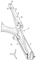
図8には、本発明の第二実施形態に係るスライドドア構造80の断面図が示されており、図9には、図8に示されるスライドドア構造80に設けられたドア高さ調整用ボルト92をその軸方向一方側から見た図が示されている。また、図10には、スライドドア構造80に設けられたリンクアーム機構が斜視図にて示されており、図11、図12(a),(b)には、図10のD−D線断面図、図11のE−E線断面図、図11のF−F線断面図がそれぞれ示されている。また、図13には、スライドドア構造80においてスライドドア12の建て付け調整を行うためにスライドドア12からプロテクションモール54が取り外された状態が示されており、図14には、スライドドア構造80においてスライドドア12の車体に対する建て付け調整をする前の状態を示す説明図、図15には、スライドドア構造80においてスライドドア12の車体に対する建て付け調整をした後の状態を示す説明図がそれぞれ示されている。なお、これらの図において示される矢印Fr、矢印Out、矢印Upは、それぞれ車両前後方向前方側、車両幅方向外側、車両上下方向上側を示している。
FIG. 8 shows a cross-sectional view of the sliding
本発明の第二実施形態に係るスライドドア構造80は、上述の本発明の第一実施形態に係るスライドドア構造10に対し、以下に説明する如く構成を変更したものである。なお、本発明の第二実施形態において、以下に説明する以外の構成については上述の本発明の第一実施形態と同一であるので、この同一の構成については上述の本発明の第一実施形態と同一の符号を用いることとしてその説明を省略する。
The
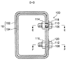
図8に示されるように、本発明の第二実施形態に係るスライドドア構造80では、ドアヒンジ24よりも車両上下方向上側に、スライドドア12の車両上下方向への位置調整を可能とするドア高さ調整機構82が設けられている。このドア高さ調整機構82の構成について詳述すると、インナパネル22には、ドア固定用ボルト46が挿入される固定孔36の車両上下方向上側に貫通孔84が形成されている。また、インナパネル22の車両幅方向外側に設けられたドアインナリインフォースメント38及びドアヒンジリインフォースメント40には、インナパネル22の貫通孔84と整合する位置に貫通孔86,88がそれぞれの板厚方向に貫通形成されている。さらに、ドアヒンジリインフォースメント40の車両外側面には、貫通孔88と同軸的にウェルドナット90が溶接で固着されている。
As shown in FIG. 8, in the sliding
また、このドア高さ調整機構82には、ドア高さ調整手段としてのドア高さ調整用ボルト92が設けられている。ドア高さ調整用ボルト92は、カム部94と、回転軸部としてのネジ部96とを軸方向に一体に備えた構成とされている。カム部94は、図8,図9に示されるように、ネジ部96の中心部から偏芯して設けられている。また、ネジ部96の端面には、所定の工具の係合部と係合される被係合部98が凹設されている。そして、ネジ部96は、車両幅方向内側から上述のインナパネル22に形成された貫通孔84、ドアインナリインフォースメント38及びドアヒンジリインフォースメント40に形成された貫通孔86,88に順次挿入されて、上述のウェルドナット90に螺合されている。また、このようにしてネジ部96がウェルドナット90に螺合された状態では、カム部94がドアヒンジ24に設けられた一対の車両幅方向面24A,24Bのうち車両上下方向上側を向く車両幅方向面24A(ドア高さ方向を向く非当接面)と当接されている。
The door
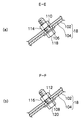
また、図10に示されるように、一対のリンクアーム18のうち、車両前後方向後側に設けられたリンクアーム18は、長手方向の長さを変更するためのリンク長可変構造100を備えた構成とされている。すなわち、このリンクアーム18は、アウタアーム102とインナアーム104とに長手方向に二分割された構成とされている。アウタアーム102は、車両幅方向外側に配置されており、インナアーム104は、車両幅方向内側に配置されている。アウタアーム102及びインナアーム104は、いずれも断面四角状の筒状に構成されており、インナアーム104は、アウタアーム102に対し断面積が小さく構成されてアウタアーム102の内側に挿入されている。
As shown in FIG. 10, of the pair of
また、アウタアーム102には、図10,図11に示されるように、長手方向且つ断面高さ方向(車両上下方向)に離間した二箇所の位置に長孔106,108がそれぞれ板厚方向に貫通形成されている。この長孔106,108は、図12(a),(b)に示されるように、それぞれアウタアーム102の長手方向に長い形状とされている。また、インナアーム104には、各長孔106,108と整合する位置に円孔110,112がそれぞれ板厚方向に貫通形成されており、このインナアーム104の内側には、円孔110,112と同軸的にウェルドナット114,116がそれぞれ溶接で固着されている。
Further, as shown in FIGS. 10 and 11, the
また、このリンク長可変構造100には、リンク長保持手段としてのリンク長保持用ボルト118,120が設けられており、このリンク長保持用ボルト118,120は、アウタアーム102の外側から長孔106,108及び円孔110,112に順次挿入されてウェルドナット114,116とそれぞれ螺合されている。そして、このリンク長可変構造100を備えたリンクアーム18では、リンク長保持用ボルト118,120とウェルドナット114,116とが仮止めの状態とされたときに、長孔106,108内をリンク長保持用ボルト118,120が相対移動する範囲でアウタアーム102とインナアーム104との長手方向における相対位置が変更可能となっている。
The variable
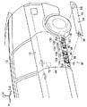
また、図13に示されるように、スライドドア12に設けられたアウタパネル48の下部には、車両前後方向の二箇所の位置に落し込み部122,124がそれぞれ凹設されている。この一対の落し込み部122,124のうち、車両前後方向前側の落し込み部122には、上述のドア固定用ボルト46及びドア高さ調整用ボルト92の車両幅方向外側に位置する部分に、車両側面視にて縦長状の作業孔126(合計2箇所)が板厚方向(車両幅方向)に貫通形成されている。この作業孔126は、車両幅方向外側にドア固定用ボルト46及びドア高さ調整用ボルト92を露出しており、後に詳述するように、車両幅方向外側からドア固定用ボルト46及びウェルドナット32の締結作業並びにウェルドナット90に対するドア高さ調整用ボルト92の回転操作を可能としている。
Further, as shown in FIG. 13, in the lower part of the
また、この落し込み部122の一対の作業孔126の間の位置には、車両側面視にて円形状の作業孔128が板厚方向(車両幅方向)に貫通形成されている。この作業孔128は、車両幅方向外側にドア固定用ボルト46を露出しており、後に詳述するように、車両幅方向外側からドア固定用ボルト46及びウェルドナット32の締結作業を可能としている。
Further, a
また、一対の落し込み部122,124のうち、車両前後方向後側の落し込み部124には、上述のリンク長保持用ボルト118,120の車両幅方向外側に位置する部分に、車両側面視にて横長状の作業孔130(合計2箇所)が板厚方向(車両幅方向)に貫通形成されている。さらに、アウタパネル48の内側のインナパネル22(図8参照)には、上述の横長状の作業孔130と整合する位置に同じく車両側面視にて横長状の作業孔132(合計2箇所)が板厚方向に貫通形成されている。この各作業孔130,132は、車両幅方向外側にリンク長保持用ボルト118,120をそれぞれ露出しており、後に詳述するように、車両幅方向外側からリンク長保持用ボルト118,120及びウェルドナット114,116の締結状態を調整可能としている。
Of the pair of
次に、上記構成からなるスライドドア構造80の作用について説明する。
Next, the operation of the sliding
本発明の第二実施形態に係るスライドドア構造80は、上記各構成により、スライドドア12の車体への建て付け作業(建て付け調整を含む)を、スライドドア12を車体側に閉じた状態で行えるようになっている。以下、これを詳述する。
In the sliding
本発明の第二実施形態に係るスライドドア構造80において、スライドドア12を車体に取り付けるには、先ず、図8に示されるリンクアーム18の車体側をヒンジピン20により車体に回動自在に連結し、リンクアーム18のドア側にドアヒンジ24を設ける。続いて、スライドドア12を車体側に閉じた状態とし、インナパネル22のドアヒンジ取付部34にドアヒンジ24を位置させる。さらに、車両幅方向外側からアウタパネル48の作業孔126,128を介してドア固定用ボルト46をスライドドア12の内部に進入させ、ドアインナリインフォースメント38及びドアヒンジリインフォースメント40の貫通孔42,44を介して、インナパネル22の固定孔36及びドアヒンジ24の貫通孔28にドア固定用ボルト46を挿入する。そして、ドア固定用ボルト46をウェルドナット32に螺合する。なお、このときには、ドア固定用ボルト46とウェルドナット32とを本締めとせずに仮締めとする。
In the sliding
また、このときには、ドア固定用ボルト46が固定孔36及び貫通孔42,44に対し遊挿状態であるので、これにより、ドア固定用ボルト46が固定孔36及び貫通孔42,44内を移動する範囲内でドアヒンジ24に対してスライドドア12が車両上下方向及び車両前後方向に移動自在となる。従って、この段階で、所定の治具を用いてスライドドア12とドアヒンジ24との位置調整、つまり、スライドドア12の車両前後方向及び車両上下方向への位置調整を行う。
At this time, since the
すなわち、スライドドア12の車両前後方向への位置調整は、図14に示されるように、スライドドア12を閉じた状態で、ドア開口13の周縁部とスライドドア12との隙間に治具134を挿入し、ドア開口13の周縁部とスライドドア12との隙間が所定の寸法となるようにスライドドア12を車両前後方向に移動させて行う。
That is, the position of the
また、スライドドア12の車両上下方向への位置調整は、以下の要領で行う。つまり、スライドドア12を閉じた状態で、車両幅方向外側からアウタパネル48の作業孔126を介して所定の工具をスライドドア12の内部に進入させ、この所定の工具の係合部をドア高さ調整用ボルト92の被係合部98に係合させる。そして、この状態で、図15に示されるように、所定の工具を回転させることでドア高さ調整用ボルト92を回転させる。これにより、ドア高さ調整用ボルト92に設けられたカム部94の中心とドアヒンジ24の車両幅方向面24Aとの距離が変更されて、スライドドア12のドアヒンジ24(ひいては車体)に対する車両上下方向の位置が調整される。
Further, the position adjustment of the
また、これらと合わせて、スライドドア12の車両幅方向への位置調整(つまり車両平面視でのスライドドア12の傾き調整)を行う。すなわち、スライドドア12を閉じた状態で、車両幅方向外側からアウタパネル48及びインナパネル22の作業孔130,132を介して所定の工具をスライドドア12の内部に進入させ、この所定の工具でリンク長保持用ボルト118,120を回転させてリンク長保持用ボルト118,120とウェルドナット114,116(図12参照)とを仮止め状態とする。
Together with these, position adjustment of the
このときには、図12(a),(b)に示される長孔106,108内をリンク長保持用ボルト118,120が移動する範囲でアウタアーム102とインナアーム104との長手方向における相対位置、すなわち、リンクアーム18の長手方向の長さを変更することが可能となる。また、リンクアーム18の長手方向の長さが変更可能となることにより、図15に示されるスライドドア12の車両幅方向への位置調整(つまり車両平面視でのスライドドア12の傾き調整)が可能となる。そして、ドア開口13の周縁部とスライドドア12との段差がなくなるように(所定の寸法範囲内に収まるように)スライドドア12の車両幅方向の位置調整(つまり車両平面視でのスライドドア12の傾き調整)を行う。
At this time, the relative position of the
本発明の第二実施形態では、以上の要領で、スライドドア12の建て付け調整として車両上下方向、車両前後方向、車両幅方向への位置調整を行う。そして、スライドドア12の建て付け調整の完了と共に各部を完全な締結状態とする。すなわち、ボルト46とウェルドナット32とを完全な締結状態とすることによりインナパネル22の固定孔36の周縁部とドアヒンジ24とを固定する。また、リンク長保持用ボルト118,120とウェルドナット114,116とを完全な締結状態とすることによりアウタアーム102とリンクアーム104とを固定する。これにより、スライドドア12の車体への建て付け作業を完了する。そして、上述の本発明の第一実施形態と同様に、図13に示されるプロテクションモール54をスライドドア12に車両幅方向内側から一体的に固定する。
In the second embodiment of the present invention, the position adjustment in the vehicle vertical direction, the vehicle front-rear direction, and the vehicle width direction is performed as the installation adjustment of the
以上詳述したように、本発明の第二実施形態に係るスライドドア構造80によれば、スライドドア12の車両幅方向外側からスライドドア12とドアヒンジ24との位置調整及び固定を可能とすることで、スライドドア12の建て付け作業(スライドドア12の建て付け調整を含む)を、スライドドア12を車体側に閉じた状態で行うことが可能である。従って、スライドドア12と車体との位置を直接的に確認しながら、すなわち、建て付け確認しながら、スライドドア12の車体への建て付け調整を行うことができる。これにより、スライドドア12の建て付け調整と建て付け確認との試行錯誤の繰り返しを防止できるので、スライドドア12の車体への建て付け作業性も向上させることができる。
As described above in detail, according to the
特に、本発明の第二実施形態に係るスライドドア構造80によれば、上述の如く、車両幅方向外側からアウタパネル48の作業孔126を介して所定の工具をスライドドア12の内部に進入させ、この所定の工具でドア高さ調整用ボルト92を回転させるだけで、スライドドア12の車両上下方向の位置調整を行うことができる。従って、スライドドア12を車体側に閉じた状態としても、スライドドア12の車両幅方向外側からスライドドア12の車体に対する車両上下方向への建て付け調整を容易に行うことが可能である。
In particular, according to the
また、本発明の第二実施形態に係るスライドドア構造80によれば、ドア高さ調整用ボルト92のカム部94をドアヒンジ24の車両幅方向面24Aに当接するように構成されている。従って、例えばカム部94をドアヒンジ24の板厚部(例えば、固定壁部26)に当接させる構成に比して、カム部24と車両幅方向面24Aとの当接面を車両幅方向に広く取ることができる。これにより、スライドドア12の車両上下方向の位置調整を確実に行うことが可能となる。
Further, according to the
また、本発明の第二実施形態に係るスライドドア構造80によれば、スライドドア12に設けられたドア高さ調整用ボルト92のカム部94がドアヒンジ24の車両上下方向上側を向く車両幅方向面24Aに当接されているので、スライドドア12を車体に閉じた状態で、しかも、スライドドア12の自重がドアヒンジ24に負荷された状態でスライドドア12の車両上下方向の位置調整を行うことができる。これにより、ドア開口13の周縁部とスライドドア12との見切り幅を縮小することが可能となると共に、スライドドア12の建て付け調整と建て付け確認との試行錯誤の繰り返しを防止でき、さらに、スライドドア12の車体に対する車両上下方向への建て付け調整精度をより向上することが可能となる。
Further, according to the
さらに、本発明の第二実施形態に係るスライドドア構造80によれば、車両幅方向外側からアウタパネル48及びインナパネル22の作業孔130,132を介して所定の工具をスライドドア12の内部に進入させ、この所定の工具でリンク長保持用ボルト118,120とウェルドナット114,116(図12参照)とを仮止め状態とすることにより、リンクアーム18の長手方向の長さ、すなわち、スライドドア12の車両幅方向への位置調整(つまり車両平面視でのスライドドア12の傾き調整)が可能となる。従って、スライドドア12を車体側に閉じた状態としても、スライドドア12の車両幅方向外側からスライドドア12の車体に対する車両幅方向への建て付け調整(つまり車両平面視でのスライドドア12の傾き調整)を容易に行うことが可能である。
Furthermore, according to the
また、本発明の第二実施形態に係るスライドドア構造80によれば、リンクアーム18が、アウタアーム102と、アウタアーム102に対し長手方向に相対移動可能なインナアーム104と、を有して構成されており、このアウタアーム102とインナアーム102とがリンク長保持用ボルト118,120によって所望の相対位置に保持されるようになっている。このように、本発明の第二実施形態に係るスライドドア構造80によれば、リンクアーム18の長手方向の長さを簡単な構成により確実に調整することができる。
Further, according to the
また、本発明の第二実施形態に係るスライドドア構造80によれば、リンクアーム18が、アウタアーム102の内側にインナアーム104が挿入された構成とされている。従って、リンクアーム18がいわゆる二重構造となるので、リンクアーム18の剛性を高めることができる。これにより、例えば、スライドドア12に作用した側突荷重の車体への荷重伝達効率やスライドドア12の支持剛性を高めることができる。
Further, according to the
10,80 スライドドア構造
12 スライドドア
13 ドア開口
18 リンクアーム
22 インナパネル
24 ドアヒンジ
24A 車両幅方向面(非当接面)
34 ドアヒンジ取付部
36 固定孔
46 ドア固定用ボルト(固定手段、固定具)
48 アウタパネル
50 作業孔
54 プロテクションモール(隠蔽手段)
92 ドア高さ調整用ボルト(固定手段、ドア高さ調整手段)
94 カム部
96 ネジ部(回転軸部)
118,120 リンク長保持用ボルト(リンク長保持手段)
102 アウタアーム
104 インナアーム
DESCRIPTION OF
34 Door
48
92 Door height adjustment bolt (fixing means, door height adjustment means)
94
118, 120 Link length holding bolt (link length holding means)
102
Claims (9)
前記リンクアームの他端側がドアヒンジを介して回動自在に取り付けられ、前記リンクアームの揺動によって前記車体に設けられたドア開口を開閉するスライドドアと、
前記スライドドアと前記車体との位置調整及び固定を前記スライドドアのドア厚さ方向外側から可能とする固定手段と、
を備えることを特徴とするスライドドア構造。 A link arm whose one end is rotatably connected to the vehicle body;
A slide door that is pivotably attached to the other end of the link arm via a door hinge, and that opens and closes a door opening provided in the vehicle body by swinging the link arm;
Fixing means that enables position adjustment and fixing of the sliding door and the vehicle body from the outside in the thickness direction of the sliding door;
A sliding door structure characterized by comprising:
前記リンクアームの他端側がドアヒンジを介して回動自在に取り付けられ、前記リンクアームの揺動によって前記車体に設けられたドア開口を開閉するスライドドアと、
前記スライドドアと前記ドアヒンジとの位置調整及び固定を前記スライドドアのドア厚さ方向外側から可能とする固定手段と、
を備えることを特徴とするスライドドア構造。 A link arm whose one end is rotatably connected to the vehicle body;
A slide door that is pivotably attached to the other end of the link arm via a door hinge, and that opens and closes a door opening provided in the vehicle body by swinging the link arm;
Fixing means for enabling position adjustment and fixing of the sliding door and the door hinge from the door thickness direction outside of the sliding door;
A sliding door structure characterized by comprising:
ドア厚さ方向内側に前記ドアヒンジが取り付けられるインナパネルと、
前記インナパネルのドア厚さ方向外側に設けられたアウタパネルと、
を備え、
前記固定手段は、前記インナパネルの前記ドアヒンジの取付部に板厚方向に貫通形成された固定孔に遊挿されると共に前記インナパネルの前記固定孔の周縁部と前記ドアヒンジとを固定し且つ前記アウタパネルに板厚方向に貫通形成された作業孔によってドア厚さ方向外側に露出された固定具を有して構成されていることを特徴とする請求項1又は請求項2に記載のスライドドア構造。 The sliding door is
An inner panel to which the door hinge is attached on the inside in the door thickness direction;
An outer panel provided on the outside in the door thickness direction of the inner panel;
With
The fixing means is loosely inserted into a fixing hole formed in a plate thickness direction so as to penetrate the attachment portion of the door hinge of the inner panel, and fixes a peripheral portion of the fixing hole of the inner panel and the door hinge, and the outer panel. The sliding door structure according to claim 1, further comprising a fixing tool that is exposed to the outside in the thickness direction of the door through a work hole that is formed so as to penetrate in the thickness direction of the door.
前記固定手段には、前記被当接面と当接するカム部及び前記カム部と一体に形成された回転軸部を有し、前記回転軸部が前記スライドドアに回転操作可能に設けられると共に前記スライドドアのドア厚さ方向外側に露出されて構成されたドア高さ調整手段が備えられていることを特徴とする請求項1乃至請求項4のいずれか一項に記載のスライドドア構造。 The door hinge is provided with a contact surface facing the door height direction of the slide door,
The fixing means includes a cam portion that contacts the abutted surface and a rotating shaft portion formed integrally with the cam portion, and the rotating shaft portion is provided on the slide door so as to be rotatable and The slide door structure according to any one of claims 1 to 4, further comprising door height adjusting means that is configured to be exposed outside the door in the thickness direction of the slide door.
前記リンク長保持手段は、前記スライドドアのドア厚さ方向外側に露出されていることを特徴とする請求項1乃至請求項5のいずれか一項に記載のスライドドア構造。 The link arm is configured to be capable of changing the length in the longitudinal direction, and has link length holding means for holding the link arm at a desired length in the longitudinal direction,
The slide door structure according to any one of claims 1 to 5, wherein the link length holding means is exposed to the outside in the door thickness direction of the slide door.
アウタアームと、
前記アウタアームに対し長手方向に相対移動可能なインナアームと、
を有して構成され、
前記リンク長保持手段は、前記アウタアームと前記インナアームとを所望の相対位置に保持可能に構成されていることを特徴とする請求項6に記載のスライドドア構造。 The link arm is
Outer arm,
An inner arm movable relative to the outer arm in the longitudinal direction;
Comprising
The sliding door structure according to claim 6, wherein the link length holding means is configured to hold the outer arm and the inner arm at a desired relative position.
Priority Applications (1)
| Application Number | Priority Date | Filing Date | Title |
|---|---|---|---|
| JP2006315128A JP2007192015A (en) | 2005-12-19 | 2006-11-22 | Sliding door structure |
Applications Claiming Priority (2)
| Application Number | Priority Date | Filing Date | Title |
|---|---|---|---|
| JP2005364991 | 2005-12-19 | ||
| JP2006315128A JP2007192015A (en) | 2005-12-19 | 2006-11-22 | Sliding door structure |
Publications (1)
| Publication Number | Publication Date |
|---|---|
| JP2007192015A true JP2007192015A (en) | 2007-08-02 |
Family
ID=38447924
Family Applications (1)
| Application Number | Title | Priority Date | Filing Date |
|---|---|---|---|
| JP2006315128A Pending JP2007192015A (en) | 2005-12-19 | 2006-11-22 | Sliding door structure |
Country Status (1)
| Country | Link |
|---|---|
| JP (1) | JP2007192015A (en) |
Cited By (3)
| Publication number | Priority date | Publication date | Assignee | Title |
|---|---|---|---|---|
| JP2018016266A (en) * | 2016-07-29 | 2018-02-01 | トヨタ自動車株式会社 | Vehicle side part structure |
| WO2020122844A1 (en) * | 2018-12-14 | 2020-06-18 | Rollmech Automotive Sanayi Ve Ticaret Anonim Sirketi | A sliding door mechanism with height adjustability |
| EP4198231A1 (en) * | 2021-12-15 | 2023-06-21 | Ningbo Geely Automobile Research & Development Co. Ltd. | A door tilting system and a method for adjusting a door tilting system |
-
2006
- 2006-11-22 JP JP2006315128A patent/JP2007192015A/en active Pending
Cited By (5)
| Publication number | Priority date | Publication date | Assignee | Title |
|---|---|---|---|---|
| JP2018016266A (en) * | 2016-07-29 | 2018-02-01 | トヨタ自動車株式会社 | Vehicle side part structure |
| US10040339B2 (en) | 2016-07-29 | 2018-08-07 | Toyota Jidosha Kabushiki Kaisha | Vehicle side portion structure |
| WO2020122844A1 (en) * | 2018-12-14 | 2020-06-18 | Rollmech Automotive Sanayi Ve Ticaret Anonim Sirketi | A sliding door mechanism with height adjustability |
| EP4198231A1 (en) * | 2021-12-15 | 2023-06-21 | Ningbo Geely Automobile Research & Development Co. Ltd. | A door tilting system and a method for adjusting a door tilting system |
| WO2023109684A1 (en) * | 2021-12-15 | 2023-06-22 | Ningbo Geely Automobile Research & Development Co., Ltd. | A door tilting system and a method for adjusting a door tilting system |
Similar Documents
| Publication | Publication Date | Title |
|---|---|---|
| US6808225B2 (en) | Double door construction for vehicle | |
| CN103597158B (en) | Locking device used for vehicle | |
| EP2540936B1 (en) | Retaining device for vehicle door | |
| KR101252019B1 (en) | Cab for construction machine | |
| JP5056389B2 (en) | Restraint structure for sliding door for vehicles | |
| CN110017074B (en) | Hinge mechanism | |
| US9963924B2 (en) | Door support structure of automotive vehicle | |
| JP5165439B2 (en) | Vehicle door outer handle structure | |
| JP4534662B2 (en) | Vehicle door handle | |
| JP2009243102A (en) | Outer handle structure of door of vehicle | |
| JP2007192015A (en) | Sliding door structure | |
| JP4717015B2 (en) | Door locking device | |
| JP2011102485A (en) | Door lock structure | |
| JP5022175B2 (en) | Mounting structure of latch mechanism for fully opening holding in sliding door for vehicle | |
| JP2015199425A (en) | Door lock structure of center pillar-less vehicle | |
| JP2009297658A (en) | Door fixing jig | |
| JPH10147166A (en) | Seat mounting structure | |
| JP5857679B2 (en) | Trunk lid mounting vehicle structure | |
| US20190193532A1 (en) | Vehicle door structure | |
| JP4899432B2 (en) | Vehicle hood hinge structure | |
| JP6356719B2 (en) | Automatic switchgear for vehicles | |
| KR101947046B1 (en) | Mounting structure of retractable outside door handle assembly for vehicle | |
| JP4421560B2 (en) | Automobile door installation jig | |
| JP5172601B2 (en) | Opening / closing body operating handle mounting structure | |
| JP4382179B2 (en) | Automotive door handle structure |