JP2007191203A - Covering method for roll bearing - Google Patents
Covering method for roll bearing Download PDFInfo
- Publication number
- JP2007191203A JP2007191203A JP2006012532A JP2006012532A JP2007191203A JP 2007191203 A JP2007191203 A JP 2007191203A JP 2006012532 A JP2006012532 A JP 2006012532A JP 2006012532 A JP2006012532 A JP 2006012532A JP 2007191203 A JP2007191203 A JP 2007191203A
- Authority
- JP
- Japan
- Prior art keywords
- bearing
- film
- outer ring
- inner ring
- rolling
- Prior art date
- Legal status (The legal status is an assumption and is not a legal conclusion. Google has not performed a legal analysis and makes no representation as to the accuracy of the status listed.)
- Withdrawn
Links
Images


Abstract
Description
本発明は、転がり軸受をフィルムにより被覆する方法に係り、特に、軸受取付時における作業効率を向上するのに好適な転がり軸受の被覆方法に関する。 The present invention relates to a method of coating a rolling bearing with a film, and more particularly to a method of coating a rolling bearing suitable for improving work efficiency when the bearing is mounted.
アンギュラ玉軸受や円筒ころ軸受等の転がり軸受を工作機械用スピンドルに組み込む場合、軸受の剛性および最高回転数に適した内部荷重を適切にするために、軸およびハウジングと軸受の嵌合を調整する必要がある。そのため、軸受の取付現場では、軸受の取付作業にあたって、軸受の主要3寸法(内径、外径、幅)を把握しなければならない。
軸受メーカでは、こうした需要に応じて、軸受の寸法を測定し、測定した寸法を記述した検査成績証という書面を軸受に添付して顧客に提供している。
When rolling bearings such as angular ball bearings and cylindrical roller bearings are incorporated into a spindle for machine tools, the fitting of the shaft and housing to the bearing is adjusted in order to make the internal load suitable for the rigidity and maximum rotation speed of the bearing. There is a need. Therefore, at the installation site of the bearing, it is necessary to grasp the three main dimensions (inner diameter, outer diameter, and width) of the bearing when the bearing is installed.
In response to such demands, bearing manufacturers measure the dimensions of the bearings and provide the customer with a written report of inspection results describing the measured dimensions.
特許文献1記載の発明は、機械要素の寸法および諸元を保持する諸元データベース(以下、データベースのことを単にDBと略記する。)を備え、選定すべき機械要素の仕様および使用条件情報、購入条件、選定候補に関する情報の出力態様を示す情報を含む機械要素選定情報を受信し、仕様および使用条件と諸元DBの情報に基づいて選定候補を抽出し、抽出した選定候補のうち購入条件を満たす選定候補に関する情報を、出力態様にしたがって出力するものである。
しかしながら、上記軸受メーカによる提供方法にあっては、寸法情報を検査成績証により提供するため、軸受の取付現場では、軸受を取り付ける際に所定の保管場所から検査成績証を探して持ってこなければならず、寸法確認作業に手間を要していた。また、特許文献1記載の発明にあっては、軸受出荷前に軸受を選定するために寸法情報を提示するものであり、軸受出荷後は、寸法情報が検査成績証により提供されるので上記同様の問題が発生する。
この問題を解決するため、主要3寸法その他の諸元を示す諸元情報をバーコードとして軸受の表面に刻印する方法が考えられる。これにより、作業時にバーコードを読み取れば、諸元情報をその場で得ることができ、作業効率が向上する。
However, in the above-mentioned method provided by the bearing manufacturer, the dimensional information is provided by the inspection certificate, so at the installation site of the bearing, when the bearing is installed, the inspection certificate must be searched from the specified storage location and brought. In other words, it took time and labor to confirm the dimensions. Further, in the invention described in
In order to solve this problem, a method is conceivable in which specification information indicating the three main dimensions and other specifications is stamped on the surface of the bearing as a bar code. Thereby, if the barcode is read at the time of work, the specification information can be obtained on the spot, and the work efficiency is improved.
一方、転がり軸受は、軸受内部を含む全面に防錆油を付着させ、フィルムに封入し、フィルム内を減圧して封止した状態で出荷される。このように減圧形態で出荷されるため、フィルムの真空引き時にフィルムにしわが発生する。そのため、軸受の表面にバーコードを刻印した場合、フィルムにより被覆された状態では、しわの影響によりバーコードが読み取れない可能性がある。この場合は、フィルムを一旦開封してからバーコードを読み取らなくてはならない。寸法によっては使用しない場合もあり、そのような場合まで開封しては作業効率が良くない。
そこで、本発明は、このような従来の技術の有する未解決の課題に着目してなされたものであって、軸受取付時における作業効率を向上するのに好適な転がり軸受の被覆方法を提供することを目的としている。
On the other hand, rolling bearings are shipped in a state in which rust preventive oil is attached to the entire surface including the inside of the bearing, sealed in a film, and the inside of the film is depressurized and sealed. Thus, since it is shipped in a reduced pressure form, the film is wrinkled when the film is evacuated. Therefore, when a bar code is engraved on the surface of the bearing, the bar code may not be read due to the effect of wrinkles when it is covered with a film. In this case, the bar code must be read after opening the film. Depending on the dimensions, it may not be used, and it is not efficient to open until such a case.
Therefore, the present invention has been made paying attention to such an unsolved problem of the conventional technology, and provides a rolling bearing coating method suitable for improving the working efficiency at the time of mounting the bearing. The purpose is that.
上記目的を達成するために、本発明に係る請求項1記載の転がり軸受の被覆方法は、内輪と、外輪と、前記内輪および前記外輪との間に転動自在に配設された複数の転動体とを備えた転がり軸受をフィルムにより被覆する方法であって、前記軸受の諸元に関する諸元情報を識別マークとして前記軸受の表面に刻印する刻印工程と、2つのフィルム間または袋状のフィルム内に前記軸受を配置し、前記フィルム面のうち前記識別マークの刻印面に位置する部分を当該刻印面に押し当てながら前記フィルム内を減圧する減圧工程と、前記フィルムの開口部を閉鎖する閉鎖工程とを含む。
これにより、フィルム面のうち識別マークの刻印面に位置する部分を刻印面に押し当てながら減圧するため、識別マークの刻印面付近にしわが発生するのを抑制することができる。そのため、フィルムに被覆された状態でも識別マークを読み取ることができる。
In order to achieve the above object, a rolling bearing covering method according to
Thereby, since it decompresses, pressing the part located in the marking surface of an identification mark among film surfaces, it can suppress that a wrinkle generate | occur | produces near the marking surface of an identification mark. Therefore, the identification mark can be read even when the film is covered.
さらに、本発明に係る請求項2記載の転がり軸受の被覆方法は、内輪と、外輪と、前記内輪および前記外輪との間に転動自在に配設された複数の転動体とを備えた転がり軸受をフィルムにより被覆する方法であって、前記軸受の諸元に関する諸元情報を識別マークとして前記軸受の表面に刻印する刻印工程と、2つのフィルム間または袋状のフィルム内に前記軸受を配置し、前記軸受の上面および下面の一方の面に接する前記フィルム面のうち前記内輪の内側空隙部に位置する部分を前記上面および下面の他方の面に向かって押圧しながら前記フィルム内を減圧する減圧工程と、前記フィルムの開口部を閉鎖する閉鎖工程とを含む。
Furthermore, the rolling bearing covering method according to
これにより、軸受の上面および下面の一方の面に接するフィルム面のうち内輪の内側空隙部に位置する部分を上面および下面の他方の面に向かって押圧しながら減圧するため、識別マークの刻印面を含む軸受の表面にしわが発生するのを抑制することができる。そのため、フィルムに被覆された状態でも識別マークを読み取ることができる。 As a result, the portion of the film surface that is in contact with one of the upper and lower surfaces of the bearing is decompressed while pressing the portion located in the inner space of the inner ring toward the other surface of the upper and lower surfaces. The generation of wrinkles on the surface of the bearing including Therefore, the identification mark can be read even when the film is covered.
さらに、本発明に係る請求項3記載の転がり軸受の被覆方法は、内輪と、外輪と、前記内輪および前記外輪との間に転動自在に配設された複数の転動体とを備えた転がり軸受をフィルムにより被覆する方法であって、前記軸受の諸元に関する諸元情報を識別マークとして前記軸受の表面に刻印する刻印工程と、2つのフィルム間または袋状のフィルム内に前記軸受を配置し、前記軸受を挟んで前記フィルムの両端に張力を加えながら前記フィルム内を減圧する減圧工程と、前記フィルムの開口部を閉鎖する閉鎖工程とを含む。
これにより、軸受を挟んでフィルムの両端に張力を加えながら減圧するため、識別マークの刻印面を含む軸受の表面にしわが発生するのを抑制することができる。そのため、フィルムに被覆された状態でも識別マークを読み取ることができる。
Furthermore, the rolling bearing covering method according to
As a result, the pressure is reduced while applying tension to both ends of the film across the bearing, so that the occurrence of wrinkles on the surface of the bearing including the marking surface of the identification mark can be suppressed. Therefore, the identification mark can be read even when the film is covered.
さらに、本発明に係る請求項4記載の転がり軸受の被覆方法は、請求項1ないし3のいずれか1項に記載の転がり軸受の被覆方法において、前記刻印工程は、前記識別マークを前記外輪の側面に刻印する。
これにより、識別マークが外輪の側面に刻印されているため、軸受取付時にハウジング等と重なり合って隠蔽されることなく、読み取りやすい。
さらに、本発明に係る請求項5記載の転がり軸受の被覆方法は、請求項1ないし4のいずれか1項に記載の転がり軸受の被覆方法において、前記閉鎖工程は、前記フィルムの開口部を熱により接着する。
Furthermore, the rolling bearing coating method according to
Thereby, since the identification mark is engraved on the side surface of the outer ring, it is easy to read without being overlapped with the housing or the like when the bearing is mounted.
Furthermore, the rolling bearing coating method according to
以上説明したように、本発明に係る請求項1ないし5記載の転がり軸受の被覆方法によれば、フィルムに被覆された状態でも識別マークを読み取ることができるので、軸受取付作業にあたってフィルムを開封しなくてすむ。また、識別マークを読み取らせるだけでその諸元情報が得られる。したがって、従来に比して、軸受取付時における作業効率を向上することができるという効果が得られる。 As described above, according to the rolling bearing coating method of the first to fifth aspects of the present invention, the identification mark can be read even when the film is covered with the film. No need. Further, the specification information can be obtained simply by reading the identification mark. Therefore, the effect that the working efficiency at the time of mounting a bearing can be improved as compared with the prior art.
以下、本発明の第1の実施の形態を図面を参照しながら説明する。図1ないし図4は、本発明に係る転がり軸受の被覆方法の第1の実施の形態を示す図である。
まず、本発明を適用するアンギュラ玉軸受10の構成を説明する。
図1は、アンギュラ玉軸受10の断面図である。
アンギュラ玉軸受10は、図1に示すように、内輪1と、外輪2と、内輪1および外輪2の間で転動自在に配設された複数の玉(転動体3)と、保持器4とからなる。
また、アンギュラ玉軸受10は、軸受全面に、ペントロタムを含有しない防錆油が、40μm以下の油膜厚さで付着されている(図示せず)。さらに、内輪1および外輪2の間に形成され玉3が配設された空隙部内には、グリース5が封入されている。
Hereinafter, a first embodiment of the present invention will be described with reference to the drawings. 1 to 4 are views showing a first embodiment of a rolling bearing covering method according to the present invention.
First, the structure of the angular ball bearing 10 to which the present invention is applied will be described.
FIG. 1 is a cross-sectional view of an angular ball bearing 10.
As shown in FIG. 1, the angular ball bearing 10 includes an
Further, the angular ball bearing 10 has a rust preventive oil containing no pentrotum attached to the entire bearing surface with an oil film thickness of 40 μm or less (not shown). Furthermore,
図2は、アンギュラ玉軸受10の上面図である。
外輪2の側面には、図2に示すように、2次元バーコード(例えば、QRコード)8が刻印されている。2次元バーコード8には、管理番号、軸受の種別ごとに割り当てられる呼び番号、主要3寸法、玉径、球数およびPDCを示す寸法情報、グリースの銘柄および封入量を示すグリース情報、回転精度並びに製造ロット番号が含まれている。管理番号は、軸受ごとに割り当てられる製品シリアル番号、および製品シリアル番号から所定の演算式により求められる照合番号から構成される。照合番号は、情報の真偽を判定するために用いられる。
FIG. 2 is a top view of the angular ball bearing 10.
As shown in FIG. 2, a two-dimensional bar code (for example, QR code) 8 is engraved on the side surface of the
図3は、アンギュラ玉軸受10の斜視図である。
アンギュラ玉軸受10は、図3に示すように、気化性防錆フィルム(アイセロ化学社製,ボーセロン)6からなる袋内に包装されて、袋内部が減圧状態に保持されている。フィルム6の周縁7は熱圧着されている。熱圧着とは、両方または一方の材料に熱により可塑性を生じさせて圧力をかけて接合することをいう。
FIG. 3 is a perspective view of the angular ball bearing 10.
As shown in FIG. 3, the angular ball bearing 10 is packaged in a bag made of a vaporizable rust-proof film (manufactured by Aicello Chemical Co., Ltd., Bocellon) 6, and the inside of the bag is held in a reduced pressure state. The
次に、アンギュラ玉軸受10の被覆方法を説明する。
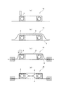
図4は、アンギュラ玉軸受10の被覆方法を示す図である。
まず、図4(a)に示すように、レーザにより外輪2の側面に2次元バーコード8を刻印する。次いで、図4(b)に示すように、アンギュラ玉軸受10の下面に第1のフィルム6を敷き、アンギュラ玉軸受10の上面に第2のフィルム6を被せ、2枚のフィルム6の間にアンギュラ玉軸受10を配置する。次いで、図4(c)に示すように、2枚のフィルム6の周縁7を固定するとともに、第2のフィルム面のうち2次元バーコード8の刻印面に位置する部分を刻印面に押し当てながらフィルム内を減圧する。そして、図4(d)に示すように、2枚のフィルム6の全周をむら無く熱圧着する。
Next, a method for covering the angular ball bearing 10 will be described.
FIG. 4 is a diagram illustrating a method of covering the angular ball bearing 10.
First, as shown in FIG. 4A, a two-
このようにして、本実施の形態では、アンギュラ玉軸受10の諸元に関する諸元情報を2次元バーコード8としてアンギュラ玉軸受10の表面に刻印し、2つのフィルム6の間にアンギュラ玉軸受10を配置し、フィルム面のうち2次元バーコード8の刻印面に位置する部分を刻印面に押し当てながらフィルム内を減圧し、フィルム6の全周を熱圧着した。
In this way, in the present embodiment, the specification information regarding the specifications of the
これにより、2次元バーコード8の刻印面にしわが発生するのを抑制することができる。そのため、フィルム6に被覆された状態でも2次元バーコード8を読み取ることができるので、軸受取付作業にあたってフィルム6を開封しなくてすむ。また、2次元バーコード8を読み取らせるだけでその諸元情報が得られる。したがって、従来に比して、軸受取付時における作業効率を向上することができる。
さらに、本実施の形態では、2次元バーコード8を外輪2の側面に刻印した。
これにより、2次元バーコード8が軸受取付時にハウジング等と重なり合って隠蔽されることなく、読み取りやすい。
Thereby, wrinkles can be prevented from occurring on the marking surface of the two-
Further, in the present embodiment, the two-
Thereby, the two-
次に、本発明の第2の実施の形態を図面を参照しながら説明する。
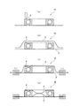
図5は、第2の実施の形態に係るアンギュラ玉軸受10の被覆方法を示す図である。
まず、図5(a)に示すように、レーザにより外輪2の側面に2次元バーコード8を刻印する。次いで、図5(b)に示すように、アンギュラ玉軸受10の下面に第1のフィルム6を敷き、アンギュラ玉軸受10の上面に第2のフィルム6を被せ、2枚のフィルム6の間にアンギュラ玉軸受10を配置する。次いで、図5(c)に示すように、2枚のフィルム6の周縁7を固定するとともに、第2のフィルム面のうち内輪1の内側空隙部に位置する部分を下面に向かって押圧しながらフィルム内を減圧する。そして、図5(d)に示すように、2枚のフィルム6の全周をむら無く熱圧着する。
このような方法であっても、第1の実施の形態と同様に、アンギュラ玉軸受10の表面にしわが発生するのを抑制することができるので、フィルム6に被覆された状態でも2次元バーコード8を読み取ることができる。
Next, a second embodiment of the present invention will be described with reference to the drawings.
FIG. 5 is a diagram illustrating a method of covering the
First, as shown in FIG. 5A, a two-
Even in such a method, as in the first embodiment, it is possible to suppress the occurrence of wrinkles on the surface of the
次に、本発明の第3の実施の形態を図面を参照しながら説明する。
図6は、第3の実施の形態に係るアンギュラ玉軸受10の被覆方法を示す図である。
まず、図6(a)に示すように、レーザにより外輪2の側面に2次元バーコード8を刻印する。次いで、図6(b)に示すように、アンギュラ玉軸受10の下面に第1のフィルム6を敷き、アンギュラ玉軸受10の上面に第2のフィルム6を被せ、2枚のフィルム6の間にアンギュラ玉軸受10を配置する。次いで、図6(c)に示すように、2枚のフィルム6の周縁7を固定するとともに、フィルム6の周縁7を外側に引っ張りながらフィルム内を減圧する。そして、図6(d)に示すように、2枚のフィルム6の全周をむら無く熱圧着する。
Next, a third embodiment of the present invention will be described with reference to the drawings.
FIG. 6 is a diagram illustrating a method of covering the
First, as shown in FIG. 6A, a two-
このような方法であっても、第1の実施の形態と同様に、アンギュラ玉軸受10の表面にしわが発生するのを抑制することができるので、フィルム6に被覆された状態でも2次元バーコード8を読み取ることができる。
なお、上記第1ないし第3の実施の形態においては、2枚のフィルム6によりアンギュラ玉軸受10を被覆したが、これに限らず、袋状のフィルムにアンギュラ玉軸受10を封入してもよい。この場合、上記第1ないし第3の実施の形態と同様にフィルムのポケットを熱圧着すればよい。
また、上記第1ないし第3の実施の形態においては、アンギュラ玉軸受10を適用したが、これに限定するものではなく、深溝玉軸受、円筒ころ軸受、円錐ころ軸受などを適用してもよい。
Even in such a method, as in the first embodiment, it is possible to suppress the occurrence of wrinkles on the surface of the
In the first to third embodiments, the
In the first to third embodiments, the
1 内輪
2 外輪
3 玉(転動体)
4 保持器
5 グリース
6 気化性防錆フィルム
8 2次元バーコード
10 アンギュラ玉軸受
1
4
Claims (5)
前記軸受の諸元に関する諸元情報を識別マークとして前記軸受の表面に刻印する刻印工程と、2つのフィルム間または袋状のフィルム内に前記軸受を配置し、前記フィルム面のうち前記識別マークの刻印面に位置する部分を当該刻印面に押し当てながら前記フィルム内を減圧する減圧工程と、前記フィルムの開口部を閉鎖する閉鎖工程とを含むことを特徴とする転がり軸受の被覆方法。 A method of covering a rolling bearing provided with an inner ring, an outer ring, and a plurality of rolling elements arranged between the inner ring and the outer ring so as to be freely rollable with a film,
An engraving process for imprinting on the surface of the bearing as the identification information with respect to the specification information of the bearing, the bearing is disposed between two films or in a bag-like film, and the identification mark of the film surface A rolling bearing coating method comprising: a pressure reducing step for reducing the pressure inside the film while pressing a portion located on the marking surface against the marking surface; and a closing step for closing an opening of the film.
前記軸受の諸元に関する諸元情報を識別マークとして前記軸受の表面に刻印する刻印工程と、2つのフィルム間または袋状のフィルム内に前記軸受を配置し、前記軸受の上面および下面の一方の面に接する前記フィルム面のうち前記内輪の内側空隙部に位置する部分を前記上面および下面の他方の面に向かって押圧しながら前記フィルム内を減圧する減圧工程と、前記フィルムの開口部を閉鎖する閉鎖工程とを含むことを特徴とする転がり軸受の被覆方法。 A method of covering a rolling bearing provided with an inner ring, an outer ring, and a plurality of rolling elements arranged between the inner ring and the outer ring so as to be freely rollable with a film,
An engraving step for imprinting on the surface of the bearing with the specification information on the specifications of the bearing as an identification mark, the bearing is disposed between two films or in a bag-like film, and one of the upper and lower surfaces of the bearing Depressurizing step of depressurizing the film while pressing a portion of the film surface in contact with the surface located in the inner space of the inner ring toward the other surface of the upper surface and the lower surface, and closing the opening of the film A rolling bearing covering method, comprising: a closing step.
前記軸受の諸元に関する諸元情報を識別マークとして前記軸受の表面に刻印する刻印工程と、2つのフィルム間または袋状のフィルム内に前記軸受を配置し、前記軸受を挟んで前記フィルムの両端に張力を加えながら前記フィルム内を減圧する減圧工程と、前記フィルムの開口部を閉鎖する閉鎖工程とを含むことを特徴とする転がり軸受の被覆方法。 A method of covering a rolling bearing provided with an inner ring, an outer ring, and a plurality of rolling elements arranged between the inner ring and the outer ring so as to be freely rollable with a film,
An engraving process for imprinting on the surface of the bearing with the specification information on the specifications of the bearing as an identification mark, the bearing is disposed between two films or in a bag-like film, and both ends of the film sandwiching the bearing A rolling bearing coating method comprising: a pressure reducing step for reducing the pressure inside the film while applying tension to the film; and a closing step for closing the opening of the film.
前記刻印工程は、前記識別マークを前記外輪の側面に刻印することを特徴とする転がり軸受の被覆方法。 In any one of Claims 1 thru | or 3,
The method for coating a rolling bearing, wherein in the marking step, the identification mark is stamped on a side surface of the outer ring.
前記閉鎖工程は、前記フィルムの開口部を熱により接着することを特徴とする転がり軸受の被覆方法。 In any one of Claims 1 thru | or 4,
In the closing step, the opening of the film is bonded by heat.
Priority Applications (1)
| Application Number | Priority Date | Filing Date | Title |
|---|---|---|---|
| JP2006012532A JP2007191203A (en) | 2006-01-20 | 2006-01-20 | Covering method for roll bearing |
Applications Claiming Priority (1)
| Application Number | Priority Date | Filing Date | Title |
|---|---|---|---|
| JP2006012532A JP2007191203A (en) | 2006-01-20 | 2006-01-20 | Covering method for roll bearing |
Publications (1)
| Publication Number | Publication Date |
|---|---|
| JP2007191203A true JP2007191203A (en) | 2007-08-02 |
Family
ID=38447212
Family Applications (1)
| Application Number | Title | Priority Date | Filing Date |
|---|---|---|---|
| JP2006012532A Withdrawn JP2007191203A (en) | 2006-01-20 | 2006-01-20 | Covering method for roll bearing |
Country Status (1)
| Country | Link |
|---|---|
| JP (1) | JP2007191203A (en) |
Cited By (7)
| Publication number | Priority date | Publication date | Assignee | Title |
|---|---|---|---|---|
| WO2011064061A1 (en) * | 2009-11-30 | 2011-06-03 | Schaeffler Technologies Gmbh & Co. Kg | Electrically and/or thermally insulated anti-friction bearing |
| WO2014192177A1 (en) * | 2013-05-31 | 2014-12-04 | 日本精工株式会社 | Rolling bearing and method for wrapping same |
| JP2015064092A (en) * | 2013-09-26 | 2015-04-09 | 株式会社ジェイテクト | Bearing, method of manufacturing bearing, and method of managing bearing |
| JP2015064091A (en) * | 2013-09-26 | 2015-04-09 | 株式会社ジェイテクト | Bearing, method of managing bearing, and method of manufacturing bearing |
| WO2015069169A1 (en) * | 2013-11-06 | 2015-05-14 | Aktiebolaget Skf | Packaging device for rolling element bearings, use of a packaging device, and method for manufacturing the packaging device |
| DE102015209272A1 (en) * | 2015-05-21 | 2016-11-24 | Aktiebolaget Skf | Method for maintenance and / or repair of a machine installation and for transporting a bearing arrangement |
| CN111322318A (en) * | 2018-12-17 | 2020-06-23 | 斯凯孚公司 | System with rolling bearing |
-
2006
- 2006-01-20 JP JP2006012532A patent/JP2007191203A/en not_active Withdrawn
Cited By (16)
| Publication number | Priority date | Publication date | Assignee | Title |
|---|---|---|---|---|
| WO2011064061A1 (en) * | 2009-11-30 | 2011-06-03 | Schaeffler Technologies Gmbh & Co. Kg | Electrically and/or thermally insulated anti-friction bearing |
| CN102639887A (en) * | 2009-11-30 | 2012-08-15 | 谢夫勒科技股份两合公司 | Electrically and/or thermally insulated anti-friction bearing |
| US8764301B2 (en) | 2009-11-30 | 2014-07-01 | Schaeffler Technologies AG & Co. KG | Thermally insulated anti-friction bearing |
| JPWO2014192177A1 (en) * | 2013-05-31 | 2017-02-23 | 日本精工株式会社 | Rolling bearing and packaging method thereof |
| CN104411989A (en) * | 2013-05-31 | 2015-03-11 | 日本精工株式会社 | Rolling bearing and method for wrapping same |
| US9377057B2 (en) | 2013-05-31 | 2016-06-28 | Nsk Ltd. | Rolling bearing and its packaging method |
| US9523391B2 (en) | 2013-05-31 | 2016-12-20 | Nsk Ltd. | Rolling bearing and its packaging method |
| WO2014192177A1 (en) * | 2013-05-31 | 2014-12-04 | 日本精工株式会社 | Rolling bearing and method for wrapping same |
| USRE48321E1 (en) | 2013-05-31 | 2020-11-24 | Nsk Ltd. | Rolling bearing and its packaging method |
| USRE48337E1 (en) | 2013-05-31 | 2020-12-01 | Nsk Ltd. | Rolling bearing and its packaging method |
| JP2015064092A (en) * | 2013-09-26 | 2015-04-09 | 株式会社ジェイテクト | Bearing, method of manufacturing bearing, and method of managing bearing |
| JP2015064091A (en) * | 2013-09-26 | 2015-04-09 | 株式会社ジェイテクト | Bearing, method of managing bearing, and method of manufacturing bearing |
| WO2015069169A1 (en) * | 2013-11-06 | 2015-05-14 | Aktiebolaget Skf | Packaging device for rolling element bearings, use of a packaging device, and method for manufacturing the packaging device |
| CN105658542A (en) * | 2013-11-06 | 2016-06-08 | 斯凯孚公司 | Packaging device for rolling element bearings |
| DE102015209272A1 (en) * | 2015-05-21 | 2016-11-24 | Aktiebolaget Skf | Method for maintenance and / or repair of a machine installation and for transporting a bearing arrangement |
| CN111322318A (en) * | 2018-12-17 | 2020-06-23 | 斯凯孚公司 | System with rolling bearing |
Similar Documents
| Publication | Publication Date | Title |
|---|---|---|
| JP2007191203A (en) | Covering method for roll bearing | |
| US7896553B2 (en) | Bearing device for wheel | |
| US8602654B2 (en) | Bearing temperature monitoring device and bearing device provided with the monitoring device | |
| JP5777710B2 (en) | Bearing ring with additional components and method for manufacturing such a bearing ring | |
| JP5599194B2 (en) | Bearing device | |
| JP2004263724A (en) | Machine parts using ic tag | |
| SE0802123A1 (en) | Method, device and system for information registration and information conversion | |
| CN101166912A (en) | Load sensing bearing | |
| JP2010159874A (en) | Jacketed axial magnetic bearing | |
| JP2584922Y2 (en) | Shape detector | |
| JP6025621B2 (en) | Roll shape measuring method and roll shape measuring apparatus for roll press equipment used in roll press equipment | |
| US20160215817A1 (en) | Magnetic bearing and rotary machine comprising such a bearing | |
| WO2005100811A1 (en) | Bearing unit with ic tag | |
| RU2654449C2 (en) | Embossing device and packaging unit | |
| JP2010070274A (en) | Method of managing transported article | |
| JP2007119014A (en) | Packaging method for bearing and packaged bearing | |
| WO2002040217A1 (en) | Assembly and processing methods utilizing display information, and assembly fabricated by the assembly method | |
| TWI530628B (en) | Lagerkonstruktion | |
| JP4408766B2 (en) | Wheel bearing device with IC tag | |
| JP2006226498A (en) | Bearing device | |
| JP6209919B2 (en) | Bearing, bearing management method, and bearing manufacturing method | |
| JP2006329388A (en) | Rolling bearing with seal | |
| JP2008025676A (en) | Pre-load measuring method of double-row roller bearing and roller bearing unit of roller-bearing double row | |
| JP3110389U (en) | Fluid dynamic pressure bearing device for motor, spindle motor equipped with fluid dynamic pressure bearing device, and recording disk drive device | |
| JP2006153088A (en) | Rolling bearing device and its parts management method |
Legal Events
| Date | Code | Title | Description |
|---|---|---|---|
| A621 | Written request for application examination |
Free format text: JAPANESE INTERMEDIATE CODE: A621 Effective date: 20090119 |
|
| A761 | Written withdrawal of application |
Free format text: JAPANESE INTERMEDIATE CODE: A761 Effective date: 20110111 |