JP2007190823A - Mold for molding - Google Patents
Mold for molding Download PDFInfo
- Publication number
- JP2007190823A JP2007190823A JP2006011515A JP2006011515A JP2007190823A JP 2007190823 A JP2007190823 A JP 2007190823A JP 2006011515 A JP2006011515 A JP 2006011515A JP 2006011515 A JP2006011515 A JP 2006011515A JP 2007190823 A JP2007190823 A JP 2007190823A
- Authority
- JP
- Japan
- Prior art keywords
- mold
- positioning member
- die
- molding
- peripheral surfaces
- Prior art date
- Legal status (The legal status is an assumption and is not a legal conclusion. Google has not performed a legal analysis and makes no representation as to the accuracy of the status listed.)
- Granted
Links
Images

Classifications
-
- B—PERFORMING OPERATIONS; TRANSPORTING
- B29—WORKING OF PLASTICS; WORKING OF SUBSTANCES IN A PLASTIC STATE IN GENERAL
- B29D—PRODUCING PARTICULAR ARTICLES FROM PLASTICS OR FROM SUBSTANCES IN A PLASTIC STATE
- B29D11/00—Producing optical elements, e.g. lenses or prisms
- B29D11/00009—Production of simple or compound lenses
-
- B—PERFORMING OPERATIONS; TRANSPORTING
- B29—WORKING OF PLASTICS; WORKING OF SUBSTANCES IN A PLASTIC STATE IN GENERAL
- B29C—SHAPING OR JOINING OF PLASTICS; SHAPING OF MATERIAL IN A PLASTIC STATE, NOT OTHERWISE PROVIDED FOR; AFTER-TREATMENT OF THE SHAPED PRODUCTS, e.g. REPAIRING
- B29C33/00—Moulds or cores; Details thereof or accessories therefor
- B29C33/30—Mounting, exchanging or centering
- B29C33/303—Mounting, exchanging or centering centering mould parts or halves, e.g. during mounting
-
- B—PERFORMING OPERATIONS; TRANSPORTING
- B29—WORKING OF PLASTICS; WORKING OF SUBSTANCES IN A PLASTIC STATE IN GENERAL
- B29C—SHAPING OR JOINING OF PLASTICS; SHAPING OF MATERIAL IN A PLASTIC STATE, NOT OTHERWISE PROVIDED FOR; AFTER-TREATMENT OF THE SHAPED PRODUCTS, e.g. REPAIRING
- B29C43/00—Compression moulding, i.e. applying external pressure to flow the moulding material; Apparatus therefor
- B29C43/02—Compression moulding, i.e. applying external pressure to flow the moulding material; Apparatus therefor of articles of definite length, i.e. discrete articles
- B29C43/021—Compression moulding, i.e. applying external pressure to flow the moulding material; Apparatus therefor of articles of definite length, i.e. discrete articles characterised by the shape of the surface
-
- B—PERFORMING OPERATIONS; TRANSPORTING
- B29—WORKING OF PLASTICS; WORKING OF SUBSTANCES IN A PLASTIC STATE IN GENERAL
- B29C—SHAPING OR JOINING OF PLASTICS; SHAPING OF MATERIAL IN A PLASTIC STATE, NOT OTHERWISE PROVIDED FOR; AFTER-TREATMENT OF THE SHAPED PRODUCTS, e.g. REPAIRING
- B29C43/00—Compression moulding, i.e. applying external pressure to flow the moulding material; Apparatus therefor
- B29C43/32—Component parts, details or accessories; Auxiliary operations
- B29C43/36—Moulds for making articles of definite length, i.e. discrete articles
- B29C43/361—Moulds for making articles of definite length, i.e. discrete articles with pressing members independently movable of the parts for opening or closing the mould, e.g. movable pistons
- B29C2043/3615—Forming elements, e.g. mandrels or rams or stampers or pistons or plungers or punching devices
- B29C2043/3618—Forming elements, e.g. mandrels or rams or stampers or pistons or plungers or punching devices plurality of counteracting elements
-
- B—PERFORMING OPERATIONS; TRANSPORTING
- B29—WORKING OF PLASTICS; WORKING OF SUBSTANCES IN A PLASTIC STATE IN GENERAL
- B29C—SHAPING OR JOINING OF PLASTICS; SHAPING OF MATERIAL IN A PLASTIC STATE, NOT OTHERWISE PROVIDED FOR; AFTER-TREATMENT OF THE SHAPED PRODUCTS, e.g. REPAIRING
- B29C33/00—Moulds or cores; Details thereof or accessories therefor
- B29C33/30—Mounting, exchanging or centering
- B29C33/306—Exchangeable mould parts, e.g. cassette moulds, mould inserts
-
- B—PERFORMING OPERATIONS; TRANSPORTING
- B29—WORKING OF PLASTICS; WORKING OF SUBSTANCES IN A PLASTIC STATE IN GENERAL
- B29L—INDEXING SCHEME ASSOCIATED WITH SUBCLASS B29C, RELATING TO PARTICULAR ARTICLES
- B29L2011/00—Optical elements, e.g. lenses, prisms
- B29L2011/0016—Lenses
-
- Y—GENERAL TAGGING OF NEW TECHNOLOGICAL DEVELOPMENTS; GENERAL TAGGING OF CROSS-SECTIONAL TECHNOLOGIES SPANNING OVER SEVERAL SECTIONS OF THE IPC; TECHNICAL SUBJECTS COVERED BY FORMER USPC CROSS-REFERENCE ART COLLECTIONS [XRACs] AND DIGESTS
- Y10—TECHNICAL SUBJECTS COVERED BY FORMER USPC
- Y10S—TECHNICAL SUBJECTS COVERED BY FORMER USPC CROSS-REFERENCE ART COLLECTIONS [XRACs] AND DIGESTS
- Y10S425/00—Plastic article or earthenware shaping or treating: apparatus
- Y10S425/129—Wedge
-
- Y—GENERAL TAGGING OF NEW TECHNOLOGICAL DEVELOPMENTS; GENERAL TAGGING OF CROSS-SECTIONAL TECHNOLOGIES SPANNING OVER SEVERAL SECTIONS OF THE IPC; TECHNICAL SUBJECTS COVERED BY FORMER USPC CROSS-REFERENCE ART COLLECTIONS [XRACs] AND DIGESTS
- Y10—TECHNICAL SUBJECTS COVERED BY FORMER USPC
- Y10S—TECHNICAL SUBJECTS COVERED BY FORMER USPC CROSS-REFERENCE ART COLLECTIONS [XRACs] AND DIGESTS
- Y10S425/00—Plastic article or earthenware shaping or treating: apparatus
- Y10S425/808—Lens mold
Landscapes
- Engineering & Computer Science (AREA)
- Mechanical Engineering (AREA)
- Health & Medical Sciences (AREA)
- Manufacturing & Machinery (AREA)
- Ophthalmology & Optometry (AREA)
- Moulds For Moulding Plastics Or The Like (AREA)
Abstract
【課題】製品の厚み精度および面間偏心精度の両方を高めることができる成形用金型を提供することを課題とする。
【解決手段】型閉により形成されたキャビティC内で製品を成形するための成形用金型1であって、第1の金型100および第2の金型200と、型閉時に各入れ子110,210の外周面124,224の少なくとも三方向に当接する複数の位置決め部材310と、を備え、少なくとも一つの位置決め部材310を各入れ子110,210の外周面124,224に向かって移動させて、各位置決め部材310によって、各入れ子110,210を挟み込むことにより、第1の金型100と第2の金型200の心合わせが行われるように構成されていることを特徴としている。
【選択図】図1An object of the present invention is to provide a molding die capable of improving both the thickness accuracy and inter-surface eccentricity accuracy of a product.
A mold 1 for molding a product in a cavity C formed by closing a mold, the first mold 100 and the second mold 200, and each nesting 110 when the mold is closed. , 210, and a plurality of positioning members 310 that abut on at least three directions of the outer peripheral surfaces 124, 224 of the 210, and at least one positioning member 310 is moved toward the outer peripheral surfaces 124, 224 of the nests 110, 210, Each positioning member 310 sandwiches the nests 110 and 210 so that the first mold 100 and the second mold 200 are aligned with each other.
[Selection] Figure 1
Description
本発明は、型閉により形成されたキャビティ内で製品を成形するための成形用金型に関する。 The present invention relates to a molding die for molding a product in a cavity formed by mold closing.
デジタルカメラや望遠レンズ、或いは携帯電話用の高解像度小型撮影レンズなどの光学部品では、対向する二つの光学面の中心位置の偏心量(以下、「面間偏心」という。)、厚み、光学面形状の三つの精度を高くすることが要求されている。このうち、光学面形状の精度に関しては、金型の加工精度の向上に伴ってほぼ解決されており、面間偏心および厚みの精度を高めることが望まれている。 In an optical component such as a digital camera, a telephoto lens, or a high-resolution small photographic lens for a mobile phone, the amount of decentering (hereinafter referred to as “inter-surface decentering”), thickness, and optical surface of two opposing optical surfaces. It is required to increase the accuracy of the three shapes. Among these, the accuracy of the optical surface shape has been almost solved with the improvement of the processing accuracy of the mold, and it is desired to increase the accuracy of the inter-surface eccentricity and the thickness.
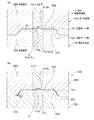
そして、光学部品を精度良く製造することができる成形用金型としては、例えば、図9(a)および(b)に示すように、型閉により第1の金型600と第2の金型700の間にキャビティCを形成し、このキャビティCで製品を射出成形する成形用金型500が知られている(例えば、特許文献1参照)。
この第1の金型600は、キャビティ面610aを有する入れ子610と、入れ子610を外側から保持するとともに、第2の金型700側の下端面622に凹型テーパ部621を有する本体部材620と、から構成されている。
また、第2の金型700は、キャビティ面710aを有する入れ子710と、入れ子710を外側から保持するとともに、第1の金型600側の上端面722に凸型テーパ部721を有する本体部材720と、から構成されている。
As a molding die capable of manufacturing an optical component with high accuracy, for example, as shown in FIGS. 9A and 9B, the
The
Further, the
この成形用金型500では、凹型テーパ部621と凸型テーパ部721の嵌合によって、第1の金型600の入れ子610と第2の金型700の入れ子710の心合わせを行うように構成されている。
前記した従来の成形用金型500では、図9(a)に示すように、型閉時に第1の金型600の下端面622と第2の金型700の上端面722との間に隙間S1が形成されていると、製品の厚み精度が低下してしまう。さらに、その隙間S1が大きい場合には、キャビティC内に供給された材料が隙間S1から流出し、成形後の製品にバリが生じてしまう。そのため、図9(b)に示すように、型閉時に第1の金型600の下端面622と第2の金型700の上端面722との間に隙間が生じないように設計されている。
In the conventional molding die 500 described above, as shown in FIG. 9A, there is a gap between the
しかしながら、第1の金型600の下端面622と、第2の金型700の上端面722とが接するように加工した場合には、加工時の寸法公差の影響により、凹型テーパ部621と凸型テーパ部721の傾斜面の傾きを完全に一致させることが困難となる。そのため、型閉時に凹型テーパ部621の傾斜面と凸型テーパ部721の傾斜面との間に横方向の隙間S2が生じてしまうことになり、第1の金型600と第2の金型700が正確に心合わせされないため、製品の面間偏心精度が低下してしまう。
このように、従来の成形用金型500では、製品の厚み精度および面間偏心精度の両方を高めることが困難であり、製品の成形精度が低下してしまうという問題がある。
However, when processing is performed so that the
Thus, in the
本発明は、かかる問題に鑑みてなされたものであり、製品の厚み精度および面間偏心精度の両方を高めることができる成形用金型を提供することを課題とする。 This invention is made | formed in view of this problem, and makes it a subject to provide the metal mold | die for molding which can improve both the thickness precision of a product, and the surface eccentricity precision.
前記課題を解決するため、本発明は、型閉により形成されたキャビティ内で製品を成形するための成形用金型であって、キャビティ面を有する第1の金型および第2の金型と、型閉時に第1の金型および第2の金型の側周面の少なくとも三方向に当接する複数の位置決め部材と、を備え、少なくとも一つの位置決め部材を第1の金型および第2の金型の側周面に向かって移動させて、各位置決め部材を第1の金型および第2の金型の側周面に当接させ、各位置決め部材によって、第1の金型および第2の金型を挟み込むことにより、第1の金型と第2の金型の心合わせが行われるように構成されていることを特徴としている。 In order to solve the above-described problems, the present invention provides a molding die for molding a product in a cavity formed by mold closing, and includes a first die and a second die having a cavity surface. A plurality of positioning members abutting in at least three directions of the side peripheral surfaces of the first mold and the second mold when the mold is closed, wherein the at least one positioning member is the first mold and the second mold. The positioning members are moved toward the side peripheral surfaces of the molds to bring the positioning members into contact with the side peripheral surfaces of the first mold and the second mold, and the first mold and the second mold are moved by the positioning members. It is characterized in that the first mold and the second mold are aligned by sandwiching the mold.
このように、第1の金型および第2の金型の側周面の少なくとも三方向に当接する複数の位置決め部材によって、第1の金型と第2の金型の心合わせを行うことにより、従来のように第1の金型と第2の金型の嵌合部位によって第1の金型と第2の金型の心合わせが行われないため、第1の金型および第2の金型の嵌合部位の寸法公差に影響されることなく、第1の金型と第2の金型の心合わせを正確に行うことができる。したがって、第1の金型と第2の金型との間に型開閉方向の隙間を形成することなく、第1の金型と第2の金型を閉じるように構成して、製品の厚さ精度を高めるとともに、第1の金型と第2の金型の心合わせを正確に行うことができるため、製品の厚み精度および面間偏心精度の両方を高めることができる。
また、第1の金型および第2の金型に、凹型テーパ部と凸型テーパ部等の嵌合部位を高精度に加工する必要がなくなり、第1の金型および第2の金型の加工が容易になるため、成形用金型の製作コストを低減することができる。
As described above, the first mold and the second mold are aligned by the plurality of positioning members that are in contact with at least three directions of the side peripheral surfaces of the first mold and the second mold. Since the first mold and the second mold are not aligned by the fitting portion of the first mold and the second mold as in the prior art, the first mold and the second mold are not aligned. The first mold and the second mold can be accurately aligned without being affected by the dimensional tolerance of the fitting part of the mold. Accordingly, the first mold and the second mold are closed without forming a gap in the mold opening / closing direction between the first mold and the second mold, so that the thickness of the product is increased. In addition to improving the accuracy, the first mold and the second mold can be accurately aligned, so that both the thickness accuracy and the inter-surface eccentricity accuracy of the product can be increased.
Further, it is not necessary to process the fitting portions such as the concave taper portion and the convex taper portion in the first die and the second die with high accuracy, and the first die and the second die can be formed. Since processing becomes easy, the manufacturing cost of the molding die can be reduced.
なお、型閉時とは、第1の金型と第2の金型が完全に閉じて、型締め力が付与されている状態だけではなく、第1の金型と第2の金型が閉じる途中の状態も含むものである。すなわち、本発明では、第1の金型と第2の金型が閉じる途中で、位置決め部材を第1の金型および第2の金型の側周面に当接させることもできる。この方法では、第1の金型および第2の金型と位置決め部材とが摺動することになるが、第1の金型と第2の金型が完全に閉じた後に、位置決め部材を第1の金型および第2の金型の側周面に当接させる場合には、第1の金型および第2の金型と位置決め部材との摺動を防ぐことができる。 Note that when the mold is closed, not only the first mold and the second mold are completely closed and the clamping force is applied, but also the first mold and the second mold are This includes a state in the middle of closing. That is, in the present invention, the positioning member can be brought into contact with the side peripheral surfaces of the first mold and the second mold while the first mold and the second mold are being closed. In this method, the first mold and the second mold and the positioning member slide, but after the first mold and the second mold are completely closed, the positioning member is moved to the first mold and the second mold. When abutting against the side peripheral surfaces of the first mold and the second mold, sliding between the first mold and the second mold and the positioning member can be prevented.
前記した成形用金型において、第1の金型および第2の金型の側周面には、第1の金型と第2の金型の心合わせが行われた状態で面一となる一対の基準部が少なくとも三組形成され、各位置決め部材には、一対の基準部に密着する当接部が形成されるように構成することができる。 In the molding die described above, the side surfaces of the first mold and the second mold are flush with the first mold and the second mold being aligned. At least three pairs of reference portions are formed, and each positioning member can be configured to be formed with contact portions that are in close contact with the pair of reference portions.
この構成では、第1の金型と第2の金型の側周面が面一となる基準部に密着させる位置決め部材の当接部が、型開閉方向に沿って直線状に加工されることになるため、位置決め部材の当接部を高精度に加工することが容易となり、位置決め部材の加工精度を高めることができるとともに、加工コストを低減することができる。
なお、基準部および当接部は、線状に密着する構成や面状に密着する構成など限定されるものではない。
In this configuration, the contact portion of the positioning member that closely contacts the reference portion where the side peripheral surfaces of the first mold and the second mold are flush with each other is processed linearly along the mold opening / closing direction. Therefore, it becomes easy to process the contact portion of the positioning member with high accuracy, and the processing accuracy of the positioning member can be increased and the processing cost can be reduced.
Note that the reference portion and the contact portion are not limited to a configuration in which the reference portion and the contact portion are in close contact with each other in a linear manner or a configuration in which the reference portion and the contact portion are in close contact with each other.
前記した成形用金型において、位置決め部材は、第1の金型および第2の金型の型開閉方向に対して垂直方向に移動するように構成することができる。 In the molding die described above, the positioning member can be configured to move in a direction perpendicular to the mold opening and closing directions of the first mold and the second mold.
このように、位置決め部材を第1の金型および第2の金型に各入れ子の型開閉方向に対して垂直方向に移動させることにより、位置決め部材を移動させるための機構を簡易な構成にすることができる。 As described above, the mechanism for moving the positioning member is simplified by moving the positioning member in the first mold and the second mold in the direction perpendicular to the mold opening / closing direction of each nesting. be able to.
前記した成形用金型において、位置決め部材を、第1の金型および第2の金型の側周面に向かって案内する傾斜面を備え、位置決め部材を傾斜面に沿ってスライドさせることにより、位置決め部材を第1の金型および第2の金型の側周面に当接させるように構成することができる。 In the above-described molding die, the positioning member includes an inclined surface that guides the positioning member toward the side peripheral surfaces of the first die and the second die, and by sliding the positioning member along the inclined surface, It can comprise so that a positioning member may be contact | abutted to the side peripheral surface of a 1st metal mold | die and a 2nd metal mold | die.
このように、位置決め部材を第1の金型および第2の金型の側周面に向かって案内する傾斜面を備えることにより、型閉方向の力を付与した位置決め部材を、第1の金型および第2の金型の側周面に向かって移動させることができる。これは、成形用金型を複数並べて配置する場合に有効であり、所定領域内に並べることが可能な成形用金型の個数を増やすことができる。 As described above, the positioning member provided with the force in the mold closing direction is provided with the inclined surface that guides the positioning member toward the side peripheral surfaces of the first mold and the second mold. It can be moved toward the side peripheral surfaces of the mold and the second mold. This is effective when a plurality of molding dies are arranged side by side, and the number of molding dies that can be arranged in a predetermined region can be increased.
なお、位置決め部材を第1の金型および第2の金型の側周面に向かって案内する傾斜面としては、例えば、第1の金型または第2の金型の周囲に円錐面を形成する構成や、第1の金型または第2の金型の周囲に平面状の傾斜面を形成する構成など限定されるものではない。
さらに、各位置決め部材が一体の部材に取り付けられているように構成することもでき、この構成では、各位置決め部材を同じタイミングで移動させることができる。
In addition, as an inclined surface for guiding the positioning member toward the side peripheral surfaces of the first mold and the second mold, for example, a conical surface is formed around the first mold or the second mold. However, the present invention is not limited to such a configuration, or a configuration in which a flat inclined surface is formed around the first mold or the second mold.
Furthermore, it can also comprise so that each positioning member may be attached to the integral member, and in this structure, each positioning member can be moved at the same timing.
また、前記した本発明の各構成において、位置決め部材を移動させる機構としては、例えば、各種直動シリンダ(エアシリンダ、油圧シリンダ、ソレノイドコイル等)、圧電素子、ばね部材等の各種アクチュエータによって位置決め部材を移動させる構成がある。また、型閉時の力を利用する構成としては、型閉方向に移動している第1の金型または第2の金型に形成した傾斜面によって位置決め部材を押し出す構成もある。さらに、形状記憶合金の復元力によって位置決め部材を押し出す構成、エア等の流体の注入による中空部材の膨張力によって位置決め部材を押し出す構成など、位置決め部材を移動させる機構は限定されるものではない。 Further, in each configuration of the present invention described above, as a mechanism for moving the positioning member, for example, the positioning member can be operated by various actuators such as various linear cylinders (air cylinders, hydraulic cylinders, solenoid coils, etc.), piezoelectric elements, and spring members. There is a configuration to move. Moreover, as a structure using the force at the time of mold closing, there also exists a structure which extrudes a positioning member with the inclined surface formed in the 1st metal mold | die or 2nd metal mold | die which is moving to the mold closing direction. Further, the mechanism for moving the positioning member is not limited, such as a configuration in which the positioning member is pushed out by the restoring force of the shape memory alloy, and a configuration in which the positioning member is pushed out by the expansion force of the hollow member by injection of fluid such as air.
本発明によれば、従来のように第1の金型と第2の金型の嵌合部位によって第1の金型と第2の金型の心合わせが行われないため、第1の金型および第2の金型の嵌合部位の寸法公差に影響されることなく、第1の金型と第2の金型の心合わせを正確に行うことができる。したがって、第1の金型と第2の金型との間に、型開閉方向の隙間を形成することなく、第1の金型と第2の金型を閉じるように構成して、製品の厚み精度を高めるとともに、第1の金型と第2の金型の心合わせを正確に行うことができるため、製品の厚み精度および面間偏心精度の両方を高めることができる。
また、第1の金型および第2の金型に、凹型テーパ部と凸型テーパ部等の嵌合部位を高精度に加工する必要がなくなり、第1の金型および第2の金型の加工が容易になるため、成形用金型の製作コストを低減することができる。
According to the present invention, since the first mold and the second mold are not centered by the fitting portion of the first mold and the second mold as in the prior art, the first mold The first mold and the second mold can be accurately aligned without being affected by the dimensional tolerance of the fitting portion of the mold and the second mold. Accordingly, the first mold and the second mold are closed without forming a gap in the mold opening / closing direction between the first mold and the second mold, Since the thickness accuracy can be increased and the first mold and the second mold can be accurately aligned, both the thickness accuracy of the product and the inter-surface eccentricity accuracy can be increased.
Further, it is not necessary to process the fitting portions such as the concave taper portion and the convex taper portion in the first die and the second die with high accuracy, and the first die and the second die can be formed. Since processing becomes easy, the manufacturing cost of the molding die can be reduced.
次に、本発明の実施形態について、適宜図面を参照しながら詳細に説明する。
なお、各実施形態の説明において、同一の構成要素に関しては同一の符号を付し、重複した説明は省略するものとする。
また、本実施形態では、本発明をプラスチック光学レンズ(以下、単に「レンズ」という。)の製造に適用した場合について説明する。
Next, embodiments of the present invention will be described in detail with reference to the drawings as appropriate.
In the description of each embodiment, the same constituent elements are denoted by the same reference numerals, and redundant descriptions are omitted.
In the present embodiment, the case where the present invention is applied to the manufacture of a plastic optical lens (hereinafter simply referred to as “lens”) will be described.
[第1実施形態]
はじめに、第1実施形態の成形用金型の構成について説明する。
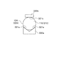
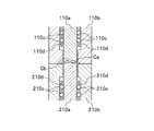
参照する図面において、図1は、第1実施形態の成形用金型を示した図で、(a)は心合わせを行う前の成形用金型の平面図、(b)は図1(a)のA−A断面図である。図2は、第1実施形態の成形用金型を示した図で、(a)は心合わせを行った後の成形用金型の平面図、(b)は図2(a)のB−B断面図である。
[First Embodiment]
First, the configuration of the molding die according to the first embodiment will be described.
In the drawings to be referred to, FIG. 1 is a view showing a molding die of the first embodiment, (a) is a plan view of the molding die before centering, and (b) is FIG. It is AA sectional drawing of). 2A and 2B are diagrams showing the molding die according to the first embodiment, in which FIG. 2A is a plan view of the molding die after centering, and FIG. 2B is B- in FIG. It is B sectional drawing.
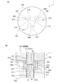
第1実施形態の成形用金型1は、図1(a)および(b)に示すように、型閉により第1の金型100と第2の金型200との間にキャビティCを形成し、このキャビティCでレンズ(特許請求の範囲における「製品」)を成形するものである。第1実施形態では、第1の金型100が第2の金型200に対して鉛直方向(図1(b)の上下方向)に移動することにより、第1の金型100と第2の金型200が開閉自在となっている。また、成形用金型1は、第1の金型100と第2の金型200の心合わせを行うための位置決め部材310を備えている。
In the molding die 1 of the first embodiment, as shown in FIGS. 1A and 1B, a cavity C is formed between the
第1の金型100は、図1(a)および(b)に示すように、下端にキャビティ面Caが形成された入れ子110と、この入れ子110が嵌め入れられる本体部材120とから構成されている。
As shown in FIGS. 1A and 1B, the
入れ子110は、本体部材120とは別部品に構成された金属製の部材であり、円柱状に形成された部材である。この入れ子110の下端にはキャビティ面Caが形成されている。
The
本体部材120は、入れ子110を外側から保持するための金属製の部材であり、その中心に中空部を備える円筒形状を呈している。
本体部材120の中空部には、入れ子110の上側と遊嵌する穴部121が形成されている。穴部121の下端側は、本体部材120の下端面123に開口しており、穴部121に入れ子110を嵌め入れると、入れ子110の下端に形成されたキャビティ面Caが、本体部材120の下端面123から突出するようになっている。
The
A
また、第1の金型100には、キャビティC内でレンズを成形し、第1の金型100と第2の金型200の型開き後に、入れ子110のキャビティ面Caからレンズを離型させるための突き出し機構が設けられている。この突き出し機構は各種公知の構成を用いることができ、本実施形態では図示を省略している。
Further, in the
第2の金型200は、図1(b)に示すように、上端にキャビティ面Cbが形成された入れ子210と、この入れ子210が嵌め入れられる本体部材220とから構成されている。この第2の金型200は、第1の金型100に対向して配置されている。なお、第1の金型100と同一な構成については詳細な説明を省略するものとする。
As shown in FIG. 1B, the
入れ子210の上端にはキャビティ面Cbが形成されており、本体部材120の中空部には、入れ子210の上側と遊嵌する太穴部221と、入れ子210の下側と遊嵌する細穴部222とが形成されている。太穴部221は細穴部222よりも直径が大きく形成されており、本体部材220の太穴部221および細穴部222に入れ子210を嵌め入れると、入れ子210の上端部は細穴部222内から太穴部221内に突出し、入れ子210の上端に形成されたキャビティ面Cbが、本体部材120の上端面223に露出するようになっている。
A cavity surface Cb is formed at the upper end of the
なお、第1の金型100の入れ子110と第2の金型200の入れ子210とは同じ直径に形成されており、各入れ子110,210が同心位置で突き合わされた場合には、入れ子110の外周面124(特許請求の範囲における「側周面」)と、入れ子210の外周面224(特許請求の範囲における「側周面」)とが面一となるように構成されている。このように、各入れ子110,210の心合わせが行われた状態で面一となる一対の外周面124,224を、第1の金型100と第2の金型200の心合わせを行うときの基準部としている。第1実施形態では、入れ子110,210の外周面124,224の全周を基準部としているが、外周面124,224において、後記する位置決め部材310が当接する部位に基準部が形成されていればよい。
The
また、第1の金型100には、図示しない成形機のノズルから溶融したプラスチック材料が供給されるスプルーが設けられ、第2の金型200には、スプルーからキャビティCまでプラスチック材料を供給するためのランナー、ゲート等が設けられているが、本実施形態では図示を省略している。
The
位置決め部材310は、第1の金型100と第2の金型200の心合わせを行うための部材である(図2(a)参照)。ここで、本実施形態において、第1の金型100と第2の金型200の心合わせとは、第1の金型100および第2の金型200全体の位置を調整するものではなく、キャビティCを形成する各入れ子110,210を同心位置に配置することである。
The positioning
この位置決め部材310は、図1(a)および(b)に示すように、型締め時に第1の金型100の入れ子110の外周面124と、第2の金型200の入れ子210の外周面224に当接する金属製の直方体である。位置決め部材310は、第2の金型200の太穴部221内に、各入れ子110,210の外周に沿って120°間隔で三体が配置されており、各入れ子110,210の外周面224の三方向に当接するように構成されている。
As shown in FIGS. 1A and 1B, the positioning
また、位置決め部材310において、成形用金型1の内側に面している当接面311は、図2(a)および(b)に示すように、型開閉方向に平行した平面に形成されている。この当接面311には、各入れ子110,210の心合わせが行われた状態で面一となる一対の外周面124,224(基準部)に対して、型開閉方向に平行して線状に密着する当接部が含まれている。
In the
また、各位置決め部材310・・・は、第2の金型200の太穴部221内に設けられた駆動手段380によって、型開閉方向に対して垂直方向に移動可能となっている。
なお、各位置決め部材310・・・を移動させるための駆動手段380は限定されるものではなく、各種公知の技術を用いることができ、第1実施形態では、第1の金型100と第2の金型200の型閉後に、各位置決め部材310・・・をエアシリンダ等のアクチュエータによって移動させるように構成されている。
Further, each positioning
In addition, the drive means 380 for moving each positioning
そして、型閉後に各位置決め部材310・・・を各入れ子110,210の外周面124,224に向かって移動させたときに、第1の金型100と第2の金型200の軸心位置がずれている場合には、一体または二体の位置決め部材310が各入れ子110,210の外周面124,224(基準部)に押し当てられることになる。これにより、各入れ子110,210は、各位置決め部材310・・・に挟み込まれて横方向に移動し、各入れ子110,210の外周面124,224(基準部)の三方向に、各位置決め部材310・・・の当接部が当接し、各入れ子110,210の軸心が一致した状態で位置決めされて、各入れ子110,210の心合わせが行われる。
その後、第1の金型100と第2の金型200に型締め力を付与して、第1の金型100と第2の金型200を圧接している。
When the
Thereafter, a clamping force is applied to the
ここで、入れ子110の下端と入れ子210の上端とは、僅かに隙間を空けた状態で突き合わされているため、各入れ子110,210の心合わせが行われるときに、入れ子110の下端と入れ子210の上端とが擦れ合って損傷することがない。また、プラスチック光学レンズを成形するための材料となるポリカーボネート、ポリエステル、アクリル等のプラスチック材料は粘性が高いため、キャビティC内に供給されたプラスチック材料が各入れ子110,210の上端と下端の隙間から流出することはない。
また、入れ子110の下端と入れ子210の上端との隙間が大きいとレンズの厚み精度が低下するため、その間隔は3μm以下が好ましく、1μm以下がさらに好ましい。なお、入れ子110の下端と入れ子210の上端との間に隙間を設けない場合には、第1の金型100と第2の金型200に型締め力を付与したときに、各入れ子110,210を移動させることができなくなったり、入れ子110の下端と入れ子210の上端とが擦れ合って磨耗したりしてしまう。
Here, since the lower end of the
In addition, if the gap between the lower end of the
以上のように構成された第1実施形態の成形用金型1では、次のような作用効果を奏する。
第1実施形態の成形用金型1によれば、図2(a)および(b)に示すように、各入れ子110,210の外周面124,224(基準部)の三方向に当接する各位置決め部材310・・・によって、各入れ子110,210の心合わせを行うことにより、第1の金型100と第2の金型200の心合わせが行われる。したがって、従来の成形用金型(図9参照)のように、第1の金型100と第2の金型200の嵌合部位によって、各入れ子110,210の心合わせが行われないため、第1の金型100および第2の金型200の嵌合部位の寸法公差に影響されることなく、第1の金型100と第2の金型200の心合わせを正確に行うことができる。
このように、第1実施形態の成形用金型1では、第1の金型100と第2の金型200との間に、型開閉方向の隙間を形成することなく閉じるように構成して、レンズの厚み精度を高めるとともに、第1の金型100と第2の金型200の心合わせを正確に行うことができるため、レンズの厚み精度および面間偏心精度の両方を高めることができる。
The molding die 1 of the first embodiment configured as described above has the following operational effects.
According to the molding die 1 of the first embodiment, as shown in FIGS. 2A and 2B, each of the outer
As described above, the molding die 1 according to the first embodiment is configured to be closed without forming a gap in the mold opening / closing direction between the
また、従来の成形用金型(図9参照)のように、第1の金型100および第2の金型200に、凹型テーパ部と凸型テーパ部等の嵌合部位を高精度に加工する必要がなくなり、第1の金型100および第2の金型200の加工が容易になるため、成形用金型1の製作コストを低減することができる。
In addition, like the conventional molding die (see FIG. 9), the
また、第1の金型100と第2の金型200とが完全に閉じた後に、各位置決め部材310・・・を各入れ子110,210の外周面124,224に押し当てるように構成されており、各位置決め部材310・・・と各入れ子110,210の外周面124,224とが摺動しないため、各入れ子110,210および各位置決め部材310・・・の損傷を防ぐことができる。
Further, after the
また、位置決め部材310は、型開閉方向に対して垂直方向(横方向)に移動するように構成されているため、位置決め部材310を移動させるための機構を簡易な構成にすることができる。
Further, since the
さらに、第1の金型100と第2の金型200の外周面124,224が面一となる基準部に密着させる位置決め部材310の当接面311が、型開閉方向に沿って直線状に加工されることになるため、当接面311を高精度に加工することが容易となり、位置決め部材310の加工精度を高めることができるとともに、加工コストを低減することができる。
Furthermore, the
以上、本発明の第1実施形態について図面を参照して詳細に説明したが、本発明は前記した第1実施形態に限定されるものではなく、本発明の主旨を逸脱しない範囲で適宜変更が可能である。 As mentioned above, although 1st Embodiment of this invention was described in detail with reference to drawings, this invention is not limited to above-described 1st Embodiment, In the range which does not deviate from the main point of this invention, it changes suitably. Is possible.
例えば、第1実施形態では、レンズを製造するための金型に本発明を適用した例について説明したが、これに限られるものではなく、例えばレンズを保持するための鏡枠を製造するための金型に適用してもよい。 For example, in the first embodiment, an example in which the present invention is applied to a mold for manufacturing a lens has been described. However, the present invention is not limited to this. For example, a lens frame for holding a lens is manufactured. It may be applied to a mold.
また、第1実施形態では、図2(a)に示すように、三体の位置決め部材310・・・を各入れ子110,210の外周面124,224の三方向に当接させて、各入れ子110,210の心合わせを行っているが、各入れ子110,210の少なくとも三方向に位置決め部材310が当接していれば、各入れ子110,210の位置決めを行うことができるため、三体以上の位置決め部材310を設けてもよい。
Moreover, in 1st Embodiment, as shown to Fig.2 (a), three positioning
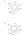
さらに、第1実施形態では、図1(a)に示すように、一体の位置決め部材310に一面の当接面311が設けられているが、図3の平面図に示すように、二面の当接面321a,321aが形成された位置決め部材320aを設け、この位置決め部材320aと、一面の当接面321bが形成された位置決め部材320bとによって、各入れ子110,210を挟み込むように構成することもできる。
Furthermore, in 1st Embodiment, as shown to Fig.1 (a), although the one
また、第1実施形態では、図2(b)に示すように、各入れ子110,210の心合わせが行われた状態で面一となる外周面124,224に、位置決め部材310の当接面311を当接させているが、図4の断面図に示すように、各入れ子110´,210´の直径が異なる場合にも本発明を適用することができる。この場合には、位置決め部材330の当接面331が、各入れ子110´,210´の外周面124,224に密着するように、各入れ子110´,210´の突合せ部位の段差に対応させて、当接面331に段差部を形成している。
なお、当接面331の段差部を各入れ子110´,210´の突合せ部位の段差よりも上方に形成した場合には、各入れ子110´,210´の突合せ部位の段差と、当接面331の段差部とが直接嵌り合わないため、位置決め部材330の段差部を高精度に加工する必要がなくなり、位置決め部材330を容易に加工することができる。
Moreover, in 1st Embodiment, as shown in FIG.2 (b), the contact surface of the
In addition, when the level | step-difference part of contact | abutting
また、第1実施形態では、図2(a)および(b)に示すように、三体の位置決め部材310・・・を移動させているが、各位置決め部材310・・・のうち少なくとも一体を移動させ、この一体の位置決め部材310によって各入れ子110,210を三体の位置決め部材310・・・の間に押し込むことにより、各入れ子110,210の外周面124,224の三方向に各位置決め部材310・・・を当接させることもできる。
Moreover, in 1st Embodiment, as shown to Fig.2 (a) and (b), although the three
また、第1実施形態では、図2(b)に示すように、駆動手段380として、エアシリンダ等のアクチュエータ(図示せず)を用いているが、これに限定されるものではなく、例えば、油圧シリンダ、ソレノイドコイル、圧電素子、ばね部材等の各種アクチュエータを用いることができる。
また、第1の金型100や第2の金型200の本体部材120,220内に設けた形状記憶合金の復元力によって位置決め部材310(図1(b)参照)を押し出すように構成したり、本体部材120,220内に設けた中空部材にエア等の流体を注入し、その膨張力によって位置決め部材310(図1(b)参照)を押し出すように構成したりすることができる。
Further, in the first embodiment, as shown in FIG. 2B, an actuator (not shown) such as an air cylinder is used as the driving means 380. However, the present invention is not limited to this. For example, Various actuators such as a hydraulic cylinder, a solenoid coil, a piezoelectric element, and a spring member can be used.
Further, the positioning member 310 (see FIG. 1B) is pushed out by the restoring force of the shape memory alloy provided in the
また、第1実施形態では、図2(b)に示すように、位置決め部材310の当接面311を、型開閉方向に平行となる平面に形成しているが、図5(a)の平面図に示す位置決め部材350のように、円形断面の各入れ子110,210の外周面124,224に沿って、円弧状の曲面で当接面351を形成してもよい。この構成では、平面状の当接面311(図2(b)参照)と比較して接触面積が大きくなるため、位置決め部材350を各入れ子110,210の外周面124,224に対して確実に押し当てることができる。なお、当接面351の曲率は、各入れ子110,210の外周面124,224の曲率よりも大きいことが望ましい。このように構成した場合には、当接面351の円周方向の端部が各入れ子110,210の外周面124,224に接触し難くなるとともに、当接面351が各入れ子110,210の外周面124,224を押し出す方向を特定することができる。
In the first embodiment, as shown in FIG. 2B, the
また、図5(b)の平面図に示す位置決め部材360のように、各入れ子110,210の外周面124,224の一部が入り込むように、平面視でV字形状に形成された当接面361を形成することもできる。
Further, like the
また、第1実施形態では、図2(b)に示すように、各入れ子110,210の心合わせが行われるときに、第1の金型100および第2の金型200の両方が横方向に移動するように構成されているが、一方の金型を固定し、この固定側の金型に対して、他方の金型が移動することにより、各入れ子110,210の心合わせが行われるように構成することができる。なお、この構成では、三体の位置決め部材360・・・が移動して他方の金型を移動させることになる。
Moreover, in 1st Embodiment, as shown in FIG.2 (b), when each nest | insert 110,210 is centered, both the 1st metal mold | die 100 and the 2nd metal mold | die 200 are horizontal direction. Although one mold is fixed and the other mold moves with respect to the fixed mold, the
また、第1実施形態では、図1(b)に示すように、第1の金型100と第2の金型200が鉛直方向に型開閉するたて型の成形機に適用されているが、第1の金型100と第2の金型200が水平方向に型開閉する横型の成形機に適用することもできる。この構成では、一方(上側)の金型が重力によって他方(下側)の金型に押し付けられることがないため、型閉後に各入れ子110,210の心合わせを行ったときの各入れ子110,210の突合せ部位の磨耗を防ぐことができる。
In the first embodiment, as shown in FIG. 1B, the
また、第1実施形態では、図1(b)に示すように、第2の金型200に位置決め部材310とその駆動手段380を設けているが、第1の金型100に設けてもよい。
また、第1の金型100および第2の金型200の本体部材120,220は、円筒形状に限定されるものではなく、直方体等の各種形状によって構成することができる。
また、第1実施形態では、第2の金型200に径の異なる太穴部221と細穴部222とが形成されているが、同径の穴部にすることもできる。
また、一体の成形用金型1の内部に複数のキャビティCが形成されるように構成することもできる。
In the first embodiment, as shown in FIG. 1B, the positioning
Moreover, the
Further, in the first embodiment, the
In addition, a plurality of cavities C can be formed inside the integral molding die 1.
さらに、型開後に入れ子110のキャビティ面Caからレンズを離型させるための突き出し機構を第1の金型100に設けているが、第2の金型200に設けてもよい。
また、第1実施形態では、各入れ子110,210がそれぞれ一体の部材によって形成されているが、図6の断面図に示すように、レンズの光学面を成形するための中央の入れ子110a,210aと、レンズのフランジ部を成形するための外側の入れ子110b,210bとに分割し、円筒形状の外側の入れ子110b,210b内に、中央の入れ子110a,210aが嵌め込まれた構成にすることもできる。この構成では、外側の入れ子110b,210bと、中央の入れ子110a,210aとの間に、複数の球状体110c,210cおよびその球状体110c,210cを保持するリテーナ110d,210dを介在させて心合わせを行っている。そして、型開後には、中央の入れ子110a,210aに対して外側の入れ子110b,210bをスライドさせて突き出すことにより、中央の入れ子110a,110bのキャビティ面Ca,Cbからレンズを離型させることができる。
Further, although a protruding mechanism for releasing the lens from the cavity surface Ca of the
In the first embodiment, each
[第2実施形態]
次に、第2実施形態の成形用金型の構成について説明する。
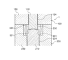
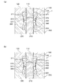
図7は、第2実施形態の成形用金型を示した図で、(a)は心合わせを行う前の成形用金型の断面図、(b)は心合わせを行った後の成形用金型の断面図である。
[Second Embodiment]
Next, the configuration of the molding die according to the second embodiment will be described.
7A and 7B are diagrams showing a molding die according to the second embodiment, in which FIG. 7A is a cross-sectional view of the molding die before centering, and FIG. 7B is a molding after centering. It is sectional drawing of a metal mold | die.
第2実施形態の成形用金型1´は、図2(a)に示す第1実施形態の成形用金型1と略同様の構成であり、位置決め部材を移動させる構成が異なっている。
第2実施形態の成形用金型1´では、図7(a)に示すように、各位置決め部材370・・・に対して型開閉方向の力が付与されるように、すなわち、各入れ子110,210の外周面124,224に平行方向の力が付与されるように構成されており(図7(b)参照)、型閉方向に移動しようとする各位置決め部材370・・・を、各入れ子110,210の外周面124,224に向かって案内する傾斜面400が各入れ子110,210の周囲に形成されている。
The molding die 1 ′ of the second embodiment has substantially the same configuration as the molding die 1 of the first embodiment shown in FIG. 2A, and the configuration for moving the positioning member is different.
In the molding die 1 ′ of the second embodiment, as shown in FIG. 7A, a force in the mold opening / closing direction is applied to each positioning
傾斜面400は、型閉時に、第1の金型100の入れ子110の下端部と、第2の金型200の入れ子210の上端部の周囲に形成される逆円錐面である。この傾斜面400は、第2の金型200の本体部材220の太穴部221´の内周側面に形成されている。
The
位置決め部材370の外側の面(傾斜面400と当接する面)には、傾斜面400に対応した傾斜面が形成されており、位置決め部材370は傾斜面400上を上下方向にスライド可能となっている。なお、位置決め部材370を移動させるための駆動手段380は、第1実施形態と同様に限定されるものではなく、第2実施形態では、第2の金型200に設けられた駆動手段380が、型閉時に位置決め部材370を下方に引っ張るように構成されている。
An inclined surface corresponding to the
そして、図7(b)に示すように、各駆動手段380が各位置決め部材370・・・を下方に向かって引っ張ったときには、各位置決め部材370・・・は傾斜面400に沿ってスライドして、各入れ子110,210の外周面124,224に向かって移動することになり、各位置決め部材370・・・の当接面371が各入れ子110,210の外周面124,224に当接することにより、各入れ子110,210の心合わせが行われ、第1の金型100と第2の金型200の心合わせが行われることになる。
As shown in FIG. 7 (b), when each driving means 380 pulls each positioning
このように、第2実施形態の成形用金型1´では、各入れ子110,210の外周面124,224に平行して型閉方向の力が付与された各位置決め部材370・・・を、各入れ子110,210の外周面124,224に向かって案内する傾斜面400が形成されているため、成形用金型1´の横幅を小さくすることができる。これは、成形用金型1´を複数並べて配置する場合に有効であり、所定領域内に並べることが可能な成形用金型1´の個数を増やすことができる。
As described above, in the molding die 1 ′ of the second embodiment, the
以上、本発明の第2実施形態について図面を参照して詳細に説明したが、前記した第2実施形態に限定されるものではなく、第1実施形態と同様に、本発明の主旨を逸脱しない範囲で適宜変更が可能である。 As described above, the second embodiment of the present invention has been described in detail with reference to the drawings. However, the present invention is not limited to the second embodiment described above, and does not depart from the gist of the present invention as in the first embodiment. Changes can be made as appropriate within the range.
例えば、第2実施形態では、図7(a)に示すように、各入れ子110,210の周囲に逆円錐面の傾斜面400を形成しているが、各入れ子110,210の周囲に平面状の傾斜面を複数形成することにより、駆動手段380によって下方に向かって引っ張られた各位置決め部材370・・・を案内するように構成することもできる。
For example, in the second embodiment, as shown in FIG. 7A, an
また、第2実施形態では、図7(a)に示すように、太穴部221´の内周面全体に傾斜面400を形成しているが、太穴部221´の下部に傾斜面400を形成し、太穴部221´の上部は鉛直面に形成してもよい。
なお、第2実施形態では第2の金型200の太穴部221´に逆円錐面の傾斜面400を形成しているが、第1の金型100に円錐面の傾斜面を形成し、その傾斜面上をスライドするように、第1の金型100に位置決め部材を設けることもできる。
Moreover, in 2nd Embodiment, as shown to Fig.7 (a), although the
In the second embodiment, the
また、第2実施形態では、第2の金型200に設けられた駆動手段380によって、位置決め部材370を引っ張っているが、第1の金型100に駆動手段を設け、位置決め部材370を押し出すように構成することもできる。
In the second embodiment, the positioning
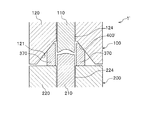
さらに、図8の断面図に示すように、第1の金型100の穴部121の内周側面に円錐形状の傾斜面400´を形成し、型閉時に第1の金型100を下方に向かって移動させたときに、位置決め部材370が傾斜面400´上をスライドしながら、各入れ子110,210の外周面124,224に向かって押し出されるように構成することより、位置決め部材370を移動させるための駆動手段を別途設けることなく、位置決め部材370を各入れ子110,210の外周面124,224に当接させることができる。
Further, as shown in the cross-sectional view of FIG. 8, a conical
また、第2実施形態では、図7(a)に示すように、一体の位置決め部材370に対して一基の駆動手段380を設けているが、複数の位置決め部材370・・・を一基の駆動手段によって移動させるように構成することができる。さらには、一基の成形用金型1´に複数の入れ子110,210を設けた構成では、異なる入れ子110,210の位置決め部材370を、一基の駆動手段によって移動させることもできる。
Moreover, in 2nd Embodiment, as shown to Fig.7 (a), although the one drive means 380 is provided with respect to the
1 成形用金型
100 第1の金型
110 入れ子
120 本体部材
124 外周面
200 第2の金型
210 入れ子
220 本体部材
224 外周面
310 位置決め部材
311 当接面
380 駆動手段
400 傾斜面
C キャビティ
Ca キャビティ面
Cb キャビティ面
DESCRIPTION OF
Claims (4)
キャビティ面を有する第1の金型および第2の金型と、
型閉時に前記第1の金型および前記第2の金型の側周面の少なくとも三方向に当接する複数の位置決め部材と、を備え、
少なくとも一つの前記位置決め部材を前記第1の金型および前記第2の金型の側周面に向かって移動させて、前記各位置決め部材を前記第1の金型および前記第2の金型の側周面に当接させ、前記各位置決め部材によって、前記第1の金型および前記第2の金型を挟み込むことにより、前記第1の金型と前記第2の金型の心合わせが行われるように構成されていることを特徴とする成形用金型。 A mold for molding a product in a cavity formed by mold closing,
A first mold and a second mold having a cavity surface;
A plurality of positioning members that come into contact with at least three directions of the side peripheral surfaces of the first mold and the second mold when the mold is closed;
At least one positioning member is moved toward the side peripheral surfaces of the first mold and the second mold, and the positioning members are moved to the first mold and the second mold. The first mold and the second mold are aligned by abutting against the side peripheral surface and sandwiching the first mold and the second mold by the positioning members. A mold for molding, characterized in that it is configured as described above.
前記各位置決め部材には、前記一対の基準部に密着する当接部が形成されていることを特徴とする請求項1に記載の成形用金型。 A pair of reference portions that are flush with each other on the side surfaces of the first mold and the second mold when the first mold and the second mold are aligned. At least three sets are formed,
The molding die according to claim 1, wherein each positioning member is formed with a contact portion that is in close contact with the pair of reference portions.
Priority Applications (3)
| Application Number | Priority Date | Filing Date | Title |
|---|---|---|---|
| JP2006011515A JP4758771B2 (en) | 2006-01-19 | 2006-01-19 | Mold for molding |
| US11/650,968 US7891965B2 (en) | 2006-01-19 | 2007-01-09 | Mold |
| CN2007100040117A CN101003161B (en) | 2006-01-19 | 2007-01-19 | Mold |
Applications Claiming Priority (1)
| Application Number | Priority Date | Filing Date | Title |
|---|---|---|---|
| JP2006011515A JP4758771B2 (en) | 2006-01-19 | 2006-01-19 | Mold for molding |
Publications (2)
| Publication Number | Publication Date |
|---|---|
| JP2007190823A true JP2007190823A (en) | 2007-08-02 |
| JP4758771B2 JP4758771B2 (en) | 2011-08-31 |
Family
ID=38263474
Family Applications (1)
| Application Number | Title | Priority Date | Filing Date |
|---|---|---|---|
| JP2006011515A Expired - Fee Related JP4758771B2 (en) | 2006-01-19 | 2006-01-19 | Mold for molding |
Country Status (3)
| Country | Link |
|---|---|
| US (1) | US7891965B2 (en) |
| JP (1) | JP4758771B2 (en) |
| CN (1) | CN101003161B (en) |
Families Citing this family (5)
| Publication number | Priority date | Publication date | Assignee | Title |
|---|---|---|---|---|
| JP4758772B2 (en) * | 2006-01-19 | 2011-08-31 | 富士フイルム株式会社 | Mold for molding and molding method |
| WO2009016992A1 (en) * | 2007-08-01 | 2009-02-05 | Konica Minolta Opto, Inc. | Shaping metal mold and process for producing optical element |
| TW201034829A (en) * | 2009-03-27 | 2010-10-01 | Kinik Co | Mold of optical lens |
| US20130235334A1 (en) * | 2011-08-31 | 2013-09-12 | Michael F. Widman | Ophthalmic lens forming optic |
| CN112873737B (en) * | 2020-12-23 | 2022-06-17 | 青岛三昌精密机械有限公司 | Plastic injection mold with locking mechanical system |
Citations (4)
| Publication number | Priority date | Publication date | Assignee | Title |
|---|---|---|---|---|
| JPH0375230A (en) * | 1989-08-18 | 1991-03-29 | Olympus Optical Co Ltd | Apparatus for centering metallic mold |
| JPH10182173A (en) * | 1996-12-26 | 1998-07-07 | Canon Inc | Glass molding, glass molding method and glass molding apparatus |
| JPH11157854A (en) * | 1997-11-26 | 1999-06-15 | Canon Inc | Method and apparatus for molding optical element |
| JP2004262734A (en) * | 2003-03-04 | 2004-09-24 | Victor Co Of Japan Ltd | Method of forming optical lens and metal mold for optical lens |
Family Cites Families (6)
| Publication number | Priority date | Publication date | Assignee | Title |
|---|---|---|---|---|
| US3720491A (en) * | 1970-07-15 | 1973-03-13 | Burroughs Corp | Apparatus for forming articles from powdered metal |
| JP3501580B2 (en) * | 1995-04-20 | 2004-03-02 | キヤノン株式会社 | Optical element molding method and molding apparatus |
| US5987922A (en) * | 1997-05-19 | 1999-11-23 | Hoya Corporation | Manufacturing method for molded glass articles |
| JP3869239B2 (en) * | 2001-09-28 | 2007-01-17 | Hoya株式会社 | Optical element press molding apparatus and optical element manufacturing method |
| JP2004196651A (en) * | 2002-12-04 | 2004-07-15 | Fuji Electric Device Technology Co Ltd | Method and apparatus for manufacturing glass substrate for storage medium, glass substrate for storage medium, and storage medium |
| JP4121365B2 (en) | 2002-12-18 | 2008-07-23 | 株式会社東伸精工 | Injection mold for plastic optical lens and method for producing plastic optical lens |
-
2006
- 2006-01-19 JP JP2006011515A patent/JP4758771B2/en not_active Expired - Fee Related
-
2007
- 2007-01-09 US US11/650,968 patent/US7891965B2/en not_active Expired - Fee Related
- 2007-01-19 CN CN2007100040117A patent/CN101003161B/en not_active Expired - Fee Related
Patent Citations (4)
| Publication number | Priority date | Publication date | Assignee | Title |
|---|---|---|---|---|
| JPH0375230A (en) * | 1989-08-18 | 1991-03-29 | Olympus Optical Co Ltd | Apparatus for centering metallic mold |
| JPH10182173A (en) * | 1996-12-26 | 1998-07-07 | Canon Inc | Glass molding, glass molding method and glass molding apparatus |
| JPH11157854A (en) * | 1997-11-26 | 1999-06-15 | Canon Inc | Method and apparatus for molding optical element |
| JP2004262734A (en) * | 2003-03-04 | 2004-09-24 | Victor Co Of Japan Ltd | Method of forming optical lens and metal mold for optical lens |
Also Published As
| Publication number | Publication date |
|---|---|
| CN101003161A (en) | 2007-07-25 |
| US20070166426A1 (en) | 2007-07-19 |
| JP4758771B2 (en) | 2011-08-31 |
| US7891965B2 (en) | 2011-02-22 |
| CN101003161B (en) | 2011-06-08 |
Similar Documents
| Publication | Publication Date | Title |
|---|---|---|
| CN101505942B (en) | Optical Component Forming Device | |
| CN103025496A (en) | Forming device and forming method | |
| US7731874B2 (en) | Method of molding optical component | |
| WO2014162770A1 (en) | Lens unit structure for molded lens, and die for molding molded lens | |
| US7891965B2 (en) | Mold | |
| US7594808B2 (en) | Mold and molding method | |
| JP2003231159A (en) | Injection mold for plastic optical lens and method for manufacturing plastic optical lens | |
| JP2008183754A (en) | Lens mold | |
| JP2003175532A (en) | Injection mold for plastic optical lens and method for manufacturing plastic optical lens | |
| JP4495585B2 (en) | Resin lens mold | |
| JPH08276470A (en) | Injection mold | |
| JP4142485B2 (en) | Mold equipment | |
| JP4773789B2 (en) | Mold for molding and manufacturing method thereof | |
| JP4590135B2 (en) | Mold for molding | |
| JP2006327005A (en) | Mold and manufacturing method of molded product | |
| JP3760464B2 (en) | Mold equipment for molding | |
| JP2004168011A (en) | Injection mold and optical component | |
| US20080308957A1 (en) | Method and apparatus for forming a miniature lens | |
| JP2007196441A (en) | Mold for molding and molding method | |
| JP2007125731A (en) | Mold for molding | |
| JP4574804B2 (en) | Mold device for optical element having rotationally asymmetric surface | |
| JP2007111917A (en) | Mold for molding and method for assembling mold for molding | |
| JP2007111959A (en) | Mold for molding | |
| JP2011189564A (en) | Mold and molding method | |
| JP2007111980A (en) | Mold for molding |
Legal Events
| Date | Code | Title | Description |
|---|---|---|---|
| A621 | Written request for application examination |
Free format text: JAPANESE INTERMEDIATE CODE: A621 Effective date: 20080708 |
|
| A977 | Report on retrieval |
Free format text: JAPANESE INTERMEDIATE CODE: A971007 Effective date: 20110128 |
|
| A131 | Notification of reasons for refusal |
Free format text: JAPANESE INTERMEDIATE CODE: A131 Effective date: 20110208 |
|
| A521 | Written amendment |
Free format text: JAPANESE INTERMEDIATE CODE: A523 Effective date: 20110408 |
|
| A01 | Written decision to grant a patent or to grant a registration (utility model) |
Free format text: JAPANESE INTERMEDIATE CODE: A01 Effective date: 20110510 |
|
| A61 | First payment of annual fees (during grant procedure) |
Free format text: JAPANESE INTERMEDIATE CODE: A61 Effective date: 20110603 |
|
| R150 | Certificate of patent or registration of utility model |
Free format text: JAPANESE INTERMEDIATE CODE: R150 |
|
| FPAY | Renewal fee payment (event date is renewal date of database) |
Free format text: PAYMENT UNTIL: 20140610 Year of fee payment: 3 |
|
| R250 | Receipt of annual fees |
Free format text: JAPANESE INTERMEDIATE CODE: R250 |
|
| R250 | Receipt of annual fees |
Free format text: JAPANESE INTERMEDIATE CODE: R250 |
|
| R250 | Receipt of annual fees |
Free format text: JAPANESE INTERMEDIATE CODE: R250 |
|
| LAPS | Cancellation because of no payment of annual fees |