JP2007190248A - Pachinko game machine - Google Patents

Pachinko game machine Download PDF

Info

Publication number
JP2007190248A
JP2007190248A JP2006012152A JP2006012152A JP2007190248A JP 2007190248 A JP2007190248 A JP 2007190248A JP 2006012152 A JP2006012152 A JP 2006012152A JP 2006012152 A JP2006012152 A JP 2006012152A JP 2007190248 A JP2007190248 A JP 2007190248A
Authority
JP
Japan
Prior art keywords
game board
symbol display
cleaning
cleaning port
case
Prior art date
Legal status (The legal status is an assumption and is not a legal conclusion. Google has not performed a legal analysis and makes no representation as to the accuracy of the status listed.)
Granted
Application number
JP2006012152A
Other languages
Japanese (ja)
Other versions
JP4887798B2 (en
Inventor
Imahito Murase
今人 村瀬
Current Assignee (The listed assignees may be inaccurate. Google has not performed a legal analysis and makes no representation or warranty as to the accuracy of the list.)
Okumura Yu Ki Co Ltd
Original Assignee
Okumura Yu Ki Co Ltd
Priority date (The priority date is an assumption and is not a legal conclusion. Google has not performed a legal analysis and makes no representation as to the accuracy of the date listed.)
Filing date
Publication date
Application filed by Okumura Yu Ki Co Ltd filed Critical Okumura Yu Ki Co Ltd
Priority to JP2006012152A priority Critical patent/JP4887798B2/en
Publication of JP2007190248A publication Critical patent/JP2007190248A/en
Application granted granted Critical
Publication of JP4887798B2 publication Critical patent/JP4887798B2/en
Expired - Fee Related legal-status Critical Current
Anticipated expiration legal-status Critical

Links

Images

Abstract

<P>PROBLEM TO BE SOLVED: To prevent dimming of the display in an ornament symbol display caused by the influence of dust. <P>SOLUTION: The pachinko game machine has a cleaning port 68 in a rear gutter, and the cleaning port 68 is opened/closed by a right rear gutter 63 of the rear gutter. Accordingly, the rear face of a game board and the liquid crystal display screen of the ornament symbol display can be easily cleaned by opening the cleaning port 68 by turning the right rear gutter 63 without detaching the game board from the ornament symbol display, and inserting a cleaning tool 161 into a closed space 160 through the cleaning port 68 from outside the closed space 160. <P>COPYRIGHT: (C)2007,JPO&INPIT

Description

本発明は、透光性の遊技盤を備えたパチンコ遊技機に関する。   The present invention relates to a pachinko gaming machine provided with a translucent gaming board.

上記パチンコ遊技機には遊技盤の後方に図柄表示器を配置し、前方から遊技盤を通して図柄表示器の表示内容を視認できるように構成したものがある。この構成の場合、図柄表示器と遊技盤との間に枠部材を介在し、図柄表示器で発生する熱が遊技盤側へ伝わることを枠部材によって抑えている。
特開2005−152579号公報
Some of the pachinko gaming machines are configured such that a symbol display is arranged behind the game board so that the display contents of the symbol display can be visually recognized through the game board from the front. In this configuration, a frame member is interposed between the symbol display and the game board, and the frame member prevents heat generated by the symbol display from being transmitted to the game board.
JP 2005-152579 A

従来のパチンコ遊技機では盤替え時に図柄表示器を残したまま遊技盤を交換することができるように遊技盤が図柄表示器に対して着脱可能にされているので、遊技盤を図柄表示器から取外すことで遊技盤の後面および図柄表示器の表示画面の双方を清掃することができる。この従来のパチンコ遊技機は透光性の遊技盤を別の透光性の遊技盤に交換することはできるが、透光性の遊技盤およびベニヤ製の遊技盤を相互に交換することはできない。これに対して盤替え時に遊技盤を図柄表示器ごと交換する構成の場合には透光性の遊技盤およびベニヤ製の遊技盤を相互に交換することができる。この構成の場合、遊技盤と図柄表示器と枠部材の3部材をまとめて交換できるように遊技盤と図柄表示器と枠部材の3部材が相互に分解不能に接合されているので、遊技盤を図柄表示器から取外すことが困難である。このため、遊技盤の後面および図柄表示器の表示画面をいずれも容易に清掃することができないので、図柄表示器の表示内容が遊技盤の後面に付着した埃の影響で不鮮明になったり、あるいは、図柄表示器の表示画面に付着した埃の影響で不鮮明になる虞れがある。   In conventional pachinko machines, the game board is detachable from the symbol display so that the game board can be replaced while leaving the symbol display when changing the board. By removing, it is possible to clean both the rear surface of the game board and the display screen of the symbol display. This conventional pachinko gaming machine can exchange a translucent gaming board with another translucent gaming board, but cannot exchange a translucent gaming board and a veneer gaming board with each other. . On the other hand, in the case of a configuration in which the game board is exchanged together with the symbol display when changing the board, the translucent game board and the veneer game board can be exchanged with each other. In this configuration, the game board, the symbol display, and the frame member are joined to each other so that the game board, the symbol display, and the frame member can be exchanged together. Is difficult to remove from the symbol display. For this reason, neither the back of the game board nor the display screen of the symbol display can be easily cleaned, so the display content of the design display becomes unclear due to the dust adhering to the back of the game board, or There is a possibility that the image becomes unclear due to the effect of dust adhering to the display screen of the symbol display.

本発明は上記事情に鑑みてなされたものであり、その目的は、図柄表示器の表示内容が埃の影響で不鮮明になることを防止することができるパチンコ遊技機を提供することにある。   The present invention has been made in view of the above circumstances, and an object of the present invention is to provide a pachinko gaming machine that can prevent the display content of a symbol display from becoming unclear due to the influence of dust.

<請求項1記載のパチンコ遊技機の説明>
請求項1記載のパチンコ遊技機は[1]遊技盤〜[5]開閉部材を備えたところに特徴を有する。
・ 遊技盤は透光性を有するものであり、図2の符号30は遊技盤の一例である。
[2]図柄表示器は遊技盤の後方に設けられたものであり、大当りおよび外れを識別するための識別図柄が表示される表示画面を有している。図3の装飾図柄表示器140は図柄表示器の一例であり、装飾図柄表示器140の液晶画面141は表示画面に相当する。この液晶画面141は3列の図柄要素からなる装飾図柄が表示されるものであり、装飾図柄は大当りおよび外れを識別するための識別図柄に相当する。
[3]枠部材は遊技盤と図柄表示器との間に設けられたものであり、図柄表示器の表示画面を取囲む枠状をなしている。この枠部材と遊技盤と図柄表示器の3部材は相互に接合されたものであり、枠部材と遊技盤と図柄表示器の間にはこれら3部材で囲まれた閉鎖空間が形成される。図5の符号160は閉鎖空間の一例であり、図2のスペーサ150は枠部材の一例である。このスペーサ150は、図3に示すように、第1の枠部材に相当する前側の裏樋60および第2の枠部材に相当する後側の液晶ステー90を相互に接合することから構成されている。
[4]清掃口は枠部材に設けられた空間部を称するものであり、閉鎖空間の内部には図柄表示器の表示画面または遊技盤の後面を清掃する清掃具が閉鎖空間の外部から清掃口を通して挿入可能にされている。図6の符号68は清掃口の一例であり、清掃口68はスペーサ150のうち前側の裏樋60に形成されている。図6の符号161は閉鎖空間160の外部から清掃口68を通して閉鎖空間160の内部に挿入される清掃具の一例であり、清掃具161は遊技盤30の後面および図柄表示器140の表示画面141の双方を清掃するためのものである。
[5]開閉部材は枠部材に設けられたものであり、清掃口を開放状態および閉鎖状態に相互に切換える蓋として機能する。このため、遊技盤と図柄表示器と枠部材が相互に接合された構成であっても遊技盤を図柄表示器から取外すことなく開閉部材を操作することで清掃口を開放し、閉鎖空間の外部から清掃口を通して閉鎖空間の内部に清掃具を挿入することができる。従って、遊技盤の後面および図柄表示器の表示画面のそれぞれを容易に清掃することができるので、図柄表示器の表示内容が埃の影響で不鮮明になることを防止できる。しかも、遊技盤の後面および図柄表示器の表示画面をいずれも清掃しないときには清掃口を閉鎖しておくことができるので、閉鎖空間の外部から内部に清掃口を通して埃が侵入することを抑えることができる。図5の右部裏樋63は開閉部材の一例であり、垂直な閉鎖状態になることに基づいて清掃口68を閉鎖状態に切換え、水平な開放状態になることに基づいて清掃口68を開放状態に切換える。
<請求項2記載のパチンコ遊技機の説明>
請求項2記載のパチンコ遊技機は開閉部材を枠部材のうち図柄表示器の表示画面の左側面に沿って縦方向へ延びる一部または右側面に沿って縦方向へ延びる一部から構成したものである。この開閉部材は清掃口を閉鎖する閉鎖状態および清掃口を開放する開放状態相互間で回動可能に枠部材の残りの部分に連結されているので、開閉部材を容易に開閉操作することが可能になる。図5の右部裏樋63は枠部材150のうち図柄表示器140の表示画面141の右側面に沿って縦方向へ延びる一部から構成された開閉部材の一例であり、残りの部分である上部裏樋64に回動可能に連結されている。
<Description of the pachinko gaming machine according to claim 1>
The pachinko gaming machine according to claim 1 is characterized in that it includes [1] game board to [5] opening / closing member.
-The game board has translucency, and the code | symbol 30 of FIG. 2 is an example of a game board.
[2] The symbol display is provided at the rear of the game board and has a display screen on which identification symbols for identifying the big hits and misses are displayed. The decorative symbol display 140 in FIG. 3 is an example of a symbol display, and the liquid crystal screen 141 of the decorative symbol display 140 corresponds to a display screen. The liquid crystal screen 141 displays a decorative symbol composed of three rows of symbol elements, and the decorative symbol corresponds to an identification symbol for identifying a big hit or miss.
[3] The frame member is provided between the game board and the symbol display, and has a frame shape surrounding the display screen of the symbol display. The three members of the frame member, the game board, and the symbol display are joined together, and a closed space surrounded by these three members is formed between the frame member, the game board, and the symbol display. Reference numeral 160 in FIG. 5 is an example of a closed space, and the spacer 150 in FIG. 2 is an example of a frame member. As shown in FIG. 3, the spacer 150 is configured by joining a front back wall 60 corresponding to the first frame member and a rear liquid crystal stay 90 corresponding to the second frame member to each other. Yes.
[4] The cleaning port refers to a space provided in the frame member, and a cleaning tool for cleaning the display screen of the symbol display or the rear surface of the game board is provided inside the closed space from the outside of the closed space. Is made insertable through. Reference numeral 68 in FIG. 6 is an example of the cleaning port, and the cleaning port 68 is formed in the back wall 60 of the front side of the spacer 150. Reference numeral 161 in FIG. 6 is an example of a cleaning tool inserted from the outside of the closed space 160 into the closed space 160 through the cleaning port 68, and the cleaning tool 161 is the rear surface of the game board 30 and the display screen 141 of the symbol display 140. It is for cleaning both.
[5] The opening / closing member is provided on the frame member, and functions as a lid for switching the cleaning port between the open state and the closed state. Therefore, even if the game board, the symbol display, and the frame member are joined together, the cleaning port is opened by operating the opening / closing member without removing the game board from the symbol display, and the outside of the closed space. The cleaning tool can be inserted into the closed space through the cleaning port. Therefore, each of the rear surface of the game board and the display screen of the symbol display can be easily cleaned, so that the display content of the symbol display can be prevented from becoming unclear due to the influence of dust. In addition, since the cleaning port can be closed when neither the rear surface of the game board nor the display screen of the symbol display is cleaned, it is possible to prevent dust from entering through the cleaning port from the outside of the closed space. it can. 5 is an example of an opening / closing member. The cleaning port 68 is switched to a closed state based on a vertical closed state, and the cleaning port 68 is opened based on a horizontal open state. Switch to state.
<Description of the pachinko gaming machine according to claim 2>
The pachinko gaming machine according to claim 2, wherein the opening / closing member is constituted by a part of the frame member extending in the vertical direction along the left side of the display screen of the symbol display or a part extending in the vertical direction along the right side. It is. Since the opening / closing member is connected to the remaining part of the frame member so as to be rotatable between a closed state in which the cleaning port is closed and an open state in which the cleaning port is opened, the opening / closing member can be easily opened / closed. become. 5 is an example of an opening / closing member formed of a part of the frame member 150 extending in the vertical direction along the right side of the display screen 141 of the symbol display 140, and is the remaining part. The upper back casing 64 is pivotally connected.

図1の外枠1はパチンコホールの台島に設置されるものであり、前後面が開口する四角筒状をなしている。この外枠1には内枠2が左側部の垂直な軸3を中心に回動可能に装着されている。この内枠2は外枠1の前端面に接触する閉鎖状態および外枠1の前端面から前方へ離間する開放状態に相互に回動操作されるものであり、図1は内枠2を閉鎖状態で示している。この内枠2は、図2に示すように、前後面が開口する四角筒状をなすものであり、内枠2の下端部にはレール台4が形成され、内枠2の内部にはレール台4の上方に位置して遊技盤収納部5が形成されている。レール台4は発射レールが固定されるものであり、遊技盤収納部5は内枠2の内部空間のうちレール台4の残余部分を称する。この内枠2には4個の支え部6が形成されている。これら各支え部6は遊技盤収納部5内に突出する板状をなすものであり、上方の2個の支え部6のそれぞれにはL字状のストッパ7が前後方向へ延びる軸8を中心に回動可能に装着され、下方の2個の支え部6のそれぞれにはL字状のストッパ9が静止状態で固定されている。   The outer frame 1 in FIG. 1 is installed on the Taijima island of the pachinko hall, and has a rectangular tube shape with front and rear surfaces opened. An inner frame 2 is mounted on the outer frame 1 so as to be rotatable about a vertical shaft 3 on the left side. The inner frame 2 is operated to rotate between a closed state in contact with the front end surface of the outer frame 1 and an open state in which the inner frame 2 is spaced forward from the front end surface of the outer frame 1, and FIG. Shown in state. As shown in FIG. 2, the inner frame 2 has a rectangular tube shape whose front and rear surfaces are open. A rail base 4 is formed at the lower end of the inner frame 2, and a rail is formed inside the inner frame 2. A game board storage 5 is formed above the table 4. The rail base 4 is to which the launch rail is fixed, and the game board storage portion 5 refers to the remaining portion of the rail base 4 in the internal space of the inner frame 2. Four support portions 6 are formed on the inner frame 2. Each of these support portions 6 has a plate shape protruding into the game board storage portion 5, and each of the upper support portions 6 has an L-shaped stopper 7 around a shaft 8 extending in the front-rear direction. An L-shaped stopper 9 is fixed to each of the two lower support portions 6 in a stationary state.

内枠2には、図1に示すように、下端部に位置して横長な長方形状の下皿板10が固定されており、下皿板10には上面が開口する下皿11が固定されている。この下皿板10の上方には上皿板12が配置されており、上皿板12には上面が開口する上皿13が固定されている。この上皿板12は横長な長方形状をなすものであり、内枠2に左側部の垂直な軸を中心に回動可能に装着されている。この上皿板12は内枠2の前端面に接触する閉鎖状態および内枠2の前端面から前方へ離間する開放状態に相互に回動操作されるものであり、図1は上皿板12を閉鎖状態で示している。   As shown in FIG. 1, a horizontally long rectangular lower plate 10 is fixed to the inner frame 2, and a lower plate 11 having an upper surface is fixed to the lower plate 10. ing. An upper plate 12 is disposed above the lower plate 10, and an upper plate 13 having an open upper surface is fixed to the upper plate 12. The upper plate 12 has a horizontally long rectangular shape, and is mounted on the inner frame 2 so as to be rotatable about a vertical axis on the left side. The upper plate 12 is operated to rotate between a closed state in contact with the front end surface of the inner frame 2 and an open state in which the upper plate 12 is spaced forward from the front end surface of the inner frame 2. Is shown in a closed state.

下皿板10の前面には右端部に位置してハンドル台14が固定されており、ハンドル台14には発射ハンドル15が前後方向へ延びる軸を中心に回動可能に装着されている。この発射ハンドル15の後方には発射モータが固定されており、発射ハンドル15が回動操作されたときには発射モータに駆動電源が与えられ、発射モータの回転軸が一定方向へ一定速度で回転する。この発射モータの回転軸には、図2に示すように、発射装置16が連結されている。この発射装置16はレール台4に装着されたものであり、打球槌および駆動機構を有している。この駆動機構は発射モータの回転力を駆動源として打球槌を操作するものであり、打球槌は駆動機構によって操作されることに基づいて上皿13内から供給される遊技球を叩き、遊技球を発射レールに沿って発射する。   A handle base 14 is fixed to the front surface of the lower plate 10 at the right end, and a firing handle 15 is mounted on the handle base 14 so as to be rotatable about an axis extending in the front-rear direction. A firing motor is fixed behind the firing handle 15, and when the firing handle 15 is rotated, a driving power is supplied to the firing motor, and the rotation shaft of the firing motor rotates at a constant speed in a certain direction. As shown in FIG. 2, a launcher 16 is connected to the rotation shaft of the launch motor. The launching device 16 is mounted on the rail base 4 and has a hitting ball and a driving mechanism. This driving mechanism operates the hitting ball with the rotational force of the launch motor as a driving source. The hitting ball hits the game ball supplied from the upper plate 13 based on being operated by the driving mechanism, and the game ball Is fired along the firing rail.

内枠2には、図1に示すように、窓枠17が左側部の垂直な軸を中心に回動可能に装着されている。この窓枠17は内枠2の前端面に接触する閉鎖状態および内枠2の前端面から前方へ離間する開放状態に相互に回動操作されるものであり、図1は窓枠17を閉鎖状態で示している。この窓枠17は円形孔状の窓部を有するものであり、窓部の内周面には透明なガラス窓18が固定されている。   As shown in FIG. 1, a window frame 17 is attached to the inner frame 2 so as to be rotatable about a vertical axis on the left side. The window frame 17 is operated to rotate between a closed state in contact with the front end surface of the inner frame 2 and an open state in which the window frame 17 is spaced forward from the front end surface of the inner frame 2. FIG. Shown in state. The window frame 17 has a circular hole-shaped window portion, and a transparent glass window 18 is fixed to the inner peripheral surface of the window portion.

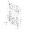
内枠2の遊技盤収納部5には、図2に示すように、遊技盤ユニット20が着脱可能に収納されている。この遊技盤ユニット20は、図3に示すように、遊技盤30と裏樋60と液晶ステー90と下意匠板100と上意匠板110と裏樋カバー120と表示器ケース130と装飾図柄表示器140を有するものであり、遊技盤30〜装飾図柄表示器140の詳細構成は次の通りである。
1.遊技盤30の説明
遊技盤30は透明な合成樹脂(例えばポリカーボネートあるいはアクリルあるいはアクリルにゴムを混ぜた材質)の板からなるものであり、遊技盤30の前面には、図4に示すように、外レール31および内レール32が固定されている。これら外レール31と内レール32との間には発射通路33が形成されている。この発射通路33は遊技盤30の左端部に位置する円弧状の空間部を称するものであり、発射装置15が発射した遊技球は発射レールから発射通路33内に発射通路33の入口34から侵入し、発射通路33に沿って円弧状の軌跡を描きながら上昇した後に発射通路33の出口35から放出される。
As shown in FIG. 2, the game board unit 20 is detachably stored in the game board storage part 5 of the inner frame 2. As shown in FIG. 3, the game board unit 20 includes a game board 30, a back wall 60, a liquid crystal stay 90, a lower design board 100, an upper design board 110, a back cover 120, a display case 130, and a decorative design display. The detailed configuration of the game board 30 to the decorative symbol display 140 is as follows.
1. Description of the Game Board 30 The game board 30 is made of a transparent synthetic resin (for example, polycarbonate, acrylic, or a material in which acrylic is mixed with rubber), and on the front surface of the game board 30, as shown in FIG. The outer rail 31 and the inner rail 32 are fixed. A firing passage 33 is formed between the outer rail 31 and the inner rail 32. This launch passage 33 refers to an arcuate space located at the left end of the game board 30, and the game ball launched by the launch device 15 enters the launch passage 33 from the launch rail through the entrance 34 of the launch passage 33. Then, after rising while drawing an arcuate trajectory along the launch passage 33, it is discharged from the outlet 35 of the launch passage 33.

遊技盤30の前面には右上部に位置して合成樹脂製の球止め部材36が固定されている。この球止め部材36は外レール31の右端部と内レール32の右端部との間の隙間を埋めるものであり、球止め部材36と外レール31と内レール32との間には遊技領域37が形成されている。この遊技領域37は外レール31と内レール32と球止め部材36によって囲まれた領域のうち発射通路33を除く円形状をなすものである。この遊技領域37は発射通路33の出口35から放出された遊技球が転動可能な最大範囲である転動領域に相当するものであり、遊技領域37内には複数の釘38が固定されている。   A ball stop member 36 made of synthetic resin is fixed to the front surface of the game board 30 at the upper right part. This ball stopper member 36 fills a gap between the right end portion of the outer rail 31 and the right end portion of the inner rail 32, and a game area 37 is provided between the ball stopper member 36, the outer rail 31 and the inner rail 32. Is formed. The game area 37 has a circular shape excluding the launch passage 33 in the area surrounded by the outer rail 31, the inner rail 32, and the ball stopper 36. The game area 37 corresponds to a rolling area that is the maximum range in which the game ball released from the outlet 35 of the launch passage 33 can roll, and a plurality of nails 38 are fixed in the game area 37. Yes.

遊技盤30の前面には飾りレール39が固定されている。この飾りレール39は遊技領域37内に配置されたものであり、飾りレール39と外レール31との間には球通路40が形成され、飾りレール39と内レール32との間には球通路41が形成されている。これら球通路40および球通路41のそれぞれは遊技領域37内に放出された遊技球が転動可能なものであり、上方の球通路40は左方の球通路41に比べて幅狭に設定されている。遊技盤30の前面には遊技領域37の外部に位置して銘板台53が固定されている。この銘板台53の前面にはシールが貼付されており、シールには機種名・製造社名・大当り確率・賞品球の払出し個数が記入されている。   A decorative rail 39 is fixed to the front surface of the game board 30. The decoration rail 39 is arranged in the game area 37, a ball passage 40 is formed between the decoration rail 39 and the outer rail 31, and a ball passage is formed between the decoration rail 39 and the inner rail 32. 41 is formed. Each of the ball passage 40 and the ball passage 41 is configured such that the game ball released into the game area 37 can roll, and the upper ball passage 40 is set narrower than the left ball passage 41. ing. On the front surface of the game board 30, a nameplate base 53 is fixed outside the game area 37. A sticker is affixed to the front surface of the nameplate base 53, and the model name, manufacturer name, jackpot probability, and the number of prize balls to be paid out are written on the sticker.

遊技盤30には遊技領域37内に位置して電動始動装置42が固定されている。この電動始動装置42は上始動口43および下始動口44を上下2段に有するものであり、上始動口43および下始動口44のそれぞれは上面が開口するポケット状をなしている。これら上始動口43内および下始動口44内のそれぞれには始動口センサが装着されており、上始動口43内の始動口センサは遊技球が上始動口43内に入賞したことを検出して制御基板に始動信号を出力し、下始動口44内の始動口センサは遊技球が下始動口44内に入賞したことを検出して制御基板に始動信号を出力する。この制御基板は内枠2に固定されたものであり、始動信号を検出することに基づいて上皿13内に設定個数の遊技球を賞品球として払出し、大当りおよび外れを判定する。   An electric starter 42 is fixed to the game board 30 in the game area 37. The electric starter 42 has an upper starter port 43 and a lower starter port 44 in two upper and lower stages, and each of the upper starter port 43 and the lower starter port 44 has a pocket shape whose upper surface is opened. Each of the upper start opening 43 and the lower start opening 44 is provided with a start opening sensor, and the start opening sensor in the upper start opening 43 detects that a game ball has won the upper start opening 43. The start signal is output to the control board, and the start opening sensor in the lower start opening 44 detects that the game ball has won the lower start opening 44 and outputs the start signal to the control board. This control board is fixed to the inner frame 2, and based on the detection of the start signal, a predetermined number of game balls are paid out as prize balls in the upper plate 13, and the big hit and miss are determined.

下始動口44には2枚の羽根板45が装着されており、両羽根板45は共通の始動口ソレノイドに連結されている。これら両羽根板45は始動口ソレノイドが断電されることに基づいて垂直な縮小状態になるものであり、図4は両羽根板45を縮小状態で示している。これら両羽根板45の縮小状態では両羽根板45相互間の隙間が上始動口43によって上方から閉鎖され、遊技球が上始動口43内のみに入賞することが許容される。これら両羽根板45は始動口ソレノイドが通電されることに基づいて水平な拡大状態に回動するものであり、両羽根板45の拡大状態では下始動口44の左右両側部を落下する遊技球が羽根板45によって捕捉されることに基づいて下始動口44内に入賞可能になる。   Two blades 45 are mounted on the lower start port 44, and both blade plates 45 are connected to a common start port solenoid. These blades 45 are in a vertically reduced state based on the start-up solenoid being de-energized, and FIG. 4 shows both blades 45 in a reduced state. In the contracted state of these two blades 45, the gap between the two blades 45 is closed from above by the upper start opening 43, and the game ball is allowed to win only in the upper start opening 43. Both the blades 45 are rotated in a horizontally expanded state based on energization of the start opening solenoids, and in the expanded state of the both blades 45, the game balls fall on both the left and right side portions of the lower start opening 44. Can be won in the lower start port 44 based on the fact that the is captured by the blade 45.

遊技盤30には遊技領域37内に位置して特別電動入賞装置46が固定されている。この特別電動入賞装置46は前面が開放する特別入賞口および扉47を有するものであり、扉47は特別入賞口ソレノイドに連結されている。この扉47は特別入賞口ソレノイドの断電状態で垂直な閉鎖状態になることに基づいて特別入賞口の前面を遊技球が入賞不能に閉鎖するものであり、図4は扉47を閉鎖状態で示している。この扉47は特別入賞口ソレノイドの通電状態で前方へ水平に倒れた開放状態に回動するものであり、扉47の開放状態では遊技球が扉47に乗って特別入賞口内に転がり込むことが許容される。この特別入賞口内にはカウントセンサが装着されており、カウントセンサは遊技球が特別入賞口内に入賞したことを検出して制御基板にカウント信号を出力し、制御基板はカウント信号を検出することに基づいて上皿13内に設定個数の遊技球を賞品球として払出す。   A special electric prize winning device 46 is fixed to the game board 30 in the game area 37. This special electric prize-winning device 46 has a special prize-winning opening and a door 47 whose front face is open, and the door 47 is connected to a special prize-winning solenoid. This door 47 closes the front of the special winning opening in a non-winning state based on the fact that the special winning opening solenoid is in a vertically closed state when the power is cut off, and FIG. 4 shows that the door 47 is closed. Show. The door 47 is rotated to the open state in which the special prize opening solenoid is energized to the front, and the door 47 is opened to allow the game ball to ride on the door 47 and roll into the special prize opening. Is done. A count sensor is mounted in the special prize opening. The count sensor detects that a game ball has won the special prize opening and outputs a count signal to the control board. The control board detects the count signal. Based on this, a predetermined number of game balls are paid out into the upper plate 13 as prize balls.

遊技盤30には、図3に示すように、始動口取付孔48および特別入賞口取付孔49が形成されており、始動口取付孔48内には電動始動装置42の樋50が挿入され、特別入賞口取付孔49内には特別電動入賞装置46の樋51が挿入されている。樋50は電動始動装置42の上始動口43および下始動口44の双方に接続されたものであり、上始動口43内に入賞した遊技球および下始動口44内に入賞した遊技球はいずれも樋50に沿って後方へ転がる。樋51は特別電動入賞装置46の特別入賞口に接続されたものであり、特別入賞口内に入賞した遊技球は樋51に沿って後方へ転がる。遊技盤30には特別入賞口取付孔49の下方に位置してアウト孔52が形成されている。このアウト孔52は、図4に示すように、内レール32の最低部に配置されたものであり、上始動口43と下始動口44と特別入賞口のいずれにも入賞しなかった遊技球は内レール34に沿ってアウト孔52内に転がり込む。
2.裏樋60の説明
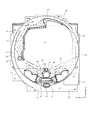
裏樋60は、図3に示すように、下部裏樋61と左部裏樋62と右部裏樋63と上部裏樋64の4部材を有するものであり、下部裏樋61は後方から下部裏樋61を通して遊技盤30に複数のネジを螺合することで遊技盤30の後面に直接的に接合され、左部裏樋62は後方から左部裏樋62を通して遊技盤30に複数のネジを螺合することで遊技盤30の後面に直接的に接合され、上部裏樋64は後方から上部裏樋64を通して遊技盤30に複数のネジを螺合することで遊技盤30の後面に直接的に接合されている。
As shown in FIG. 3, the game board 30 is formed with a start port mounting hole 48 and a special prize port mounting hole 49, and the rod 50 of the electric starter 42 is inserted into the start port mounting hole 48, In the special prize opening mounting hole 49, the collar 51 of the special electric prize-winning device 46 is inserted. The kite 50 is connected to both the upper start opening 43 and the lower start opening 44 of the electric starter 42. Which of the game balls won in the upper start opening 43 and the game ball won in the lower start opening 44? Also rolls back along the ridge 50. The bowl 51 is connected to the special prize opening of the special electric prize-winning device 46, and the game ball won in the special prize opening rolls backward along the bowl 51. An out hole 52 is formed in the game board 30 so as to be positioned below the special prize opening mounting hole 49. As shown in FIG. 4, the out hole 52 is disposed at the lowest part of the inner rail 32, and a game ball that has not won any of the upper start opening 43, the lower start opening 44, or the special winning opening. Rolls into the out hole 52 along the inner rail 34.
2. 3. Description of Back Coffin 60 As shown in FIG. 3, the back coffin 60 has four members, ie, a lower back coffin 61, a left side coffin 62, a right side coffin 63, and an upper back coffin 64. 61 is directly joined to the rear surface of the game board 30 by screwing a plurality of screws into the game board 30 through the lower back wall 61 from the rear, and the left side wall 62 is passed through the left back wall 62 from the back. A plurality of screws are screwed to 30 to be directly joined to the rear surface of the game board 30, and the upper back bowl 64 is screwed to the game board 30 from the rear through the upper back bowl 64 to play the game board 30. It is joined directly to the rear surface of 30.

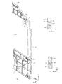
上部裏樋64の右端部には、図5に示すように、突状の継手部65が形成されており、上部裏樋64の継手部65は右部裏樋63の継手部66に後方から重ねられている。この継手部66は厚さ寸法が右部裏樋63の残り部分に比べて薄く設定されたものであり、継手部65および継手部66の双方には前後方向へ延びる軸67が挿入され、右部裏樋63は軸67を中心に下部裏樋61と左部裏樋62と上部裏樋64の3部材に対して回動可能にされている。   As shown in FIG. 5, a protruding joint 65 is formed at the right end of the upper case 64, and the joint 65 of the upper case 64 is connected to the joint 66 of the right case 63 from behind. It is piled up. The joint portion 66 has a thickness set to be thinner than that of the remaining portion of the right side collar 63, and a shaft 67 extending in the front-rear direction is inserted into both the joint portion 65 and the joint portion 66. The back cover 63 is rotatable with respect to three members of a lower back cover 61, a left back cover 62, and an upper back cover 64 around a shaft 67.

右部裏樋63は清掃口68を開放状態および閉鎖状態に相互に切換える開閉部材に相当するものである。この清掃口68は、図6に示すように、下部裏樋61および上部裏樋64相互間の右端部に形成された空間部を称するものであり、図5に示すように、右部裏樋63が垂直な閉鎖状態に回動操作されることに基づいて閉鎖され、図6に示すように、右部裏樋63が水平な開放状態に回動操作されることに基づいて開放される。   The right rear casing 63 corresponds to an opening / closing member that switches the cleaning port 68 between an open state and a closed state. As shown in FIG. 6, the cleaning port 68 refers to a space formed at the right end between the lower case 61 and the upper case 64, and as shown in FIG. 63 is closed based on the pivoting operation in the vertical closed state, and as shown in FIG. 6, the right side ridge 63 is opened based on the pivoting operation in the horizontal open state.

右部裏樋63の下端部には、図5に示すように、抜止め突部69が形成されており、抜止め突部69は右部裏樋63が閉鎖状態に回動操作されることに基づいて抜止め溝部70内に係合する。この抜止め溝部70は下部裏樋61に形成されたものであり、抜止め突部69は、図6に示すように、右部裏樋63が開放状態に回動操作されることに基づいて抜止め溝部70内から脱出する。即ち、抜止め突部69は抜止め溝部70に対して着脱可能にされたものである。   As shown in FIG. 5, a retaining projection 69 is formed at the lower end of the right rear casing 63, and the retaining projection 69 is operated to rotate the right rear casing 63 in the closed state. Is engaged in the retaining groove 70. The retaining groove 70 is formed in the lower case 61, and the retaining projection 69 is based on the right side member 63 being rotated to the open state as shown in FIG. Escape from the retaining groove 70. That is, the retaining protrusion 69 is detachable from the retaining groove 70.

右部裏樋63の右側面にはロック片71の上端部が着脱不能に固定されており、ロック片71の下端部には、図6に示すように、貫通孔72が形成されている。この貫通孔72内には、図5に示すように、ネジ73が挿入されており、ネジ73はネジ孔74内に螺合されている。このネジ孔74は、図6に示すように、下部裏樋61の右側面に形成されたものであり、右部裏樋63はネジ73およびネジ孔74間の係合力で閉鎖状態にロックされている。このネジ73がネジ孔74から取外されたときには右部裏樋63のロックが解除され、右部裏樋63を閉鎖状態から開放状態に回動操作することが可能になる。このロック片71が右部裏樋63を閉鎖状態にロックする状態をロック状態と称し、ロック片71が右部裏樋63のロックを解除する状態をアンロック状態と称する。   The upper end portion of the lock piece 71 is fixed to the right side surface of the right rear case 63 so as not to be detachable, and a through hole 72 is formed in the lower end portion of the lock piece 71 as shown in FIG. As shown in FIG. 5, a screw 73 is inserted into the through hole 72, and the screw 73 is screwed into the screw hole 74. As shown in FIG. 6, the screw hole 74 is formed on the right side surface of the lower lining 61, and the right lining 63 is locked in a closed state by the engagement force between the screw 73 and the screw hole 74. ing. When the screw 73 is removed from the screw hole 74, the lock of the right side case 63 is released, and the right side case 63 can be rotated from the closed state to the open state. A state in which the lock piece 71 locks the right rear case 63 in the closed state is referred to as a locked state, and a state in which the lock piece 71 unlocks the right side case 63 is referred to as an unlocked state.

下部裏樋61には、図3に示すように、始動口挿入孔75および特別入賞口挿入孔76が形成されており、電動始動装置42の樋50は始動口挿入孔75内に挿入され、特別電動入賞装置46の樋51は特別入賞口挿入孔76内に挿入されている。この下部裏樋61にはアウト口77が形成されている。このアウト口77は前後面が開口する筒状をなすものであり、遊技盤30のアウト孔52の内周面に嵌合されている。   As shown in FIG. 3, a starting port insertion hole 75 and a special winning port insertion hole 76 are formed in the lower back rod 61, and the rod 50 of the electric starter 42 is inserted into the starting port insertion hole 75, The spear 51 of the special electric winning device 46 is inserted into the special winning opening insertion hole 76. An out port 77 is formed in the lower lining 61. The out port 77 has a cylindrical shape whose front and rear surfaces are open, and is fitted to the inner peripheral surface of the out hole 52 of the game board 30.

下部裏樋61には左下厚さ調整部78および右下厚さ調整部79が形成されている。これら左下厚さ調整部78および右下厚さ調整部79のそれぞれは遊技盤30の前後方向の厚さ寸法を厚く調整するものであり、左下厚さ調整部78は遊技盤30と共に左下の支え部6および左下のストッパ9相互間で挟持され、右下厚さ調整部79は遊技盤30と共に右下の支え部6および右下のストッパ9相互間で挟持される。上部裏樋64には左上厚さ調整部80および右上厚さ調整部81が形成されている。これら左上厚さ調整部80および右上厚さ調整部81のそれぞれは遊技盤30の前後方向の厚さ寸法を厚く調整するものであり、左上厚さ調整部80は遊技盤30と共に左上の支え部6および左上のストッパ7相互間で挟持され、右上厚さ調整部81は遊技盤30と共に右上の支え部6および右上のストッパ7相互間で挟持される。
3.液晶ステー90の詳細構成
液晶ステー90は、図3に示すように、下部ステー91と左部ステー92と右部ステー93と上部ステー94を有する矩形枠状をなすものであり、下部ステー91と左部ステー92と右部ステー93と上部ステー94は単一物として一体成形されている。この液晶ステー90は後方から液晶ステー90を通して下部裏樋61と左部裏樋62と上部裏樋64の3部材にネジを螺合することで3部材の後面に直接的に接合されたものであり、裏樋60と共にスペーサ150(図2参照)を構成している。このスペーサ150は枠部材に相当するものであり、図3に示すように、下横部151と左縦部152と右縦部153と上横部154を有している。下横部151は下部裏樋61および下部ステー91から構成されたものであり、左縦部152は左部裏樋62および左部ステー92から構成されたものであり、右縦部153は右部裏樋63および右部ステー93から構成されたものであり、上横部154は上部裏樋64および上部ステー94から構成されたものである。
3.下意匠板100の説明
下意匠板100は前方から下意匠板100を通して下部裏樋61に複数のネジを螺合することで下部裏樋61の前面に直接的に接合されたものであり、遊技盤30と下部裏樋61との間に配置されている。この下意匠板100の前面には絵柄が印刷されており、下意匠板100の絵柄は前方から遊技盤30を通して視覚的に認識可能にされている。この下意匠板100には始動口挿入孔101と特別入賞口挿入孔102と切欠部103が形成されており、電動始動装置42の樋50は始動口挿入孔101内を通して下部裏樋61の始動口挿入孔75内に挿入され、特別電動入賞装置46の樋51は特別入賞口挿入孔102内を通して下部裏樋61の特別入賞口挿入孔76内に挿入され、下部裏樋61のアウト口77は切欠部103を通して遊技盤30のアウト孔52内に嵌合されている。
4.上意匠板110の説明
上意匠板110は前方から上意匠板110を通して上部裏樋64に複数のネジを螺合することで上部裏樋64の前面に直接的に接合されたものであり、遊技盤30と上部裏樋64との間に配置されている。この上意匠板110の前面には絵柄が印刷されており、上意匠板110の絵柄は前方から遊技盤30を通して視覚的に認識可能にされている。
5.裏樋カバー120の説明
裏樋カバー120は後方から裏樋カバー120を通して下部裏樋61に複数のネジを螺合することで下部裏樋61の後面に直接的に接合されたものであり、裏樋カバー120には球排出路が形成されている。この球排出路は電動始動装置42の樋50から落下した遊技球および特別電動入賞装置46の樋51から落下した遊技球が侵入するものであり、樋50から落下した遊技球および樋51から落下した遊技球は球排出路を通して裏樋カバー120の外部に排出される。
6.表示器ケース130の説明
表示器ケース130は下板部131と左板部132と右板部133と上板部134と後板部135を有する矩形皿状をなすものであり、下板部131と左板部132と右板部133と上板部134と後板部135の間には空間状の表示器収納部136が形成されている。この表示器ケース130の下板部131には2枚の下プレート137が形成され、表示器ケース130の上板部134には1枚の上プレート138が形成されており、各下プレート137には後方から複数のネジが挿入され、上プレート138には後方から複数のネジが挿入されている。各下プレート137に挿入された複数のネジは下部裏樋61に螺合され、上プレート138に挿入された複数のネジは上部裏樋64に螺合されており、表示器ケース130は裏樋60を介して遊技盤30の後面に間接的に接合され、液晶ステー90は表示器ケース130の表示器収納部136内に収納されている。
7.装飾図柄表示器140の説明
装飾図柄表示器140は表示器ケース130の表示器収納部136内に収納されたものであり、液晶画面141および液晶画面141を保持する矩形状の画面フレーム142を有している。この画面フレーム142は液晶ステー90と表示器ケース130の後板部135との間で挟持されたものであり、装飾図柄表示器140は遊技盤30に裏樋60および液晶ステー90を介して間接的に接合されている。この装飾図柄表示器140の画面フレーム142には外部から表示器ケース130を通して複数のネジが螺合されており、装飾図柄表示器140は複数のネジを介して表示器ケース130に固定されている。この装飾図柄表示器140と遊技盤30と裏樋60と液晶ステー90の間には、図5に示すように、閉鎖空間160が形成されている。この閉鎖空間160は遊技盤30と裏樋60と液晶ステー90と装飾図柄表示器140で囲まれた空間部を称するものであり、清掃口68は、図6に示すように、閉鎖空間160の外部から内部に清掃具161を挿入する開口部として機能する。この清掃具161は遊技盤30の後面に付着した埃および装飾図柄表示器140の液晶画面141に付着した埃を払拭するものであり、柄162の先端部にスポンジ163を固定することから構成されている。
A lower left thickness adjusting portion 78 and a lower right thickness adjusting portion 79 are formed on the lower case 61. Each of the lower left thickness adjustment unit 78 and the lower right thickness adjustment unit 79 adjusts the thickness dimension in the front-rear direction of the game board 30, and the lower left thickness adjustment part 78 supports the lower left with the game board 30. The lower right thickness adjusting portion 79 is sandwiched between the lower right support portion 6 and the lower right stopper 9 together with the game board 30. An upper left thickness adjusting portion 80 and an upper right thickness adjusting portion 81 are formed on the upper case 64. Each of the upper left thickness adjustment unit 80 and the upper right thickness adjustment unit 81 adjusts the thickness dimension in the front-rear direction of the game board 30, and the upper left thickness adjustment part 80 is connected to the upper left support part together with the game board 30. 6 and the upper left stopper 7 are sandwiched between the upper right thickness adjusting portion 81 together with the game board 30 between the upper right support portion 6 and the upper right stopper 7.
3. Detailed Configuration of Liquid Crystal Stay 90 As shown in FIG. 3, the liquid crystal stay 90 has a rectangular frame shape having a lower stay 91, a left stay 92, a right stay 93, and an upper stay 94. The left stay 92, the right stay 93, and the upper stay 94 are integrally formed as a single object. The liquid crystal stay 90 is directly joined to the rear surface of the three members by screwing screws into the three members of the lower back cover 61, the left back cover 62, and the upper back cover 64 from the rear through the liquid crystal stay 90. The spacer 150 (refer to FIG. 2) is configured together with the back cover 60. The spacer 150 corresponds to a frame member and has a lower horizontal portion 151, a left vertical portion 152, a right vertical portion 153, and an upper horizontal portion 154 as shown in FIG. The lower horizontal portion 151 is composed of a lower case 61 and a lower stay 91, the left vertical portion 152 is composed of a left portion 62 and a left stay 92, and the right vertical portion 153 is a right portion. The upper lateral portion 154 is composed of the upper back collar 64 and the upper stay 94.
3. Description of the lower design board 100 The lower design board 100 is directly joined to the front surface of the lower case 61 by screwing a plurality of screws into the lower case 61 through the lower design board 100 from the front. It is arranged between the board 30 and the lower lining 61. A picture is printed on the front surface of the lower design board 100, and the picture of the lower design board 100 can be visually recognized through the game board 30 from the front. The lower design plate 100 is formed with a start opening insertion hole 101, a special prize opening insertion hole 102 and a notch 103, and the rod 50 of the electric starter 42 passes through the start opening insertion hole 101 to start the lower back rod 61. The rod 51 of the special electric prize-winning device 46 is inserted into the mouth insertion hole 75 and is inserted into the special prize opening insertion hole 76 of the lower case 61 through the special prize opening insertion hole 102, and the out port 77 of the lower case 61. Is fitted into the out hole 52 of the game board 30 through the notch 103.
4). Description of the upper design board 110 The upper design board 110 is directly joined to the front surface of the upper back cover 64 by screwing a plurality of screws into the upper back cover 64 from the front through the upper design board 110. It is arranged between the board 30 and the upper lining 64. A picture is printed on the front surface of the upper design board 110, and the picture of the upper design board 110 can be visually recognized through the game board 30 from the front.
5). Description of the back cover 120 The back cover 120 is directly joined to the rear surface of the lower back 61 by screwing a plurality of screws into the lower back 61 through the back cover 120 from the rear. A ball discharge path is formed in the heel cover 120. This ball discharge path is where game balls that have fallen from the cage 50 of the electric starter 42 and game balls that have fallen from the cage 51 of the special electric prize-winning device 46 enter. The played game balls are discharged to the outside of the back cover 120 through the ball discharge path.
6). Description of Display Case 130 The display case 130 has a rectangular dish shape having a lower plate portion 131, a left plate portion 132, a right plate portion 133, an upper plate portion 134, and a rear plate portion 135, and the lower plate portion 131. Between the left plate portion 132, the right plate portion 133, the upper plate portion 134, and the rear plate portion 135, a spatial display housing portion 136 is formed. Two lower plates 137 are formed on the lower plate portion 131 of the display case 130, and one upper plate 138 is formed on the upper plate portion 134 of the display case 130. A plurality of screws are inserted from the rear, and a plurality of screws are inserted into the upper plate 138 from the rear. The plurality of screws inserted into each lower plate 137 are screwed into the lower case 61, the plurality of screws inserted into the upper plate 138 are screwed into the upper case 64, and the display case 130 is The liquid crystal stay 90 is indirectly joined to the rear surface of the game board 30 via 60, and is housed in the display housing portion 136 of the display case 130.
7). Description of Decorative Symbol Display 140 The decorative symbol display 140 is housed in the display housing portion 136 of the display case 130 and has a liquid crystal screen 141 and a rectangular screen frame 142 that holds the liquid crystal screen 141. is doing. The screen frame 142 is sandwiched between the liquid crystal stay 90 and the rear plate portion 135 of the display case 130, and the decorative symbol display 140 is indirectly connected to the game board 30 via the back wall 60 and the liquid crystal stay 90. Are joined together. A plurality of screws are screwed into the screen frame 142 of the decorative design indicator 140 from the outside through the display case 130, and the decorative design indicator 140 is fixed to the display case 130 via the plurality of screws. . As shown in FIG. 5, a closed space 160 is formed between the decorative symbol display 140, the game board 30, the back wall 60, and the liquid crystal stay 90. The closed space 160 refers to a space surrounded by the game board 30, the back wall 60, the liquid crystal stay 90, and the decorative symbol display 140, and the cleaning port 68 is formed in the closed space 160 as shown in FIG. 6. It functions as an opening for inserting the cleaning tool 161 from the outside to the inside. This cleaning tool 161 wipes off dust adhering to the rear surface of the game board 30 and dust adhering to the liquid crystal screen 141 of the decorative symbol display 140, and is configured by fixing a sponge 163 to the tip of the handle 162. ing.

装飾図柄表示器140の液晶画面141は下部裏樋61と左部裏樋62と右部裏樋63と上部裏樋64で囲まれた内部空間および下部ステー91と左部ステー92と右部ステー93と上部ステー94で囲まれた内部空間の後方に配置されており、下部裏樋61および下部ステー91のそれぞれは液晶画面141の下端面に沿って横方向へ延び、左部裏樋62および左部ステー92のそれぞれは液晶画面141の左側面に沿って縦方向へ延び、右部裏樋63および右部ステー93のそれぞれは液晶画面141の右側面に沿って縦方向へ延び、上部裏樋64および上部ステー94のそれぞれは液晶画面141の上端面に沿って横方向へ延びている。この液晶画面141は表示画面に相当するものであり、前方から遊技盤30と裏樋60の内部空間と液晶ステー90の内部空間を通して全体が視覚的に認識可能にされている。この液晶画面141は装飾図柄が表示されるものである。この装飾図柄は大当りおよび外れを識別する識別図柄として機能するものであり、左列の図柄要素と中列の図柄要素と右列の図柄要素から構成されている。
8.遊技盤ユニット20の装着状態について
遊技盤ユニット20は上皿板12および窓枠17の双方が開放された状態で前方から内枠2の遊技盤収納部5内に収納されるものである。この遊技盤ユニット20の収納状態では裏樋60の左下厚さ調整部78と右下厚さ調整部79と左上厚さ調整部80と右上厚さ調整部81のそれぞれが内枠2の支え部6によって後方から支えられ、左下厚さ調整部78が遊技盤30と共に前方のストッパ9と後方の支え部6との間で挟持され、右下厚さ調整部79が遊技盤30と共に前方のストッパ9と後方の支え部6との間で挟持されており、残りの各ストッパ7が遊技盤30に前方から重なるロック状態に回動操作されたときには左上厚さ調整部80が遊技盤30と共に前方のストッパ7と後方の支え部6との間で挟持され、右上厚さ調整部81が遊技盤30と共に前方のストッパ7と後方の支え部6との間で挟持される。遊技盤ユニット20は上皿板12および窓枠17の双方が開放された状態で内枠2の遊技盤収納部5内から取外されるものである。この場合には両ストッパ7を遊技盤30の前方から外れるアンロック状態に回動操作し、左上厚さ調整部80と右上厚さ調整部81のそれぞれを遊技盤30と共に挟持解除状態にする。
9.遊技盤ユニット20のメンテナンスについて
遊技盤30の後面に埃が付着したり、あるいは、装飾図柄表示器140の液晶画面141に埃が付着したときには内枠2を閉鎖状態から開放状態に軸3を中心に回動操作する。この内枠2の開放状態では右部裏樋63およびロック片71が前方から操作可能な露出状態になるので、ロック片71のネジ73を取外すことに基づいて右部裏樋63のロックを解除する。そして、右部裏樋63を閉鎖状態から開放状態に回動操作し、清掃口68を開放する。この清掃口68の開放状態で右方から清掃口68を通して閉鎖空間160の内部に清掃具161を挿入し、遊技盤30の後面および装飾図柄表示器140の液晶画面141を清掃具161のスポンジ163で払拭する。次に右部裏樋63を開放状態から閉鎖状態に回動操作し、清掃口68を閉鎖する。この右部裏樋63の閉鎖状態でロック片71を通して右部裏樋63のネジ孔74にネジ73を螺合し、右部裏樋63を閉鎖状態にロックした後で内枠2を開放状態から閉鎖状態に戻す。
10.遊技機能の説明
装飾図柄表示器140の液晶画面141には、図7の(a)に示すように、左列の図柄要素と中列の図柄要素と右列の図柄要素のそれぞれとして「1」「2」「3」「4」「5」「6」「7」「8」のいずれかの数字が変動停止状態で表示されており、遊技球が電動始動装置42の上始動口43内および下始動口44内のいずれかに入賞したときには、図7の(b)に示すように、3列の図柄要素が変動停止状態から変動状態になる。この変動状態とは縦一列に並ぶ「1」〜「8」の8種の図柄要素を縦方向に表示範囲が移動するようにスクロール表示するものであり、各列の図柄要素は上から下へ移動しながら「1」→「2」→「3」→「4」→「5」→「6」→「7」→「8」→「1」…の順序で循環的に変化する。これら左列の図柄要素と中列の図柄要素と右列の図柄要素は装飾図柄を構成するものであり、装飾図柄は(1)左列の図柄要素(2)右列の図柄要素(3)中列の図柄要素の順序で変動停止する。
The liquid crystal screen 141 of the decorative symbol display 140 has an inner space surrounded by a lower case 61, a left case 62, a right case 63, and an upper case 64, a lower stay 91, a left stay 92, and a right stay. 93 and the upper stay 94 are disposed behind the inner space, and each of the lower lining 61 and the lower stay 91 extends laterally along the lower end surface of the liquid crystal screen 141, and the left lining 62 and Each of the left part stays 92 extends in the vertical direction along the left side surface of the liquid crystal screen 141, and each of the right side wall 63 and the right part stay 93 extends in the vertical direction along the right side surface of the liquid crystal screen 141, and Each of the collar 64 and the upper stay 94 extends in the lateral direction along the upper end surface of the liquid crystal screen 141. The liquid crystal screen 141 corresponds to a display screen, and is visually recognizable through the internal space of the game board 30 and the back wall 60 and the internal space of the liquid crystal stay 90 from the front. The liquid crystal screen 141 displays a decorative pattern. This decorative symbol functions as an identification symbol for identifying a big hit or miss and is composed of a symbol element in the left column, a symbol element in the middle column, and a symbol element in the right column.
8). About the mounted state of the game board unit 20 The game board unit 20 is stored in the game board storage part 5 of the inner frame 2 from the front with both the upper plate 12 and the window frame 17 opened. In the stored state of the game board unit 20, the lower left thickness adjusting portion 78, the lower right thickness adjusting portion 79, the upper left thickness adjusting portion 80, and the upper right thickness adjusting portion 81 of the back cage 60 are respectively the support portions of the inner frame 2. 6, the lower left thickness adjusting portion 78 is sandwiched between the front stopper 9 and the rear supporting portion 6 together with the game board 30, and the lower right thickness adjusting portion 79 together with the game board 30 is the front stopper. 9 and the rear support portion 6, and when the remaining stoppers 7 are turned to the locked state overlapping the game board 30 from the front, the upper left thickness adjustment section 80 moves forward together with the game board 30. The upper right thickness adjustment portion 81 is sandwiched between the front stopper 7 and the rear support portion 6 together with the game board 30. The game board unit 20 is removed from the game board storage part 5 of the inner frame 2 in a state where both the upper plate 12 and the window frame 17 are opened. In this case, both stoppers 7 are turned to an unlocked state where the stoppers 7 are disengaged from the front of the game board 30, and the upper left thickness adjusting part 80 and the upper right thickness adjusting part 81 are brought into the nipping release state together with the game board 30.
9. Maintenance of the game board unit 20 When dust adheres to the rear surface of the game board 30 or dust adheres to the liquid crystal screen 141 of the decorative symbol display 140, the inner frame 2 is centered from the closed state to the open state. To rotate. When the inner frame 2 is in the open state, the right rear case 63 and the lock piece 71 are exposed so that they can be operated from the front, and the right side case 63 is unlocked by removing the screw 73 of the lock piece 71. To do. Then, the right rear casing 63 is rotated from the closed state to the opened state, and the cleaning port 68 is opened. With the cleaning port 68 open, the cleaning tool 161 is inserted into the closed space 160 from the right through the cleaning port 68, and the rear surface of the game board 30 and the liquid crystal screen 141 of the decorative symbol display 140 are connected to the sponge 163 of the cleaning tool 161. Wipe with. Next, the right rear ridge 63 is rotated from the open state to the closed state, and the cleaning port 68 is closed. In the closed state of the right side hook 63, the screw 73 is screwed into the screw hole 74 of the right side hook 63 through the lock piece 71, and the inner frame 2 is opened after the right side hook 63 is locked in the closed state. Return to the closed state.
10. Explanation of Game Functions As shown in FIG. 7A, the liquid crystal screen 141 of the decorative symbol display 140 has “1” as a symbol element in the left column, a symbol element in the middle column, and a symbol element in the right column. Any number of “2”, “3”, “4”, “5”, “6”, “7”, and “8” is displayed in a variable stop state, and the game ball is placed in the upper start port 43 of the electric starter 42 and When winning in any of the lower start ports 44, as shown in FIG. 7B, the three rows of symbol elements change from the variable stop state to the variable state. In this variation state, eight types of symbol elements “1” to “8” arranged in a vertical row are scroll-displayed so that the display range moves in the vertical direction, and the symbol elements in each column are from top to bottom. While moving, it changes cyclically in the order of “1” → “2” → “3” → “4” → “5” → “6” → “7” → “8” → “1”. These symbol elements in the left column, the symbol elements in the middle column, and the symbol elements in the right column constitute a decorative symbol. The decorative symbols are (1) symbol elements in the left column (2) symbol elements in the right column (3) Fluctuation stops in the order of symbol elements in the middle row.

左列の図柄要素および右列の図柄要素の両者が変動停止した状態でリーチの組合せになったときには複数種の演出映像が選択的に表示される。このリーチの組合せとは、図7の(c)に示すように、左列の図柄要素および右列の図柄要素が相互に同一な組合せを称するものであり、演出映像とは最終の中列の図柄要素が左列の図柄要素および右列の図柄要素と同一の数字で変動停止するか否かを演出する物語調の映像を称する。図7の(d)〜(f)は演出映像の一例を示すものであり、殿が風呂の熱さに耐えられるか否かで中列の図柄要素が左列の図柄要素および右列の図柄要素と同一の数字で変動停止するか否かが演出される。   When both the symbol elements in the left column and the symbol elements in the right column are variably stopped, a combination of reach is selectively displayed. As shown in FIG. 7 (c), this reach combination refers to a combination in which the symbol elements in the left column and the symbol elements in the right column are identical to each other. This refers to a narrative-like video that directs whether or not the symbol elements stop changing at the same numbers as the symbol elements in the left column and the right column. (D) to (f) of FIG. 7 show examples of effect images, and depending on whether the shrine can withstand the heat of the bath, the symbol elements in the middle row are the symbol elements in the left column and the symbol elements in the right column. Whether or not the change is stopped is produced with the same number.

左列の図柄要素と右列の図柄要素と中列の図柄要素の全てが変動停止した状態で大当りの組合せになったときには大当り遊技が開始され、大当りの組合せとは相違する外れの組合せになったときには大当り遊技が開始されない。大当りの組合せは左列の図柄要素と中列の図柄要素と右列の図柄要素が相互に同一な組合せを称するものであり、大当りの組合せには「111」「222」「333」「444」「555」「666」「777」「888」の8通りが設定されている。大当り遊技は特別電動入賞装置46の扉47を開放し、特別電動入賞装置46の特別入賞口内に遊技球が入賞することを許容する遊技者有利の状態を発生させるものであり、扉47は特別入賞口内に上限値(例えば10個)の遊技球が入賞する個数条件または開放時間が上限値(例えば30sec)に達する時間条件が満足されるまで開放状態に保持される。この扉47の個数条件および時間条件を基準とする開閉動作は大当りラウンドと称されるものであり、大当りラウンドは固定的な設定回数(例えば15回)だけ繰返される。   The jackpot game is started when the jackpot combination is started when all of the symbol elements in the left column, the right column, and the middle row of the symbol elements are in a variable stop state, and the combination is an outlier that is different from the jackpot combination. When hit, the big hit game will not start. The jackpot combination refers to a combination in which the symbol element in the left column, the symbol element in the middle column, and the symbol element in the right column are the same, and for the jackpot combination, “111” “222” “333” “444” Eight kinds of “555”, “666”, “777”, and “888” are set. The big hit game opens the door 47 of the special electric prize-winning device 46, and generates a player's advantageous state that allows the game ball to win in the special winning opening of the special electric prize-winning device 46. The door 47 is special. The game is held in an open state until the condition for the number of game balls having an upper limit value (for example, 10) to win in the winning opening or the time condition for reaching the upper limit value (for example, 30 sec) is satisfied. The opening / closing operation based on the number condition and the time condition of the doors 47 is called a big hit round, and the big hit round is repeated a fixed number of times (for example, 15 times).

上記実施例1によれば次の効果を奏する。
スペーサ150に清掃口68を設け、清掃口68を右部裏樋63によって開閉する構成とした。このため、遊技盤30と装飾図柄表示器140とスペーサ150が相互に接合された構成であっても遊技盤30を装飾図柄表示器140から取外すことなく右部裏樋63を回動操作することで清掃口68を開放し、閉鎖空間160の外部から清掃口68を通して閉鎖空間160の内部に清掃具161を挿入することができる。従って、遊技盤30の後面および装飾図柄表示器140の液晶画面141のそれぞれを容易に清掃することができるので、装飾図柄表示器140の表示内容が埃の影響で不鮮明になることを防止できる。しかも、遊技盤30の後面および装飾図柄表示器140の液晶画面141をいずれも清掃しないときには清掃口68を閉鎖しておくことができるので、閉鎖空間160の外部から内部に清掃口68を通して埃が侵入することを抑えることができる。
According to the said Example 1, there exists the following effect.
A cleaning port 68 is provided in the spacer 150, and the cleaning port 68 is configured to be opened and closed by the right side wall 63. For this reason, even if the game board 30, the decorative symbol display 140 and the spacer 150 are joined together, the right side wall 63 can be rotated without removing the game board 30 from the decorative symbol display 140. Then, the cleaning port 68 is opened, and the cleaning tool 161 can be inserted into the closed space 160 from the outside of the closed space 160 through the cleaning port 68. Therefore, each of the rear surface of the game board 30 and the liquid crystal screen 141 of the decorative symbol display 140 can be easily cleaned, so that the display content of the decorative symbol display 140 can be prevented from becoming unclear due to the influence of dust. In addition, since the cleaning port 68 can be closed when neither the rear surface of the game board 30 nor the liquid crystal screen 141 of the decorative symbol display 140 is cleaned, dust can be passed through the cleaning port 68 from the outside to the inside of the closed space 160. Intrusion can be suppressed.

スペーサ150のうち装飾図柄表示器140の液晶画面141の右側面に沿って縦方向へ延びる一部である右部裏樋63を回動操作することで清掃口68を開閉する構成とした。このスペーサ150の右方にはパチンコ遊技機の構成部品が少ないので、右部裏樋63をパチンコ遊技機の構成部品に邪魔されることなく容易に開閉操作することが可能になる。右部裏樋63を閉鎖状態にロックするロック片71を設けた。このため、例えば遊技者がパチンコ遊技機を叩いたときの振動で右部裏樋63が開くことがなくなるので、閉鎖空間160の外部から清掃口68を通して閉鎖空間160の内部に埃が不用意に侵入することを防止できる。しかも、右部裏樋63およびロック片71を内枠2の側面より後方に配置し、内枠2の開放状態で右部裏樋63およびロック片71が操作可能に露出するように構成したので、この点からも右部裏樋63およびロック片71を容易に操作することが可能になる。   The cleaning port 68 is opened and closed by rotating the right-side ridge 63 which is a part extending in the vertical direction along the right side surface of the liquid crystal screen 141 of the decorative symbol display 140 of the spacer 150. Since there are few component parts of the pachinko gaming machine on the right side of the spacer 150, it is possible to easily open and close the right rear ridge 63 without being obstructed by the component parts of the pachinko gaming machine. A lock piece 71 is provided to lock the right rear casing 63 in the closed state. For this reason, for example, since the right side hook 63 does not open due to vibration when a player hits a pachinko machine, dust is inadvertently introduced into the closed space 160 from the outside of the closed space 160 through the cleaning port 68. Intrusion can be prevented. In addition, since the right rear case 63 and the lock piece 71 are arranged behind the side surface of the inner frame 2, the right side case 63 and the lock piece 71 are configured to be operably exposed when the inner frame 2 is opened. Also from this point, it becomes possible to easily operate the right rear case 63 and the lock piece 71.

スペーサ150のうち内枠2の軸3とは反対側に位置する右部裏樋63を回動操作することで清掃口68を開閉し、内枠2の開放状態で右部裏樋63がロック片71と共に操作可能に露出するように構成したので、内枠2から遊技盤ユニット20を取外すことなく清掃口68を開放するだけで遊技盤30の後面および装飾図柄表示器140の液晶画面141のそれぞれを清掃することができる。このため、内枠2から遊技盤ユニット20を取外すために電動始動装置42のハーネスおよび特別電動入賞装置46のハーネスのそれぞれを内枠2の制御基板から取外す必要がなくなるので、遊技盤30の後面の清掃作業および装飾図柄表示器140の液晶画面141の清掃作業のそれぞれが簡単になる。   The cleaning opening 68 is opened / closed by rotating the right rear case 63 located on the opposite side of the spacer 150 to the shaft 3 of the inner frame 2, and the right side case 63 is locked when the inner frame 2 is opened. Since it is configured to be operably exposed together with the piece 71, the rear surface of the game board 30 and the liquid crystal screen 141 of the decorative symbol display 140 can be simply opened by removing the game board unit 20 from the inner frame 2 without removing the game board unit 20. Each can be cleaned. Therefore, it is not necessary to remove the harness of the electric starter 42 and the harness of the special electric prize winning device 46 from the control board of the inner frame 2 in order to remove the game board unit 20 from the inner frame 2. Each of the cleaning work and the cleaning work of the liquid crystal screen 141 of the decorative symbol display 140 are simplified.

下部裏樋61および上部裏樋64相互間の右側部の全領域を清掃口68とした。このため、閉鎖空間160の外部から清掃口68を通して遊技盤30の後面の全域および装飾図柄表示器140の液晶画面141の全域に清掃具161が容易に届くようになるので、遊技盤30の後面の全域および装飾図柄表示器140の液晶画面141の全域を容易に清掃することができる。   The entire area on the right side between the lower case 61 and the upper case 64 was defined as a cleaning port 68. Therefore, the cleaning tool 161 can easily reach the entire rear surface of the game board 30 and the entire liquid crystal screen 141 of the decorative symbol display 140 from the outside of the closed space 160 through the cleaning port 68. And the entire area of the liquid crystal screen 141 of the decorative symbol display 140 can be easily cleaned.

右部裏樋63の下面を下部裏樋61の上面と同一の水平面上に配置し、右部裏樋63の開放状態で下部裏樋61の上面のうち清掃口68側の部分に段差が形成されないように構成したので、遊技盤30の後面の清掃時および装飾図柄表示器140の液晶画面141の清掃時に遊技盤30の後面および装飾図柄表示器140の液晶画面141から下部裏樋61の上面に落下した埃を清掃口68から掃き出し易くなる。   The lower surface of the right side wall 63 is disposed on the same horizontal plane as the upper surface of the lower wall 61, and a step is formed in the upper surface of the lower wall 61 in the opened state of the lower wall 61 on the cleaning port 68 side. Since it is configured so that the rear surface of the game board 30 is cleaned and the liquid crystal screen 141 of the decorative symbol display unit 140 is cleaned, the rear surface of the game board 30 and the liquid crystal screen 141 of the decorative symbol display unit 140 are connected to the upper surface of the lower lining 61. It becomes easy to sweep out the dust that has fallen on the cleaning port 68.

上記実施例1においては、下部裏樋61の上面の全域を段差を持たない平滑面から構成しても良い。この構成の場合、遊技盤30の後面の清掃時および装飾図柄表示器140の液晶画面141の清掃時に遊技盤30の後面および装飾図柄表示器140の液晶画面141から下部裏樋61の上面に落下した埃を清掃口68から掃き出し易くなる。   In the first embodiment, the entire upper surface of the lower case 61 may be formed of a smooth surface having no step. In the case of this configuration, when the rear surface of the game board 30 is cleaned and when the liquid crystal screen 141 of the decorative design indicator 140 is cleaned, it falls from the rear surface of the game board 30 and the liquid crystal screen 141 of the decorative design indicator 140 to the upper surface of the lower back cover 61 It becomes easy to sweep out the dust from the cleaning port 68.

上記実施例1においては、右部裏樋63の下端部を下部裏樋61に回動可能に連結し、右部裏樋63を下端部を中心に回動操作することで清掃口68を開閉しても良い。
上記実施例1においては、右部裏樋63を下部裏樋61および上部裏樋64の双方に対して着脱可能に装着しても良い。即ち、右部裏樋63を下部裏樋61および上部裏樋64の双方に装着することで清掃口68を閉鎖し、右部裏樋63を下部裏樋61および上部裏樋64の双方から取外すことで清掃口68を開放しても良い。
In the first embodiment, the lower end portion of the right rear case 63 is rotatably connected to the lower case 61, and the cleaning port 68 is opened and closed by rotating the right rear case 63 around the lower end. You may do it.
In the first embodiment, the right side hook 63 may be detachably attached to both the lower case 61 and the upper case 64. That is, the right rear case 63 is attached to both the lower case 61 and the upper case 64 to close the cleaning port 68, and the right side 63 is removed from both the lower case 61 and the upper case 64. Thus, the cleaning port 68 may be opened.

上記実施例1においては、下部裏樋61および上部裏樋64相互間の左端部に清掃口を形成しても良い。この場合、左部裏樋62を下部裏樋61または上部裏樋64に回動可能に連結し、左部裏樋62を回動操作することで清掃口を開閉すると良い。   In the first embodiment, a cleaning port may be formed at the left end portion between the lower case 61 and the upper case 64. In this case, it is preferable to open and close the cleaning port by rotating the left back cover 62 and rotating the left back cover 62 by connecting the left back cover 62 to the lower back cover 61 or the upper back cover 64.

上記実施例1においては、右部裏樋63の一部を右部裏樋63の残りの部分から分割し、下部裏樋61および上部裏樋64相互間の右側部の一部の領域を清掃口としても良い。あるいは、左部裏樋62の一部を左部裏樋62の残りの部分から分割し、下部裏樋61および上部裏樋64相互間の左側部の一部の領域を清掃口としても良い。   In the first embodiment, a part of the right side wall 63 is divided from the remaining part of the right side wall 63, and a part of the right side portion between the lower wall 61 and the upper wall 64 is cleaned. It is good also as a mouth. Alternatively, a part of the left lining 62 may be divided from the remaining portion of the left lining 62, and a partial area on the left side between the lower lining 61 and the upper lining 64 may be used as a cleaning port.

上記実施例1においては、遊技盤30の後面を清掃する専用の清掃具を閉鎖空間160の外部から清掃口68を通して閉鎖空間160の内部に挿入することで遊技盤30の後面を清掃し、装飾図柄表示器140の液晶画面141を清掃する専用の清掃具を閉鎖空間160の外部から清掃口68を通して閉鎖空間160の内部に挿入することで装飾図柄表示器140の液晶画面141を清掃しても良い。   In the first embodiment, the rear surface of the game board 30 is cleaned by inserting a dedicated cleaning tool for cleaning the rear surface of the game board 30 from the outside of the closed space 160 into the closed space 160 through the cleaning port 68. Even if the liquid crystal screen 141 of the decorative symbol display 140 is cleaned by inserting a dedicated cleaning tool for cleaning the liquid crystal screen 141 of the symbol display 140 from the outside of the closed space 160 into the closed space 160 through the cleaning port 68. good.

上記実施例1においては、下部裏樋61と左部裏樋62と右部裏樋63と上部裏樋64を相互に変位不能に接合する構成しても良い。この構成の場合、下部裏樋61と左部裏樋62と右部裏樋63と上部裏樋64のいずれかに貫通孔状の清掃口を形成し、清掃口内にゴム製の栓からなる開閉部材を着脱可能に嵌合すると良い。   In the first embodiment, the lower case 61, the left case 62, the right case 63, and the upper case 64 may be joined together so as not to be displaced. In the case of this configuration, a through-hole-like cleaning port is formed in any of the lower lining 61, the left lining 62, the right lining 63, and the upper lining 64, and an opening / closing made of a rubber stopper is formed in the cleaning throat. The members may be detachably fitted.

実施例1を示す図(パチンコ遊技機の全体構成を示す斜視図)The figure which shows Example 1 (the perspective view which shows the whole structure of a pachinko game machine) 遊技盤ユニットおよび内枠を分解状態で示す斜視図The perspective view which shows a game board unit and an inner frame in a decomposition | disassembly state 遊技盤ユニットを分解状態で示す斜視図A perspective view showing the game board unit in an exploded state 遊技盤を示す前面図Front view showing game board 下部裏樋と上部裏樋と右部裏樋を清掃口の閉鎖状態で示す斜視図The perspective view which shows a lower back case, an upper back case, and a right side case with the cleaning mouth closed state 下部裏樋と上部裏樋と右部裏樋を清掃口の開放状態で示す斜視図A perspective view showing the lower lining, the upper lining, and the right lining with the cleaning port open. 図柄遊技の映像の一例を示す図The figure which shows an example of the picture of the pattern game

符号の説明Explanation of symbols

30は遊技盤、63は右部裏樋、68は清掃口、140は装飾図柄表示器、141は液晶画面、150はスペーサ、160は閉鎖空間、161は清掃具を示している。   Reference numeral 30 is a game board, 63 is a right side wall, 68 is a cleaning port, 140 is a decorative symbol display, 141 is a liquid crystal display, 150 is a spacer, 160 is a closed space, and 161 is a cleaning tool.

Claims (2)

透光性の遊技盤と、
前記遊技盤の後方に設けられ、大当りおよび外れを識別するための識別図柄が表示される表示画面を有する図柄表示器と、
前記遊技盤と前記図柄表示器との間に設けられ、前記図柄表示器の表示画面を取囲む枠状をなす枠部材とを備え、
前記遊技盤と前記図柄表示器と前記枠部材の3部材は、前記遊技盤と前記図柄表示器と前記枠部材との間にこれら3部材で囲まれた閉鎖空間が形成されるように相互に接合され、
前記枠部材には、
前記図柄表示器の表示画面を清掃する清掃具または前記遊技盤の後面を清掃する清掃具を前記閉鎖空間の外部から内部に挿入するための空間状の清掃口と、
前記清掃口を閉鎖状態および開放状態に相互に切換える開閉部材が設けられていることを特徴とするパチンコ遊技機。
A translucent game board,
A symbol display provided on the back of the game board and having a display screen on which an identification symbol for identifying a big hit and a miss is displayed;
A frame member provided between the game board and the symbol display, and having a frame shape surrounding a display screen of the symbol display;
The game board, the symbol display, and the frame member are mutually connected so that a closed space surrounded by the three members is formed between the game board, the symbol display, and the frame member. Joined and
In the frame member,
A spatial cleaning port for inserting a cleaning tool for cleaning a display screen of the symbol display or a cleaning tool for cleaning a rear surface of the game board from the outside to the inside of the closed space;
A pachinko gaming machine characterized in that an opening / closing member for switching the cleaning port between a closed state and an open state is provided.
前記開閉部材は、前記枠部材のうち前記図柄表示器の表示画面の左側面に沿って縦方向へ延びる一部または右側面に沿って縦方向へ延びる一部から設けられ、
前記開閉部材は、前記清掃口を閉鎖する閉鎖状態および前記清掃口を開放する開放状態相互間で回動可能に前記枠部材の残りの部分に連結されていることを特徴とする請求項1に記載のパチンコ遊技機。
The opening / closing member is provided from a part of the frame member that extends in the vertical direction along the left side of the display screen of the symbol display or a part of the frame member that extends in the vertical direction along the right side,
2. The opening / closing member is connected to the remaining portion of the frame member so as to be rotatable between a closed state in which the cleaning port is closed and an open state in which the cleaning port is opened. The pachinko machine described.
JP2006012152A 2006-01-20 2006-01-20 Pachinko machine Expired - Fee Related JP4887798B2 (en)

Priority Applications (1)

Application Number Priority Date Filing Date Title
JP2006012152A JP4887798B2 (en) 2006-01-20 2006-01-20 Pachinko machine

Applications Claiming Priority (1)

Application Number Priority Date Filing Date Title
JP2006012152A JP4887798B2 (en) 2006-01-20 2006-01-20 Pachinko machine

Publications (2)

Publication Number Publication Date
JP2007190248A true JP2007190248A (en) 2007-08-02
JP4887798B2 JP4887798B2 (en) 2012-02-29

Family

ID=38446388

Family Applications (1)

Application Number Title Priority Date Filing Date
JP2006012152A Expired - Fee Related JP4887798B2 (en) 2006-01-20 2006-01-20 Pachinko machine

Country Status (1)

Country Link
JP (1) JP4887798B2 (en)

Cited By (1)

* Cited by examiner, † Cited by third party
Publication number Priority date Publication date Assignee Title
CN101944307A (en) * 2009-07-01 2011-01-12 东芝泰格有限公司 Display device

Citations (3)

* Cited by examiner, † Cited by third party
Publication number Priority date Publication date Assignee Title
JPS5929057Y2 (en) * 1980-10-07 1984-08-21 東洋化学株式会社 Synthetic resin gutter
JPH07185074A (en) * 1993-12-27 1995-07-25 Semiconductor Energy Lab Co Ltd Game machine
JP2004121011A (en) * 2002-09-30 2004-04-22 Iseki & Co Ltd Granule discharging machine

Patent Citations (3)

* Cited by examiner, † Cited by third party
Publication number Priority date Publication date Assignee Title
JPS5929057Y2 (en) * 1980-10-07 1984-08-21 東洋化学株式会社 Synthetic resin gutter
JPH07185074A (en) * 1993-12-27 1995-07-25 Semiconductor Energy Lab Co Ltd Game machine
JP2004121011A (en) * 2002-09-30 2004-04-22 Iseki & Co Ltd Granule discharging machine

Cited By (2)

* Cited by examiner, † Cited by third party
Publication number Priority date Publication date Assignee Title
CN101944307A (en) * 2009-07-01 2011-01-12 东芝泰格有限公司 Display device
JP2011011136A (en) * 2009-07-01 2011-01-20 Toshiba Tec Corp Display

Also Published As

Publication number Publication date
JP4887798B2 (en) 2012-02-29

Similar Documents

Publication Publication Date Title
JP4720450B2 (en) Pachinko machine
JP2007252769A (en) Pinball game machine
JP4872420B2 (en) Pachinko machine
JP4887798B2 (en) Pachinko machine
JP4868844B2 (en) Game machine
JP2007159639A (en) Pachinko game machine
JP5270430B2 (en) Effect display device for gaming machine
JP2007195611A (en) Pachinko game machine
JP2007159638A (en) Pachinko machine
JP2007190246A (en) Pachinko game machine
JP2009189786A (en) Pachinko game machine
JP5019640B2 (en) Effect display device for gaming machine
JP2007190247A (en) Pachinko game machine
JP4415090B2 (en) Game machine
JP2007135687A (en) Pachinko machine
JP5270431B2 (en) Effect display device for gaming machine
JP2007209662A (en) Pachinko game machine
JP5125737B2 (en) Pachinko machine
JP2005040340A (en) Game machine
JP4533880B2 (en) Bullet ball machine
JP2004195087A (en) Game machine
JP4857771B2 (en) Pachinko machine
JP2007135684A (en) Pachinko game machine
JP5110035B2 (en) Bullet ball machine
JP5789801B2 (en) Game machine

Legal Events

Date Code Title Description
A621 Written request for application examination

Free format text: JAPANESE INTERMEDIATE CODE: A621

Effective date: 20080904

A521 Request for written amendment filed

Free format text: JAPANESE INTERMEDIATE CODE: A523

Effective date: 20080912

A131 Notification of reasons for refusal

Free format text: JAPANESE INTERMEDIATE CODE: A131

Effective date: 20110524

A521 Request for written amendment filed

Free format text: JAPANESE INTERMEDIATE CODE: A523

Effective date: 20110705

TRDD Decision of grant or rejection written
A01 Written decision to grant a patent or to grant a registration (utility model)

Free format text: JAPANESE INTERMEDIATE CODE: A01

Effective date: 20111115

A01 Written decision to grant a patent or to grant a registration (utility model)

Free format text: JAPANESE INTERMEDIATE CODE: A01

A61 First payment of annual fees (during grant procedure)

Free format text: JAPANESE INTERMEDIATE CODE: A61

Effective date: 20111128

R150 Certificate of patent or registration of utility model

Free format text: JAPANESE INTERMEDIATE CODE: R150

FPAY Renewal fee payment (event date is renewal date of database)

Free format text: PAYMENT UNTIL: 20141222

Year of fee payment: 3

FPAY Renewal fee payment (event date is renewal date of database)

Free format text: PAYMENT UNTIL: 20141222

Year of fee payment: 3

R250 Receipt of annual fees

Free format text: JAPANESE INTERMEDIATE CODE: R250

R255 Notification that request for automated payment was rejected

Free format text: JAPANESE INTERMEDIATE CODE: R2525

LAPS Cancellation because of no payment of annual fees