JP2007179727A - Rotary micro-actuator and manufacturing method - Google Patents
Rotary micro-actuator and manufacturing method Download PDFInfo
- Publication number
- JP2007179727A JP2007179727A JP2006350214A JP2006350214A JP2007179727A JP 2007179727 A JP2007179727 A JP 2007179727A JP 2006350214 A JP2006350214 A JP 2006350214A JP 2006350214 A JP2006350214 A JP 2006350214A JP 2007179727 A JP2007179727 A JP 2007179727A
- Authority
- JP
- Japan
- Prior art keywords
- microactuator
- support plate
- piezoelectric element
- gimbal assembly
- head gimbal
- Prior art date
- Legal status (The legal status is an assumption and is not a legal conclusion. Google has not performed a legal analysis and makes no representation as to the accuracy of the status listed.)
- Pending
Links
Images


Abstract
Description
本発明は、情報記録ディスクドライブ装置に係り、特に、ディスクドライブ装置のヘッドジンバルアセンブリ(HGA)に適用されるマイクロアクチュエータに関する。 The present invention relates to an information recording disk drive device, and more particularly to a microactuator applied to a head gimbal assembly (HGA) of a disk drive device.
ディスクドライブ装置は、磁気媒体を用いてデータを記録する装置としてよく利用されている。このディスクドライブ装置は、磁気媒体の上方に設けられた移動式の記録/再生ヘッドによって、該磁気媒体からのデータの記録/再生を選択的に行う装置である。 A disk drive device is often used as a device for recording data using a magnetic medium. This disk drive apparatus is an apparatus for selectively recording / reproducing data from / on a magnetic medium by a movable recording / reproducing head provided above the magnetic medium.
従来、ユーザは、磁気ディスク装置に対し、高記録密度化、記録/再生操作の迅速化及び高精度化を要望してきた。このため、磁気ディスク装置の各メーカは、例えば、磁気ディスクのトラック幅やトラックピッチを小さくしてトラックの密度を増加させ、間接的に磁気ディスクの記録容量を増加させることで、記録密度の高い磁気ディスクドライブ装置を鋭意開発してきた。ただし、トラック密度の増加に伴い高密度化した磁気ディスクに対して、迅速且つ高精度に記録/再生操作を行うために、記録/再生ヘッドに対する位置制御にも高精度化が要求されていた。しかしながら、従来の技術を利用して記録/再生ヘッドを迅速且つ高精度的に磁気ディスクに配置させることは、トラック密度の増加に伴い極めて難しくなってきている。このようなトラック密度のますますの増加に伴って、記録/再生ヘッドの位置決め制御を改善させる技術が検討されている。 Conventionally, users have demanded magnetic disk devices to have higher recording density, faster recording / reproducing operations, and higher accuracy. For this reason, manufacturers of magnetic disk devices, for example, reduce the track width and track pitch of the magnetic disk to increase the track density and indirectly increase the recording capacity of the magnetic disk, thereby increasing the recording density. We have intensively developed magnetic disk drive devices. However, in order to perform a recording / reproducing operation quickly and with high accuracy on a magnetic disk having a high density with an increase in track density, high accuracy is also required for position control with respect to the recording / reproducing head. However, it has become extremely difficult to quickly and accurately arrange a recording / reproducing head on a magnetic disk using conventional techniques as the track density increases. With such an increase in track density, a technique for improving the recording / reproducing head positioning control has been studied.
各メーカは記録/再生ヘッドの位置決め制御を改善するために、第二駆動器(即ちマイクロアクチュエータ)を採用している。このマイクロアクチュエータは、1つの主駆動器と共に駆動することにより、記録/再生ヘッドの位置決め精度の向上、及び操作の迅速化を実現している。このマイクロアクチュエータが備えられたハードディスクドライブを二駆動器システムと呼んでいる。 Each manufacturer employs a second driver (i.e., microactuator) to improve the positioning control of the recording / reproducing head. This microactuator is driven together with one main driver to improve the recording / reproducing head positioning accuracy and speed up the operation. A hard disk drive provided with this microactuator is called a two-driver system.
従来、記録/再生操作の速度を高め、高密度の磁気ディスクでの記録/再生ヘッドの位置決め制御の高精度化を実現するために、様々な二駆動器システムが開発されてきた。このような二駆動器システムは、1つの主駆動器であるボイスコイルモータと、1つの副駆動器であるマイクロアクチュエータ(例えば、圧電素子マイクロアクチュエータ)と、を含む構成である。ボイスコイルモータはサーボ制御システムにより制御され、該サーボ制御システムは駆動アームを回転させる。この駆動アームは、記録/再生ヘッドを搭載しており、これにより該記録/再生ヘッドを記録媒体の特定のトラック上に位置決めする。圧電素子(PZT素子)マイクロアクチュエータはボイスコイルモータ駆動器と共に使用されることで、記録/再生操作の迅速化、及び記録/再生ヘッドの位置決め制御の高精度化を実現している。すなわち、ボイスコイルモータ駆動器は、記録/再生ヘッドの位置決めを低い精度で祖調整し、圧電素子マイクロアクチュエータは記録媒体に対する記録/再生ヘッドの位置決めを高い精度で微調整する。これら2つの駆動器を用いることにより、高密度の磁気ディスクから情報の記録/再生操作を迅速且つ高精度に行うことができる。 Conventionally, various two-driver systems have been developed in order to increase the speed of the recording / reproducing operation and to realize the high-precision positioning control of the recording / reproducing head on the high-density magnetic disk. Such a two-driver system includes a voice coil motor that is one main driver and a microactuator (for example, a piezoelectric element microactuator) that is one sub-driver. The voice coil motor is controlled by a servo control system, which rotates the drive arm. The drive arm is equipped with a recording / reproducing head, which positions the recording / reproducing head on a specific track of the recording medium. A piezoelectric element (PZT element) microactuator is used together with a voice coil motor driver, thereby realizing a rapid recording / reproducing operation and a high-precision recording / reproducing head positioning control. That is, the voice coil motor driver adjusts the positioning of the recording / reproducing head with low accuracy, and the piezoelectric element microactuator finely adjusts the positioning of the recording / reproducing head with respect to the recording medium with high accuracy. By using these two drivers, information can be recorded / reproduced from a high-density magnetic disk quickly and accurately.
従来、記録/再生ヘッドの位置決めに使用されるマイクロアクチュエータは圧電素子を含む構成である。このような圧電素子マイクロアクチュエータは、該マイクロアクチュエータ上の圧電素子を選択的に伸縮又は拡張するように該圧電素子を駆動させる電子回路構造を有している。圧電素子マイクロアクチュエータは、このような構造を有していることで、圧電素子の伸縮又は拡張によってマイクロアクチュエータを駆動させ、更には記録/再生ヘッドを動作させることができる。この記録/再生ヘッドの動作は、ボイスコイルモータ駆動器のみを使用している磁気ディスクドライブユニットと比べ、記録/再生ヘッドの位置をより迅速且つ高精度に調整することができる。このような従来例に関する圧電素子マイクロアクチュエータは、多くの特許文献に開示されている。例えば、発明の名称が「ヘッド素子の微小位置決め用アクチュエータ、該アクチュエータを備えたヘッドジンバルアセンブリ、該ヘッドジンバルアセンブリを備えたディスク装置、該アクチュエータの製造方法及び該ヘッドジンバルアセンブリの製造方法」である特許文献1や、発明の名称が「微小位置決め用アクチュエータを備えたヘッドジンバルアセンブリ、該ヘッドジンバルアセンブリを備えたディスク装置及び該ヘッドジンバルアセンブリの製造方法」である特許文献2に開示されている。他の圧電素子マイクロアクチュエータの従来例としては、例えば、特許文献3及び特許文献4にも開示されている。
Conventionally, a microactuator used for positioning a recording / reproducing head has a configuration including a piezoelectric element. Such a piezoelectric element microactuator has an electronic circuit structure that drives the piezoelectric element so as to selectively expand or contract the piezoelectric element on the microactuator. Since the piezoelectric element microactuator has such a structure, the microactuator can be driven by the expansion or contraction or expansion of the piezoelectric element, and the recording / reproducing head can be operated. The operation of the recording / reproducing head can adjust the position of the recording / reproducing head more quickly and with higher accuracy than a magnetic disk drive unit using only a voice coil motor driver. Such a conventional piezoelectric element microactuator is disclosed in many patent documents. For example, the title of the invention is "a micro-positioning actuator for a head element, a head gimbal assembly including the actuator, a disk device including the head gimbal assembly, a method for manufacturing the actuator, and a method for manufacturing the head gimbal assembly".
図1は、従来のディスクドライブユニットを示す図である。磁気ディスク101は、スピンドルモータ102上に装着され、このスピンドルモータ102の駆動で回転させられる。ボイスコイルモータアーム104にはヘッドジンバルアセンブリ(HGA)100が搭載されており、このヘッドジンバルアセンブリ100はスライダ103を備えたマイクロアクチュエータ105を含み、このスライダ103には記憶/再生ヘッドが配置されている。ボイスコイルモータ(VCM)は、ボイスコイルモータアーム104の動作を制御し、更には、スライダ103が磁気ディスク101の表面で一つのトラックから他のトラックへ移動することを制御する。これにより、記憶/再生ヘッドは磁気ディスク101に対して情報の記録/再生を行うことができる。ディスクドライブユニットを駆動する場合は、記憶/再生の変換設備(transducer)が集積されているスライダ103と、回転する磁気ディスク101との間に空気流によって揚力が生じる。この揚力は、ヘッドジンバルアセンブリ100のサスペンションに印加され、弾性力の大きさが同一で方向が相反する際には互いに平衡となる。これにより、ボイスコイルモータアーム104は、磁気ディスク101が回転する際に、その表面の上方に一定の浮上量が維持される。
FIG. 1 is a diagram showing a conventional disk drive unit. The
図2は、図1における二駆動器を含むディスクドライブ装置のヘッドジンバルアセンブリ100を示す図である。さて、スライダ103は、ボイスコイルモータとヘッドジンバルアセンブリ100の固有許容差のため、迅速且つ正確に位置決めを制御できないことがある。従って、記憶/再生ヘッドは、磁気ディスクからの情報を確実に記録/再生できないおそれもある。そこで、圧電素子マイクロアクチュエータ105を提供することにより、スライダと記憶/再生ヘッドの位置決めを実行する制御精度を向上させている。具体的には、圧電素子マイクロアクチュエータ105は、ボイスコイルモータよりも小さい幅度でスライダ103の位置を調整し、これによりボイスコイルモータとヘッドジンバルアセンブリ100の共振許容差を補う。この圧電素子マイクロアクチュエータ105により、例えば、更に小さいトラックピッチに応用させることも可能となり、また、ディスクドライブ装置のトラック密度(TPI、毎インチ当たりのトラック数)を50%向上させると共に、スライダのシーク時間と位置決め時間を減少させることもできる。このようにして、圧電素子マイクロアクチュエータ105は、ディスクドライブ装置内の情報記録ディスク表面の記録密度を大幅に向上させる。
FIG. 2 is a diagram showing a
また、図2に示すように、ヘッドスタックアセンブリ100はフレキシャ108を有したサスペンション106を備えている。フレキシャ108は、圧電マイクロアクチュエータ105を搭載するためのサスペンションタング110とスライダ103を備えている。このフレキシャ108のサスペンションタング110の両側には外側に向いた二つの導線112、114が設置されている。各導線の一端は活動プレート116に接続され、もう一端は複数の導線118に接続されている。更に、この複数の導線118は、接続パッド120と相互連結している。
As shown in FIG. 2, the
そして、図3に示すように、従来の圧電マイクロアクチュエータ105は金属フレーム130を有している。この金属フレーム130は、頂部プレート132と、底部プレート134と、該底部プレート134と前記頂部プレート132を連結するための両側のサイドアーム136、138を備えている。これら二つのサイドアーム136、138には圧電ユニット140、142が別々に装着されている。なお、スライダ103は頂部プレート132上に装着されている。
As shown in FIG. 3, the conventional
また、図4及び図5に示すように、圧電マイクロアクチュエータ105は、自身の金属フレーム130の底部プレート134を介して、サスペンションタング110上に装着される。この底部プレート134は、エポキシ樹脂接着剤若しくはレーザ溶接等の方式を用いてサスペンションタング110上に装着される。また、3つの電気接続ボール150(金ボール半田付け、若しくは、ハンダボール半田付け;gold ball bonding or solder ball bonding、 GBB or SBB)により、圧電マイクロアクチュエータ105は圧電ユニット140、142の両側のサスペンション導線118に固定される。また圧電マイクロアクチュエータ105は、複数のボール、例えば四つの電気接続ボール(GBB若しくはSBB)152によって、スライダ103をサスペンション導線118に接続させることで、このスライダ103上にある記録/再生ユニットに電気接続させている。ここで、サスペンション導線118を介して圧電ユニット140、142に電圧を印加した場合、圧電ユニット140、142の収縮及び拡張によって、サイドアーム136、138の側面方向に湾曲が引き起される。このような湾曲現象によって、金属フレーム130はせん断の変形を生じることになり、金属フレーム130の形状が四角形から平行四辺形に変形する。従って、金属フレーム130は頂部プレート132の移動を引き起させることになる。更には、この頂部プレート132上に設置されているスライダ103を、磁気ディスクトラックに沿って移動させる、または側部方向に変位させることになり、記録/再生ヘッドの位置を正確に調整させることが可能となる。以上の方式により、スライダの位置移動を制御して、高精度な位置調整を行うことができる。
As shown in FIGS. 4 and 5, the
また、圧電素子140,142が変形する際にスライダ214の移動の自在性を確保するために、スライダ103の底辺とサスペンション106のサスペンションタング(suspension tongue)110の間には平行ギャップ180が形成されている。このサスペンション106のサスペンションロードビーム192には、サスペンションタング110を支持するディンプル190が設置されている。
A
図6は、圧電素子140,142に電圧を印加した際の圧電素子マイクロアクチュエータ105の動作状態を示す図である。例えば、第一の半周期において、マイクロアクチュエータ105のプラス性を有した圧電素子140にプラスのサイン電圧を印加した場合、この圧電素子140は収縮され、これによりサイドアーム136が波状に変形される。スライダ103は、頂支持板132に装着されているため、この変形により左側に移動若しくは揺動が引き起こされる。同じく第二の半周期において、マイクロアクチュエータ105のプラス性を有した圧電素子142にマイナスのサイン電圧を印加した場合、圧電素子142は収縮され、これによりサイドアーム138が波状に変形される。スライダ103はこの変形により右側に移動若しくは揺動が引き起こされる。もちろん、この動作は電気的な制御周期及び圧電素子の極性方向に依存し、その動作原理は既によく知られている。
FIG. 6 is a diagram illustrating an operation state of the
圧電素子マイクロアクチュエータ105は、平行移動或いは揺動に似た方式で動作する。この方式において、圧電素子140,142は間欠的に伸縮されて、これにより圧電素子マイクロアクチュエータは波状に変形され、さらにスライダも揺動に似た方式で移動する。この間欠的な動作により、サスペンションタング110とサスペンションタング110に装着されている底支持板134の間には反作用力が発生する。このような反作用力によりサスペンションが共振され、このサスペンションの共振はディスクドライブ装置の性能、特に、サーボ帯域幅に影響を及ぼす。
The
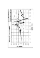
例えば、図7は、従来の圧電素子マイクロアクチュエータの共振試験データを示す図である。同図に示すように、圧電素子マイクロアクチュエータが動作する(圧電素子を励起する)場合、サスペンションの一番大きな反作用力によってサスペンションの共振現象が発生する。曲線160は、サスペンションの基板が揺動又は励起される時に形成される共振特性を図示し、曲線170は、マイクロアクチュエータの圧電素子が励起される時に形成される共振特性を図示している。図に示すように、曲線160と曲線170は同じような形状を描いている。
For example, FIG. 7 is a diagram showing resonance test data of a conventional piezoelectric element microactuator. As shown in the figure, when the piezoelectric element microactuator operates (excites the piezoelectric element), a resonance phenomenon of the suspension occurs due to the largest reaction force of the suspension.
従って、このような従来技術の欠点を解消する、改善されたシステムを提供することが望まれていた。
本発明の目的は、ヘッドジンバルアセンブリの共振性能を向上させたマイクロアクチュエータを提供することにある。 An object of the present invention is to provide a microactuator with improved resonance performance of a head gimbal assembly.
上記目的を達成するために、本発明は、ヘッドジンバルアセンブリに係り、このヘッドジンバルアセンブリは、マイクロアクチュエータと、スライダと、マイクロアクチュエータとスライダを支持するサスペンションと、を含む構成である。またマイクロアクチュエータはフレームと圧電素子を含む構成である。フレームは、スライダを支持する頂支持板と、サスペンションと連結する底支持板と、頂支持板と底支持板を互いに連結する一対のサイドアームと、を含む構成である。さらに頂支持板は回転板及びこの回転板とサイドアームとを連結する連結アームを含む構成である。圧電素子はサイドアーム上に装着されている。各圧電素子は励起されることによりサイドアームを選択的に動作させる。ここで、サスペンションはディンプルを備えているロードビームを含み、このディンプルは使用中に回転板と係合し且つこの回転板を支持する、ことを特徴とする。 In order to achieve the above object, the present invention relates to a head gimbal assembly, and the head gimbal assembly includes a microactuator, a slider, and a suspension that supports the microactuator and the slider. The microactuator includes a frame and a piezoelectric element. The frame includes a top support plate that supports the slider, a bottom support plate that is connected to the suspension, and a pair of side arms that connect the top support plate and the bottom support plate to each other. Furthermore, the top support plate includes a rotating plate and a connecting arm that connects the rotating plate and the side arm. The piezoelectric element is mounted on the side arm. Each piezoelectric element is operated to selectively operate the side arm. Here, the suspension includes a load beam having dimples, and the dimples engage with and support the rotating plate during use.
また、本発明は、ディスクドライブ装置に係り、このディスクドライブ装置は、マイクロアクチュエータ、スライダ、及びマイクロアクチュエータとスライダを支持するサスペンションからなるヘッドジンバルアセンブリと、ヘッドジンバルアセンブリと連結する駆動アームと、磁気ディスクと、磁気ディスクを駆動するスピンドルモータと、を含む構成である。またマイクロアクチュエータはフレームと圧電素子を含む構成である。フレームは、スライダを支持する頂支持板と、サスペンションと連結する底支持板と、頂支持板と持板を互いに連結する一対のサイドアームと、を含む構成である。さらに頂支持板は回転板及びこの回転板とサイドアームとを連結する連結アームを含む構成である。圧電素子はサイドアーム上に装着されている。各圧電素子は励起されることによりサイドアームを選択的に動作させる。サスペンションはディンプルを備えているロードビームを含み、このディンプルは使用中に回転板と係合し、且つこの回転板を支持することを特徴とする。 The present invention also relates to a disk drive device, which includes a micro-actuator, a slider, a head gimbal assembly comprising a micro-actuator and a suspension supporting the slider, a drive arm coupled to the head gimbal assembly, and a magnetic The configuration includes a disk and a spindle motor that drives the magnetic disk. The microactuator includes a frame and a piezoelectric element. The frame includes a top support plate that supports the slider, a bottom support plate that is connected to the suspension, and a pair of side arms that connect the top support plate and the holding plate to each other. Furthermore, the top support plate includes a rotating plate and a connecting arm that connects the rotating plate and the side arm. The piezoelectric element is mounted on the side arm. Each piezoelectric element is operated to selectively operate the side arm. The suspension includes a load beam having dimples, the dimples engaging with and supporting the rotating plate during use.
また、本発明は、マイクロアクチュエータに係り、このマイクロアクチュエータはフレームと圧電素子を含む構成である。フレームは、スライダを支持する頂支持板と、サスペンションと連結する底支持板と、頂支持板と底支持板を互いに連結する一対のサイドアームと、サイドアームの底支持板に隣接する位置に形成されているアームメンバーと、を含む構成である。また頂支持板は回転板と、この回転板とサイドアームとを連結する連結アームを含む構成である。さらに圧電素子はサイドアーム上に装着されており、各圧電素子は励起されることによりサイドアームを選択的に動作させる。 The present invention also relates to a microactuator, and the microactuator includes a frame and a piezoelectric element. The frame is formed at a position adjacent to the bottom support plate of the side arm, a top support plate that supports the slider, a bottom support plate that connects to the suspension, a pair of side arms that connect the top support plate and the bottom support plate to each other, and And an arm member. The top support plate includes a rotating plate and a connecting arm that connects the rotating plate and the side arm. Furthermore, the piezoelectric element is mounted on the side arm, and each piezoelectric element is activated to selectively operate the side arm.
また、本発明は、マイクロアクチュエータに係り、このマイクロアクチュエータはフレームと圧電素子を含む構成である。フレームは、スライダを支持する頂支持板と、サスペンションと連結する底支持板と、頂支持板と底支持板を互いに連結する一対のサイドアームと、を含む構成である。ここで、頂支持板は回転板と、この回転板とサイドアームとを連結する連結アームとを含む構成である。さらに圧電素子はサイドアーム上に装着されており、各圧電素子は励起されることによりサイドアームを選択的に動作させる。また各連結アームのサイドアームと互いに連結される位置には溝部が形成されている。 The present invention also relates to a microactuator, and the microactuator includes a frame and a piezoelectric element. The frame includes a top support plate that supports the slider, a bottom support plate that is connected to the suspension, and a pair of side arms that connect the top support plate and the bottom support plate to each other. Here, the top support plate includes a rotating plate and a connecting arm that connects the rotating plate and the side arm. Furthermore, the piezoelectric element is mounted on the side arm, and each piezoelectric element is activated to selectively operate the side arm. A groove portion is formed at a position where the side arms of the connecting arms are connected to each other.
また、本発明は、ヘッドジンバルアセンブリの製造方法に係り、この方法は、圧電素子をマイクロアクチュエータの相応するサイドアームに装着するステップと、スライダをマイクロアクチュエータフレームに装着するステップと、マイクロアクチュエータフレームをサスペンションに装着するステップと、圧電素子とサスペンションを電気的に接続するステップと、スライダとサスペンションに電気的に接続するステップと、圧電素子に対して電気的なテストを行うステップと、スライダに対して性能テストを行うステップと、ヘッドジンバルアセンブリを検査するステップと、を含むことを特徴とする。 The present invention also relates to a method for manufacturing a head gimbal assembly, the method comprising: attaching a piezoelectric element to a corresponding side arm of a microactuator; attaching a slider to a microactuator frame; Mounting on the suspension; electrically connecting the piezoelectric element and the suspension; electrically connecting the slider and the suspension; performing an electrical test on the piezoelectric element; and Performing a performance test and inspecting the head gimbal assembly.
また、本発明は、もう1つのヘッドジンバルアセンブリの製造方法に係り、この方法は、圧電素子をマイクロアクチュエータのサイドアームに装着するステップと、マイクロアクチュエータフレームをサスペンションに装着するステップと、圧電素子とサスペンションを電気的に接続するステップと、圧電素子に対して電気的なテストを行うステップと、スライダをマイクロアクチュエータフレームに装着するステップと、スライダとサスペンションに電気的に接続するステップと、スライダに対して性能テストを行うステップと、ヘッドジンバルアセンブリを検査するステップと、を含むことを特徴とする。 The present invention also relates to another method for manufacturing a head gimbal assembly, the method comprising: attaching a piezoelectric element to a side arm of a microactuator; attaching a microactuator frame to a suspension; Electrically connecting the suspension; electrically testing the piezoelectric element; mounting the slider to the microactuator frame; electrically connecting the slider to the suspension; and Performing a performance test and inspecting the head gimbal assembly.
また、本発明はもう1つのヘッドジンバルアセンブリの製造方法に係り、この方法は、マイクロアクチュエータフレームをサスペンションに装着するステップと、圧電素子をマイクロアクチュエータのサイドアームに装着するステップと、圧電素子とサスペンションを電気的に接続するステップと、圧電素子に対して電気的なテストを行うステップと、スライダをマイクロアクチュエータフレームに装着するステップと、スライダとサスペンションに電気的に接続するステップと、スライダに対して性能テストを行うステップと、ヘッドジンバルアセンブリを検査するステップと、を含むことを特徴とする。 The present invention also relates to another method for manufacturing a head gimbal assembly, which includes a step of attaching a microactuator frame to a suspension, a step of attaching a piezoelectric element to a side arm of the microactuator, a piezoelectric element and a suspension. Electrically connecting the slider, mounting the slider to the microactuator frame, electrically connecting the slider and the suspension, and the slider Performing a performance test and inspecting the head gimbal assembly.
また、本発明はマイクロアクチュエータの製造方法に係り、この方法は、一対のサイドアームとこのサイドアームと連結する底支持板を提供するステップと、回転板と連結アームからなる頂支持板を提供するステップと、圧電素子を提供し且つこの圧電素子をサイドアームに装着するステップと、接着剤により頂支持板を2つのサイドアームに接着するステップと、接着剤を硬化してマイクロアクチュエータを形成するステップと、マイクロアクチュエータを検査するステップと、を含むことを特徴とする。 The present invention also relates to a method of manufacturing a microactuator, which provides a step of providing a pair of side arms and a bottom support plate connected to the side arms, and a top support plate comprising a rotating plate and a connection arm. Providing a piezoelectric element and mounting the piezoelectric element to the side arm; bonding the top support plate to the two side arms with an adhesive; and curing the adhesive to form a microactuator. And inspecting the microactuator.
また、本発明はマイクロアクチュエータの製造方法に係り、この方法は、セラミック粉末材料を混合するステップと、混合したセラミック粉末材料をシート状材料に押圧するステップと、一対のサイドアームとこのサイドアームと連結する底支持板を提供し、接着剤により頂支持板をサイドアームの間に接着することによりフレームを形成するステップと、フレームを焼結することにより、頂支持板をサイドアームに固定するステップと、圧電素子を提供し且つこの圧電素子をサイドアームに装着することによりマイクロアクチュエータを形成するステップと、マイクロアクチュエータを検査するステップと、を含むことを特徴とする。 The present invention also relates to a method of manufacturing a microactuator, which includes a step of mixing a ceramic powder material, a step of pressing the mixed ceramic powder material against a sheet-like material, a pair of side arms, and the side arms. Providing a bottom support plate to be connected, forming a frame by adhering the top support plate between the side arms with an adhesive, and fixing the top support plate to the side arm by sintering the frame And forming a microactuator by providing the piezoelectric element and attaching the piezoelectric element to the side arm, and inspecting the microactuator.
また、本発明はマイクロアクチュエータの製造方法に係り、この方法は、セラミック粉末材料を混合するステップと、混合したセラミック粉末材料をシート状材料に押圧するステップと、シート状材料を加工して、一対のサイドアームと、このサイドアームと連結する底支持板と、回転板及びこの回転板とを連結する連結アームからなる頂支持板と、を形成するステップと、接着剤により頂支持板をサイドアームの間に接着することによりフレームを形成するステップと、フレームを焼結することにより、頂支持板をサイドアームに固定するステップと、圧電素子を提供し且つこの圧電素子をフレームのサイドアームに装着することによりマイクロアクチュエータを形成するステップと、マイクロアクチュエータを検査するステップと、を含むことを特徴とする。 The present invention also relates to a method of manufacturing a microactuator, which includes a step of mixing a ceramic powder material, a step of pressing the mixed ceramic powder material against a sheet-like material, and processing the sheet-like material to form a pair. Forming a side arm, a bottom support plate connected to the side arm, a top support plate comprising a rotation plate and a connection arm connecting the rotation plate, and the side support arm to the side support arm with the adhesive. Forming a frame by adhering to each other, fixing the top support plate to the side arm by sintering the frame, and providing a piezoelectric element and attaching the piezoelectric element to the side arm of the frame Forming a microactuator and inspecting the microactuator. It is characterized in.
以下、図面を参照して本発明の具体的な実施例について説明する。なお、添付した図面の中で、同一部分または相当する部分には同一の符号を付す。既述したように、本発明は、ヘッドジンバルアセンブリ内の共振性能を改善すると共に、マイクロアクチュエータの使用によりスライダを優れた精度で駆動させることを課題とする。また本発明は、回転式圧電素子マイクロアクチュエータを提供することにより、ヘッドジンバルアセンブリの共振性能を向上させる。ヘッドジンバルアセンブリの共振性能を向上させることにより、ディスクドライブ装置の性能特性も向上させることができる。 Hereinafter, specific embodiments of the present invention will be described with reference to the drawings. In the attached drawings, the same or corresponding parts are denoted by the same reference numerals. As described above, an object of the present invention is to improve the resonance performance in the head gimbal assembly and to drive the slider with excellent accuracy by using a microactuator. The present invention also improves the resonance performance of the head gimbal assembly by providing a rotary piezoelectric element microactuator. By improving the resonance performance of the head gimbal assembly, the performance characteristics of the disk drive device can also be improved.
以下、ヘッドジンバルアセンブリに適用されるマイクロアクチュエータの幾つかの実施形態について説明する。なお、圧電素子マイクロアクチュエータは、図示したヘッドジンバルアセンブリの特定の構造にかかわらず、マイクロアクチュエータを備えることで共振性能を向上させるいずれかのディスクドライブ装置に適用できることは勿論である。即ち、本発明はいずれかの分野のいずれかのマイクロアクチュエータを含む適宜な装置に応用されることができる。 Hereinafter, some embodiments of the microactuator applied to the head gimbal assembly will be described. Of course, the piezoelectric element microactuator can be applied to any disk drive device in which the resonance performance is improved by providing the microactuator regardless of the specific structure of the head gimbal assembly shown in the figure. That is, the present invention can be applied to an appropriate apparatus including any microactuator in any field.
図8乃至図13は、本発明の模範的な実施形態に係る圧電素子マイクロアクチュエータ212を含むヘッドジンバルアセンブリ210を示す図である。ヘッドジンバルアセンブリ210は、圧電素子マイクロアクチュエータ212と、スライダ214と、圧電素子マイクロアクチュエータ212及びスライダ214を支持するサスペンション216と、を含む構成である。
FIGS. 8-13 illustrate a
図8,図11,図12に示すように、サスペンション216は、基板218と、ロードビーム220と、ヒンジ222と、フレキシャ224と、フレキシャ224上に位置する内外サスペンショントレース226、227と、を含む構成である。基板218は、サスペンション216をディスクドライブ装置のボイスコイルモータ(VCM)の駆動アームに連結させるための取付け孔228を備えている。この基板218の形状は、ディスクドライブ装置の配置及び種類によって異なっていてもよい。また基板218は、比較的に硬い材料又は剛性を備えた材料(例えば金属製等)により製造され、これによりサスペンション216を安定的にボイスコイルモータの駆動アームに固定させることができる。
As shown in FIGS. 8, 11, and 12, the
ヒンジ222は、例えば半田付け等の方式により、基板218とロードビーム220上に連結される。図に示すように、このヒンジ222は、基板218の取付け孔228とマッチングする孔230を有している。またヒンジ222は、ロードビーム220を支持するために用いられる固持部材232を含む構成である。
The
ロードビーム220は、例えば半田付け等の方式により、ヒンジ222の固持部材232に固定されている。このロードビーム220には、圧電素子マイクロアクチュエータ212と係合するディンプル234が形成されている(図10乃至図12を参照)。図10に示すように、ディンプル234はスライダ214の中心に位置している。
The
フレキシャ224は、例えば溶接又は重ね合わせ(lamination)等の方式により、ヒンジ222とロードビーム220に装着される。このフレキシャ224は頂部区域若しくはサスペンションタング238を含む構成であり、このサスペンションタング238は、圧電素子マイクロアクチュエータ212をサスペンション216に固定するために使用される(図10乃至図12を参照)。フレキシャ224のサスペンショントレース226,227は、複数の接続パッド240(外部制御システムと連結する)と、スライダ214と、圧電素子マイクロアクチュエータ212上の圧電素子242,243と、を電気的に接続する。これらのサスペンショントレース226、227はフレキシブルプリント回路(FPC)を適用することができ、適宜な数の導線が備えられている。
The
図9、図10、図12に示すように、接続パッド244は内部サスペンショントレース226に直接接続されて、当該内部サスペンショントレース226を圧電素子242,243の接続パッド246に電気的に接続させる。同様に、接続パッド248は外部サスペンショントレース227に直接接続されて、当該外部サスペンショントレース227をスライダ214上の接続パッド250に電気的に接続させる。
As shown in FIGS. 9, 10, and 12, the
ディスクドライブ装置はボイスコイルモータを備えており、このボイスコイルモータにより駆動アームが回転制御され、更には、ヘッドジンバルアセンブリ210を駆動制御させる。従って、スライダ214及び記録/再生ヘッドは、ディスクドライブ装置の磁気ディスクのトラック上で動作することができる。圧電素子マイクロアクチュエータ212により、ディスクドライブ装置の迅速且つ正確な位置決め制御を実現させ、更にはスライダ動作中のシーク時間と位置決め時間を減少させることもできる。このように圧電素子マイクロアクチュエータ212を装着したディスクドライブ装置は、二駆動システムを形成しており、記録/再生ヘッドに対して、ボイスコイルモータが低精度な位置調整を行い、圧電素子マイクロアクチュエータが高精度な位置調整を行う構成とすることができる。
The disk drive device includes a voice coil motor, and the drive arm is rotationally controlled by the voice coil motor, and further, the
図12、図13は、スライダ214及びサスペンション216から圧電素子マイクロアクチュエータ212を分離した斜視図である。同図に示すように、圧電素子マイクロアクチュエータ212は、マイクロアクチュエータフレーム252と、このマイクロアクチュエータのフレーム252のサイドアームに装着されている圧電素子242、243と、を含む構成である。
12 and 13 are perspective views in which the
マイクロアクチュエータフレーム252は、頂支持板254と、底支持板256と、頂支持板254及び底支持板256を連結するサイドアーム258,259と、を含む構成である。頂支持板254は、回転板260と、回転板260を支持してサイドアーム258,259に連結する連結アーム若しくは連結ブリッジ262,264と、を備えている。なお、マイクロアクチュエータフレーム252は、金属材料から形成されることが好ましいが、いずれかの適宜な材料(例えば、セラミック材料)から形成されてもよい。
The
サイドアーム258,259は、頂支持板254と底支持板256を介し相対して形成されている。図に示すように、底支持板256と連結するサイドアーム258,259の間には内凹部(inner notch)若しくはスペース257が形成されている。これような構造によりサイドアーム258,259は、より大きくて効率的な長さと、より広い動作自由度を持つことができる。
The
図12に示すように、連結ブリッジ262は曲線構造を有し、且つ相反する端部262a、262bを備え、連結ブリッジ264は曲線構造を有し、且つ相反する端部264a、264bを備えている。端部262a、264aは回転板260と連結し、また端部262b、264bは、相対するサイドアーム258,259に連結されている。本実施例において、端部262b、264bはY軸上の同じ位置で相対するサイドアーム258,259に連結されており、即ち、端部262b、264bの連結点から相対するサイドアーム258,259の末端までの距離は同一になっている。また端部262a、264aは回転板260の中心を対称軸として点対称にこの回転板260に連結されている。即ち、端部262a、264aの連結点は、回転板260の重心に対して対称となるように設けられている。圧電素子242,243が使用中に励起された場合、このような構造により、回転板260はその重心を中心として回転する。なお、連結ブリッジ262,264は他の適宜な形状や連結構造に形成されてあってもよい。
As shown in FIG. 12, the connecting
マイクロアクチュエータフレーム252のサイドアーム258,259の外側表面には、圧電素子242,243が装着されている。この圧電素子242,243には接続パッド246(例えば、2つ)が設置されている。この接続パッドは圧電素子242,243を内部サスペンショントレース226上に電気的に接続するために使用される。各圧電素子242,243は、セラミック圧電素子、薄膜圧電素子、若しくは、PMN−PT圧電素子等を適用でき、また単層構造若しくは多層構造を適用することもできる。
図9、図10、図12に示すように、底支持板256は、マイクロアクチュエータフレーム252をサスペンション216に装着するために用いられる。具体的には、底支持板256は、エポキシ接着剤、樹脂、若しくはレーザー溶接等の方式により、フレキシャ224の頂部区域又はサスペンションタング238上に固定されている。また、圧電素子242,243上に設置されている圧電接続パッド246(例えば、2つの接続パッド)は、電気接続ボール266(金ボール半田付け又はハンダボール半田付け;GBB or SBB)により、内部サスペンショントレース226の接続パッド244に電気的に連結されている。これにより、内部サスペンショントレース226を通じて圧電素子242,243に電圧を印加させる。
As shown in FIGS. 9, 10, and 12, the
本実施形態において、内部サスペンショントレース226の1つの接続パッド244は、電極部270及び接地部272(ground part)を含む構成である(図12を参照)。接続パッド244は、接地部272によりサスペンション216(例えば、ステンレス材料からなる)を接地させ、また複数の接続パッド240により、内部サスペンショントレース226の1本のトレースを圧電素子242,243に連結させることで、これらの接続パッド240と外部制御システムとの連結が確保される。
In this embodiment, one
頂支持板254は、マイクロアクチュエータフレーム252をスライダ214上に固定させる。具体的には、回転板260は、重合体積層、エポキシ層、若しくは、金属層からなる階段部272に構成される。スライダ214は、回転板260の階段部274に部分的に装着され、これにより圧電素子マイクロアクチュエータ212が動作する場合、スライダ214と連結アーム或は連結ブリッジ262,264が当接せず、若しくは互いの干渉が防止される。また、スライダ214上の複数の接続パッド250(例えば6つの接続パッド)は、例えば電気接続ボール278(金ボール半田付け又はハンダボール半田付け;GBB or SBB)により、頂支持部276の接続パッド248に電気的に連結される。これにより、頂支持部254をスライダ214に接続させ、またスライダ214及びその記録/再生ヘッドをサスペンション216の外部サスペンショントレース227に電気的に接続させる。
The
本実施形態において、各外部サスペンショントレース227は、それぞれスライダ214の側辺と隣接する湾曲部268を含む構成である。圧電素子マイクロアクチュエータ212が動作する場合、このような構造は、外部サスペンショントレース227の剛性により発生した応力を逃すのに役立ち、従って、圧電素子マイクロアクチュエータ212が更にスムーズに動作させることができる。
In the present embodiment, each
また、サスペンションロードビーム220のディンプル234は回転板260の重心を支持している。これにより、圧電素子マイクロアクチュエータ212とディンプル234の間には平行ギャップがなくなり、従って容易に製造することができる。この構造は従来の技術と異なり、具体的にはギャップを制御する、或いはサスペンションタングの剛性を制御することによってサスペンションタングの変形を防止する必要がなくなる。
The
本実施形態において、スライダ214は、頂支持板256の回転板260に装着され、これによりスライダ214の重心と回転板260の重心が充分に重なり合うことになる。また、圧電素子マイクロアクチュエータ212の底支持板254はサスペンションタング238上に装着され、これにより回転板260の重心とサスペンション216のディンプル234が充分に重なり合うことになる。圧電素子242,243を励起させることで回転板260を回転する場合、スライダ214及び回転板260は、この構造によりサスペンションのディンプル234を中心として回転することができる。
In the present embodiment, the
図14(a)は,圧電素子マイクロアクチュエータ212の2つの圧電素子242,243の間の電気的な1つの連結構造を示す図であり、図14(b)はその動作電圧を示す図である。同図に示すように、これらの圧電素子242,243は、同じ極化方向を有し、且つ共用接地端子を有している。そして、圧電素子242,243を駆動させるためにサイン電圧が印加される。図15(a)は、弛緩状態になっている圧電素子マイクロアクチュエータ212を示し、図15(b)は、電圧を印加後の圧電素子マイクロアクチュエータ212を示す図である。図15(b)に示すように、駆動電圧が第一の半周期になった場合、圧電素子242,243は収縮され、2つのサイドアーム258,259が外側に向かって湾曲される。2つの連結ブリッジ262,264は回転板260の重心に対して、お互いに離れるように回転板260に連結されており、また回転板260上に装着されたスライダ214は、重心を中心として右側に回転される。電圧が第二の半周期になった場合、圧電素子242,243は復元若しくは拡張され、またスライダ214も回転しながら元に戻される。
FIG. 14A is a diagram showing one electrical connection structure between the two
図16(a)は、圧電素子マイクロアクチュエータ212の2つの圧電素子242,243の間の電気的な他の連結構造を示す図であり、図16(b)はその動作電圧を示す図である。同図に示すように、これらの圧電素子242,243は、相反する極化方向を有し、また同じ接地端子を有している。そして、2つの異なるサイン電圧を圧電素子242,243に印加し、これにより圧電素子242,243をそれぞれ駆動させる。駆動電圧が第一の半周期になった場合、圧電素子242,243のうち一方がプラス性の極化方向を持ち、もう一方の圧電素子はマイナス性の極化方向を持つ。これにより圧電素子242,243は収縮され、2つのサイドアーム258,259が外側に向かって湾曲される。2つの連結ブリッジ262,264は回転板260の重心に対して、お互いに離れるように回転板260に連結されており、また回転板260の上に装着されたスライダ214は、重心を中心として右側に回転される(図15(b)を参照)。電圧が第二の半周期になった場合、圧電素子242,243は復元若しくは拡張され、またスライダ214も回転しながら元に戻される。
FIG. 16A is a diagram showing another electrical connection structure between the two
図17、図18は圧電素子マイクロアクチュエータ212の共振テストのデータを示す図であり、図17は共振増幅率を示し、図18は共振位相を示している。図に示すように、曲線280,284はサスペンションの基板が揺動又は励起される時の共振増幅率と位相を示している。曲線282,286は圧電素子マイクロアクチュエータ212の圧電素子242,243が励起される時の共振増幅率と位相を示している。圧電素子マイクロアクチュエータ212は、従来の揺動方式ではなく回転方式により動作するため、圧電素子マイクロアクチュエータ212の動作過程において、サスペンションには更に小さい反作用力が印加され、これにより共振性能が向上されるようになった。即ち、圧電素子マイクロアクチュエータ212は、図7に示す従来のモデルのように、サスペンション共振モデルが形成されない。これにより圧電素子マイクロアクチュエータ212は、ディスクドライブ装置の性能特性を顕著に改善させ、また高いサーボ帯域幅を達成させることができる。
17 and 18 are diagrams showing resonance test data of the
同様に、圧電素子マイクロアクチュエータ212は従来の揺動方式ではなく回転方式により動作するため、サスペンション構造、特にサスペンションタングの構造の簡素化を図ることができる。これによりサスペンションの製造が簡単になり、製造コストの低減を図ることができる。また、荷重を減らすことにより、ヘッドジンバルアセンブリの静態及び動態性能(例えば、防振性能)を向上させることができる。
Similarly, since the
図19は、本発明の別の実施形態における圧電素子マイクロアクチュエータ312を示す図である。この実施形態において、剛性材料若しくは剛性塊390(金属材料から構成される)は、マイクロアクチュエータフレーム252のサイドアーム258と259の間に装着され、また底支持板256により支持されている。圧電素子マイクロアクチュエータ312が動作する時、このような構造はサイドアーム258と259の不協調な変形を防止することができる。圧電素子マイクロアクチュエータ312のその他の部材は、記述した圧電素子マイクロアクチュエータ212と基本的に同じなので、ここではマイクロアクチュエータ212と同じ符号を付して表示する。構造において少し異なる点があるが、圧電素子マイクロアクチュエータ312と圧電素子マイクロアクチュエータ212は、実質的に同様の動作原理である。
FIG. 19 is a diagram showing a
図19aは、本発明の別の実施形態における圧電素子マイクロアクチュエータ312aを示す図である。このマイクロアクチュエータ312aは、図19に示すマイクロアクチュエータ312と類似しており、実施形態において異なる点は、底支持板256aの厚さがサイドアーム258、259の高さと同一に設置されている点である。圧電素子マイクロアクチュエータ312aが動作する時、このような構造や材料はサイドアーム258と259の不協調な変形を防止することができる。
FIG. 19a is a diagram showing a
図20は、本発明の別の実施形態における圧電素子マイクロアクチュエータ412を示す図である。この実施形態において、マイクロアクチュエータフレーム252のサイドアーム258,259の底支持板256に隣接する箇所には、アームメンバー492,494(arm member)が形成されている。同図に示すように、これらのアームメンバー492,494は底支持板256に向けて湾曲され、また底支持板256と接合する自由端を備えている。このような構造はサイドアーム258と259の不協調な変形を防止することができる。圧電素子マイクロアクチュエータ412のその他の部材は、記述した圧電素子マイクロアクチュエータ212と基本的に同じなので、ここではマイクロアクチュエータ212と同じ符号を付して表示する。構造において少し異なる点があるが、圧電素子マイクロアクチュエータ412と圧電素子マイクロアクチュエータ212は、実質的に同様の動作原理である。
FIG. 20 is a diagram showing a
図21は、本発明の別の実施形態における圧電素子マイクロアクチュエータ512を示す図である。この実施形態において、マイクロアクチュエータフレーム252のサイドアーム258,259の底支持板256に隣接する箇所には、アームメンバー592,594が形成されている。同図に示すように、これらのアームメンバー592,594は互いに対向して延在され、また底支持板256とほぼ平行している。またこれらのアームメンバー592,594は、互いに接合する自由端を備えている。このような構造はサイドアーム258と259の不協調な変形を防止することができる。圧電素子マイクロアクチュエータ512のその他の部材は、記述した圧電素子マイクロアクチュエータ212と基本的に同じなので、ここではマイクロアクチュエータ212と同じ符号を付して表示する。構造において少し異なる点があるが、圧電素子マイクロアクチュエータ512と圧電素子マイクロアクチュエータ212は、実質的に同様の動作原理である。
FIG. 21 is a diagram showing a
図22は、本発明の別の実施形態における圧電素子マイクロアクチュエータ612を示す図である。この実施形態において、各連結ブリッジ262,264との連結部位に隣接する箇所には、例えば部分的なエッチング方式により溝部696が形成されている(溝部696の一方だけを図示している)。図に示すように、この溝部696は、使用中においてスライダ214に対向するように連結ブリッジ262,264の前表面若しくは内表面に形成される。このように部分的に形成された溝部696は、成型過程を容易にすることができる。圧電素子マイクロアクチュエータ612のその他の部材は、記述した圧電素子マイクロアクチュエータ212と基本的に同じなので、ここではマイクロアクチュエータ212と同じ符号を付して表示する。構造において少し異なる点があるが、圧電素子マイクロアクチュエータ612と圧電素子マイクロアクチュエータ212は、実質的に同様の動作原理である。
FIG. 22 is a diagram showing a
図23は、本発明の別の実施形態における圧電素子マイクロアクチュエータ712を示す図である。この実施形態において、各連結ブリッジ262,264のサイドアーム258,259との連結部位に隣接する箇所には、例えば部分的なエッチング方式により溝部796が形成されている。図に示すように、この溝部796は、使用中においてスライダ214の反対面に向かうように連結ブリッジ262,264の後表面に形成される。このように部分的に形成された溝部796は成型過程を容易にさせることができる。圧電素子マイクロアクチュエータ712のその他の部材は、記述した圧電素子マイクロアクチュエータ212と基本的に同じなので、ここではマイクロアクチュエータ212と同じ符号を付して表示する。構造において少し異なる点があるが、圧電素子マイクロアクチュエータ712と圧電素子マイクロアクチュエータ212は、実質的に同様の動作原理である。
FIG. 23 is a diagram showing a
図24は、本発明の別の実施形態における圧電素子マイクロアクチュエータ812を示す図である。この実施形態において、底支持板256は、サイドアーム258,259との連結部位に隣接する箇所に通孔898が形成されている(通孔898の一方だけを図示している)。これらの通孔898は、圧電素子マイクロアクチュエータ812が動作する時、連結剛性を低減させる効果がある。圧電素子マイクロアクチュエータ812のその他の部材は、記述した圧電素子マイクロアクチュエータ212と基本的に同じなので、ここではマイクロアクチュエータ212と同じ符号を付して表示する。構造において少し異なる点があるが、圧電素子マイクロアクチュエータ812と圧電素子マイクロアクチュエータ212は、実質的に同様の動作原理である。
FIG. 24 is a diagram showing a
図25は、本発明の別の実施形態における圧電素子マイクロアクチュエータ912を示す図である。この実施形態において、底支持板256は、サイドアーム258,259と隣接する箇所に、例えば部分的なエッチング方式による溝部988が形成されている。これらの溝部988は、圧電素子マイクロアクチュエータ912が動作する時、連結剛性を低減させる効果がある。圧電素子マイクロアクチュエータ912のその他の部材は、記述した圧電素子マイクロアクチュエータ212と基本的に同じなので、ここではマイクロアクチュエータ212と同じ符号を付して表示する。構造において少し異なる点があるが、圧電素子マイクロアクチュエータ912と圧電素子マイクロアクチュエータ212は、実質的に同様の動作原理である。
FIG. 25 is a diagram showing a
図26は、本発明の別の実施形態における圧電素子マイクロアクチュエータ1012を示す図である。この実施形態において、底支持板256は、サイドアーム258,259と隣接する箇所に、例えば部分的なエッチング方式による溝部1088が形成されている。また、各連結ブリッジ262,264のサイドアーム258,259との連結部位に隣接する箇所には、例えば部分的なエッチング方式により溝部1096が形成されている(溝部1096の一方だけを図示している)。図に示すように、この溝部1096は、使用中においてスライダ214に対向するように連結ブリッジ262,264の前表面若しくは内表面に形成される。これらの溝部1088、1096は、圧電素子マイクロアクチュエータ1012が動作する時、連結剛性を低減させる効果がある。圧電素子マイクロアクチュエータ1012のその他の部材は、記述した圧電素子マイクロアクチュエータ212と基本的に同じなので、ここではマイクロアクチュエータ212と同じ符号を付して表示する。構造において少し異なる点があるが、圧電素子マイクロアクチュエータ1012と圧電素子マイクロアクチュエータ212は、実質的に同様の動作原理である。
FIG. 26 is a diagram showing a
図27は、本発明の別の実施形態における圧電素子マイクロアクチュエータ1112を示す図である。この実施例において、底支持板256は、サイドアーム258,259と隣接する箇所に通孔1198が形成されている(通孔1198の一方だけを図示している)。なお、各連結ブリッジ262,264のサイドアーム258,259との連結部位に隣接する箇所には、例えば部分的なエッチング方式により溝部1196が形成されている(溝部1196の一方だけを図示している)。図に示すように、溝部1196は、使用中においてスライダ214に対向するように連結ブリッジ262,264の前表面若しくは内表面に形成される。これらの通孔1198及び溝部1196は、圧電素子マイクロアクチュエータ1112が動作する時、連結剛性を低減させる効果がある。圧電素子マイクロアクチュエータ1112のその他の部材は、記述した圧電素子マイクロアクチュエータ212と基本的に同じなので、ここではマイクロアクチュエータ212と同じ符号を付して表示する。構造において少し異なる点があるが、圧電素子マイクロアクチュエータ1112と圧電素子マイクロアクチュエータ212は、実質的に同様の動作原理である。
FIG. 27 is a diagram showing a
図22乃至図27に示す通孔または溝部は、いずれかの適宜な組み合わせによりマイクロアクチュエータフレーム252に形成されることが可能である。また、これらの通孔または溝部には、圧電素子マイクロアクチュエータが動作する時の連結剛性を低減させる適宜な構造があることはもちろんである。
The through holes or grooves shown in FIGS. 22 to 27 can be formed in the
図28は、本発明の実施形態における圧電素子マイクロアクチュエータの製造及び組立の工程を示すフローチャートである。工程開始後(図28のステップ1)に、圧電素子をマイクロアクチュエータフレームに取り付ける(図28のステップ2)。このマイクロアクチュエータフレーム及び圧電素子は、図8乃至図27に示した実施形態の構造を持つことができる。次に、スライダをマイクロアクチュエータフレームに装着する(図28のステップ3)。続いて、マイクロアクチュエータフレームをヘッドジンバルアセンブリのサスペンションに装着する(図28のステップ4)。このマイクロアクチュエータフレームは、図8乃至図12に示す方式によりサスペンションに装着される。続いて、圧電素子とスライダをサスペンションに電気的に接続する(図28のステップ5及びステップ6)、また圧電素子に対して電気的なテスト、及びスライダに対して性能テストを行う(図28のステップ7及びステップ8)。最後に、組み合わせに対して検査を行い(図28のステップ9)、これにより、製造及び組立の工程が終了する(図28のステップ10)。
FIG. 28 is a flowchart showing manufacturing and assembly steps of the piezoelectric element microactuator according to the embodiment of the present invention. After starting the process (
図29は、本発明の他の実施形態における圧電素子マイクロアクチュエータの製造及び組立の工程を示すフローチャートである。工程開始後(図29のステップ1)に、圧電素子をマイクロアクチュエータフレームに取り付ける(図29のステップ2)。このマイクロアクチュエータフレーム及び圧電素子は、図8乃至図27に示した実施形態の構造を持つことができる。次に、このマイクロアクチュエータフレームをヘッドジンバルアセンブリのサスペンションに装着する(図29のステップ3)。このマイクロアクチュエータフレームは、図8乃至図12に示す方式によりサスペンションに装着される。続いて、圧電素子をサスペンションに電気的に接続し(図29のステップ4)、また圧電素子に対して電気的なテストを行う(図29のステップ5)。次に、スライダを該マイクロアクチュエータフレームに装着する(図29のステップ6)。続いて、スライダをサスペンションに電気的に接続し(図29のステップ7)、またスライダに対して性能テストを行う(図29のステップ8)。最後に、組み合わせに対して検査を行い(図29のステップ9)、これにより製造及び組立の工程が終了する(図29のステップ10)。
FIG. 29 is a flowchart showing steps of manufacturing and assembling a piezoelectric element microactuator according to another embodiment of the present invention. After the start of the process (
図30は、本発明の他の実施形態における圧電素子マイクロアクチュエータの製造及び組立の工程を示すフローチャートである。工程開始後(図30のステップ1)に、マイクロアクチュエータフレームをヘッドジンバルアセンブリのサスペンションに装着する(図30のステップ2)。このマイクロアクチュエータフレームは、図8乃至図27に示す構造を持ち、また図8乃至図27に示す方式によりサスペンションに装着される。次に、圧電素子をマイクロアクチュエータフレームに装着する(図30のステップ3)。このマイクロアクチュエータフレームは図8乃至図27に示す実施形態における構造を持つことができる。続いて、圧電素子をサスペンションに電気的に接続し(図30のステップ4)、また、圧電素子に対して電気的なテストを行う(図30のステップ5)。続いて、スライダをマイクロアクチュエータフレームに装着する(図30のステップ6)。さらに、スライダをサスペンションに電気的に接続し(図30のステップ7)、またスライダに対して性能テストを行う(図30のステップ8)。最後に、組み合わせに対して検査を行い(図30のステップ9)、これにより製造及び組立の工程が終了する(図30のステップ10)。
FIG. 30 is a flowchart showing steps of manufacturing and assembling a piezoelectric element microactuator according to another embodiment of the present invention. After starting the process (
図31に示すように、本発明の実施形態におけるマイクロアクチュエータの製造方法では、工程開始後(ステップ400)に、まず一対のサイドアームと、このサイドアームと連結する底支持板を提供する(ステップ401)。また、回転板と連結アームからなる頂支持板を提供する(ステップ402)。続いて、圧電素子を提供し、且つこの圧電素子をサイドアームに装着する(ステップ403)。その後、接着剤により頂支持板を2つのサイドアームの間に接着する(ステップ404)。この接着剤を硬化させて、マイクロアクチュエータを形成する(ステップ405)。さらにマイクロアクチュエータを検査し(ステップ406)、これにより製造工程が終了する(ステップ407)。 As shown in FIG. 31, in the microactuator manufacturing method of the embodiment of the present invention, after the start of the process (step 400), first, a pair of side arms and a bottom support plate connected to the side arms are provided (steps). 401). In addition, a top support plate including a rotating plate and a connecting arm is provided (step 402). Subsequently, a piezoelectric element is provided, and the piezoelectric element is attached to the side arm (step 403). Thereafter, the top support plate is bonded between the two side arms with an adhesive (step 404). The adhesive is cured to form a microactuator (step 405). Further, the microactuator is inspected (step 406), thereby completing the manufacturing process (step 407).
図32は、上記製造方法を詳細に説明するための図である。まず、回転板417及び回転板417の両側に形成されている連結アーム418を含む頂支持板416を提供する。同時に、底支持板411及びこの底支持板411の両側にそれぞれ連結されている一対のサイドアーム413を提供する。その後、圧電素子414を提供し、且つこの圧電素子414をサイドアーム413に装着する。その後、サイドアーム413の内側に接着剤415(例えば、エポキシ接着剤)を塗布し(頂支持板416の連結アーム418のエッジに塗布する、若しくは両方に塗布することもできる)、また頂支持板416を2つのサイドアーム413の間に配置することで、頂支持板416と2つのサイドアーム413が接着剤415により連結される。その後、接着剤415を硬化させて、頂支持板416を固定させる。最後に、この部品を検査する。
FIG. 32 is a diagram for explaining the manufacturing method in detail. First, the
図33に示すように、本発明の他の実施形態におけるマイクロアクチュエータの製造方法では、工程開始後(ステップ500)、まずセラミック粉末材料を混合する(ステップ501)。その後、混合したセラミック粉末材料をシート状材料に押圧する(ステップ502)。シート状材料を加工して、回転板及びこの回転板と連結する連結アームからなる頂支持板を形成する(ステップ503)。また、一対のサイドアームとこのサイドアームと連結する底支持板を提供し、接着剤によって頂支持板をサイドアームの間に接着することによりフレームを形成する(ステップ504)。さらにフレームを焼結することにより、頂支持板をサイドアームに固定する(ステップ505)。圧電素子を提供し、且つこの圧電素子をサイドアームに装着することによりマイクロアクチュエータを形成する(ステップ506)。最後に、マイクロアクチュエータを検査し(ステップ507)、これにより製造工程が終了する(ステップ508)。 As shown in FIG. 33, in the method for manufacturing a microactuator according to another embodiment of the present invention, after starting the process (step 500), first, the ceramic powder material is mixed (step 501). Thereafter, the mixed ceramic powder material is pressed against the sheet material (step 502). The sheet-like material is processed to form a top support plate including a rotating plate and a connecting arm connected to the rotating plate (step 503). Further, a pair of side arms and a bottom support plate connected to the side arms are provided, and a frame is formed by bonding the top support plate between the side arms with an adhesive (step 504). Further, the top support plate is fixed to the side arm by sintering the frame (step 505). A piezoelectric element is provided, and the microactuator is formed by attaching the piezoelectric element to the side arm (step 506). Finally, the microactuator is inspected (step 507), thereby completing the manufacturing process (step 508).
なおステップ505において、焼結温度を600〜800℃に設置することが好ましい。この温度範囲の場合、焼結工程を充分に実施することができ、これにより焼結品質を確保することができる。ここで、頂支持板、サイドアーム、及びサイドアームと連結する底支持板はセラミック材料から形成されるため、焼結工程により、両者が固く固定されてマイクロアクチュエータを形成することができる。
In
図34に示すように、本発明の他の実施形態におけるマイクロアクチュエータの製造方法では、まず、セラミック粉末材料を混合する(ステップ601)。混合したセラミック粉末材料をシート状材料に押圧する(ステップ602)。シート状材料を加工して、一対のサイドアーム、このサイドアームと連結する底支持板、回転板、この回転板と連結する連結アームからなる頂支持板、を形成する(ステップ603)。その後接着剤により、頂支持板をサイドアームの間に接着することによりフレームを形成する(ステップ604)。フレームを焼結することにより、頂支持板をサイドアームに固定する(ステップ605)。圧電素子を提供し、且つこの圧電素子をフレームのサイドアームに装着することによりマイクロアクチュエータを形成する(ステップ606)。最後に、マイクロアクチュエータを検査する(ステップ607)。 As shown in FIG. 34, in the method of manufacturing a microactuator according to another embodiment of the present invention, first, a ceramic powder material is mixed (step 601). The mixed ceramic powder material is pressed against the sheet-like material (step 602). The sheet-like material is processed to form a pair of side arms, a bottom support plate connected to the side arms, a rotary plate, and a top support plate consisting of a connection arm connected to the rotary plate (step 603). Thereafter, the top support plate is bonded between the side arms with an adhesive to form a frame (step 604). The top support plate is fixed to the side arm by sintering the frame (step 605). A microactuator is formed by providing a piezoelectric element and attaching the piezoelectric element to a side arm of the frame (step 606). Finally, the microactuator is inspected (step 607).
本発明の幾つかの実施形態における圧電素子マイクロアクチュエータ212、312、312a、412、512、612、712、812、912、1012、1112を含むヘッドジンバルアセンブリ210は、ディスクドライブ装置(HDD)に適用されることができる。このディスクドライブ装置は、図1に示す構造を適用することができる。ディスクドライブ装置の構造、動作及び製造プロセスは、当業者に広く周知されている技術であるため、それに対しての説明は省略する。圧電素子マイクロアクチュエータは、これを利用するいずれかの圧電素子マイクロアクチュエータを備えたディスクドライブ装置、若しくは圧電素子マイクロアクチュエータを備えた何れかの装置に応用することができる。具体的には、この圧電素子マイクロアクチュエータは、高い回転速度(RPM)を備えたディスクドライブ装置に適用されることができる。
A
以上、好ましい実施形態に従って本発明を説明したが、本発明は上記の実施形態に限定されるものではなく、本発明の精神から逸脱せずに様々な変形が可能であり、そして本発明は本明細書に記載した細部に限定されるものではない。 Although the present invention has been described according to the preferred embodiments, the present invention is not limited to the above-described embodiments, and various modifications can be made without departing from the spirit of the present invention. It is not limited to the details described in the specification.
210:ヘッドジンバルアセンブリ、212:圧電素子マイクロアクチュエータ、214:スライダ、216:サスペンション、218:基板、220:ロードビーム、222:ヒンジ、224:フレキシャ、226:サスペンショントレース、234:ディンプル、238:サスペンションタング、242、243:圧電素子、252:マイクロアクチュエータフレーム、254:頂支持板、256:底支持板、258、259:サイドアーム、260:回転板、262、264:連結ブリッジ、
312:圧電素子マイクロアクチュエータ、390:剛性材料、
412:圧電素子マイクロアクチュエータ、492、494:アームメンバー、
512:圧電素子マイクロアクチュエータ、592、594:アームメンバー、
612:圧電素子マイクロアクチュエータ、696:溝部、
712:圧電素子マイクロアクチュエータ、796:溝部、
812:圧電素子マイクロアクチュエータ、898:通孔、
912:圧電素子マイクロアクチュエータ、988:溝部、
1012:圧電素子マイクロアクチュエータ、1088、1096:溝部、
1112:圧電素子マイクロアクチュエータ、1196:溝部、1198:通孔
210: head gimbal assembly, 212: piezoelectric element microactuator, 214: slider, 216: suspension, 218: substrate, 220: load beam, 222: hinge, 224: flexure, 226: suspension trace, 234: dimple, 238: suspension Tongue, 242, 243: piezoelectric element, 252: microactuator frame, 254: top support plate, 256: bottom support plate, 258, 259: side arm, 260: rotating plate, 262, 264: connecting bridge,
312: Piezoelectric element microactuator, 390: Rigid material,
412: Piezoelectric element microactuator, 492, 494: Arm member,
512: Piezoelectric element microactuator, 592, 594: Arm member,
612: Piezoelectric element microactuator, 696: Groove,
712: Piezoelectric element microactuator, 796: Groove,
812: Piezoelectric element microactuator, 898: Through hole,
912: Piezoelectric element microactuator, 988: Groove,
1012: Piezoelectric element microactuator, 1088, 1096: Groove,
1112: Piezoelectric element microactuator, 1196: Groove, 1198: Through hole
Claims (49)
前記マイクロアクチュエータは、フレームと、圧電素子と、を含み、
前記フレームは、前記スライダを支持する頂支持板と、前記サスペンションと連結する底支持板と、前記頂支持板と底支持板を互いに連結する一対のサイドアームと、を含み、
ここで、前記頂支持板は、回転板と、当該回転板と前記サイドアームと連結する連結アームとを含み、前記圧電素子は、各サイドアーム上に装着されており、前記各圧電素子は励起されることにより前記サイドアームを選択的に動作させ、
ここで、前記サスペンションは、ディンプルを備えたロードビームを含み、当該ディンプルは使用中に前記回転板と係合し且つ当該回転板を支持する、
ことを特徴とするヘッドジンバルアセンブリ。 A head gimbal assembly comprising a microactuator, a slider, and a suspension for supporting the microactuator and the slider;
The microactuator includes a frame and a piezoelectric element,
The frame includes a top support plate that supports the slider, a bottom support plate that is connected to the suspension, and a pair of side arms that connect the top support plate and the bottom support plate to each other,
Here, the top support plate includes a rotating plate and a connecting arm that connects the rotating plate and the side arm, and the piezoelectric elements are mounted on the side arms, and the piezoelectric elements are excited. To selectively operate the side arm,
Here, the suspension includes a load beam provided with dimples, and the dimples engage with and support the rotating plate during use.
A head gimbal assembly characterized by that.
ことを特徴とする請求項1記載のヘッドジンバルアセンブリ。 The connecting arm of the top support plate has a curved structure,
The head gimbal assembly according to claim 1, wherein:
ことを特徴とする請求項1記載のヘッドジンバルアセンブリ。 The connecting arm is connected to the side arm at the same position along the longitudinal axis of the frame;
The head gimbal assembly according to claim 1, wherein:
ことを特徴とする請求項1記載のヘッドジンバルアセンブリ。 The connecting arm is connected to the rotating plate in a point-symmetric manner with the center of the rotating plate as an axis of symmetry.
The head gimbal assembly according to claim 1, wherein:
ことを特徴とする請求項1記載のヘッドジンバルアセンブリ。 An inner recess or a space is formed between the side arms connected to the bottom support plate,
The head gimbal assembly according to claim 1, wherein:
ことを特徴とする請求項1記載のヘッドジンバルアセンブリ。 The piezoelectric element is a ceramic piezoelectric element, a thin film piezoelectric element, or a PMN-PT piezoelectric element.
The head gimbal assembly according to claim 1, wherein:
ことを特徴とする請求項6記載のヘッドジンバルアセンブリ。 Each of the piezoelectric elements has a single layer structure or a multilayer structure.
The head gimbal assembly according to claim 6.
前記サスペンションの少なくとも1つの接続パッドは、前記サスペンションを接地させる接地部を備えている、
ことを特徴とする請求項1記載のヘッドジンバルアセンブリ。 Each piezoelectric element includes a connection pad that is electrically connected to a connection pad of the suspension,
At least one connection pad of the suspension includes a grounding portion for grounding the suspension.
The head gimbal assembly according to claim 1, wherein:
ことを特徴とする請求項1記載のヘッドジンバルアセンブリ。 The rotating plate includes a stepped portion that supports the slider so as to prevent interference with the connecting arm during use of the slider.
The head gimbal assembly according to claim 1, wherein:
ことを特徴とする請求項9記載のヘッドジンバルアセンブリ。 The stepped portion is composed of a polymer laminate, an epoxy layer, or a metal layer.
The head gimbal assembly according to claim 9.
ことを特徴とする請求項1記載のヘッドジンバルアセンブリ。 The slider, rotating plate, and dimple centers are superimposed on the same axis.
The head gimbal assembly according to claim 1, wherein:
ことを特徴とする請求項1記載のヘッドジンバルアセンブリ。 On the frame, at one end facing the top support plate, a rigid material or a rigid mass to be mounted between side arms is formed.
The head gimbal assembly according to claim 1, wherein:
ことを特徴とする請求項1記載のヘッドジンバルアセンブリ。 An arm member is formed at a location adjacent to the bottom support plate of the side arm of the frame.
The head gimbal assembly according to claim 1, wherein:
ことを特徴とする請求項13記載のヘッドジンバルアセンブリ。 The arm member is curved toward the bottom support plate;
The head gimbal assembly according to claim 13.
ことを特徴とする請求項13記載のヘッドジンバルアセンブリ。 The arm members extend to face each other and are parallel to the bottom support plate,
The head gimbal assembly according to claim 13.
ことを特徴とする請求項1記載のヘッドジンバルアセンブリ。 A groove is formed at a position where the connecting arms and the side arms are connected to each other.
The head gimbal assembly according to claim 1, wherein:
ことを特徴とする請求項16記載のヘッドジンバルアセンブリ。 The groove is formed by a partial etching method.
The head gimbal assembly according to claim 16.
ことを特徴とする請求項16記載のヘッドジンバルアセンブリ。 The groove is formed on the front surface of the connecting arm so as to face the slider during use.
The head gimbal assembly according to claim 16.
ことを特徴とする請求項16記載のヘッドジンバルアセンブリ。 The groove is formed on the rear surface of the connecting arm so as to face the opposite surface of the slider during use.
The head gimbal assembly according to claim 16.
ことを特徴とする請求項1記載のヘッドジンバルアセンブリ。 A through hole is formed at a location where the bottom support plate is connected to each side arm.
The head gimbal assembly according to claim 1, wherein:
ことを特徴とする請求項20記載のヘッドジンバルアセンブリ。 Grooves are formed at positions where the connecting arms and the side arms are connected to each other.
21. The head gimbal assembly according to claim 20, wherein:
ことを特徴とする請求項1記載のヘッドジンバルアセンブリ。 A groove portion is formed at a position connected to each side arm of the bottom support plate.
The head gimbal assembly according to claim 1, wherein:
ことを特徴とする請求項22記載のヘッドジンバルアセンブリ。 The groove portion of the bottom support plate is formed by a partial etching method.
The head gimbal assembly according to claim 22.
ことを特徴とする請求項22記載のヘッドジンバルアセンブリ。 Grooves are formed at positions where the connecting arms and the side arms are connected to each other.
The head gimbal assembly according to claim 22.
ことを特徴とする請求項1記載のヘッドジンバルアセンブリ。 The thickness of the bottom support plate and the height of the side arm are substantially the same,
The head gimbal assembly according to claim 1, wherein:
ことを特徴とする請求項1記載のヘッドジンバルアセンブリ。 The frame is formed from a ceramic material or a metal material,
The head gimbal assembly according to claim 1, wherein:
マイクロアクチュエータ、スライダ、及び前記マイクロアクチュエータとスライダを支持するサスペンションからなるヘッドジンバルアセンブリと、前記ヘッドジンバルアセンブリと連結する駆動アームと、磁気ディスクと、前記磁気ディスクを駆動するスピンドルモータと、を含み、
前記マイクロアクチュエータは、フレームと、圧電素子と、を含み、
前記フレームは、前記スライダを支持する頂支持板と、前記サスペンションと連結する底支持板と、前記頂支持板と底支持板を互いに連結する一対のサイドアームと、を含み、
ここで、前記頂支持板は、回転板と、当該回転板と前記サイドアームとを連結する連結アームとを含み、前記圧電素子は、各サイドアーム上に装着されてあり、前記各圧電素子は励起されることにより前記サイドアームを選択的に動作させ、
ここで、前記サスペンションは、ディンプルを備えたロードビームを含み、当該ディンプルは使用中に前記回転板と係合し且つ当該回転板を支持する、
ことを特徴とするディスクドライブ装置。 A disk drive device,
A head gimbal assembly comprising a microactuator, a slider, and a suspension for supporting the microactuator and the slider, a drive arm coupled to the head gimbal assembly, a magnetic disk, and a spindle motor for driving the magnetic disk,
The microactuator includes a frame and a piezoelectric element,
The frame includes a top support plate that supports the slider, a bottom support plate that is connected to the suspension, and a pair of side arms that connect the top support plate and the bottom support plate to each other,
Here, the top support plate includes a rotating plate and a connecting arm that connects the rotating plate and the side arm, and the piezoelectric elements are mounted on the side arms, and the piezoelectric elements are The side arm is selectively operated by being excited,
Here, the suspension includes a load beam provided with dimples, and the dimples engage with and support the rotating plate during use.
A disk drive device characterized by that.
当該マイクロアクチュエータは、フレームと、圧電素子と、を含み、
前記フレームは、スライダを支持する頂支持板と、サスペンションと連結する底支持板と、前記頂支持板と底支持板を互いに連結する一対のサイドアームと、前記サイドアームの底支持板に隣接する位置に形成されているアームメンバーと、を含み、
ここで、前記頂支持板は、回転板と、当該回転板と前記サイドアームとを連結する連結アームとを含み、前記圧電素子は、各サイドアーム上に装着されてあり、前記各圧電素子は励起されることにより前記サイドアームを選択的に動作させる、
ことを特徴とするマイクロアクチュエータ。 A microactuator applied to a head gimbal assembly,
The microactuator includes a frame and a piezoelectric element,
The frame is adjacent to a top support plate that supports a slider, a bottom support plate that is connected to a suspension, a pair of side arms that connect the top support plate and the bottom support plate to each other, and a bottom support plate of the side arm. An arm member formed in a position,
Here, the top support plate includes a rotating plate and a connecting arm that connects the rotating plate and the side arm, and the piezoelectric elements are mounted on the side arms, and the piezoelectric elements are Selectively actuating the side arm by being excited,
A microactuator characterized by that.
ことを特徴とする請求項28記載のマイクロアクチュエータ。 The arm member is curved toward the bottom support plate;
29. The microactuator according to claim 28.
ことを特徴とする請求項28記載のマイクロアクチュエータ。 The arm members extend to face each other and are parallel to the bottom support plate,
29. The microactuator according to claim 28.
ことを特徴とする請求項28記載のマイクロアクチュエータ。 The thickness of the bottom support plate and the height of the side arm are substantially the same,
29. The microactuator according to claim 28.
ことを特徴とする請求項28記載のマイクロアクチュエータ。 The frame is formed from a ceramic material or a metal material,
29. The microactuator according to claim 28.
当該マイクロアクチュエータは、フレームと、圧電素子と、を含み、
前記フレームは、スライダを支持する頂支持板と、サスペンションと連結する底支持板と、前記頂支持板と底支持板を互いに連結する一対のサイドアームと、を含み、
ここで、前記頂支持板は、回転板と、当該回転板と前記サイドアームとを連結する連結アームとを含み、前記圧電素子は、各サイドアーム上に装着されてあり、前記各圧電素子は励起されることにより前記サイドアームを選択的に動作させ、
ここで、前記各連結アームとサイドアームが互いに連結される位置には溝部が形成されている、
ことを特徴とするマイクロアクチュエータ。 A microactuator applied to a head gimbal assembly,
The microactuator includes a frame and a piezoelectric element,
The frame includes a top support plate that supports a slider, a bottom support plate that is connected to a suspension, and a pair of side arms that connect the top support plate and the bottom support plate to each other,
Here, the top support plate includes a rotating plate and a connecting arm that connects the rotating plate and the side arm, and the piezoelectric elements are mounted on the side arms, and the piezoelectric elements are The side arm is selectively operated by being excited,
Here, a groove is formed at a position where the connecting arms and the side arms are connected to each other.
A microactuator characterized by that.
ことを特徴とする請求項33記載のマイクロアクチュエータ。 The groove is formed by a partial etching method.
34. The microactuator according to claim 33.
ことを特徴とする請求項33記載のマイクロアクチュエータ。 The groove is formed on the front surface of the connecting arm so as to face the slider during use.
34. The microactuator according to claim 33.
ことを特徴とする請求項33記載のマイクロアクチュエータ。 The groove is formed on the rear surface of the connecting arm so as to face the opposite surface of the slider during use.
34. The microactuator according to claim 33.
ことを特徴とする請求項33記載のマイクロアクチュエータ。 A through hole is formed at a location where the bottom support plate is connected to each side arm.
34. The microactuator according to claim 33.
ことを特徴とする請求項33記載のマイクロアクチュエータ。 A groove portion is formed at a position connected to each side arm of the bottom support plate.
34. The microactuator according to claim 33.
ことを特徴とする請求項38記載のマイクロアクチュエータ。 The groove portion of the bottom support plate is formed by a partial etching method.
40. The microactuator according to claim 38, wherein:
ことを特徴とする請求項33記載のマイクロアクチュエータ。 The thickness of the bottom support plate and the height of the side arm are substantially the same,
34. The microactuator according to claim 33.
ことを特徴とする請求項33記載のマイクロアクチュエータ。 The frame is formed from a ceramic material or a metal material,
34. The microactuator according to claim 33.
一対のサイドアームと当該サイドアームと連結する底支持板を提供するステップと、
回転板と連結アームからなる頂支持板を提供するステップと、
圧電素子を提供し、且つ当該圧電素子を前記サイドアームに装着するステップと、
接着剤により頂支持板を前記2つのサイドアームに粘着するステップと、
前記接着剤を硬化してマイクロアクチュエータを形成するステップと、
前記マイクロアクチュエータを検査するステップと、を含む、
ことを特徴とするマイクロアクチュエータの製造方法。 A method for manufacturing a microactuator, comprising:
Providing a pair of side arms and a bottom support plate coupled to the side arms;
Providing a top support plate comprising a rotating plate and a connecting arm;
Providing a piezoelectric element and attaching the piezoelectric element to the side arm;
Adhering the top support plate to the two side arms with an adhesive;
Curing the adhesive to form a microactuator;
Inspecting the microactuator.
A manufacturing method of a microactuator characterized by the above.
セラミック粉末材料を混合するステップと、
前記混合したセラミック粉末材料をシート状材料に押圧するステップと、
一対のサイドアームと当該サイドアームと連結する底支持板を提供し、接着剤により頂支持板を前記サイドアームの間に接着することによりフレームを形成するステップと、
前記フレームを焼結することにより、前記頂支持板を前記サイドアームに固定するステップと、
圧電素子を提供し、且つ当該圧電素子を前記サイドアームに装着することによりマイクロアクチュエータを形成するステップと、
前記マイクロアクチュエータを検査するステップと、を含む、
ことを特徴とするマイクロアクチュエータの製造方法。 A method for manufacturing a microactuator, comprising:
Mixing the ceramic powder material;
Pressing the mixed ceramic powder material against a sheet material;
Providing a pair of side arms and a bottom support plate connected to the side arms, and forming a frame by adhering a top support plate between the side arms with an adhesive; and
Fixing the top support plate to the side arm by sintering the frame;
Providing a piezoelectric element and mounting the piezoelectric element to the side arm to form a microactuator;
Inspecting the microactuator.
A manufacturing method of a microactuator characterized by the above.
ことを特徴とする請求項43記載のマイクロアクチュエータの製造方法。 In the sintering step, the sintering temperature is 600 to 800 ° C.
44. The method of manufacturing a microactuator according to claim 43.
ことを特徴とする請求項43記載のマイクロアクチュエータの製造方法。 The bottom support plate is formed of a ceramic material;
44. The method of manufacturing a microactuator according to claim 43.
セラミック粉末材料を混合するステップと、
前記混合したセラミック粉末材料をシート状材料に押圧するステップと、
前記シート状材料を加工して、一対のサイドアーム、当該サイドアームと連結する底支持板、回転板及び当該回転板と連結する連結アームからなる頂支持板、を形成するステップと、
接着剤により前記頂支持板を前記サイドアームの間に接着することによりフレームを形成するステップと、
前記フレームを焼結することにより、前記頂支持板を前記サイドアームに固定するステップと、
圧電素子を提供し、且つ当該圧電素子を前記フレームのサイドアームに装着することによりマイクロアクチュエータを形成するステップと、
前記マイクロアクチュエータを検査するステップと、を含む、
ことを特徴とするマイクロアクチュエータの製造方法。 A method for manufacturing a microactuator, comprising:
Mixing the ceramic powder material;
Pressing the mixed ceramic powder material against a sheet material;
Processing the sheet-like material to form a pair of side arms, a bottom support plate connected to the side arm, a rotating plate and a top supporting plate consisting of a connecting arm connected to the rotating plate;
Forming a frame by adhering the top support plate between the side arms with an adhesive; and
Fixing the top support plate to the side arm by sintering the frame;
Providing a piezoelectric element and forming the microactuator by attaching the piezoelectric element to a side arm of the frame;
Inspecting the microactuator.
A manufacturing method of a microactuator characterized by the above.
圧電素子をマイクロアクチュエータのサイドアームに装着するステップと、
スライダをマイクロアクチュエータフレームに装着するステップと、
マイクロアクチュエータフレームをサスペンションに装着するステップと、
前記圧電素子と前記サスペンションを電気的に接続するステップと、
前記スライダと前記サスペンションに電気的に接続するステップと、
前記圧電素子に対して電気的なテストを行うステップと、
前記スライダに対して性能テストを行うステップと、
前記ヘッドジンバルアセンブリを検査するステップと、を含む、
ことを特徴とするヘッドジンバルアセンブリの製造方法。 A method for manufacturing a head gimbal assembly comprising:
Attaching the piezoelectric element to the side arm of the microactuator;
Attaching the slider to the microactuator frame;
Attaching the microactuator frame to the suspension;
Electrically connecting the piezoelectric element and the suspension;
Electrically connecting the slider and the suspension;
Performing an electrical test on the piezoelectric element;
Performing a performance test on the slider;
Inspecting the head gimbal assembly.
A method for manufacturing a head gimbal assembly.
圧電素子をマイクロアクチュエータのサイドアームに装着するステップと、
マイクロアクチュエータフレームをサスペンションに装着するステップと、
前記圧電素子と前記サスペンションを電気的に接続するステップと、
前記圧電素子に対して電気的なテストを行うステップと、
スライダを前記マイクロアクチュエータフレームに装着するステップと、
前記スライダと前記サスペンションに電気的に接続するステップと、
前記スライダに対して性能テストを行うステップと、
前記ヘッドジンバルアセンブリを検査するステップと、を含む、
ことを特徴とするヘッドジンバルアセンブリの製造方法。 A method for manufacturing a head gimbal assembly comprising:
Attaching the piezoelectric element to the side arm of the microactuator;
Attaching the microactuator frame to the suspension;
Electrically connecting the piezoelectric element and the suspension;
Performing an electrical test on the piezoelectric element;
Attaching a slider to the microactuator frame;
Electrically connecting the slider and the suspension;
Performing a performance test on the slider;
Inspecting the head gimbal assembly.
A method for manufacturing a head gimbal assembly.
マイクロアクチュエータフレームをサスペンションに装着するステップと、
圧電素子をマイクロアクチュエータのサイドアームに装着するステップと、
前記圧電素子と前記サスペンションを電気的に接続するステップと、
前記圧電素子に対して電気的なテストを行うステップと、
スライダをマイクロアクチュエータフレームに装着するステップと、
前記スライダと前記サスペンションに電気的に接続するステップと、
前記スライダに対して性能テストを行うステップと、
前記ヘッドジンバルアセンブリを検査するステップと、を含む、
ことを特徴とするヘッドジンバルアセンブリの製造方法。 A method for manufacturing a head gimbal assembly comprising:
Attaching the microactuator frame to the suspension;
Attaching the piezoelectric element to the side arm of the microactuator;
Electrically connecting the piezoelectric element and the suspension;
Performing an electrical test on the piezoelectric element;
Attaching the slider to the microactuator frame;
Electrically connecting the slider and the suspension;
Performing a performance test on the slider;
Inspecting the head gimbal assembly.
A method for manufacturing a head gimbal assembly.
Applications Claiming Priority (1)
| Application Number | Priority Date | Filing Date | Title |
|---|---|---|---|
| CN200510107376 | 2005-12-26 |
Publications (1)
| Publication Number | Publication Date |
|---|---|
| JP2007179727A true JP2007179727A (en) | 2007-07-12 |
Family
ID=38304736
Family Applications (1)
| Application Number | Title | Priority Date | Filing Date |
|---|---|---|---|
| JP2006350214A Pending JP2007179727A (en) | 2005-12-26 | 2006-12-26 | Rotary micro-actuator and manufacturing method |
Country Status (1)
| Country | Link |
|---|---|
| JP (1) | JP2007179727A (en) |
Cited By (1)
| Publication number | Priority date | Publication date | Assignee | Title |
|---|---|---|---|---|
| JP7436195B2 (en) | 2018-12-13 | 2024-02-21 | マグネコンプ コーポレーション | Contact pad part |
-
2006
- 2006-12-26 JP JP2006350214A patent/JP2007179727A/en active Pending
Cited By (1)
| Publication number | Priority date | Publication date | Assignee | Title |
|---|---|---|---|---|
| JP7436195B2 (en) | 2018-12-13 | 2024-02-21 | マグネコンプ コーポレーション | Contact pad part |
Similar Documents
| Publication | Publication Date | Title |
|---|---|---|
| JP4790410B2 (en) | Microactuator, head gimbal assembly, and disk drive using the same | |
| JP2006244690A (en) | Rotatable piezoelectric micro actuator, and head gimbal assembly, and disk drive unit | |
| US7663843B2 (en) | Flex cable frame assembly for micro-actuator and flex cable suspension assembly for HGA of disk drive device | |
| US7551405B2 (en) | Rotational PZT micro-actuator with fine head position adjustment capacity, head gimbal assembly, and disk drive unit with same | |
| US7768746B2 (en) | Rotational micro-actuator with a rotatable plate, head gimbal assembly and disk drive device with the same | |
| US7609487B2 (en) | Thin-film PZT micro-actuator integral with suspension of head gimbal assembly, and disk drive unit with the same | |
| JP2006244691A (en) | Micro-actuator, head gimbal assembly and disk drive using the same | |
| US7474512B2 (en) | Miro-actuator, head gimbal assembly, and disk drive unit with the same | |
| US7535680B2 (en) | Micro-actuator with integrated trace and bonding pad support | |
| US20070188931A1 (en) | Rotational micro-actuator integrated with suspension of head gimbal assembly, and disk drive unit with the same | |
| US8089732B2 (en) | Thin film piezoelectric element and its manufacturing method, head gimbal assembly and disk drive unit with the same | |
| US20070139825A1 (en) | Micro-actuator mounting structure and method for manufacturing a head gimbal assembly | |
| JP2008293636A (en) | Suspension, head gimbal assembly, manufacturing method thereof, and disk device using the same | |
| JP4837350B2 (en) | Microactuator, head gimbal assembly and disk drive using the same | |
| JP2007149327A (en) | Micro-actuator, head gimbal assembly and disk drive using the same | |
| JP2008152908A (en) | Head gimbal assembly for disk device, and manufacturing method therefor | |
| JP2007043789A (en) | Microactuator, head gimbal assembly using it, hard disc drive, its manufacturing method | |
| US7518833B2 (en) | Micro-actuator with electric spark preventing structure, HGA, and disk drive unit with the same, and manufacturing method thereof | |
| JP2008140536A (en) | Head gimbal assembly and its manufacturing method | |
| US20100259854A1 (en) | Slider and micro-actuator assembly, head gimbal assembly, and disk drive unit with the same | |
| JP2007052909A (en) | Flexible cable frame assembly for hga of disk device, and head gimbal assembly using the same | |
| US20080273272A1 (en) | Micro-Actuator, HGA Equipped with the Micro-Actuator and Method for Manufacturing the HGA | |
| JP2006114209A (en) | Head gimbal assembly having float amount adjusting function, hard disk drive using same, and method and system for adjusting float amount | |
| JP2008243359A (en) | Microactuator and its manufacturing method | |
| JP2007042262A (en) | Head gimbal assembly and disk driving device |