JP2007178973A - Image forming apparatus and image forming system - Google Patents
Image forming apparatus and image forming system Download PDFInfo
- Publication number
- JP2007178973A JP2007178973A JP2006063847A JP2006063847A JP2007178973A JP 2007178973 A JP2007178973 A JP 2007178973A JP 2006063847 A JP2006063847 A JP 2006063847A JP 2006063847 A JP2006063847 A JP 2006063847A JP 2007178973 A JP2007178973 A JP 2007178973A
- Authority
- JP
- Japan
- Prior art keywords
- sheet
- image
- image forming
- cover
- forming apparatus
- Prior art date
- Legal status (The legal status is an assumption and is not a legal conclusion. Google has not performed a legal analysis and makes no representation as to the accuracy of the status listed.)
- Granted
Links
Images


Landscapes
- Paper Feeding For Electrophotography (AREA)
- Control Or Security For Electrophotography (AREA)
- Editing Of Facsimile Originals (AREA)
- Record Information Processing For Printing (AREA)
Abstract
Description
本発明は、画像形成装置及び画像形成システムに関し、特に複写機、ファクシミリ装置、プリンタ等の画像形成装置、及び前記画像形成装置とくるみ製本可能な後処理装置とが接続された画像形成システムに関する。 The present invention relates to an image forming apparatus and an image forming system, and more particularly to an image forming apparatus such as a copying machine, a facsimile machine, and a printer, and an image forming system in which the image forming apparatus and a post-processing apparatus capable of case binding are connected.
一般に、複写機、ファクシミリ装置、プリンタ、及びこれらの複合機等の画像形成装置により画像が記録された用紙は、後処理として、例えば、孔あけ、ステイプル綴じ、中綴じ中折り、表紙付け、折り、スタンプ、糊付け製本等の種々の加工が施される。 In general, a sheet on which an image is recorded by an image forming apparatus such as a copying machine, a facsimile machine, a printer, or a multifunction machine thereof is subjected to post-processing such as punching, stapling, saddle stitching, center folding, cover attachment, folding. Various processes such as stamping and glue binding are performed.
このような画像形成装置と後処理装置の組み合わせのうち、糊付けくるみ製本が可能な画像形成装置と糊付け製本装置が接続されたシステムが知られている(例えば特許文献1参照)。 Of such combinations of image forming apparatuses and post-processing apparatuses, a system is known in which an image forming apparatus capable of gluing case binding and a gluing bookbinding apparatus are connected (for example, see Patent Document 1).
しかし、このような糊付けくるみ製本が可能な画像形成装置と糊付け製本装置が接続されたシステムは、画像形成装置において、後処理する用紙束の用紙枚数が予め設定された所定枚数以下と検知された場合、制御手段は、第2の糊付け製本装置であるくるみ製本作製装置を不作動に自動選択して、くるみ製本作製処理は行わず、用紙束を作製する第1の糊付け製本装置のみを作動して、糊塗布処理した用紙束を排出するように制御するのみで、画像形成装置が取得した印刷する画像データが用紙全面にある様な場合、そのまま画像形成してしまう事が推量される。用紙全面にトナー画像を形成してしまった場合、糊付け製本装置で糊付けくるみ製本を行った際表紙となる表紙と用紙束の接着面にトナー層が介在するため表紙と用紙束の接着強度が低下してしまう可能性があるという問題点、又用紙束に隠れてしまう表紙の接着部に画像を形成するため特に多量に印刷を行う様な場合は不要なトナーの消費量が増加してしまうという問題点があった。 However, in an image forming apparatus in which an image forming apparatus capable of gluing case binding and a gluing bookbinding apparatus are connected, the number of sheets of a sheet bundle to be post-processed is detected to be equal to or less than a predetermined number. In this case, the control means automatically selects the case binding preparation apparatus which is the second glue binding apparatus, and does not perform the case binding preparation processing, and operates only the first glue binding apparatus for producing the sheet bundle. Thus, it is presumed that an image is formed as it is when the image data to be printed acquired by the image forming apparatus is on the entire surface of the sheet only by controlling to discharge the sheet bundle subjected to the glue application process. If a toner image is formed on the entire surface of the paper, the adhesive strength between the front cover and the paper bundle is reduced because the toner layer is interposed between the front cover and the paper bundle when the glue binding is performed with the glue binding device. In addition, the amount of unnecessary toner consumption increases, especially when a large amount of printing is performed because an image is formed on the adhesive portion of the cover that is hidden behind the sheet bundle. There was a problem.
また、仮に接着強度を低下させないため表紙と用紙束の接着部に相当する位置の画像情報を削除するため削除データの手入力を行うと間違いが起こる可能性も高く、操作性が悪いという問題があった。
上記の問題点に鑑み、本発明は、糊付けくるみ製本を行う際に用紙束と表紙の接着性が高い高品質な冊子を容易に低ランニングコストで生産可能な、且つ操作性が高く、環境に優しい画像形成装置及び製本装置を提供することを目的とする。 In view of the above problems, the present invention can easily produce a high-quality booklet with high adhesion between a sheet bundle and a cover at low running cost when performing glued case binding, has high operability, and is environmentally friendly. An object is to provide a gentle image forming apparatus and bookbinding apparatus.
前記課題は、下記の手段により達成される。 The object is achieved by the following means.
1.用紙が束となった用紙束を表紙用紙でコの字状に覆い冊子を形成するくるみ製本に係る画像形成を行う画像形成装置において、表紙用紙のうら面に印刷する画像情報に対し、前記表紙用紙と前記用紙束とを接着する接着面に相当する領域に画像情報を含まない画像情報を加工処理する画像情報加工処理手段を有することを特徴とする画像形成装置。 1. In an image forming apparatus for forming an image according to case binding in which a bundle of sheets is covered with a cover sheet in a U-shape to form a booklet, the cover for the image information to be printed on the back side of the cover sheet An image forming apparatus, comprising: an image information processing unit that processes image information that does not include image information in a region corresponding to a bonding surface that bonds a sheet and the sheet bundle.
2.前記画像情報加工処理手段は、うら面に印刷する画像情報に対し前記接着面に相当する領域の画像情報を削除する加工処理を行うものであることを特徴とする1に記載の画像形成装置。
2. 2. The image forming apparatus according to
3.前記接着面に相当する領域の画像情報の削除幅は用紙束の用紙を束ねた方向の幅に略等しいことを特徴とする2に記載の画像形成装置。 3. 3. The image forming apparatus according to 2, wherein the deletion width of the image information in the area corresponding to the adhesive surface is substantially equal to the width of the sheet bundle in the direction in which the sheets are bundled.
4.前記画像情報加工処理手段は、うら面に印刷する画像情報を所定の縮尺率で縮小し、縮小したうら面に印刷する画像情報を前記接着面に相当する領域の両側に分割し画像情報を加工処理するものであることを特徴とする1に記載の画像形成装置。 4). The image information processing unit reduces the image information to be printed on the back surface at a predetermined scale, and divides the image information to be printed on the reduced back surface into both sides of the area corresponding to the adhesive surface to process the image information. 2. The image forming apparatus according to 1, wherein the image forming apparatus performs processing.
5.前記接着面に相当する領域の両側に分割する分割幅は用紙束の用紙を束ねた方向の幅に略等しいことを特徴とする4に記載の画像形成装置。
5. 5. The image forming apparatus according to
6.前記画像情報加工処理手段は、前記用紙束を形成する前記用紙の枚数をカウントするカウンタのカウント値と各種の前記用紙の厚さ情報を記憶した記憶手段から参照される当該用紙の厚さ値との積を演算し、前記用紙束の幅を演算するものであることを特徴とする3又は5に記載の画像形成装置。 6). The image information processing unit includes a count value of a counter that counts the number of sheets forming the sheet bundle, and a thickness value of the sheet referred to from a storage unit that stores various thickness information of the sheet. 6. The image forming apparatus according to 3 or 5, wherein the product is calculated to calculate the width of the sheet bundle.
7.前記接着面に対応する部分の画像情報を削除した画像情報を加工処理するか、縮小したうら面に印刷する画像情報を前記接着面に対応する部分の両側に分割して展開した画像情報を加工処理するか、を選択する選択手段を有することを特徴とする2〜6のいずれか1項に記載の画像形成装置。 7). Process the image information from which the image information of the part corresponding to the adhesive surface is deleted, or process the image information developed by dividing the image information to be printed on the reduced back surface on both sides of the part corresponding to the adhesive surface The image forming apparatus according to any one of 2 to 6, further comprising selection means for selecting whether to process.
8.前記記憶手段の各種の前記用紙の厚さ情報を変更及び追加可能な変更手段を有することを特徴とする7に記載の画像形成装置。 8). 8. The image forming apparatus according to claim 7, further comprising a changing unit capable of changing and adding various types of sheet thickness information in the storage unit.
9.1〜8のいずれか1項に記載した画像形成装置と、前記画像形成装置に接続されるくるみ製本が可能な後処理装置と、を有することを特徴とする画像形成システム。 An image forming system comprising: the image forming apparatus according to any one of 9.1 to 8; and a post-processing apparatus capable of case binding connected to the image forming apparatus.
第1の発明によればくるみ製本可能な画像形成装置において、表紙用紙と前記用紙束とを接着する接着面に相当する領域に画像情報を含まない、表紙用紙のうら面に印刷する生成画像情報を生成することにより、表紙用紙の用紙束接着部にトナー画像を形成しないことが可能となり、表紙用紙と用紙束とが強固に接着可能になると共に、トナーの消費を抑制し環境に優しい画像形成装置の提供が可能となる。また、表紙用紙と前記用紙束とを接着する接着面に相当する領域に画像情報を含まない画像情報を自動的に形成でき計算違いをすることもなく、高品位の冊子を製造可能となると共に操作性が向上する。 According to the first invention, in the image forming apparatus capable of case binding, generated image information for printing on the back surface of the cover sheet that does not include image information in an area corresponding to the bonding surface for bonding the cover sheet and the sheet bundle. By generating the toner image, it becomes possible to prevent the toner image from being formed on the sheet bundle bonding portion of the cover sheet, and the cover sheet and the sheet bundle can be firmly bonded, and the toner consumption is suppressed and the environment-friendly image formation is achieved. A device can be provided. In addition, it is possible to automatically form image information that does not include image information in an area corresponding to the bonding surface for bonding the cover sheet and the sheet bundle, and to produce a high-quality booklet without making a calculation error. Operability is improved.
特にトナー層が厚く、接着剤の表紙用紙と用紙束との接着強度が低下しやすいカラー画像形成装置で特に効果的となる。 In particular, this is particularly effective in a color image forming apparatus in which the toner layer is thick and the adhesive strength between the cover sheet of the adhesive and the sheet bundle tends to decrease.
第2の発明によれば上記効果を奏する画像形成装置にくるみ製本が可能な後処理装置を接続することにより、くるみ製本をした高品位の冊子を低いランニングコストで容易に製造が可能となる。 According to the second invention, by connecting the post-processing apparatus capable of case binding to the image forming apparatus that exhibits the above-described effects, it is possible to easily manufacture a high-quality booklet that has been case-bound at a low running cost.
以下に図面を参照して本発明について説明するが、本欄の説明は請求項の技術的範囲や用語の意義に限定されるものではない。OHPシート、紙以外の材質のシート、及び紙を含め便宜上用紙と記す。又表紙用紙のうら面とは用紙束が接着される側の面を指し、おもて面とはその反対側の面を指している。また、幅方向とは用紙においては接着面側端〜小口側端部方向を指し、表紙用紙に置いては一方の小口側端部〜背〜他方の小口側端部方向を指している。また、本身とは表紙用紙により覆われる用紙束を指す。 The present invention will be described below with reference to the drawings, but the description in this section is not limited to the technical scope of the claims and the meaning of terms. For convenience, the term “paper” includes OHP sheets, sheets made of materials other than paper, and paper. Further, the back surface of the cover sheet refers to the surface on which the sheet bundle is adhered, and the front surface refers to the opposite surface. In addition, the width direction refers to the direction from the bonding surface side edge to the edge edge side in the paper, and refers to the direction from one edge edge side to the back edge to the other edge side edge in the cover sheet. The main body refers to a sheet bundle covered with a cover sheet.
図1はくるみ製本を行った冊子の説明図である。 FIG. 1 is an explanatory diagram of a booklet subjected to case binding.
1はくるみ製本された冊子で、コの字型となった表紙用紙2と、用紙3が複数枚束になった用紙束4の背部4a(糊塗布面6)と、が接着剤5により接着されている。
2Aは冊子としてのおもて表紙、2Bは冊子としてのうら表紙、2Cは冊子としての背を指し、2Dはおもて/うら表紙のおもて面、2Eはおもて/うら表紙のうら面を指している。
1 is a case-bound booklet, and a
2A is the front cover of the booklet, 2B is the back cover of the booklet, 2C is the back of the booklet, 2D is the front of the front / back cover, 2E is the back of the front / back cover Pointing.
ここで、うら面とは表紙用紙を冊子形態とした時用紙束と接着されている側の面を指し、おもて面とはその反対側の面すなわち冊子形態とした時冊子の外側表面を指している。 Here, the back surface refers to the surface that is bonded to the sheet bundle when the cover sheet is in the form of a booklet, and the front surface is the opposite surface, that is, the outer surface of the booklet in the form of a booklet. pointing.
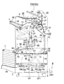
図2は画像形成装置に、後処理装置を接続した場合の説明図である。 FIG. 2 is an explanatory diagram when a post-processing device is connected to the image forming apparatus.
図2及び図1において、画像形成装置Aは記録材に画像を形成する画像形成装置本体Bを有し、用紙3に対して後処理を行う場合は後処理装置FSを接続している。
2 and 1, the image forming apparatus A has an image forming apparatus main body B that forms an image on a recording material, and a post-processing device FS is connected when post-processing is performed on the
なお、画像形成装置本体Bの上部に原稿を画像読取り手段B1に送り込む自動原稿送り装置DFを接続しても良い。 An automatic document feeder DF that feeds a document to the image reading unit B1 may be connected to the upper part of the image forming apparatus main body B.
[画像形成装置本体]
本欄で本発明の、くるみ製本の選択時に表紙用紙の用紙束接着部に画像形成を行わないことを特徴とする画像形成装置について説明する。
[Image forming device body]
In this column, an image forming apparatus according to the present invention that does not perform image formation on the sheet bundle bonding portion of the cover sheet when case binding is selected will be described.
図示の画像形成装置本体Bは、画像読取り手段B1、画像処理手段B2、画像書込み手段B3、画像形成手段B4、給紙搬送手段B5、定着手段B6、操作表示手段B7、画像データ生成手段B8、とこれらを制御する制御手段CBとを有している。 The illustrated image forming apparatus main body B includes an image reading unit B1, an image processing unit B2, an image writing unit B3, an image forming unit B4, a sheet feeding and conveying unit B5, a fixing unit B6, an operation display unit B7, an image data generating unit B8, And control means CB for controlling them.
画像形成手段B4は、感光体ドラム4A、帯電手段4B、現像手段4C、転写手段4D、分離手段4E、クリーニング手段4F等を有し、給紙搬送手段B5は給紙カセット5A、給紙カセット5B、給紙カセット5C、第1給紙手段5D、第2給紙手段5E、第3給紙手段5F、レジストローラ5G、搬送手段5H、排紙手段5I、自動両面コピー給紙手段(ADU)5Jを有している。
The image forming unit B4 includes a photosensitive drum 4A, a charging
操作表示手段B7は画像形成装置本体Bの上部前面に位置し、起動スイッチ等の各種操作スイッチ、及び、各種情報の表示及び各種情報の入力操作が可能なタッチパネル等を有し、タッチパネルには、装置の状態や警報等を表示する表示画面、オペレータに対し操作を促す指示画面、くるみ製本に係る各種画像形成条件の設定又は選択、使用用紙及び表紙用紙の設定又は選択、くるみ製本に係る後処理条件の設定又は選択等を入力する入力画面、の表示が行われると共に、表示された前記画面に基づき設定、選択された操作内容が制御手段CBに入力される。 The operation display means B7 is located on the upper front surface of the image forming apparatus main body B, and has various operation switches such as a start switch, a touch panel that can display various information and input various information, and the like. Display screen for displaying device status and warnings, instruction screen for prompting the operator to operate, setting or selection of various image forming conditions for case binding, setting or selection of used paper and cover paper, post-processing for case binding An input screen for inputting setting or selection of conditions is displayed, and operation contents set and selected based on the displayed screen are input to the control means CB.
また、画像形成装置本体Bの上部には、自動原稿送り装置DFが搭載されている。 An automatic document feeder DF is mounted on the upper part of the image forming apparatus main body B.
画像形成装置本体Bの図示の左側面の排紙手段5I側(下流側)には、後処理機FSが連結されている。 A post-processing device FS is connected to the paper discharge means 5I side (downstream side) on the left side of the image forming apparatus main body B shown in the figure.
自動原稿送り装置DFの原稿台上に載置された原稿は画像読取り手段B1の光学系により原稿の片面又は両面の画像が読みとられ、光電変換された原稿画像のアナログ信号は、画像処理手段B2においてアナログ処理、A/D変換、シェーディング補正、画像圧縮処理等の処理が行われデジタル画像データとなり、デジタル画像データは画像データ生成手段B8でオペレータにより指定された加工・生成が行われ、生成されたデジタル画像データは画像書込み手段B3に送られる。 The original placed on the original table of the automatic document feeder DF is read on one or both sides of the original by the optical system of the image reading means B1, and the analog signal of the photoelectrically converted original image is the image processing means. In B2, analog processing, A / D conversion, shading correction, image compression processing, and the like are performed to obtain digital image data. The digital image data is processed and generated by the image data generation means B8 and processed by the operator. The digital image data thus sent is sent to the image writing means B3.
画像書込み手段B3においては、半導体レーザからの出力光が画像形成手段B4の感光体ドラム4Aに照射され潜像を形成する。 In the image writing means B3, the output light from the semiconductor laser is irradiated onto the photosensitive drum 4A of the image forming means B4 to form a latent image.
ここで、外部の外部の情報端末PCから通信手段PC1、通信手段CB2を介して画像データ等を受信して画像データ生成手段B8で加工・生成する様にしても良い。 Here, image data or the like may be received from the external information terminal PC via the communication unit PC1 and the communication unit CB2, and processed and generated by the image data generation unit B8.
画像形成手段B4においては、帯電手段4B、現像手段4C等により感光体ドラム4Aの一様帯電、潜像の現像が行われ感光体ドラム4A上にトナー像を形成し、転写手段4D、分離手段4E、クリーニング手段4Fにより、給紙搬送手段B5より給送された用紙3へのトナー像の転写、用紙3の分離、感光体ドラム4Aに残ったトナーのクリーニング等の処理が行われる。
In the image forming unit B4, the charging
給紙搬送手段B5より給送された用紙3は転写手段4Dにより画像が用紙3に転写される。画像を担持した用紙3は、定着手段B6によりトナー像が定着され、排紙手段5Iから下流の後処理装置FSに給紙される。
The image of the
両面に画像形成する場合は、自動両面コピー給紙手段5Jに送り込まれた第1面(おもて)画像の定着済みの用紙3は再び画像形成手段B4において第2面(うら)画像形成、定着後、排紙手段5Iにより排出され、下流の後処理装置FSに給紙される。
In the case of forming images on both sides, the
画像形成装置本体B内に配置された制御手段CBに接続された通信手段CB1と、後処理装置FS内に配置された後処理装置の制御手段CFに接続された通信手段CF1とは、通信回線9により接続され、各種データの送受信や、画像形成に係る制御信号等の送受信を行う。 The communication means CB1 connected to the control means CB arranged in the image forming apparatus main body B and the communication means CF1 connected to the control means CF of the post-processing apparatus arranged in the post-processing apparatus FS are communication lines. 9 is used to transmit / receive various data and control signals related to image formation.
また、制御手段CBに接続された通信手段CB2はインターネットやLANを介して外部の情報端末PC(例えばパーソナルコンピュータ等)の通信手段PC1に接続され、画像データを含む各種データや画像形成に係る制御情報を送受信する。 A communication unit CB2 connected to the control unit CB is connected to a communication unit PC1 of an external information terminal PC (for example, a personal computer) via the Internet or a LAN, and controls various data including image data and image formation. Send and receive information.
以下に本発明の画像形成装置に好適に接続可能な後処理装置について、その1つの形態である糊付けくるみ製本装置を例に取り説明する。 A post-processing apparatus that can be suitably connected to the image forming apparatus of the present invention will be described below by taking a glued case binding apparatus as an example thereof as an example.
なお、糊付けくるみ製本装置とは、図1に示したように、複数の用紙を束状に纏め、用紙束の小口に接着剤を塗布し、表紙用紙をコの字状にくるむことにより、冊子を作成することを特徴とする後処理装置を指す。 As shown in FIG. 1, the gluing case binding apparatus is a booklet that is formed by bundling a plurality of sheets into a bundle, applying an adhesive to the edge of the bundle of sheets, and wrapping the cover sheet in a U-shape. Refers to a post-processing device characterized in that
[糊付けくるみ製本装置]
図3は、糊付けくるみ製本装置FSNを説明する断面図である。
[Glued case binding device]
FIG. 3 is a cross-sectional view illustrating the glued case binding apparatus FSN.
図3及び図1に置いて、後処理装置のFSの1種である糊付けくるみ製本装置FSNは、用紙3及び表紙用紙2又は用紙3を搬送する用紙搬送手段10と、用紙3を固定排紙台24に排出する排紙手段20と、表紙用紙2を供給する表紙供給手段30と、搬送された用紙3を複数枚収容し用紙束とする用紙束収容手段40と、用紙束を搬送する用紙束搬送手段50と、用紙束の小口に糊を塗布する糊塗布手段60と、糊を塗布した用紙束に表紙用紙を貼り付ける表紙貼付手段70と、用紙束に貼り付けた表し用紙を用紙束に沿って折り曲げる表紙折り曲げ手段80と、完成した冊子を排出する冊子排出手段90と、糊付けくるみ製本に係る制御を行う制御手段CFと、画像形成装置と通信を行う通信手段CF1と、を有している。
3 and 1, the glued case binding apparatus FSN, which is a kind of FS of the post-processing apparatus, is a sheet transport unit 10 that transports the
上記用紙搬送手段10〜冊子排出手段90の各手段は、糊付けくるみ製本装置本体内の垂直方向に縦列配置されている。 Each of the sheet conveying means 10 to the booklet discharging means 90 is arranged in a vertical line in the gluing case binding apparatus main body.
〈用紙搬送手段10〉
用紙搬送手段10に導入された用紙3は、入口ローラ11,12に挟持されて搬送され、搬送路切換手段G1によって排紙手段20と用紙束収容手段40に分岐される。
<Paper conveying means 10>
The
〈排紙手段20〉
用紙の排紙が設定されると、搬送路切換手段G1は用紙束収容手段40方向への搬送路を遮断し、排紙手段20方向への搬送路を開放し、用紙3を排紙手段20に搬送する。
<Discharge means 20>
When the paper discharge is set, the conveyance path switching unit G1 blocks the conveyance path in the direction of the sheet
排紙手段20への搬送路を通過する用紙3は、搬送ローラ21,22に挟持されて上方に搬送され、排紙ローラ23によって装置最上部の固定排紙台(サブトレイ)24上に排出、収容される。固定排紙台24上には、画像形成装置本体Bから排出された用紙3を直接受容して、最大約200枚を積載することを可能としている。
The
〈表紙供給手段30〉
表紙供給手段30の給紙皿31内に収容された表紙用紙(以下、表紙と称す)2は、給紙手段32により分離、給送され、搬送ローラ33に挟持され、搬送路切換手段G2によって下方に案内され、搬送ローラ34,35,36に挟持されて、表紙貼付手段70に搬送される。
<Cover Supply Unit 30>
A cover sheet (hereinafter referred to as a cover) 2 accommodated in a
なお、画像形成装置本体Bで画像形成された表紙用紙を用いる場合は、画像形成装置本体Bから給紙された表紙用紙を入口ローラ11,12、搬送路切換手段G1、搬送路切換手段G2、搬送ローラ45を経て一旦用紙束収容手段40側に搬送し、その後搬送ローラ45を逆転させ表紙用紙を搬送路切換手段G3、搬送ローラ33、給紙手段32を経て表紙供給手段30に搬送し、給紙皿31内に収容する。そして、表紙貼付時に上記したようにして表紙貼付手段70に搬送する。
In the case of using a cover sheet on which an image is formed by the image forming apparatus main body B, the cover sheet fed from the image forming apparatus main body B is used as the entrance rollers 11 and 12, the transport path switching means G1, the transport path switching means G2, The paper is once transported to the sheet bundle housing means 40 side through the
〈用紙束収容手段40〉
搬送路切換手段G1,G2によって用紙搬送方向下流側の用紙束収容手段40側に搬送された用紙3は、搬送ローラ41に挟持されて用紙束収容手段40の所定位置に収容され順次積載されて、所定枚数の用紙3から成る用紙束4が形成される。
<Paper bundle accommodating means 40>
The
用紙束収容手段40は、傾斜配置された用紙載置台42、揺動可能な用紙後端位置決め部材43、用紙幅方向を位置決めする用紙幅整合部材44等を有している。 The sheet bundle accommodating means 40 includes a sheet placing table 42 that is inclined, a swingable sheet rear end positioning member 43, a sheet width aligning member 44 that positions the sheet width direction, and the like.
〈用紙束搬送手段50〉
用紙束収容手段40の用紙載置台42上に積載された用紙束4は、図示しない押し出し手段により斜め下方に搬送される。その後、用紙束4は用紙束搬送手段50の把持手段51によって把持され、用紙束4を把持したまま、用紙束4に糊塗布処理をする面を下側になるように旋回されて、所定位置に停止される。
<Paper bundle conveying means 50>
The
〈糊塗布手段60〉
糊塗布手段60は、糊塗布部材(塗布ローラとも称す)61と、塗布ローラ61の回転手段62と、糊を収容する糊容器63と、移動体64と、移動体64を往復動させる移動手段、とを有している。移動体64は、塗布ローラ61、回転手段62、糊容器63を支持して、用紙束4の小口4bに沿って(図示紙面表裏方向)に移動可能である。
<Glue application means 60>
The glue applying means 60 includes a glue applying member (also referred to as an application roller) 61, a rotating
なお、糊塗布部材61は塗布ローラに限定されるものではなく、糊塗布ノズル、両面粘着テープ等も適用可能である。
The
〈表紙貼付手段70〉
表紙貼付手段70は、表紙供給手段30から供給された表紙用紙2を受容して搬送し、例えば表紙用紙の幅手方向略中央が用紙束4の小口の中央部と一致する所定位置に停止させる搬送ベルト71,72と、表紙用紙2を用紙束4の糊塗布面6に圧接させる加圧部材73と、搬送ベルト71,72と加圧部材73を支持する移動筐体74と、移動筐体74を垂直上下方向に移動可能にする昇降手段75とを有している。
<Covering means 70>
The cover sticking means 70 receives and transports the
昇降手段75は、支持台751に支持され、支軸752によって回転自在に枢支されX字型に交差する2本のアーム753,754と、駆動源に接続して支持台751の長溝部755に沿って水平移動可能な可動軸756と、移動筐体74を支持するコロ757と、を有している。
The lifting / lowering means 75 is supported by a
可動軸756を移動させる事により、2本のアーム753,754の上端部が上昇して、移動筐体74を上方位置に移動させる。この上昇位置(図3の破線で示す位置)において、加圧部材73上に載置された表紙用紙2の中央部は、用紙束4aの糊塗布面6に圧接して接着される。
By moving the
〈表紙用紙断裁手段76〉
移動筐体74の図示右方に配置された表紙用紙断裁手段76は、必要に応じて不図示のカッタにより表紙用紙2の搬送方向長さを所定長に断裁する。
<Cover sheet cutting means 76>
A cover sheet cutting means 76 arranged on the right side of the
〈表紙折り曲げ手段80〉
表紙貼付手段70の上部には、表紙折り曲げ手段80が装備されている。表紙り曲げ手段80は、左右対称な一対の折り曲げ部材81を有する。折り曲げ部材81は用紙束4の厚さ方向に移動可能で、かつ上下方向に移動可能である。
折り曲げ部材8は用紙束4の糊塗布面6の側縁に沿って表紙用紙2を折り曲げ、用紙束4の表裏面にそれぞれ表紙用紙2を重ね合わせ、表表紙と裏表紙とを形成する。
<Cover folding means 80>
A cover folding means 80 is provided above the cover sticking means 70. The cover bending means 80 includes a pair of
The folding
〈冊子断裁手段〉
2本の排出ベルト91,92の上流(図示右側)に冊子1の小口4b側を断裁する不図示の冊子断裁手段が配設されている。
<Booklet cutting means>
A booklet cutting means (not shown) for cutting the
糊塗布された用紙束4の背部4aに表紙用紙2が貼付されておもて表紙とうら表紙とを形成した冊子1は小口側を冊子断裁手段に向けて搬送され、切断予定位置が冊子断裁手段のカッタに来た時点で停止し、カッタにより冊子1が切断予定位置に沿って断裁され所定の寸法の冊子が形成される。
The
〈冊子排出手段〉
糊塗布された用紙束4の背部に表紙用紙2が貼付されておもて表紙とうら表紙とを形成した冊子1は、冊子排出手段90の2本の排出ベルト91,92により排出開口93から装置外に排出され、昇降排紙台94上に載置され、順次積載される。昇降排紙台94上に冊子1が排出、積載されると、昇降排紙台94は順次下降する。
<Booklet discharge method>
The
なお、くるみ製本装置FSNの表紙供給手段30の下流に表紙を2つ折り、3つ折り等にする折り手段を設けて、必要に応じて表紙のおもて表紙或いはうら表紙に相当する部分を2つ折り、3つ折り等にしても良い。
以上、糊付けくるみ製本について述べてきたが、糊塗布手段60と表紙貼付手段70とを、用紙束を表紙用紙でくるみステープル止めするステープル手段に置き換えステープルくるみ包装を行っても良い。
It should be noted that folding means for folding the cover into two, three, etc. is provided downstream of the cover supply means 30 of the case binding apparatus FSN, and the portion corresponding to the front cover or back cover of the cover is folded into two as required. It may be tri-folded.
As described above, the glue case binding has been described. However, the glue application means 60 and the cover sheet attaching means 70 may be replaced with a staple means for wrapping and stapling a sheet bundle with cover sheets to perform staple case packaging.
以下に、糊付けくるみ製本の選択時に表紙うら面(用紙束接着面)の用紙束接着部に画像形成を行わないことを特徴とする画像形成について説明する。 In the following, image formation is described, in which image formation is not performed on the sheet bundle adhesion portion of the back cover surface (sheet bundle adhesion surface) when selecting glued case binding.
図4は画像形成装置本体の制御ブロック図である。 FIG. 4 is a control block diagram of the image forming apparatus main body.
画像形成装置本体Bは、画像読取り手段B1、画像処理手段B2、画像書込み手段B3、画像形成手段B4、給紙搬送手段B5、定着手段B6、及び自動原稿送り装置DFを、入出力インターフェイス手段I/Oを介し制御する制御手段CBと、オペレータから入力された各種操作情報を制御手段CBに入力し、制御手段CBから出力された各種表示情報に基づき表示を行う操作表示手段B7と、後処理装置である糊付けくるみ製本装置FSNの制御手段CFに接続された通信手段CF1と通信回線9を介して通信を行う通信手段CB1と、外部の情報端末PCの制御手段CPに接続された通信手段PC1とインターネットやLANを介して通信を行う通信手段CB2と、画像形成装置本体Bの上述した画像読取り手段B1〜自動原稿送り装置DFを制御する制御プログラム及び糊付けくるみ製本装置FSNと外部の情報端末PCとの糊付けくるみ製本に係る情報を送受信する方法を記述したプログラムを予め記憶されたROM・M1と、各種情報を一時的に記憶するバッテリーバックアップされたRAM・M2とを有している。 The image forming apparatus main body B includes an image reading unit B1, an image processing unit B2, an image writing unit B3, an image forming unit B4, a sheet feeding / conveying unit B5, a fixing unit B6, and an automatic document feeder DF. Control means CB controlled via / O, operation display means B7 for inputting various operation information input from the operator to the control means CB, and displaying based on various display information output from the control means CB, post-processing The communication means CB1 for communicating with the communication means CF1 connected to the control means CF of the glued case binding apparatus FSN, which is the apparatus, via the communication line 9, and the communication means PC1 connected to the control means CP of the external information terminal PC A communication unit CB2 that communicates with the Internet and a LAN, and the image reading unit B1 to the automatic document feeder described above of the image forming apparatus main body B. A control program for controlling the DF and a ROM / M1 preliminarily storing a program describing a method for transmitting and receiving information relating to glue case binding with an external information terminal PC between the glue case and book binding device FSN and various information temporarily It has a battery-backed RAM M2 to be stored.
ROM・M1には予め各種の用紙の厚さ情報としての後述する用紙の種類に対する用紙の厚さテーブルや、後述の各種画面の画像情報等が記憶されている。 The ROM M1 stores in advance a sheet thickness table for various sheet types, which will be described later, and image information for various screens, which will be described later, as various sheet thickness information.
用紙の種類に対する用紙の厚さテーブルの内容すなわち用紙の種類に対する用紙の厚さ情報は操作表示手段B7で用紙の厚さ追加・変更モードの設定或いはROMの交換により追加変更が可能となっている。 The contents of the sheet thickness table with respect to the sheet type, that is, the sheet thickness information with respect to the sheet type, can be additionally changed by setting the sheet thickness addition / change mode or replacing the ROM in the operation display means B7. .
RAM・M2には後述する選択された実行機能情報、応用機能情報、各種画像データ、各種演算結果が記憶される。 The RAM M2 stores selected execution function information, applied function information, various image data, and various calculation results, which will be described later.
また、各給紙カセットに対する用紙の厚さ・寸法テーブルの内容すなわち給紙カセットに対する用紙の種類、厚さ、サイズ情報はカセット用紙の追加・変更モードにすることにより操作表示手段B7で追加変更が可能となっている。 Further, the contents of the paper thickness / dimension table for each paper feed cassette, that is, the paper type, thickness, and size information for the paper feed cassette can be added or changed by the operation display means B7 by setting the cassette paper addition / change mode. It is possible.
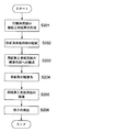
図5は画像形成装置本体の糊付けくるみ製本に係るフロー図である。 FIG. 5 is a flowchart according to glued case binding of the image forming apparatus main body.
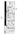
図6は操作表示手段に表示するカセット/用紙入力画面の図である。 FIG. 6 is a diagram of a cassette / paper input screen displayed on the operation display means.
図7は操作表示手段に表示する基本画面の図である。 FIG. 7 is a diagram of a basic screen displayed on the operation display means.
図8は操作表示手段に表示する応用機能選択画面の図である。 FIG. 8 is a diagram of an application function selection screen displayed on the operation display means.
図9は操作表示手段に表示する後処理機能選択画面の図である。 FIG. 9 is a diagram of a post-processing function selection screen displayed on the operation display means.
図10は操作表示手段に表示する表紙に用いる用紙の選択画面の図である。 FIG. 10 is a diagram of a paper selection screen used for the cover page displayed on the operation display means.
以下のフロー図に記載のプログラムはROM・M1に記憶されており、RAM・M2に記憶され、制御手段CBにより実行される。 The program described in the following flow chart is stored in the ROM · M1, stored in the RAM · M2, and executed by the control means CB.
準備作業。オペレータは例えば用紙を給紙カセットに収納時に、各給紙カセットに収納されている用紙の種類及びサイズを入力し、入力内容が記憶させる。 preparation work. For example, when the sheet is stored in a sheet cassette, the operator inputs the type and size of the sheet stored in each sheet cassette and stores the input contents.
オペレータは各給紙カセット5A〜5Cに収納されている用紙の種類及びサイズを入力する給紙カセット/用紙入力画面B71(図6)を操作表示手段B7に表示させ、各給紙カセットに収納されている用紙(表紙用紙)の種類及びサイズを入力し、この内容がRAM・M2に記憶される。 The operator displays on the operation display means B7 a paper cassette / paper input screen B71 (FIG. 6) for inputting the type and size of paper stored in each of the paper cassettes 5A to 5C, and is stored in each paper cassette. The type and size of the current paper (cover paper) are input, and the contents are stored in the RAM M2.
具体的には、給紙カセット指定領域B71aで設定する給紙カセットを選択し、選択した給紙カセットに収納した用紙に合わせて、サイズ指定領域B71bで用紙のサイズを選択し、次いで紙種指定領域B71cで紙種を選択する。選択された給紙カセットに対応する用紙サイズと紙種情報がRAM・M2に記憶される。 Specifically, the paper cassette to be set is selected in the paper cassette designation area B71a, the paper size is selected in the size designation area B71b according to the paper stored in the selected paper cassette, and the paper type designation is then performed. The paper type is selected in the area B71c. The paper size and paper type information corresponding to the selected paper feed cassette are stored in the RAM M2.
なお例えばA3ノビ用紙とは、例えばA4用紙を内容とする冊子とするときに、小口を断裁することを前提に少なくとも用紙の幅手方向の寸法がA3より若干長くなっている用紙を指す。 Note that, for example, A3 Nobi paper refers to paper having at least the width dimension of the paper slightly longer than A3 on the premise that the front edge is cut when the booklet is A4 paper.
図示ではオペレータにより第1給紙ユニットが選択され、次いで第1給紙ユニットの用紙としてはA4サイズの普通紙が選択されたことを示している。 In the drawing, it is shown that the first paper feed unit is selected by the operator, and then A4 size plain paper is selected as the paper of the first paper feed unit.
以下、第1給紙カセットはA4サイズの普通紙が選択され、第3給紙カセットはA3ノビサイズの普通紙が選択さたもの、すなわち第1給紙カセットにはA4サイズの普通紙が収納され、第3給紙カセットにはA3ノビサイズの普通紙が収納されているものとして説明する。 Hereinafter, A4 size plain paper is selected as the first paper feed cassette, and A3 size plain paper is selected as the third paper feed cassette, that is, A4 size plain paper is stored in the first paper feed cassette. In the following description, it is assumed that the third paper feed cassette contains plain paper of A3 size.
機能の選択工程。操作表示手段に基本画面を表示させ、実行させる機能の選択を促す。(ステップS101)
具体的には、ROM・M1に予め記憶されている基本画面B72(図7)の画面データを読み出し、操作表示手段B7に機能設定画面B72aを含む基本画面B72を表示させ、オペレータに実行させる機能の選択を促す。
Function selection process. A basic screen is displayed on the operation display means to prompt selection of a function to be executed. (Step S101)
Specifically, the screen data of the basic screen B72 (FIG. 7) stored in advance in the ROM M1 is read, the basic screen B72 including the function setting screen B72a is displayed on the operation display means B7, and the function executed by the operator. Encourage selection.
そして、選択された実行させる機能をRAM・M2に記憶させる。 Then, the selected function to be executed is stored in the RAM M2.
機能設定部分B72aから、応用機能(B72b)が選択されたものとして以下説明する。 The following description assumes that the applied function (B72b) is selected from the function setting portion B72a.
応用機能の選択工程。操作表示手段に応用機能選択画面を表示させ、実行させる応用機能の選択を促す。(ステップS102)
具体的には、ステップS101で選択された応用機能に応じ、ROM・M1に予め記憶されている応用機能のメニュー画面B73(図8)の画面データを読み出し、操作表示手段B7に応用機能のメニュー画面B73を表示させ、オペレータに実行させる応用機能の選択を促す。
Application function selection process. An application function selection screen is displayed on the operation display means to prompt selection of an application function to be executed. (Step S102)
Specifically, in accordance with the application function selected in step S101, the screen data of the application function menu screen B73 (FIG. 8) stored in advance in the ROM M1 is read, and the application function menu is displayed in the operation display means B7. A screen B73 is displayed to prompt the operator to select an application function to be executed.
そして、選択された応用機能をRAM・M2に記憶させる。 Then, the selected application function is stored in the RAM M2.
応用機能のメニュー画面B73から、後処理機能(B73a)が選択されたものとして以下説明する。 The following description assumes that the post-processing function (B73a) is selected from the application function menu screen B73.
なお、直接ステップS102からスタートするようにしても良い。 Note that the process may start directly from step S102.
後処理機能の選択工程。操作表示手段に後処理機能選択画面を表示させ、実行させる後処理機能の選択を促す。(ステップS103)
具体的にはステップS102で選択された後処理機能に応じ、ROM・M1に予め記憶されている後処理機能のメニュー画面B74(図9)の画面データを読み出し、操作表示手段B7に後処理機能のメニュー画面B74を表示させ、オペレータに実行させる後処理機能の選択を促す。
Post-processing function selection process. A post-processing function selection screen is displayed on the operation display means to prompt selection of a post-processing function to be executed. (Step S103)
Specifically, in accordance with the post-processing function selected in step S102, the screen data of the post-processing function menu screen B74 (FIG. 9) stored in advance in the ROM M1 is read, and the post-processing function is displayed in the operation display means B7. Menu screen B74 is displayed to prompt the operator to select a post-processing function to be executed.
そして、選択された後処理機能をRAM・M2に記憶させる。 Then, the selected post-processing function is stored in the RAM M2.
後処理機能のメニュー画面B74から、糊付けくるみ処理(B74a)が選択されたものとして以下説明する。 The following description will be made assuming that the gluing case processing (B74a) is selected from the menu screen B74 of the post-processing function.
使用用紙と使用表紙の選択工程。操作表示手段に用紙及び表紙の選択画面を表示させ、使用する用紙と表紙の選択を促す。(ステップS104)
具体的には、選択された糊付けくるみ処理機能に応じ、ROM・M1に予め記憶されている用紙及び表紙の使用給紙カセット選択画面B75(図10)の画面データを読み出し、操作表示手段B7に用紙及び表紙の使用給紙カセット選択画面B75を表示させ、オペレータに用紙及び表紙用紙として使用する給紙カセットの選択を促す。
Selection process of used paper and used cover. A sheet and cover selection screen is displayed on the operation display means to prompt the user to select a sheet and cover to be used. (Step S104)
Specifically, in accordance with the selected gluing case processing function, the screen data of the paper and cover used paper cassette selection screen B75 (FIG. 10) pre-stored in the ROM M1 is read and displayed on the operation display means B7. The paper and cover used paper feed cassette selection screen B75 is displayed to prompt the operator to select a paper feed cassette to be used as paper and cover paper.
そして、選択された用紙及び表紙用紙の給紙カセットをRAM・M2に記憶させる。 Then, the selected sheet and cover sheet feeding cassette are stored in the RAM M2.
図示は用紙に第1給紙カセットから給紙し、表紙には第3給紙カセットから給紙する選択が示されている。 In the figure, the sheet is fed from the first sheet cassette and the cover is selected to feed from the third sheet cassette.
用紙及び表紙の使用給紙カセット選択画面B75から、用紙は第1給紙カセット即ちA4サイズの普通紙、表紙用紙は第3給紙カセット即ちA3ノビサイズの普通紙が選択されたものとして以下説明する。 In the following description, it is assumed that the first paper cassette, that is, A4 size plain paper is selected from the paper and cover used paper feed cassette selection screen B75, and the third paper cassette, that is, A3 novi size plain paper is selected as the cover paper. .
ここで、例えば第1給紙ユニットがA4で普通紙であることは、準備作業でRAM・M2に記憶された各給紙カセットに収納されている用紙の種類及びサイズ情報を読み出すことにより表示することができる。 Here, for example, the fact that the first paper feed unit is A4 and plain paper is displayed by reading out the type and size information of the paper stored in each paper feed cassette stored in the RAM M2 in the preparatory work. be able to.
用紙の画像形成工程。情報端末PCから、或いは画像読取り手段B1からプリントすべき画像情報を取得し、取得した画像情報を用紙に順次画像形成する。そして画像形成した用紙の枚数をカウントする。(ステップS105)
具体的には情報端末PCから画像情報(文字、絵等の画像を含む)を取得する場合は、(1)通信手段CB1、インターネット、通信手段PC1等を介して制御手段CBから制御手段CPにプリントすべき画像情報の送信依頼を行い、(2)送信依頼に応じて通信手段PC1、インターネット、通信手段CB1等を介して制御手段CPから送信された画像情報を受信し、(3)受信した画像情報を一旦RAM・M2に記憶させ、(4)記憶した画像情報を読み出して潜像を形成し、潜像を現像し、ステップS104で選択され、RAM・M2に記憶された用紙に係る使用給紙カセット情報に基づき給紙された用紙に転写・定着することにより画像形成する。
Paper image formation process. Image information to be printed is acquired from the information terminal PC or from the image reading unit B1, and the acquired image information is sequentially formed on a sheet. Then, the number of sheets on which images are formed is counted. (Step S105)
Specifically, when acquiring image information (including images such as characters and pictures) from the information terminal PC, (1) the control means CB to the control means CP via the communication means CB1, the Internet, the communication means PC1, etc. (2) Receive image information transmitted from the control means CP via the communication means PC1, the Internet, the communication means CB1, etc. in response to the transmission request, and (3) receive the image information to be printed. The image information is temporarily stored in the RAM M2, and (4) the stored image information is read to form a latent image, the latent image is developed, and the use related to the sheet selected in step S104 and stored in the RAM M2 An image is formed by transferring and fixing to a sheet fed based on the sheet cassette information.
また、画像読取り手段B1からプリントすべき画像情報を取得する場合は、(1)原稿を順次搬送させ、搬送する用紙の画像を画像読取り手段B1で順次読み取り、同様にして画像形成する。 Further, when acquiring image information to be printed from the image reading unit B1, (1) sequentially transport the original, sequentially read the images on the transported paper by the image reading unit B1, and form an image in the same manner.
そして、いずれの方法の場合も画像形成を行った用紙の枚数を不図示のカウンタによりカウントする。また、給紙される用紙の枚数をカウントする不図示のカウンタによりカウントするようにしても良い。 In either method, the number of sheets on which image formation has been performed is counted by a counter (not shown). Further, it may be counted by a counter (not shown) that counts the number of sheets fed.
カウンタのカウント値がn1枚であったものとして以下説明する。 The following description will be made assuming that the count value of the counter is n 1 sheets.
用紙束の厚さ演算工程。用紙束の厚さを演算する。(ステップS106)
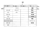
図11は、用紙の種類に対する用紙の厚さテーブル及び用紙のサイズに対する用紙寸法テーブルの説明図である。
Sheet bundle thickness calculation process. Calculate the thickness of the stack of paper. (Step S106)
FIG. 11 is an explanatory diagram of a paper thickness table for paper types and a paper dimension table for paper sizes.
具体的には、ステップS104でRAM・M2に記憶された用紙及び表紙用紙として給紙する給紙カセット情報(用紙の紙種情報)、及びROM・M1に予め記憶されている用紙の種類に対する用紙の厚さテーブルB76(図11)の画像データを読み出し、給紙カセット情報(用紙の紙種情報)に対応する用紙の厚さを取得する。 Specifically, the paper corresponding to the paper type stored in the RAM M2 in step S104 and the paper cassette information (paper type information) supplied as the cover paper and the paper type stored in advance in the ROM M1 The image data of the thickness table B76 (FIG. 11) is read out, and the paper thickness corresponding to the paper cassette information (paper type information) is acquired.
ステップS103で普通紙が選択されているので、用紙の種類に対する用紙の厚さテーブルB76から普通紙に対応する厚さd4mmを読み出し、用紙の厚さにステップS104で取得した用紙の枚数n1の積を算出する演算を行い用紙束の厚さDを算出し、演算結果をRAM・M2に記憶させる。 Since plain paper is selected in step S103, the thickness d 4 mm corresponding to the plain paper is read from the paper thickness table B76 for the paper type, and the number n of sheets obtained in step S104 is obtained as the paper thickness. A calculation for calculating the product of 1 is performed to calculate the thickness D of the sheet bundle, and the calculation result is stored in the RAM M2.
D=d4×n1 (mm)
表紙の印刷画像データの取得工程。通信手段を介し情報端末等から表紙に印刷するおもて面及びうら面の画像データを取得する。(ステップS107)
通信手段CB1、通信手段PC1等を介し情報端末PC等から表紙に印刷するおもて面及びうら面の画像データと、うら面の画像データをどのように加工するかの情報を取得する。
D = d 4 × n 1 (mm)
Acquisition process of print image data on the cover. The image data of the front surface and the back surface to be printed on the cover is obtained from the information terminal or the like via the communication means. (Step S107)
Information on how to process the image data on the front surface and the back surface and the image data on the back surface is acquired from the information terminal PC or the like via the communication unit CB1, the communication unit PC1, and the like.
具体的には、ステップS105で用紙に印刷すべき画像を取得した方法と同様にして、表紙のおもて面とうら面に印刷する画像データ、及び、うら面の画像データのうち背2Cに当たる部分の画像データを削除するのか或いは、うら面の画像データを縮小し、背2Cに当たる部分に印刷を行わせない様に2分割するのかの情報を外部の情報端末PC等から通信手段PC1、通信手段CB2を介し送信させる。そして受信した画像データをRAM・M2に記憶させる。
Specifically, in the same manner as the method for obtaining the image to be printed on the paper in step S105, the image data to be printed on the front and back surfaces of the cover and the back 2C among the image data on the back surface. Information on whether to delete the image data of the portion or to reduce the image data of the back surface and divide into two so that the portion corresponding to the
図12は、表紙用紙のうら面に印刷する生成印刷画像データの概念図である。 FIG. 12 is a conceptual diagram of generated print image data to be printed on the back side of the cover sheet.
図12(a)はステップS107でRAM・M2に記憶された表紙用紙2のうら面のおもて表紙2A・うら表紙2Bの画像データに基づく未加工印刷領域2Aa、2Baを示している。
FIG. 12A shows the unprocessed print areas 2Aa and 2Ba based on the image data of the
図12(b)はステップS107でRAM・M2に記憶された画像データに対し、背2Cに当たる部分の画像データを削除した画像データに基づく削除印刷領域2Ab、2Bbを示している。 FIG. 12B shows deleted print areas 2Ab and 2Bb based on the image data obtained by deleting the image data corresponding to the back 2C from the image data stored in the RAM M2 in step S107.
図12(c)はステップS107でRAM・M2に記憶された、おもて表紙2A及びうら表紙2Bのうら面に対応する画像データに対し、おもて表紙とうら表紙に対応する画像データをそれぞれ縮尺し、背2Cに当たる部分の画像データをなくした画像データに基づく縮尺印刷領域2Ac、2Bcを示している。
FIG. 12C shows the image data corresponding to the front cover and the back cover of the
なお、W1はおもて表紙2A及びうら表紙2Bの幅寸法、W2は背2Cの幅寸法、Wは表紙用紙の幅寸法を指す。
W 1 indicates the width dimension of the
図12(d)は上記に加え、折り畳み可能な表紙用紙を用紙束に接着する場合の説明図で、例えば表紙用紙は、おもて表紙2A幅と背2C幅とうら表紙2B幅の2倍の和の幅寸法を有し、うら表紙2B’は一点鎖線部で折り曲げられ、冊子形態となった時背2Cに接着された用紙束(不図示)とうら表紙2Bとの間に挟み込まれるように折り畳まれる。おもて表紙2A、うら表紙2B、2B’は、それぞれ縮尺印刷領域2Ac、2Bc、2Bc’を有している。
In addition to the above, FIG. 12D is an explanatory diagram when a foldable cover sheet is bonded to a sheet bundle. For example, the cover sheet has a
表紙用紙の印刷画像生成工程。画像データ生成手段でステップS107で取得したうら面の画像データのうち、背2Cに当たる部分に印刷を行わせない様に印刷する画像データを生成する。(ステップS108)
本工程は用紙束の厚さを把握後すなわち少なくとも用紙の画像形成枚数把握後に行う。このため、全ての用紙の画像形成後に行う。
Print image generation process for cover paper. Image data generating means generates image data to be printed so that printing is not performed on the portion corresponding to the back 2C of the back surface image data acquired in step S107. (Step S108)
This process is performed after the thickness of the sheet bundle is ascertained, that is, at least after the number of sheets on which images are formed. For this reason, it is performed after image formation on all sheets.
ステップS107で取得しRAM・M2に記憶されたおもて面の画像データは加工をせずそのままおもて面印刷画像データとしRAM・M2に記憶させ、外部の情報端末PCからのうら面の画像データは背部の画像データを削除するのか或いは縮小し2分割するのかの情報に基づき、下記の加工を行う。 The image data of the front surface acquired in step S107 and stored in the RAM • M2 is stored in the RAM • M2 as surface print image data as it is without being processed, and the back surface image from the external information terminal PC is stored. The image data is subjected to the following processing based on information on whether the back image data is deleted or reduced and divided into two.
(1)削除する場合は、画像データ生成手段B8で、図12(b)に図示した様にうら面の画像データのうち背2Cに当たる部分の画像データを削除し、背2Cの部分は印刷が行われない様に印刷禁止の制御データを挿入した背部削除うら面印刷画像データを生成し、RAM・M2に記憶させる。 (1) When deleting, the image data generating means B8 deletes the image data corresponding to the back 2C from the back side image data as shown in FIG. 12B, and the back 2C portion is printed. The back side deleted back surface print image data into which the print prohibition control data is inserted is generated so as not to be performed, and is stored in the RAM M2.
これにより、背部紙うら面にトナー画像が形成されず用紙束と表紙の接着が確実となり、且つトナーの消費量が削減でき環境に優しい冊子が提供可能となる。 As a result, a toner image is not formed on the back side of the back paper, the adhesion between the sheet bundle and the cover is ensured, the amount of toner consumption can be reduced, and an environmentally friendly booklet can be provided.
(2)うら面の画像データを縮小し、2分割する場合は、画像データ生成手段B8で、図12(c)に図示した様にうら面の画像データを縮尺率=2×W1/(2×W1+W2)に縮尺し、縮尺したうら面の画像データをおもて表紙側とうら表紙側に分割し、分割した間すなわち背2Cの部分は印刷が行われない様に印刷禁止の制御データを挿入した縮小うら面印刷画像データを生成し、RAM・M2に記憶させる。
(2) When the image data on the back surface is reduced and divided into two, the image data generating means B8 converts the image data on the back surface as shown in FIG. 12 (c) at a scale ratio = 2 × W 1 / ( 2 × W 1 + W 2 ), the scaled back side image data is divided into the front cover side and the back cover side, and printing is prohibited so that the portion of the
なお、うら面の全画像データのうち背2Cのうら面に当たる部分の画像データを削除するのか或いは、うら面の全画像データを縮小し、背2Cに当たる部分に印刷を行わせない様に2分割するのかの判断は、操作表示手段B7に両者のいずれを実行させるかの選択キーを表示させ、選択結果に基づいて行わせても良い。
In addition, the image data corresponding to the back surface of the
これにより、うら面の全画像データが画像形成可能となると共に、背部紙うら面にトナー画像が形成されず用紙束と表紙の接着が確実となり、且つトナーの消費量が削減でき環境に優しい冊子が提供可能となる。 This makes it possible to form all the image data on the back side, as well as to form a toner image on the back side of the back paper, ensuring the adhesion between the sheet bundle and the cover, and reducing the amount of toner consumed, making it an environmentally friendly booklet. Can be provided.
(3)図12(d)に図示した様に、折り畳み可能な表紙用紙を用いてくるみ製本を行う場合は、上述した略表紙用紙中央に用紙束を接着する場合に比べ用紙束を接着する位置(即ち背の位置)が中央に対してずれるため、折り曲げる回数或いは折り曲げる寸法に応じて、画像データ生成手段B8により、うら面の画像データのうち背2Cに当たる部分に対応する画像データを削除し、背2Cの部分は印刷が行われない様に印刷禁止の制御データを挿入した背部削除うら面印刷画像データを生成する。また、うら面の画像データを縮尺率=3×W1/(3×W1+W2)に縮尺し、縮尺したうら面の画像データをおもて表紙とうら表紙に分割し、分割した間すなわち背2Cの部分は印刷が行われない様に印刷禁止の制御データを挿入した縮小うら面印刷画像データを生成し、RAM・M2に記憶させる。
(3) As shown in FIG. 12D, when case binding is performed using a foldable cover sheet, the position where the sheet bundle is bonded as compared to the case where the sheet bundle is bonded to the above-described approximate cover sheet center. (That is, the position of the back) is shifted from the center, so that the image data generation means B8 deletes the image data corresponding to the portion corresponding to the
これにより、折り畳み可能な表紙用紙を用いてくるみ製本を行う場合でも背表紙うら面にトナー画像が形成されず用紙束と表紙の接着が確実となると共にトナーの消費量が削減でき環境に優しい冊子が提供可能となる。 As a result, even when performing case binding using foldable cover sheets, a toner image is not formed on the back side of the back cover, so that adhesion between the sheet bundle and the cover is ensured and toner consumption can be reduced, which is environmentally friendly. Can be provided.
また、他の実施の形態として、画像データ生成手段B8で例えば削除してしまう背部に印刷する画像データをおもて表紙又はうら表紙に印刷する画像データに付加し、オーバーレイ画像データを生成し、RAM・M2に記憶させても良い。 Further, as another embodiment, image data to be printed on the back portion that is deleted, for example, by the image data generation means B8 is added to the image data to be printed on the front cover or back cover, and overlay image data is generated, You may memorize | store in RAM * M2.
これにより背部の画像データを削除してもおもて又はうら表紙にオーバーレイ印刷を行うことが可能となり、接着により見えなくなってしまうことが防止することを可能とできる。 As a result, even if the back image data is deleted, overlay printing can be performed on the front cover or the back cover, and it can be prevented from becoming invisible due to adhesion.
表紙用紙の画像形成工程。表紙用紙のおもて面及びうら面に画像形成を行う。(ステップS109)
具体的には、表紙用紙のおもて面及びうら面にステップS108で生成しRAM・M2に記憶させたおもて面印刷画像データを読み出して画像書込み手段B3に送り、感光体ドラム4Aに潜像を形成し、現像を行い、ステップS104で記憶された表紙用紙を給紙する給紙カセット(例えば第3給紙カセット)から給紙される表紙用紙に転写し、定着を行い、おもて面に画像形成を行なう。
Cover sheet image forming process. Image formation is performed on the front and back surfaces of the cover sheet. (Step S109)
Specifically, the front side print image data generated in step S108 on the front and back sides of the cover sheet and stored in the RAM M2 is read out and sent to the image writing means B3, and is supplied to the photosensitive drum 4A. A latent image is formed, developed, transferred to a cover sheet fed from a sheet feeding cassette (for example, a third sheet feeding cassette) that feeds the cover sheet stored in step S104, fixed, To form an image on the surface.
次いで、設定に応じ、ステップS107でRAM・M2に記憶された背部削除うら面印刷画像データ或いは縮小うら面印刷画像データを読み出して、画像書込み手段B3に送り、感光体ドラム4Aに潜像を形成し、画像形成手段B4で現像し、表裏を反転して給紙されたうら面に画像形成を行う。 Next, in accordance with the setting, the back deleted back side print image data or the reduced back side print image data stored in the RAM M2 in step S107 is read and sent to the image writing means B3 to form a latent image on the photosensitive drum 4A. Then, development is performed by the image forming unit B4, and the image is formed on the back side of the paper that has been fed upside down.
そして、おもて面うら面に画像形成を行った表紙用紙を後処理装置に給紙する。 Then, the cover sheet on which the image is formed on the front side is fed to the post-processing device.
なお、上記表紙用紙の印刷画像生成工程及び表紙用紙の印刷工程において、表紙用紙の印刷画像生成はオフラインの独立した画像形成装置にステップS108で説明したと同様な方法でおもて面印刷画像データ、背部削除うら面印刷画像データ、縮小うら面印刷画像データを生成させる様にしても良く、表紙用紙の印刷は、オフラインの独立した画像形成装置で上述(ステップS109)したと同様な方法でおもて面の印刷、うら面の画像形成を行っても良い。 In the cover sheet print image generation process and the cover sheet print process, the front cover print image data is generated in the same manner as described in step S108 in an off-line independent image forming apparatus. The back-side deleted back side print image data and the reduced back side print image data may be generated, and the cover sheet is printed in the same manner as described above (step S109) by the offline independent image forming apparatus. Printing on the front side and image formation on the back side may be performed.
この場合は、後述する後処理(糊付けくるみ製本)を行う時、印刷が完了した表紙用紙は後処理装置の表紙供給手段30にオペレータにより手差しされる。 In this case, when post-processing (gluing case binding) described later is performed, the cover sheet that has been printed is manually fed to the cover supply means 30 of the post-processing apparatus by the operator.
以下、後処理装置の糊付けくるみ製本に係る工程について図13、5、3を参照して説明する。 In the following, a process related to glued case binding of the post-processing apparatus will be described with reference to FIGS.
図13は後処理装置の糊付けくるみ製本に係るフロー図である。 FIG. 13 is a flowchart according to glued case binding of the post-processing apparatus.
用紙の後処理装置への給紙工程。ステップS105で画像形成を行った用紙がそのまま後処理装置に給紙される。(ステップS201)
具体的には、ステップS105で画像形成を行ない画像形成装置から給紙された用紙は入口ローラ11,12、搬送ローラ45、搬送ローラ41を経て用紙束収容手段40の用紙載置台42に積載・収納され、用紙束が形成される。
Paper feeding process to the paper post-processing device. The sheet on which the image is formed in step S105 is fed to the post-processing apparatus as it is. (Step S201)
Specifically, the sheet formed by the image forming apparatus in step S105 is loaded on the sheet placing table 42 of the sheet
表紙用紙の後処理装置への給紙工程。おもて面及びうら面の印刷(除く背部)を行った表紙用紙が後処理装置に給紙される。(ステップS202)
具体的には、ステップS109で画像形成が完了した表紙用紙が給紙され、それと共に給紙した用紙が表紙である情報を通信手段CB1、通信回線9、及び通信手段CF1を介して後処理装置の制御手段CFに送信される。
Feeding process to the cover sheet post-processing device. The cover sheet on which the front side and the back side are printed (excluding the back) is fed to the post-processing device. (Step S202)
Specifically, the post-processing device receives information indicating that the cover sheet on which image formation has been completed in step S109 is fed and the sheet fed with the cover sheet is the cover sheet via the communication unit CB1, the communication line 9, and the communication unit CF1. To the control means CF.
これにより、後処理装置は給紙された用紙を表紙用紙と判断して、表紙用紙を入口ローラ11,12、搬送路切換手段G1、搬送路切換手段G2、搬送ローラ45を経て一旦用紙束収容手段40側に搬送し、その後搬送ローラ45を逆転させ表紙用紙を搬送路切換手段G3、搬送ローラ33、給紙手段32を経て表紙供給手段30に搬送し、給紙皿31内に収容する。
As a result, the post-processing apparatus determines that the fed sheet is a cover sheet, and the cover sheet is temporarily stored in the sheet bundle via the entrance rollers 11 and 12, the conveyance path switching
なお、表紙用紙の印刷をオフラインの独立した画像形成装置で行った場合は、画像形成が完了した表紙用紙は後処理装置の表紙供給手段30の給紙皿31内にオペレータにより手差しされる。
When the cover sheet is printed by an off-line independent image forming apparatus, the cover sheet on which image formation has been completed is manually fed into the
用紙束と表紙用紙の糊塗布位置への搬送工程。用紙束と表紙用紙を糊塗布部に搬送する。(ステップS203)
用紙束収容手段40の用紙載置台42上に積載され、用紙後端位置決め部材43、用紙幅整合部材44により整合された所定枚数の用紙から成る用紙束4は、把持手段51によって把持される。用紙後端位置決め部材43は図示しない駆動手段により揺動されて用紙載置台42の下方に待避する。用紙束4を把持した把持手段51は、図示の斜め下方に移動したのち旋回して、用紙束4に糊塗布処理をする面を下側になるようにして用紙束4を垂直となるように(以下、直立状態とも称す)に把持し、所定位置に停止する。
The process of transporting the stack of sheets and cover sheet to the glue application position. The sheet bundle and the cover sheet are conveyed to the glue application unit. (Step S203)
A
一方、表紙供給手段30の給紙皿31内に収容された表紙用紙2は、給紙手段32により給送され、搬送ローラ33に挟持され、搬送路切換手段G2によって下方に案内され、搬送ローラ34,35,36に挟持され、更に、表紙貼付手段70の搬送ベルト71,72によって搬送され、所定位置に停止される。
On the other hand, the
搬送ベルト71の図示右方に配置された断裁手段76は、表紙用紙2の搬送方向長さを所定長に断裁する。即ち、表紙用紙2の搬送方向長さは、用紙束4の厚さによって異なるので、用紙3の枚数、用紙3の厚さを、予め、入力、又は検知する事により、表紙用紙2のくるみ長さを算出される。表紙用紙2は、表紙貼付に先だって、搬送ベルト71,72による前進、後退によって位置決めされて、表紙用紙2の余分な部分が断裁手段76によって最適長さに断裁される。表紙用紙2の断裁長は、用紙3の進行方向の2枚分の長さに用紙束4の背部の厚さを加えた長さである。
A cutting
用紙束への糊塗布工程。用紙束4の小口に糊を塗布する。(ステップS204)
具体的には、糊塗布手段60の移動体64は、把持手段51により直立状態に把持された用紙束4の下面長手方向に平行する方向に図示しない駆動手段によって移動される。
The glue application process to the paper bundle. Glue is applied to the edge of the
Specifically, the moving
移動体64は、最大サイズの用紙の糊塗布方向の領域外、例えば、糊付けくるみ製本装置FSNの背面側の初期位置から移動を開始して、不図示の案内部材に沿って移動され、糊付けくるみ製本装置FSNの例えば前面側の所定位置で停止した後、反転駆動され前記初期位置に復帰する。
The moving
モータM1及び回転手段62により、糊容器63に浸漬された塗布ローラ61は回転される。移動体64の往動、または往復動により、塗布ローラ61は直立状態に把持された用紙束4の下面長手方向に糊を塗布する。
The
用紙束と表紙用紙の接着工程。糊を塗布した用紙束に表紙用紙を圧接し接着させる。(ステップS205)
具体的には、用紙束4への糊塗布工程終了後、図示しない駆動手段により、昇降手段75の可動軸756を長溝部755に沿って水平移動させる事により、2本のアーム753,754の上端部のコロ757が上昇して、移動筐体74を上方位置に移動させる。この上昇位置において、加圧部材73上に載置された表紙用紙2の中央部は、用紙束4の糊塗布面6に圧接して接着される。
Bonding process between a stack of sheets and a cover sheet. The cover sheet is pressed and bonded to the bundle of sheets coated with glue. (Step S205)
Specifically, after the glue application process to the
なお、表紙貼付手段70の上昇に先だって排出ベルト91を回動させて待避させ、直立状態に把持された用紙束4との干渉を防止する。
Prior to the ascent of the cover sheet pasting means 70, the
表紙用紙2を用紙束4へ接着したのち、表紙貼付手段70の上昇状態において、一対の折り曲げ部材81が図示しない駆動手段によって駆動され、加圧部材73の上面の延長面より上方に上昇し、一対の折り曲げ部材81の上昇移動により、表紙用紙2は一対の折り曲げ部材81の上面によって押し上げられて用紙束4の糊塗布面6の側縁部から湾曲される。
After bonding the
その後、一対の折り曲げ部材81は、用紙束4の糊塗布面側へ向かって水平方向に移動して用紙束4の両側面を圧迫して整形して、冊子1を形成する。
Thereafter, the pair of bending
表紙用紙2の折り曲げ処理終了後、一対の折り曲げ部材81は表紙用紙2の折り曲げ部から待避し、加圧部材73はリンク機構77によって下方に待避する。
After the folding process of the
冊子の排出工程。糊付けくるみ製本が完了した冊子を排出する。(ステップS206)
用紙束4と表紙用紙2から成る冊子1の排出工程を示す糊付け製本装置FSNの断面図である。
Booklet discharge process. The booklet for which glued case binding has been completed is discharged. (Step S206)
It is sectional drawing of the gluing bookbinding apparatus FSN which shows the discharge process of the
表紙用紙2の折り曲げ工程の終了後、昇降手段75の下降駆動によって表紙貼付手段70が下降して待避した後、排出ベルト91が揺動されて、冊子Sbの下方位置に停止する。その後、把持手段51による挟持が解除されると、冊子1は下降し、冊子1の下方の背部が排出ベルト91の上面に当接する位置に停止する。
After the folding process of the
図示しない駆動手段により排出ベルト91,92の回動が開始されると、冊子1は排出ベルト91,92上に搭載されて搬送され、排出開口93から装置外に排出され、昇降排紙台94上に載置される。
When rotation of the
なお、本発明の糊付けくるみ製本装置FSNを画像形成装置に接続せずに独立した装置として構成し、他の画像形成装置により処理された用紙を用紙束収容手段40の用紙載置台42上に載置し、表紙供給手段30に表紙用紙2を装填して、糊塗布手段60、表紙貼付手段70、表紙折り曲げ手段80によって、オフラインで糊付け製本処理を実施することも可能である。
Note that the glued case binding apparatus FSN of the present invention is configured as an independent apparatus without being connected to the image forming apparatus, and the sheets processed by the other image forming apparatuses are loaded on the sheet placing table 42 of the sheet
1 冊子
2 表紙用紙
3 用紙
4 用紙束
5 接着剤
2A おもて表紙
2B うら表紙
2C 背
50 用紙束搬送手段
60 糊塗布手段
70 表紙貼付手段
A 画像形成装置
B7 操作表示手段
B8 画像データ生成手段
B71 基本画面
B72 基本画面
B74 後処理機能のメニュー画面
B75 用紙及び表紙の使用給紙カセット選択画面
B76 用紙の種類に対する用紙の厚さテーブル
CB 制御手段
CF 制御手段
CP 制御手段
FS 後処理装置
FSN 糊付けくるみ製本装置
M1 ROM
M2 RAM
PC 外部の情報端末
DESCRIPTION OF
M2 RAM
Information terminal outside the PC
Claims (9)
表紙用紙のうら面に印刷する画像情報に対し、前記表紙用紙と前記用紙束とを接着する接着面に相当する領域に画像情報を含まない画像情報を加工処理する画像情報加工処理手段を有することを特徴とする画像形成装置。 In an image forming apparatus for forming an image according to case binding that covers a bundle of sheets in a U-shape with a cover sheet to form a booklet,
An image information processing unit that processes image information that does not include image information in an area corresponding to an adhesive surface that bonds the cover sheet and the sheet bundle to image information to be printed on the back surface of the cover sheet. An image forming apparatus.
Priority Applications (1)
| Application Number | Priority Date | Filing Date | Title |
|---|---|---|---|
| JP2006063847A JP4736870B2 (en) | 2005-11-29 | 2006-03-09 | Image forming apparatus and image forming system |
Applications Claiming Priority (3)
| Application Number | Priority Date | Filing Date | Title |
|---|---|---|---|
| JP2005343452 | 2005-11-29 | ||
| JP2005343452 | 2005-11-29 | ||
| JP2006063847A JP4736870B2 (en) | 2005-11-29 | 2006-03-09 | Image forming apparatus and image forming system |
Publications (3)
| Publication Number | Publication Date |
|---|---|
| JP2007178973A true JP2007178973A (en) | 2007-07-12 |
| JP2007178973A5 JP2007178973A5 (en) | 2008-08-21 |
| JP4736870B2 JP4736870B2 (en) | 2011-07-27 |
Family
ID=38304181
Family Applications (1)
| Application Number | Title | Priority Date | Filing Date |
|---|---|---|---|
| JP2006063847A Active JP4736870B2 (en) | 2005-11-29 | 2006-03-09 | Image forming apparatus and image forming system |
Country Status (1)
| Country | Link |
|---|---|
| JP (1) | JP4736870B2 (en) |
Cited By (1)
| Publication number | Priority date | Publication date | Assignee | Title |
|---|---|---|---|---|
| JP2014108525A (en) * | 2012-11-30 | 2014-06-12 | Canon Inc | Printing device, printing device control method, and program |
Citations (3)
| Publication number | Priority date | Publication date | Assignee | Title |
|---|---|---|---|---|
| JPH11346301A (en) * | 1998-03-31 | 1999-12-14 | Canon Inc | Image forming device and image forming method |
| JP2004155152A (en) * | 2002-11-08 | 2004-06-03 | Konica Minolta Holdings Inc | Bookbinding system |
| JP2005321757A (en) * | 2004-04-05 | 2005-11-17 | Canon Inc | Image forming system, the control method, storage medium, program and image forming apparatus |
-
2006
- 2006-03-09 JP JP2006063847A patent/JP4736870B2/en active Active
Patent Citations (3)
| Publication number | Priority date | Publication date | Assignee | Title |
|---|---|---|---|---|
| JPH11346301A (en) * | 1998-03-31 | 1999-12-14 | Canon Inc | Image forming device and image forming method |
| JP2004155152A (en) * | 2002-11-08 | 2004-06-03 | Konica Minolta Holdings Inc | Bookbinding system |
| JP2005321757A (en) * | 2004-04-05 | 2005-11-17 | Canon Inc | Image forming system, the control method, storage medium, program and image forming apparatus |
Cited By (2)
| Publication number | Priority date | Publication date | Assignee | Title |
|---|---|---|---|---|
| JP2014108525A (en) * | 2012-11-30 | 2014-06-12 | Canon Inc | Printing device, printing device control method, and program |
| US9733606B2 (en) | 2012-11-30 | 2017-08-15 | Canon Kabushiki Kaisha | Printing apparatus and control method for deleting an area of image data before printing and binding |
Also Published As
| Publication number | Publication date |
|---|---|
| JP4736870B2 (en) | 2011-07-27 |
Similar Documents
| Publication | Publication Date | Title |
|---|---|---|
| JP4384097B2 (en) | Bookbinding apparatus and bookbinding system | |
| US7726641B2 (en) | Image forming apparatus, sheet processing apparatus, and method of controlling the sheet processing apparatus | |
| JP5464790B2 (en) | Bookbinding system and bookbinding apparatus | |
| JP5067883B2 (en) | Image forming apparatus and control method thereof | |
| JP5058572B2 (en) | Case binding apparatus and case binding method | |
| JP6020831B2 (en) | Post-processing apparatus, image forming system, and post-processing method | |
| US20170297359A1 (en) | Sheet pasting and binding apparatus and sheet post-processing apparatus | |
| JP2007055747A (en) | Image forming device | |
| JP4736870B2 (en) | Image forming apparatus and image forming system | |
| JP4581991B2 (en) | Image forming apparatus, bookbinding system, and bookbinding method | |
| JP2007118351A (en) | Imaging system | |
| JP4684929B2 (en) | Post-processing apparatus and image forming system | |
| JP4349404B2 (en) | Bookbinding system, bookbinding method, and image forming apparatus | |
| JP2011073869A (en) | Image forming device, post-processing device and image forming system | |
| JP2008055677A (en) | Bookbinding system, bookbinding method and image forming system | |
| JP5733604B2 (en) | Image forming system | |
| JP4761564B2 (en) | Bookbinding apparatus and control method thereof, and image forming apparatus and control method thereof | |
| JP2007178967A (en) | Image forming system, apparatus, and method, and sheet feeding method for image forming apparatus | |
| JP5098629B2 (en) | Image forming system | |
| JP2008012749A (en) | Image forming system, image forming device and control program | |
| JP4363461B2 (en) | Bookbinding apparatus and image forming system | |
| JP4133543B2 (en) | Image forming apparatus | |
| JP4640030B2 (en) | Bookbinding apparatus and image forming system | |
| JP2009166457A (en) | Image forming system | |
| JP2007260977A (en) | Image forming system having bookbinding equipment |
Legal Events
| Date | Code | Title | Description |
|---|---|---|---|
| A621 | Written request for application examination |
Free format text: JAPANESE INTERMEDIATE CODE: A621 Effective date: 20071011 |
|
| A521 | Written amendment |
Free format text: JAPANESE INTERMEDIATE CODE: A523 Effective date: 20080704 |
|
| A977 | Report on retrieval |
Free format text: JAPANESE INTERMEDIATE CODE: A971007 Effective date: 20100402 |
|
| A131 | Notification of reasons for refusal |
Free format text: JAPANESE INTERMEDIATE CODE: A131 Effective date: 20100810 |
|
| A521 | Written amendment |
Free format text: JAPANESE INTERMEDIATE CODE: A523 Effective date: 20101006 |
|
| A02 | Decision of refusal |
Free format text: JAPANESE INTERMEDIATE CODE: A02 Effective date: 20101214 |
|
| RD02 | Notification of acceptance of power of attorney |
Free format text: JAPANESE INTERMEDIATE CODE: A7422 Effective date: 20110224 |
|
| A521 | Written amendment |
Free format text: JAPANESE INTERMEDIATE CODE: A523 Effective date: 20110308 |
|
| A911 | Transfer of reconsideration by examiner before appeal (zenchi) |
Free format text: JAPANESE INTERMEDIATE CODE: A911 Effective date: 20110311 |
|
| TRDD | Decision of grant or rejection written | ||
| A01 | Written decision to grant a patent or to grant a registration (utility model) |
Free format text: JAPANESE INTERMEDIATE CODE: A01 Effective date: 20110405 |
|
| A61 | First payment of annual fees (during grant procedure) |
Free format text: JAPANESE INTERMEDIATE CODE: A61 Effective date: 20110418 |
|
| R150 | Certificate of patent or registration of utility model |
Ref document number: 4736870 Country of ref document: JP Free format text: JAPANESE INTERMEDIATE CODE: R150 Free format text: JAPANESE INTERMEDIATE CODE: R150 |
|
| FPAY | Renewal fee payment (event date is renewal date of database) |
Free format text: PAYMENT UNTIL: 20140513 Year of fee payment: 3 |
|
| FPAY | Renewal fee payment (event date is renewal date of database) |
Free format text: PAYMENT UNTIL: 20140513 Year of fee payment: 3 |
|
| S111 | Request for change of ownership or part of ownership |
Free format text: JAPANESE INTERMEDIATE CODE: R313111 |
|
| R360 | Written notification for declining of transfer of rights |
Free format text: JAPANESE INTERMEDIATE CODE: R360 |
|
| R350 | Written notification of registration of transfer |
Free format text: JAPANESE INTERMEDIATE CODE: R350 |