JP2007174664A - Multi-hop communication system, method for transmitting communication signal, communication station, and base station - Google Patents
Multi-hop communication system, method for transmitting communication signal, communication station, and base station Download PDFInfo
- Publication number
- JP2007174664A JP2007174664A JP2006342666A JP2006342666A JP2007174664A JP 2007174664 A JP2007174664 A JP 2007174664A JP 2006342666 A JP2006342666 A JP 2006342666A JP 2006342666 A JP2006342666 A JP 2006342666A JP 2007174664 A JP2007174664 A JP 2007174664A
- Authority
- JP
- Japan
- Prior art keywords
- communication
- signal
- control signal
- hop
- communication device
- Prior art date
- Legal status (The legal status is an assumption and is not a legal conclusion. Google has not performed a legal analysis and makes no representation as to the accuracy of the status listed.)
- Pending
Links
Images


Classifications
-
- H—ELECTRICITY
- H04—ELECTRIC COMMUNICATION TECHNIQUE
- H04W—WIRELESS COMMUNICATION NETWORKS
- H04W52/00—Power management, e.g. TPC [Transmission Power Control], power saving or power classes
- H04W52/04—TPC
- H04W52/18—TPC being performed according to specific parameters
- H04W52/24—TPC being performed according to specific parameters using SIR [Signal to Interference Ratio] or other wireless path parameters
- H04W52/241—TPC being performed according to specific parameters using SIR [Signal to Interference Ratio] or other wireless path parameters taking into account channel quality metrics, e.g. SIR, SNR, CIR, Eb/lo
-
- H—ELECTRICITY
- H04—ELECTRIC COMMUNICATION TECHNIQUE
- H04W—WIRELESS COMMUNICATION NETWORKS
- H04W52/00—Power management, e.g. TPC [Transmission Power Control], power saving or power classes
- H04W52/04—TPC
- H04W52/18—TPC being performed according to specific parameters
- H04W52/24—TPC being performed according to specific parameters using SIR [Signal to Interference Ratio] or other wireless path parameters
- H04W52/245—TPC being performed according to specific parameters using SIR [Signal to Interference Ratio] or other wireless path parameters taking into account received signal strength
-
- H—ELECTRICITY
- H04—ELECTRIC COMMUNICATION TECHNIQUE
- H04W—WIRELESS COMMUNICATION NETWORKS
- H04W52/00—Power management, e.g. TPC [Transmission Power Control], power saving or power classes
- H04W52/04—TPC
- H04W52/38—TPC being performed in particular situations
- H04W52/46—TPC being performed in particular situations in multi hop networks, e.g. wireless relay networks
-
- H—ELECTRICITY
- H04—ELECTRIC COMMUNICATION TECHNIQUE
- H04W—WIRELESS COMMUNICATION NETWORKS
- H04W72/00—Local resource management
- H04W72/50—Allocation or scheduling criteria for wireless resources
- H04W72/54—Allocation or scheduling criteria for wireless resources based on quality criteria
- H04W72/542—Allocation or scheduling criteria for wireless resources based on quality criteria using measured or perceived quality
-
- H—ELECTRICITY
- H04—ELECTRIC COMMUNICATION TECHNIQUE
- H04W—WIRELESS COMMUNICATION NETWORKS
- H04W84/00—Network topologies
- H04W84/18—Self-organising networks, e.g. ad-hoc networks or sensor networks
-
- H—ELECTRICITY
- H04—ELECTRIC COMMUNICATION TECHNIQUE
- H04W—WIRELESS COMMUNICATION NETWORKS
- H04W84/00—Network topologies
- H04W84/02—Hierarchically pre-organised networks, e.g. paging networks, cellular networks, WLAN [Wireless Local Area Network] or WLL [Wireless Local Loop]
- H04W84/04—Large scale networks; Deep hierarchical networks
- H04W84/042—Public Land Mobile systems, e.g. cellular systems
- H04W84/045—Public Land Mobile systems, e.g. cellular systems using private Base Stations, e.g. femto Base Stations, home Node B
Landscapes
- Engineering & Computer Science (AREA)
- Computer Networks & Wireless Communication (AREA)
- Signal Processing (AREA)
- Quality & Reliability (AREA)
- Mobile Radio Communication Systems (AREA)
Abstract
Description
本発明は一般に無線通信システム、無線通信システムの構成部分及びマルチホップ通信のための方法に関連し、そのシステム等では信号はソース装置から宛先装置へ少なくとも1つの中間装置を介して伝送される。特に本発明はマルチホップ通信システムを実現するのに必要な管理シグナリングの効率を改善する技法に関連する。 The present invention generally relates to wireless communication systems, components of wireless communication systems and methods for multi-hop communication, in which signals are transmitted from a source device to a destination device via at least one intermediate device. In particular, the present invention relates to techniques for improving the efficiency of management signaling required to implement a multi-hop communication system.
マルチホップ通信システムでは、通信信号は或る通信経路(C)に沿う通信方向でソース装置から宛先装置へ1以上の中間装置を介して送信される。図1Aは基地局(3G通信システムでは「ノードB」(NB)として知られている)、中継ノード(RN)及びユーザ装置(UE)を有するシングルセル2ホップ無線通信システムを示す。通信方向はアップリンク(UP)又はダウンリンク(DL)でもよい。信号がダウンリンク(DL)で基地局から宛先ユーザ装置(UE)へ中継ノード(RN)を介して伝送される場合には、基地局はソース装置(S)を構成し、ユーザ装置は宛先装置(D)を構成する。通信信号がアップリンク(UL)でユーザ装置(UE)から中継ノードを経て基地局に伝送される場合には、ユーザ装置がソース装置を構成し、基地局が宛先装置を構成する。中継ノードは中間装置(I)の一例であり:ソース装置からの信号を受信する受信機と;その信号を又はそれから導出したものを宛先装置へ送信する送信機を有する。 In a multi-hop communication system, a communication signal is transmitted from a source device to a destination device via one or more intermediate devices in a communication direction along a certain communication path (C). FIG. 1A shows a single cell two-hop wireless communication system having a base station (known as “Node B” (NB) in 3G communication system), a relay node (RN) and a user equipment (UE). The communication direction may be uplink (UP) or downlink (DL). When the signal is transmitted in the downlink (DL) from the base station to the destination user equipment (UE) via the relay node (RN), the base station constitutes the source equipment (S), and the user equipment is the destination equipment. Configure (D). When the communication signal is transmitted from the user apparatus (UE) via the relay node to the base station via the uplink (UL), the user apparatus constitutes a source apparatus, and the base station constitutes a destination apparatus. A relay node is an example of an intermediate device (I): a receiver that receives a signal from a source device; and a transmitter that transmits the signal or a derivative thereof to a destination device.
無線通信信号が空間を伝搬する際に散乱又は吸収されることに起因して、伝搬損失又は「パスロス」が生じ、信号強度の減少を引き起こすことが知られている。送信機及び受信機間のパスロスに影響する要因は:送信機のアンテナの高さ、受信機のアンテナの高さ、キャリア周波数、散乱タイプ(都市、都市近郊、田舎)、形態の詳細(高度、密度、隔たり、地勢(丘上、平坦))等を含む。送信機及び受信機間のパスロスL(dB)は次のようにモデル化できる:
L=b+10nlogd (A)
ここでd(メートル)は送信機−受信機間の隔たりであり、b(dB)及びnはパスロスパラメータであり、絶対パスロスはl=10(L/10)で与えられる。
It is known that propagation loss or “path loss” occurs due to scattering or absorption of wireless communication signals as they propagate through space, causing a reduction in signal strength. Factors affecting path loss between transmitter and receiver are: transmitter antenna height, receiver antenna height, carrier frequency, scatter type (city, suburban, countryside), configuration details (elevation, Density, separation, terrain (hill top, flat)), etc. The path loss L (dB) between the transmitter and receiver can be modeled as follows:
L = b + 10nlogd (A)
Here, d (meter) is the distance between the transmitter and the receiver, b (dB) and n are path loss parameters, and the absolute path loss is given by l = 10 (L / 10) .
以下の表1はマルチホップ伝送システムにおける様々なリンクで伝送された信号のパスロス計算値のいくつかの具体例を与え、そのリンクはソースから宛先(SD)、ソースから中間(SI)及び中間から宛先(ID)である。ここでb及びnはリンクの各々で同じままであるように仮定されている。 Table 1 below gives some examples of path loss calculations for signals transmitted over various links in a multi-hop transmission system, where the links are from source to destination (SD), source to intermediate (SI), and intermediate It is a destination (ID). Where b and n are assumed to remain the same for each of the links.

上記の計算例は、間接的なリンク受ける絶対パスロスの合計SI+IDは直接的なリンクSDで受けるパスロスより少ないことを示す。言い換えればそれは次のように書ける:
L(SI)+L(ID)<L(SD) (B)
従って単一の伝送リンクを2つの短い伝送セグメントに分割することは、パスロス及び距離の間の非線形関係を利用することになる。数式(A)を用いたパスロスの簡易な理論分析により、全体的なパスロスの減少(及び信号強度及びデータスループットにおける改善又は利益)は、ソース装置から宛先装置へ直接的に伝送されるのではなく、中間装置(例えば、中継ノード)を介してソース装置から宛先装置へ信号が伝送される場合に達成されることが理解できる。実現されるならばマルチホップ通信システムは送信機の送信電力を潜在的に削減可能にする。これは、電磁放射に晒されることを減らすだけでなく干渉レベルの低減効果をももたらす。
The above calculation example shows that the total SI + ID of the absolute path loss received by the indirect link is smaller than the path loss received by the direct link SD. In other words, it can be written as:
L (SI) + L (ID) <L (SD) (B)
Thus, splitting a single transmission link into two short transmission segments takes advantage of the non-linear relationship between path loss and distance. With a simple theoretical analysis of path loss using equation (A), the overall path loss reduction (and improvement or benefit in signal strength and data throughput) is not transmitted directly from the source device to the destination device. It can be seen that this is achieved when a signal is transmitted from the source device to the destination device via an intermediate device (eg, a relay node). If implemented, a multi-hop communication system can potentially reduce the transmitter's transmit power. This not only reduces exposure to electromagnetic radiation, but also reduces the interference level.
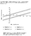
しかしながらマルチホップ通信システムの適用性を検証するために実行されたシミュレーションは、予想に反して低いデータスループットである結果を示した(図2A,2B)。実際、影響を受けるゲインはパスロスの数式Aに基づく簡易な分析で示唆されるポテンシャルゲインを大きく下回る。その結果、信号範囲の拡張性、ソース及び宛先間での信号伝送に要する全送信電力を潜在的に削減できること、及びマルチホップでなかったならば到達できなかったノードへの接続性等の観点においてマルチホップシステムが示す潜在的な利点にもかかわらず、従来無線システムオペレータはマルチホップネトワークを実現することを思いとどまっている。 However, simulations performed to verify the applicability of multi-hop communication systems have shown unexpectedly low data throughput (FIGS. 2A, 2B). In fact, the affected gain is much lower than the potential gain suggested by a simple analysis based on the path loss equation A. As a result, in terms of scalability of the signal range, the potential to reduce the total transmission power required for signal transmission between the source and destination, connectivity to nodes that could not be reached if not multi-hop, etc. Despite the potential benefits that multi-hop systems exhibit, traditional radio system operators have discouraged from implementing multi-hop networks.
特許文献1乃至6は本願の発明者等により以前に提案された技法に関連し、マルチホップ通信システムにおけるデータのスループットを改善しようとしている。これらの先行する出願内容の全ては本願のリファレンスに組み入れられる。
上述の先行する出願で説明されている発明は、マルチホップネットワークにおける1以上の通信リンク上での伝送リソース割当を決定及び制御するための様々な技法に関連し、その技法はi)宛先装置で受信した通信信号の品質の指標(measure)及びii)その又は各々の中間装置で受信された通信信号の品質の指標間の均衡を実質的に達成又は維持するようにする。つまり、これらの提案によれば、各リンクを介したデータスループットが実質的に等しくなるように又は近似的に等しくなるように、無線リソースの割当が維持及び制御される。特に、上記の各出願ではマルチホップシステムにおける無線リソース割り当ての管理及び制御を実行あらしめるために多数の様々なアルゴリズムが説明されている。特に以前に提案済みのアルゴリズムは、マルチホップネットワークの受信機で受信された通信信号品質に生じる「不均衡(imbalance)」を検出し、ネットワーク中の1以上の送信機に割り当てられるリソースの指標又は指標の変化を、所望の均衡が達成又は維持されるように決定しようとする。 The invention described in the above prior application relates to various techniques for determining and controlling transmission resource assignments on one or more communication links in a multi-hop network, the techniques being i) at the destination device. A balance between the received communication signal quality measure and ii) the balance between the received communication signal quality measure at or at each intermediate device is substantially achieved or maintained. That is, according to these proposals, the allocation of radio resources is maintained and controlled so that the data throughput over each link is substantially equal or approximately equal. In particular, in each of the above applications, a number of different algorithms are described for implementing management and control of radio resource allocation in a multi-hop system. In particular, the previously proposed algorithm detects an “imbalance” that occurs in the communication signal quality received at the receiver of the multi-hop network, and is an indicator of the resources allocated to one or more transmitters in the network, or An attempt is made to determine the change in the index so that the desired equilibrium is achieved or maintained.
本願発明者等により過去に提案されたリソース制御手法の効果を検証するためになされたシステムレベルのシミュレーション結果は、本明細書の末尾に用意されている。これらの結果は、「均衡している」マルチホップ通信システムはデータスループットの改善をもたらすことが期待できることを示す。これらのリソース管理手法により実証される改善されたスループットに関する理由の1つは、マルチホップシステムで必要とされる絶対的な送信電力を低減可能にするすることである。以下、このことを詳細に説明する。 System-level simulation results made in order to verify the effects of resource control techniques proposed in the past by the inventors of the present application are prepared at the end of this specification. These results show that a “balanced” multi-hop communication system can be expected to provide improved data throughput. One of the reasons for the improved throughput demonstrated by these resource management approaches is to enable the absolute transmit power required in multi-hop systems to be reduced. This will be described in detail below.
上述したように、単一の直接的な伝送リンクを2つのより短い伝送リンクに分割することで、或る信号が受ける全パスロス(トータルパスロス)を軽減することが達成されうる。つまり、ソース装置から宛先装置へ少なくとも1つの中間装置を介して通信信号を送信するのに要する送信電力全体は、ソース装置及び宛先装置間で直接的に通信信号を送信するのに要するものより少なくなる。かくて、宛先装置が(及びおそらくは中間装置も)最少の又は「ターゲットの(目標の)」信号品質で受けることを保証するのに、少ない送信電力しか必要としなくて済む。仮に、マルチホップシステムで送信機の送信電力に何の調整もなされなかったならば、かなりの過剰な送信電力(即ち、宛先装置及び/又は中間装置で良好な又は目標の信号品質を得るのに必要なものを超える送信電力)が生じる結果になるであろう。ソース装置及び宛先装置間での直接的な通信に比較して、マルチホップ通信で達成されるゲインを更に増やすように機能するのではなく、この過剰な送信電力は通信リンクの品質劣化を招く干渉レベルを単に増やしてしまう。この劣化は、従来想定されていたマルチホップ通信システムの貧弱なシミュレーション結果で実証されているように、マルチホップシステムの潜在的なゲインを減殺させる傾向がある。 As described above, dividing a single direct transmission link into two shorter transmission links can reduce the total path loss (total path loss) experienced by a signal. That is, the overall transmission power required to transmit a communication signal from the source device to the destination device via at least one intermediate device is less than that required to directly transmit the communication signal between the source device and the destination device. Become. Thus, less transmission power is required to ensure that the destination device (and possibly also the intermediate device) receives with minimal or “target” signal quality. If no adjustments were made to the transmitter's transmit power in a multi-hop system, a significant excess of transmit power (ie, to obtain good or target signal quality at the destination and / or intermediate device) Will result in transmission power exceeding what is needed). Rather than functioning to further increase the gain achieved in multi-hop communication compared to direct communication between the source and destination devices, this excess transmission power is an interference that leads to quality degradation of the communication link. Simply increase the level. This degradation tends to diminish the potential gain of the multi-hop system, as demonstrated by poor simulation results of previously assumed multi-hop communication systems.
更に(例えば)2ホップシステムにわたる全体的なスループットは:中間装置で受信されるデータパケット数及び宛先装置で受信されるデータパケット数の少ない方によって制限される。受信機で受信されるデータパケット数は、その受信機で終端する通信リンクの品質に依存する。これは例えば受信信号強度(RSS)の測定値又は信号対干渉プラス雑音比率(SINR)の指標に反映されかもしれない。かくて実際上マルチホップシステム中の最低品質の通信信号を受信する受信機が、データパケット伝送に関する「ボトルネック」を形成し、これによりマルチホップシステム内の他のリンクにおけるデータ伝送容量を浪費する。送信機に割り当てられるリソースを増やすことは、その最低品質の通信信号を改善するようには機能せず、余分なリソース割り当ての結果になる。従ってそのシステムパフォーマンスでは更なる劣化が生じる。これは図14A及び14Bに示されている。これらはソース装置(NB)の送信電力に対して、シングルホップシステムで観測されたものと比較した、2ホップシステムのユーザによって観測された平均パケットスループットのゲイン変化をプロットしている。各グラフは4つのプロットを含み、各々は中間装置の異なる送信電力に関連する。基地局の送信電力が最適点を超えて増やされると、より多くの信号エネルギの送出があるにも関わらず、ゲインの顕著な劣化が生じることが理解できる。 Furthermore, the overall throughput over (for example) a two-hop system is limited by: the number of data packets received at the intermediate device and the smaller number of data packets received at the destination device. The number of data packets received at a receiver depends on the quality of the communication link that terminates at that receiver. This may be reflected, for example, in a received signal strength (RSS) measurement or an indicator of signal to interference plus noise ratio (SINR). Thus, a receiver that actually receives the lowest quality communication signal in a multi-hop system creates a “bottleneck” for data packet transmission, thereby wasting data transmission capacity on other links in the multi-hop system. . Increasing the resources allocated to the transmitter does not work to improve its lowest quality communication signal and results in extra resource allocation. Therefore, further deterioration occurs in the system performance. This is illustrated in FIGS. 14A and 14B. These plot the gain change in average packet throughput observed by a user of a two-hop system compared to that observed in a single-hop system against the transmission power of the source device (NB). Each graph contains four plots, each associated with a different transmit power of the intermediate device. It can be seen that if the base station transmit power is increased beyond the optimum point, significant gain degradation occurs despite more signal energy being delivered.
リソース管理エンティティを用いるマルチホップ通信システムで実証される改善効果は、宛先装置で受信される通信信号品質の指標と1つ又は複数の中間装置各々で受信される通信信号品質の指標との間の何らかのバランスが実質的に欠ける又は妨げられる場合に貢献できると考えられる。かくて、データパケットのスループットを改善できず且つ干渉レベルを上昇させるようにしか機能しなかった過剰なリソース割り当ては最小化される。 The improvement demonstrated in multi-hop communication systems using resource management entities is between the communication signal quality indicator received at the destination device and the communication signal quality indicator received at each of the one or more intermediate devices. It is believed that it can contribute if some balance is substantially lacking or prevented. Thus, excessive resource allocation that could not improve the throughput of data packets and only functioned to increase the interference level is minimized.
上述の以前に提案済みの手法によれば、システムの送信機に割り当てられるリソース制御機能が、基地局に関連する部分で実現されることが有利であることが示されている。これは「セントラル化された制御(中央制御)と呼ばれ、無線ネットワークプロバイダには、リソース割り当て制御がシステムの中間装置に関連する部分で行われるよりも好まれる傾向がある。それ故に基地局に関連する単独のリソース制御手段が、送信機各々に割り当てられる送信リソースを制御するよう機能し、その送信機はマルチホップ通信経路に沿って宛先装置に向けて通信信号を送信するよう機能する。しかしながら、リソース制御手段を有するマルチホップ通信システムを実現することは、特にそれが基地局でセントラル化される場合、管理信号(制御信号)の形式でシステムを構成する他の通信装置からリソース制御手段に向かうシグナリングにおいて、一般にかなりの情報量を要求することになる。例えば通信信号を受信するマルチホップ通信システムを構成する装置は、受信している通信信号の品質のインジケータを導出するように機能する。これらのインジケータは、周期的に生成され、その通信経路に従ってその装置と基地局との間の通信経路上に位置する他の中間装置を経由して基地局のリソース制御手段へ通知される。以前に提案済みの技法によれば、リソース制御手段は、受信機で導出されるインジケータの所望値からの何らかの変化を検出する受信機又は手段各々により通知されるインジケータ間の何らかの実質的な不均衡を検出する手段と共に用意されてよい。そのような不均衡又は変化の検出に応答して、リソース制御手段は1以上の装置に割り当てられるリソースの指標又は指標の変化を確認するよう機能し、その1以上の装置は通信信号(又はその派生物)を送信しているものであり、受信機で導出されるインジケータ間の均衡を実質的に達成又は維持しようとする。何らかの新たな送信リソース割り当て又はリソース割り当て変更は、送信リソースコマンド(TRC: Transmission Resource Command)信号を含む制御信号の形式で適切な通信装置に指示される。 According to the previously proposed approach described above, it has been shown to be advantageous that the resource control function assigned to the transmitter of the system is implemented in the part related to the base station. This is referred to as “centralized control (central control), and wireless network providers tend to prefer resource allocation control to being performed in the part related to the intermediate device of the system. A single associated resource control means functions to control the transmission resources assigned to each transmitter, which transmitter functions to transmit communication signals toward the destination device along the multi-hop communication path. Realizing a multi-hop communication system with resource control means, especially when it is centralized at the base station, from other communication devices constituting the system in the form of management signals (control signals) to resource control means Inbound signaling generally requires a significant amount of information, eg receiving a communication signal The devices that make up the multi-hop communication system function to derive indicators of the quality of the received communication signal, which are generated periodically and between the device and the base station according to the communication path. To the resource control means of the base station via other intermediate devices located on the communication path between them, according to a previously proposed technique, the resource control means A receiver or means for detecting any change from the desired value may be provided with means for detecting any substantial imbalance between the indicators signaled by each, in response to detecting such an imbalance or change. The resource control means functions to confirm an index of resources allocated to the one or more devices or a change in the index, and the one or more devices receive a communication signal ( Is trying to substantially achieve or maintain the balance between the indicators derived at the receiver, any new transmission resource allocation or resource allocation change is An appropriate communication device is instructed in the form of a control signal including a (TRC: Transmission Resource Command) signal.
図3に示されるように、各中間装置が受信機で受信した通信信号品質のインジケータを生成及び送信することに加えて、(図示の例では、基地局に関連する)他の装置により制御手段に向けて伝送されたインジケータを伝搬することが必要である。かくて、制御シグナリングの占める帯域は、マルチホップ通信システムを形成する通信リンク数と共に及び近隣の基地局と共に増加する。以前に考察されたマルチホップ通信システムにおける通信装置の制御信号の負荷は、マルチホップネットワーク内の装置の位置、通信の向き(UL又はDL)及びリソース制御手段の位置に依存する。ダウンリンク(DL)通信でセントラル化されたリソース制御手段が使用される場合、制御手段で必要とされる制御信号のシグナリング方向は、通信方向と反対になる。ソース装置から基地局への1以上の中間装置を介するアップリンク(UL)伝送の場合、シグナリング方向は通信方向と同じになる。 As shown in FIG. 3, in addition to generating and transmitting an indicator of the communication signal quality received by each intermediate device at the receiver, the control means by other devices (in the illustrated example, associated with the base station) It is necessary to propagate the indicator transmitted towards Thus, the bandwidth occupied by control signaling increases with the number of communication links forming a multi-hop communication system and with neighboring base stations. The load of the control signal of the communication device in the multi-hop communication system considered before depends on the position of the device in the multi-hop network, the direction of communication (UL or DL), and the position of the resource control means. When resource control means centralized in downlink (DL) communication are used, the signaling direction of the control signal required by the control means is opposite to the communication direction. For uplink (UL) transmission via one or more intermediate devices from the source device to the base station, the signaling direction is the same as the communication direction.
これらの先行技術に関するシグナリングオーバーヘッドは、通信システムの他の部分に或る機能が展開される場合には或る低度軽減できるかもしれない。例えば、宛先装置がインジケータ導出手段に加えてインジケータ変化検出手段を備え、宛先装置で受信した通信信号品質のインジケータをシグナリングするのではなく、その宛先装置がインジケータをモニタし、システムで不均衡の生じることを示す何らかの品質変化を検出できるようにしてもよい。そのような変化が検出された場合に、その宛先装置で終端する通信リンクに割り当てられる送信電力の調整要求が、リソース制御手段に通知されてもよい。しかしながらそれでもこの要求はマルチホップネットワークを介してリソース制御手段に伝搬されなければならない。 These prior art signaling overheads may be reduced to some degree if certain functions are deployed in other parts of the communication system. For example, the destination device includes indicator change detection means in addition to the indicator derivation means, and instead of signaling an indicator of the communication signal quality received at the destination device, the destination device monitors the indicator, resulting in an imbalance in the system It may be possible to detect some quality change indicating that. When such a change is detected, a request for adjusting the transmission power allocated to the communication link terminating at the destination device may be notified to the resource control means. However, this request must still be propagated to the resource control means via the multihop network.
かくて本発明に関し、制御信号は例えば通信装置で受信された通信信号の品質の指標を表すかもしれないし、通信装置に割り当てられた送信リソースを反映する送信リソースコマンド(TRC)を表すかもしれないし、或いは特定の通信装置に割り当てられるリソースの変更又は新たなリソース割当の要求を示すかもしれない。 Thus, for the present invention, the control signal may represent, for example, an indicator of the quality of the communication signal received at the communication device, or may represent a transmission resource command (TRC) reflecting the transmission resource assigned to the communication device. Or a change of resources allocated to a specific communication device or a request for new resource allocation.
本発明の課題は、マルチホップ通信システムに関連するシグナリングオーバーヘッドを軽減することであり、そのオーバーヘッドは1より多くの通信リンクで伝送される1以上の制御信号に必要なものである。従って本発明の実施例は、マルチホップ通信システムにおける制御信号の伝送効率を改善しようとし、特にマルチホップ通信システムは、本願発明者等の先行する発明に関するリファレンスで説明されているような各通信リンクに割り当てられた送信リソースのバランスをとるためのリソース制御技術を利用するが、本発明はそれに限定されない。 An object of the present invention is to reduce signaling overhead associated with multi-hop communication systems, which is necessary for one or more control signals transmitted over more than one communication link. Accordingly, embodiments of the present invention seek to improve the transmission efficiency of control signals in a multi-hop communication system, and in particular, the multi-hop communication system is a communication link as described in the prior art reference of the present inventors. Although a resource control technique for balancing transmission resources allocated to the network is used, the present invention is not limited to this.
本発明の一形態によれば、少なくとも3つの通信装置を含むマルチホップ通信システムが使用され、前記通信装置の1つはソース装置を構成し、別の通信装置は宛先装置を構成し、他の通信装置各々は中間装置を構成し、前記ソース装置は通信信号を或る通信方向で各中間装置を介して前記宛先装置に向けて送信し、各中間装置は、該通信方向で前の通信装置から通信信号を受信し、前記通信信号を又は該通信信号から導出された信号を該通信方向で後の通信装置に送信し、当該マルチホップ通信システムは、前記ソース装置及び各中継装置の1以上に割り当てられる送信リソースの指標又は指標の変更を決定するリソース制御手段を更に有し、前記リソース制御手段は、i)前記宛先装置で受信された前記通信信号の品質の指標及びii)各中間装置で受信された前記通信信号の品質の指標の間のバランスをとることを実質的に達成する又は維持するように動作し、少なくとも1つの通信装置は、該通信方向で前の通信装置から1以上の制御信号を受ける制御信号処理手段を有し、該制御信号処理手段は、a)当該マルチホップ通信システムの通信装置により導出された絶対値を表す絶対的な制御信号及びb)前記絶対値に相対的な、当該マルチホップ通信システムの別の通信装置により導出された相対値を表す少なくとも1つの相対的な制御信号 を導出し、前記別の通信装置は、前記絶対的な制御信号及び前記少なくとも1つの相対的な制御信号を該通信方向で後の通信装置に送信することを特徴とするマルチホップ通信システムである。 According to one aspect of the invention, a multi-hop communication system including at least three communication devices is used, one of the communication devices constituting a source device, another communication device constituting a destination device, and the other Each communication device constitutes an intermediate device, the source device transmits a communication signal in a certain communication direction to each of the destination devices via each intermediate device, and each intermediate device is a previous communication device in the communication direction. A communication signal is received from the communication device, and the communication signal or a signal derived from the communication signal is transmitted to a subsequent communication device in the communication direction, and the multi-hop communication system includes at least one of the source device and each relay device. Further includes resource control means for determining an index of transmission resources allocated to or a change of the index, wherein the resource control means includes i) an index of the quality of the communication signal received by the destination device, and ii) each intermediate Operative to substantially achieve or maintain a balance between the quality indicators of the communication signals received at a location, wherein at least one communication device is one from the previous communication device in the communication direction. Control signal processing means for receiving the above control signal, the control signal processing means, a) an absolute control signal representing an absolute value derived by a communication device of the multi-hop communication system, and b) the absolute value To at least one relative control signal representing a relative value derived by another communication device of the multi-hop communication system, wherein the another communication device is configured to output the absolute control signal and the A multi-hop communication system, wherein at least one relative control signal is transmitted to a subsequent communication device in the communication direction.
「ある通信方向における前の(previous)通信装置」及び「ある通信方向における後の(subsequent)通信装置」なる用語は、意図される宛先装置へ通信装置により通信信号が伝送される順序を示すことに留意を要する。これは、通信信号が或る宛先としての基地局と共にアップリンクで送信されているか、或いはソース装置としての基地局及び宛先としてのユーザ装置と共にダウンリンクで送信されているか否かに依存する。同様に、「ある通信方向における前の通信装置」及び「ある通信方向における後の通信装置」は、制御信号がマルチホップ通信システムで伝送される順序に関連する。 The terms "previous communication device in a communication direction" and "subsequent communication device in a communication direction" indicate the order in which communication signals are transmitted by the communication device to the intended destination device. Please pay attention to. This depends on whether the communication signal is transmitted in the uplink with a base station as a destination, or in the downlink with a base station as a source device and a user device as a destination. Similarly, “the previous communication device in a certain communication direction” and “the subsequent communication device in a certain communication direction” relate to the order in which the control signals are transmitted in the multi-hop communication system.
ソース装置から送信される通信信号は、マルチホップ通信システムを構成するその又は各々の中間装置によって修正又は変更されてよいことが理解されるべきである。従って宛先装置で実際に受信された通信信号は、ソース装置によって送信された通信信号かもしれないし、或いはその通信信号から導出された通信信号もしれない。 It should be understood that the communication signal transmitted from the source device may be modified or changed by that or each intermediate device comprising the multi-hop communication system. Therefore, the communication signal actually received by the destination device may be a communication signal transmitted by the source device, or may not be a communication signal derived from the communication signal.
本発明の実施例は、送信リソース制御技法を実現するのに必要な制御シグナリングオーバーヘッドを減らす点で有利である。特に、関連する制御信号のビット数は、参照信号を形成する絶対制御信号に関する制御ビットよりかなり少なくなる。これはシステムがバランスをとっている場合又は非常に僅かな不均衡しか存在しない場合に特にその傾向が強い。なぜなら、マルチホップシステムで通信信号を受信している2つの通信装置で導出される値の間の相対的なオフセット(ズレ)は全く無い又はほとんど無いからである。実際、バランスのとれたシステムでは、UEがDLで受信した通信信号品質を報告するために単独の制御信号を基地局に送信するほとんどのシングルホップ通信システムの制御シグナリング負担に比べて追加される制御シグナリング負担が、ゼロになる又はゼロに近くなる。 Embodiments of the present invention are advantageous in that they reduce the control signaling overhead required to implement transmission resource control techniques. In particular, the number of bits of the associated control signal is considerably less than the control bits for the absolute control signal forming the reference signal. This is especially true when the system is balanced or when there is very little imbalance. This is because there is no or almost no relative offset (deviation) between values derived by two communication devices receiving communication signals in a multi-hop system. In fact, in a balanced system, the control added to the control signaling burden of most single-hop communication systems that send a single control signal to the base station to report the communication signal quality received by the UE in the DL. The signaling burden is zero or close to zero.
好ましくは、制御信号処理手段で導出された絶対制御信号(absolute administrative signal)は、絶対制御信号処理手段を有する通信装置で導出された絶対値を有する。或いは、制御信号処理手段で導出された絶対制御信号は、そのシグナリング方向で前の通信装置により導出された絶対値を有する。制御信号が特定のリンクで絶対制御信号になるようにする選択肢は、好ましくは、制御信号処理手段の信号処理要請を最小化する観点から、マルチホップシステムの配備設定を行わせる。例えば、基地局及び中継ノード(RN)の相対的な位置が固定されていた場合、基地局及びRN間を伝搬する通信信号の受けるパスロスは顕著には変化せず、このリンクで伝送される通信信号品質を表す絶対値を送信することが有意義になるかもしれないし、制御信号処理手段にとって、或るシグナリング方向で他の前の通信リンクで伝送される通信信号品質を反映するように相対的な制御信号を決定することが有意義になるかもしれない。 Preferably, the absolute control signal derived by the control signal processing means has an absolute value derived by the communication apparatus having the absolute control signal processing means. Alternatively, the absolute control signal derived by the control signal processing means has an absolute value derived by the previous communication device in the signaling direction. The option of causing the control signal to be an absolute control signal on a specific link preferably allows the multi-hop system to be deployed from the viewpoint of minimizing the signal processing requirements of the control signal processing means. For example, when the relative positions of the base station and the relay node (RN) are fixed, the path loss received by the communication signal propagating between the base station and the RN does not change significantly, and communication transmitted through this link It may be meaningful to send an absolute value that represents the signal quality and is relative to the control signal processing means to reflect the communication signal quality transmitted on other previous communication links in one signaling direction. It may be meaningful to determine the control signal.
ダウンリンク通信の場合、ソース装置は基地局の一部であり、基地局は通信信号をその又は各々の中間装置を経て宛先装置に送信する。アップリンク通信の場合、宛先装置は基地局の一部であり、基地局はその又は各々の中間装置を介してソース装置から送信された通信信号を受信するよう機能する。 For downlink communication, the source device is part of the base station, and the base station transmits the communication signal to the destination device via its or each intermediate device. For uplink communication, the destination device is part of the base station, and the base station functions to receive communication signals transmitted from the source device via its or each intermediate device.
本発明の或る形態によれば、リソース制御手段が基地局に備えられる。或いは、リソース制御手段は中間装置に設けられてもよい。この場合、本発明は、制御シグナリング情報が1より多くの中間装置を介して伝搬される必要のある場合にも適用可能になる。例えば、マルチホップネットワークは、基地局、アドバンスト(機能強化された)中継ノード、シンプルな(機能強化されてない)ノード及びユーザ装置を有してもよい。リソース制御手段が、アドバンスト中継ノードに備わり(選択的に、基地局でもよい)、シンプル中継ノードにより受信される制御信号は、絶対的制御信号及び相対的制御信号の形式でアドバンスト中継ノードに伝搬されてもよい。 According to an aspect of the present invention, resource control means is provided in the base station. Alternatively, the resource control means may be provided in the intermediate device. In this case, the present invention is also applicable when control signaling information needs to be propagated through more than one intermediate device. For example, a multi-hop network may have base stations, advanced (enhanced) relay nodes, simple (non-enhanced) nodes and user equipment. The resource control means is provided in the advanced relay node (optionally may be a base station), and the control signal received by the simple relay node is propagated to the advanced relay node in the form of an absolute control signal and a relative control signal. May be.
リソース制御手段を有するマルチホップ通信システムと共に使用される本発明の一形態は、マルチホップ通信システムの通信装置で受信される通信信号の品質に関連する値を示す制御信号を必要とする。本発明の一形態によれば、リソース制御手段は:
i)当該マルチホップ通信システムの通信装置で導出された絶対値を表す絶対的な制御信号及び
ii)当該マルチホップ通信システムの別の通信装置により導出された、前記絶対値に対する相対値を表す少なくとも1つの相対的な制御信号
を受信し、前記絶対的な及び前記相対的な制御信号を使用して、前記ソース装置及び各中間装置の1より多くに割り当てられる送信リソースの指標又は指標の変更を決定する。
One form of the present invention used with a multi-hop communication system having resource control means requires a control signal indicating a value related to the quality of the communication signal received by the communication device of the multi-hop communication system. According to one aspect of the invention, the resource control means is:
i) an absolute control signal representing an absolute value derived by the communication device of the multi-hop communication system; and
ii) receiving at least one relative control signal derived by another communication device of the multi-hop communication system and representing the relative value to the absolute value, and using the absolute and relative control signal Then, an index of transmission resources allocated to more than one of the source apparatus and each intermediate apparatus or a change of the index is determined.
通信信号を受信する受信機又は装置により導出される品質インジケータは、その受信機で受信された通信信号の強度指標(例えば、RSS)を含んでよい。代替的に又は付加的に、受信機で導出されたインジケータの1つは、その装置で受信された通信信号の信号対干渉プラス雑音比率(SINR)の指標を含んでもよいし、或いは受信装置に設定されたターゲット受信信号品質からの、所与の装置で受信された通信信号の品質の変分の指標を含んでもよい。ターゲットからの変分インジケータは、ターゲットRSSからの変分、ターゲットSINRからの変分、又はRSS及びSINRの組み合わせに基づくターゲットからの変分でもよい。 The quality indicator derived by the receiver or device that receives the communication signal may include a strength indicator (eg, RSS) of the communication signal received at the receiver. Alternatively or additionally, one of the indicators derived at the receiver may include an indication of the signal-to-interference plus noise ratio (SINR) of the communication signal received at the device, or to the receiving device An indication of a variation of the quality of the communication signal received at a given device from the set target received signal quality may be included. The variation indicator from the target may be a variation from the target RSS, a variation from the target SINR, or a variation from the target based on a combination of RSS and SINR.
上記の形態又は以下のどの形態でも、中間装置は好ましくはソース装置により送信された信号を受信する受信機;及び受信した信号又はそれから導出された信号を宛先装置に送信する送信機を有する。中間装置で受信される通信信号を中間装置で送信される通信信号から分離するための信号の二重化は、周波数分割二重化(FDD)でも時分割二重化(TDD)でもよい。1以上の中間装置は好ましくはいわゆる中継ノード(RN: relay node)又は中継局(RS: relay−station)から構成されてよい。意図される最終的宛先装置でない中継ノードは信号を受信し、その信号を別のノードに送信し、信号が意図される宛先に向かって進行するようにできる。中継ノードは、受信信号がビットレベルにデコードされてハード判定を行う再生タイプ(regenerate type)でもよい。受信したパケットに誤りが発見された場合には、再送が要求され、従ってRNはARQ又はH−ARQの機能を組み込んでいる。ARQ又はH−ARQは再送要求及び以後の再送信号の受信を管理する受信技法である。一旦パケットが良好に受信されると、RNに組み込まれた何らかの無線リソース管理法に基づいて、宛先装置に向けて再送が計画される(スケジューリングされる)。或いは中継ノードは非再生タイプでもよく、その場合データは中継ノードで増幅され、その信号が次の局に転送される。中間装置又は中継ノードの機能は移動電話機や他のユーザ装置に備わってよいことも想定されている。 In the above or any of the following forms, the intermediate device preferably comprises a receiver that receives the signal transmitted by the source device; and a transmitter that transmits the received signal or a signal derived therefrom to the destination device. The signal duplexing for separating the communication signal received by the intermediate device from the communication signal transmitted by the intermediate device may be frequency division duplex (FDD) or time division duplex (TDD). The one or more intermediate devices may preferably comprise so-called relay nodes (RNs) or relay stations (RSs). A relay node that is not the intended final destination device can receive the signal and send the signal to another node so that the signal travels towards the intended destination. The relay node may be a regenerate type in which a received signal is decoded to a bit level and a hard decision is made. If an error is found in the received packet, a retransmission is requested, so the RN incorporates ARQ or H-ARQ functionality. ARQ or H-ARQ is a reception technique for managing retransmission requests and subsequent reception of retransmission signals. Once the packet is successfully received, retransmissions are scheduled (scheduled) towards the destination device based on some radio resource management method built into the RN. Alternatively, the relay node may be a non-regenerative type, in which case the data is amplified at the relay node and the signal is transferred to the next station. It is also envisaged that the function of the intermediate device or relay node may be provided in a mobile telephone or other user device.
本発明の第2形態によれば、ソース装置として機能する通信装置から、宛先装置として機能する別の通信装置へ、中間装置として機能する少なくとも1つの他の通信装置を介して或る通信方向で通信信号を送信する方法が使用され、各中間装置は、該通信方向で前の通信装置から通信信号を受信し、前記通信信号を又は該通信信号から導出された信号を該通信方向で後の通信装置に送信し、
当該方法は、前記ソース装置及び各中継装置の1以上に割り当てられる送信リソースの指標又は指標の変更を決定するステップを有し、該ステップは、
i)前記宛先装置で受信された前記通信信号の品質の指標及び
ii)各中間装置で受信された前記通信信号の品質の指標
の間のバランスをとることを実質的に達成する又は維持するようにし、
少なくとも1つの通信装置は、該通信方向で前の通信装置から1以上の制御信号を受信し且つ
a)当該マルチホップ通信システムの通信装置により導出された絶対値を表す絶対的な制御信号及び
b)前記絶対値に相対的な、当該マルチホップ通信システムの別の通信装置により導出された相対値を表す少なくとも1つの相対的な制御信号
を導出し、前記絶対的な制御信号及び前記少なくとも1つの相対的な制御信号は、該通信方向で後の通信装置に送信されることを特徴とする。
According to the second aspect of the present invention, from a communication device functioning as a source device to another communication device functioning as a destination device, in a certain communication direction via at least one other communication device functioning as an intermediate device. A method of transmitting a communication signal is used, wherein each intermediate device receives a communication signal from a previous communication device in the communication direction, and transmits the communication signal or a signal derived from the communication signal in the communication direction. To the communication device,
The method comprises the step of determining an indicator of transmission resources allocated to one or more of the source device and each relay device or a change of an indicator, the step comprising:
i) an indicator of the quality of the communication signal received at the destination device;
ii) substantially achieve or maintain a balance between the quality indicators of the communication signals received at each intermediate device;
At least one communication device receives one or more control signals from a previous communication device in the communication direction; and
a) an absolute control signal representing an absolute value derived by the communication device of the multi-hop communication system, and
b) deriving at least one relative control signal representing a relative value derived by another communication device of the multi-hop communication system relative to the absolute value, the absolute control signal and the at least one Two relative control signals are transmitted in the communication direction to subsequent communication devices.
本発明の第3形態によれば、マルチホップ通信システムで使用する通信装置が使用され、該通信装置は送信機及び受信機を有し、ある通信方向で前の通信装置から通信信号を受信し、前記通信信号を又は該通信信号から導出された信号を該通信方向で後の通信装置に送信し、当該通信装置は、ある通信方向で前の通信装置から1以上の制御信号を受信する制御信号処理手段を有し、該制御信号処理手段は、
a)前記マルチホップ通信システムの通信装置により導出された絶対値を表す絶対的な制御信号及び
b)前記絶対値に相対的な、前記マルチホップ通信システムの別の通信装置により導出された相対値を表す少なくとも1つの相対的な制御信号
を導出し、当該通信装置は、前記絶対的な制御信号及び各相対的な制御信号を該通信方向で後の通信装置に送信する
ことを特徴とする。
According to the third aspect of the present invention, a communication device used in a multi-hop communication system is used, the communication device has a transmitter and a receiver, and receives a communication signal from a previous communication device in a certain communication direction. The communication signal or a signal derived from the communication signal is transmitted to a subsequent communication device in the communication direction, and the communication device receives one or more control signals from the previous communication device in a communication direction. Signal processing means, the control signal processing means,
a) an absolute control signal representing an absolute value derived by the communication device of the multi-hop communication system;
b) deriving at least one relative control signal representing a relative value derived by another communication device of the multi-hop communication system relative to the absolute value, wherein the communication device The signal and each relative control signal are transmitted to a subsequent communication device in the communication direction.
好ましくは通信装置はインジケータ導出手段を更に有し、インジケータ導出手段は通信装置で受信した通信信号品質のインジケータを導出する。 Preferably, the communication device further includes an indicator deriving unit, and the indicator deriving unit derives an indicator of communication signal quality received by the communication device.
第3形態の通信装置はマルチホップ通信システムの中間装置を構成してもよく、ある通信方向でソース装置として機能する通信装置から宛先装置として機能する別の通信装置に向けて前記中間装置を介して通信信号が送信され、当該通信装置は、
前記ソース装置及び各中継装置の1以上に割り当てられる送信リソースの指標又は指標の変更を決定するリソース制御手段を更に有し、前記リソース制御手段は、
i)前記宛先装置で受信された前記通信信号の品質の指標及び
ii)前記中間装置で受信された前記通信信号の品質の指標
の間のバランスをとることを実質的に達成する又は維持するように動作する。
The communication device of the third form may constitute an intermediate device of a multi-hop communication system, and the communication device that functions as a source device in a certain communication direction passes through the intermediate device toward another communication device that functions as a destination device. Communication signal is transmitted, and the communication device
Resource control means for determining an index of transmission resources allocated to one or more of the source device and each relay apparatus or a change of the index, the resource control means,
i) an indicator of the quality of the communication signal received at the destination device;
ii) operate to substantially achieve or maintain a balance between the quality indicators of the communication signals received at the intermediate device;
本発明の第4形態によれば、マルチホップ通信システムで使用する基地局が使用され、ある通信方向で宛先装置として機能する通信装置に中間装置として機能する別の通信装置を介して通信信号を送信し、当該基地局は、前記ソース装置及び各中継装置の1以上に割り当てられる送信リソースの指標又は指標の変更を決定するリソース制御手段を有し、前記リソース制御手段は、
i)前記宛先装置で受信された前記通信信号の品質の指標及び
ii)各中間装置で受信された前記通信信号の品質の指標
の間のバランスをとることを実質的に達成する又は維持するように動作し、
当該基地局は、
a)当該マルチホップ通信システムの通信装置により導出された絶対値を表す絶対的な制御信号及び
b)前記絶対値に相対的な、前記マルチホップ通信システムの別の通信装置により導出された相対値を表す少なくとも1つの相対的な制御信号
を受信し、前記絶対的な及び前記相対的な制御信号を用いて、前記ソース装置及び各中間装置の1以上に割り当てられる送信リソースの指標又は指標の変更を決定する。
According to the fourth aspect of the present invention, a base station used in a multi-hop communication system is used, and a communication signal is transmitted to a communication apparatus that functions as a destination apparatus in a certain communication direction via another communication apparatus that functions as an intermediate apparatus. Transmitting, the base station has resource control means for determining an index of transmission resources allocated to one or more of the source apparatus and each relay apparatus or a change of the index, and the resource control means includes:
i) an indicator of the quality of the communication signal received at the destination device;
ii) operate to substantially achieve or maintain a balance between the quality indicators of the communication signals received at each intermediate device;
The base station
a) an absolute control signal representing an absolute value derived by the communication device of the multi-hop communication system, and
b) receiving at least one relative control signal representative of a relative value derived by another communication device of the multi-hop communication system relative to the absolute value and receiving the absolute and relative control A signal is used to determine an indicator of transmission resources assigned to one or more of the source device and each intermediate device, or a change in the indicator.
本発明の第5形態によれば、マルチホップ通信システムで使用する基地局が使用され、ある通信方向で宛先装置として機能する通信装置から送信された通信信号を中間装置として機能する別の通信装置を介して受信し、当該基地局は、前記ソース装置及び各中継装置の1以上に割り当てられる送信リソースの指標又は指標の変更を決定するリソース制御手段を有し、前記リソース制御手段は、
i)前記宛先装置で受信された前記通信信号の品質の指標及び
ii)各中間装置で受信された前記通信信号の品質の指標
の間のバランスをとることを実質的に達成する又は維持するように動作し、
当該基地局は、
a)当該マルチホップ通信システムの通信装置により導出された絶対値を表す絶対的な制御信号及び
b)前記絶対値に相対的な、前記マルチホップ通信システムの別の通信装置により導出された相対値を表す少なくとも1つの相対的な制御信号
を受信し、前記絶対的な及び前記相対的な制御信号を用いて、前記ソース装置及び各中間装置の1以上に割り当てられる送信リソースの指標又は指標の変更を決定する。
According to the fifth aspect of the present invention, another base station used in a multi-hop communication system is used, and another communication apparatus that functions as an intermediate apparatus for a communication signal transmitted from a communication apparatus that functions as a destination apparatus in a certain communication direction. The base station has resource control means for determining an index of transmission resources allocated to one or more of the source apparatus and each relay apparatus or a change in the index, and the resource control means includes:
i) an indicator of the quality of the communication signal received at the destination device;
ii) operate to substantially achieve or maintain a balance between the quality indicators of the communication signals received at each intermediate device;
The base station
a) an absolute control signal representing an absolute value derived by the communication device of the multi-hop communication system, and
b) receiving at least one relative control signal representative of a relative value derived by another communication device of the multi-hop communication system relative to the absolute value and receiving the absolute and relative control A signal is used to determine an indicator of transmission resources assigned to one or more of the source device and each intermediate device, or a change in the indicator.
本発明は以前のマルチホップ通信システム(リソース制御手段を利用するシステム)のシグナリング効率を改善する観点から発展してきたが、本発明は、1より多くのリンクで伝送される制御信号を必要とする如何なるマルチホップシステムにもより一般的に適用可能であることも想定されており、それらの制御信号は相対的な値で表現されてもよい。 Although the present invention has been developed from the viewpoint of improving the signaling efficiency of previous multi-hop communication systems (systems using resource control means), the present invention requires control signals transmitted on more than one link. It is also assumed that the present invention is more generally applicable to any multi-hop system, and those control signals may be expressed as relative values.
従って本発明の更なる形態によれば、少なくとも3つの通信装置で構成されるマルチホップ通信システムが提供され、通信装置の1つはソース装置を構成し、別の通信装置は宛先装置を構成し、別の通信装置は中間装置を構成し、ソース装置は通信信号を或る通信方向で宛先装置に向けてその又は各々の中間装置を介して送信し、その又は各々の中間装置は通信信号をその通信方向で前の通信装置から受信し、その通信信号を又はそれから導出された信号をその通信方向で後の装置に送信し、少なくとも1つの通信装置は制御信号処理手段を有し、制御信号処理手段は、1以上の制御信号をそのシグナリング方向で前の通信装置から受信し、a)マルチホップシステムの通信装置で導出された絶対値を表す絶対的制御信号を;及びb)マルチホップシステムの別の通信装置により導出された、絶対値に対する相対値を示す少なくとも1つの相対的制御信号を導出し、当該通信装置は絶対的制御信号及び少なくとも1つの相対的制御信号をそのシグナリング方向で後の通信装置に送信するよう更に機能する。 Thus, according to a further aspect of the present invention, there is provided a multi-hop communication system comprising at least three communication devices, one of the communication devices constituting a source device and another communication device constituting a destination device. The other communication device constitutes an intermediate device, the source device transmits a communication signal in a certain communication direction to the destination device via the or each intermediate device, and the or each intermediate device transmits the communication signal. Receiving from the previous communication device in the communication direction and transmitting the communication signal or a signal derived therefrom to the subsequent device in the communication direction, the at least one communication device having control signal processing means, The processing means receives one or more control signals from the previous communication device in its signaling direction, a) an absolute control signal representing an absolute value derived at the communication device of the multihop system; and b) multi Deriving at least one relative control signal, which is derived by another communication device of the network system and indicating a relative value to the absolute value, the communication device outputs the absolute control signal and at least one relative control signal in its signaling direction. It further functions to transmit to a later communication device.
使用される本発明の形態は、マルチホップシステムの配備に先立って、システムを最適化すること、及び/又は各中間装置で受信される通信信号品質の指標と宛先装置で受信される通信信号品質の指標との実質的なバランスをとることも想定されている。本発明の一形態は、全てのリンクにおける通信信号品質の指標の「バランス」をとるために及び維持するために、マルチホップシステム内で実現されてよいことも想定されている。かくて本発明はマルチホップ通信システム内で使用され、宛先装置でのRSS又はSINRのインジケータと、各中間装置でのRSS又はSINRのインジケータとの間の実質的な「バランス」をとるようにしてもよい。送信電力は有利なことにマルチホップシステムで通信信号を受信する装置の1つについてターゲット受信信号皮質に関して当初に最適化されてもよい。これは通常的には宛先装置である。かくてターゲット受信信号品質からの、宛先装置で受信された通信信号品質の変化の指標のインジケータ(=「ターゲットからの変化」インジケータ)は、有利なことに、システムが本発明の一形態により最適化される場合に最小化される。以後、正に又は負にターゲットインジケータからのズレの変化が検出されると、例えば通信信号品質が劣化した又は改善された場合に、又は装置のターゲット設定が変わった場合、ターゲットインジケータからの変分が増える。この場合、所望値からのターゲットインジケータからのズレの変位を検出可能にする本発明の一形態は、有利なことに、ターゲットインジケータからの変分を所望の値にもってゆくようにする。 The form of the invention used is to optimize the system prior to the deployment of the multi-hop system and / or the communication signal quality indicator received at each intermediate device and the communication signal quality received at the destination device. A substantial balance with other indicators is also assumed. It is also envisioned that an aspect of the present invention may be implemented in a multi-hop system to “balance” and maintain communication signal quality metrics across all links. Thus, the present invention is used in a multi-hop communication system to provide a substantial “balance” between the RSS or SINR indicator at the destination device and the RSS or SINR indicator at each intermediate device. Also good. The transmit power may advantageously be initially optimized with respect to the target received signal cortex for one of the devices receiving the communication signal in a multi-hop system. This is usually the destination device. Thus, an indicator of the change in the quality of the communication signal received at the destination device from the target received signal quality (= “change from target” indicator) is advantageously optimized by the system according to one aspect of the present invention. Is minimized if Thereafter, when a change in the deviation from the target indicator is detected positively or negatively, for example, when the communication signal quality is deteriorated or improved, or when the target setting of the apparatus is changed, the deviation from the target indicator is changed. Will increase. In this case, one form of the present invention that allows detection of the deviation of the deviation from the target indicator from the desired value advantageously allows the variation from the target indicator to be brought to the desired value.
送信機での送信電力、送信帯域、アンテナ数、符号化率、変調方式等の割当を含む多数の様々なリソースタイプが存在する。ある帯域幅の割当が使用される場合、それは全ての伝送媒体の内の一部として効果的に決定され、実際に割り当てられるリソースは使用されるチャネルアクセス法に依存する。例えば時分割多重接続(TDMA)システムでは、受信機と通信するために、送信機の送信に許可されるタイムスロット数又は時間長になる。時間長が長ければ長いほど又は使用されるスロット数が多ければ多いほど、特定の通信リンクに割り当てられる帯域は多くなる。同様に(直交)周波数分割多重接続(OFDMA/FDMA)システムの場合には、割り当ては周波数帯域キャリア又はキャリア数の割り当てになる。更に各キャリアに関連する周波数量は変更されてもよい。最後にCDMAシステムの場合には、ソース及び宛先間の通信に利用されるコード数−即ち何らかのコードに使用される拡散率−になる。どのリソース割当法も、送信電力の場合と同様な手法で、ソースから宛先へ伝送可能なデータレートを効果的に制御する。 There are a number of different resource types including assignment of transmit power, transmit bandwidth, number of antennas, coding rate, modulation scheme, etc. at the transmitter. If a bandwidth allocation is used, it is effectively determined as part of all transmission media, and the actual allocated resources depend on the channel access method used. For example, in a time division multiple access (TDMA) system, in order to communicate with a receiver, the number of time slots or time length allowed for transmission by the transmitter is obtained. The longer the time length or the more slots used, the more bandwidth is allocated to a particular communication link. Similarly, in the case of (orthogonal) frequency division multiple access (OFDMA / FDMA) systems, the allocation is an allocation of frequency band carriers or number of carriers. Further, the amount of frequency associated with each carrier may be changed. Finally, in the case of a CDMA system, this is the number of codes used for communication between the source and the destination-that is, the spreading factor used for some code. Each resource allocation method effectively controls the data rate that can be transmitted from the source to the destination in the same manner as in the case of transmission power.
以下、本発明の様々な実施例が説明され、それらは、マルチホップ通信システムで通信信号を受信する装置によって導出される品質インジケータ間で実質的なバランスを維持するために、送信電力を割り当てる。 In the following, various embodiments of the present invention will be described, which allocate transmit power to maintain a substantial balance between quality indicators derived by an apparatus receiving communication signals in a multi-hop communication system.
上記のどの形態でも、様々な特徴はハードウエアで、1以上のプロセッサで動作するソフトウエアモジュールとして又はそれら2者の組み合わせとして実現されてもよい。例えば、上述したような通信装置はディジタル信号プロセッサ(DSP)のようなプロセッサ、又は或るプログラムに従って動作するコンピュータを備えてもよい。本発明はここに説明される何らかの方法を実行するコンピュータプログラム及びコンピュータプログラムプロダクトをも提供し、及びここに説明される何らかの方法を実行するプログラムを格納するコンピュータ読み取り可能な媒体をも提供する。本発明を利用するコンピュータプログラムはコンピュータ読み取り可能な媒体に格納されてもよいし、或いは例えばインターネットウェブサイトから提供されるダウンロード可能なデータ信号のような信号形式であってもよいし、又は他の如何なる形態でもよい。 In any of the above forms, the various features may be implemented in hardware, as software modules that run on one or more processors, or as a combination of the two. For example, a communication device as described above may comprise a processor such as a digital signal processor (DSP) or a computer that operates according to a program. The present invention also provides computer programs and computer program products that perform any of the methods described herein, and also provides computer readable media that store programs that perform any of the methods described herein. The computer program utilizing the present invention may be stored on a computer readable medium, or may be in a signal format such as a downloadable data signal provided by an internet website, or other Any form is acceptable.
本発明を更に理解し、本発明がどのように実行されるかを示すために、添付図面を参照する説明が以下に例示的になされる。 In order to better understand the present invention and to show how it may be implemented, a description with reference to the accompanying drawings is given below by way of example.
図4を参照するに、本発明の一実施例による2ホップ通信システムが示され、ダウンリンク(DL)通信信号CDLは、ノードB(NB)から中継ノード(RN)への第1リンクで及びその中継ノードからユーザ装置(UE)に至る第2リンクで伝送される。この例ではノードBがソース装置を構成し、中継ノードは中間装置を構成し、それは再生型の中継ノードでも非再生型の中継ノードでもよく、ユーザ装置は宛先装置を構成する。 Referring to FIG. 4, a two-hop communication system according to an embodiment of the present invention is shown. A downlink (DL) communication signal CDL is transmitted on a first link from a node B (NB) to a relay node (RN). And the second link from the relay node to the user equipment (UE). In this example, the node B constitutes a source device, the relay node constitutes an intermediate device, which may be a regenerative relay node or a non-regenerative relay node, and the user device constitutes a destination device.
マルチホップシステムで「不均衡」を招くおそれのある多数の様々なイベントが存在することを認識することは有用であろう(不均衡は、宛先装置で受信される通信信号の品質の指標と、中間装置で受信される通信信号の品質の指標との間の差である。):
i) あるリンクで生じるパスロスは変化する。これは、そのリンクに関する送信機及び受信機の双方又は一方の位置変化に起因するかもしれないし、又は送信機及び受信機間で生じる干渉レベル又は環境状態の変化に起因するかもしれない。
It would be useful to recognize that there are a large number of different events that can lead to an “imbalance” in a multi-hop system (an imbalance is an indication of the quality of the communication signal received at the destination device, and It is the difference between the quality of the communication signal received at the intermediate device.):
i) Path loss that occurs on a link changes. This may be due to a change in the location of the transmitter and / or receiver for that link, or may be due to a change in interference levels or environmental conditions that occur between the transmitter and the receiver.
ii) 通信信号を受信する装置について、ターゲットRSS又はターゲットSINRを用意することが通常的である。これは通常的にはネットワークプロバイダによって設定され、通信システムや受信装置の特性に依存して又は伝送されるデータタイプに依存して変化するかもしれない。移動電話又は他のユーザ装置のターゲットRSS/SINRが変わるかもしれないし、宛先装置で受信される通信信号品質のターゲット受信信号品質からの変分(即ち、「ターゲットからの変化」)の指標を最小化するように、送信装置に割り当てられた送信リソースを調整することで、如何なるターゲットの変化にも適応可能である。マルチホップシステムの場合、1つの受信装置におけるターゲット変化に適応するように、1つの装置に割り当てられる送信リソースを単に調整するだけでは、そのシステム内で不均衡を招いてしまう。 ii) It is usual to prepare a target RSS or target SINR for a device that receives a communication signal. This is usually set by the network provider and may vary depending on the characteristics of the communication system, the receiving device or the type of data being transmitted. The target RSS / SINR of the mobile phone or other user equipment may change, and the indication of the variation of the communication signal quality received at the destination equipment from the target received signal quality (ie, “change from target”) is minimized Therefore, it is possible to adapt to any target change by adjusting the transmission resource allocated to the transmission apparatus. In the case of a multi-hop system, simply adjusting transmission resources allocated to one device so as to adapt to target changes in one receiving device will cause imbalance in the system.
本実施例によれば、リソース制御手段(10)が基地局に用意され、NB及びRNの双方又は一方に割り当てられた送信リソースの指標又は指標の変化を判定するよう機能し、RNで受信される通信信号品質及びUEで受信される通信信号品質間の均衡を達成又は維持しようとする。この例では、使用される送信リソースは送信電力を含む。ユーザ装置及び中継ノードは継続的に受信信号強度をモニタし、受信信号強度の品質を表す値(例えば、ターゲットRSS/SINRからのRSS/SINRの変化)を導出する。これらのインジケータはリソース制御手段に制御信号(管理信号)として通知され、リソース制御に必要とされ、伝送リンク双方に割り当てられる送信リソースが管理され、RN及びUEでの受信信号強度の品質如何なる不均衡も或いは不均衡の可能性も最小化可能に又は抑制可能になるようにする。 According to the present embodiment, the resource control means (10) is prepared in the base station, functions to determine a transmission resource index or a change in the index allocated to one or both of the NB and the RN, and is received by the RN. Trying to achieve or maintain a balance between the communication signal quality to be received and the communication signal quality received at the UE. In this example, the transmission resource used includes transmission power. The user apparatus and the relay node continuously monitor the received signal strength and derive a value (for example, a change in RSS / SINR from the target RSS / SINR) indicating the quality of the received signal strength. These indicators are notified to the resource control means as control signals (management signals), required for resource control, transmission resources allocated to both transmission links are managed, received signal strength quality at RN and UE, any imbalance Alternatively, the possibility of imbalance can be minimized or suppressed.
上述の可能性のある何れかのイベントの発生の結果として生じる不均衡又は不均衡の可能性にリソース制御手段が応答できるように、本実施例では2つの別個のアルゴリズムが使用される。NBには、本実施例の第1アルゴリズムで必要なインジケータ変位検出手段(3)、及び本実施例の第2アルゴリズムで必要な不均衡検出手段(4)が備わっている。不均衡検出手段(4)は例えばパスロス更新手段を含んでよく、その手段は、宛先装置及び中間装置双方から導出されたインジケータに関連する制御信号の受信後に、又はインジケータの双方又は一方の変化の後に、NB及びRN間で及びRN及びUE間で伝送される通信信号の受けたパスロスの指標を判定する。 In this embodiment, two separate algorithms are used so that the resource control means can respond to the imbalance or potential imbalance resulting from the occurrence of any of the above mentioned possible events. The NB includes an indicator displacement detection means (3) necessary for the first algorithm of the present embodiment and an imbalance detection means (4) necessary for the second algorithm of the present embodiment. The imbalance detection means (4) may include, for example, a path loss update means, which means after receiving a control signal associated with an indicator derived from both the destination device and the intermediate device, or of a change in one or both of the indicators. Later, the index of the path loss received by the communication signal transmitted between the NB and the RN and between the RN and the UE is determined.
図5は本発明を使用する通信装置(11)の一部を示し、例えば図4に示される例の中間装置として使用されてもよい。本装置は、通信信号及び制御信号を送信する送信機(Tx)と、通信信号及び制御信号を受信する受信機(Rx)と、インジケータ変位手段(7)と、制御信号処理手段(6)とを有する。使用に際して制御信号処理手段は、インジケータ変位手段により導出されたインジケータを表す絶対的な制御信号と、インジケータ変位手段により導出されたインジケータに対して、別の通信装置により導出された値を表す1以上の相対的な制御信号とを生成する。
FIG. 5 shows a part of the
図6に示されるような第1アルゴリズムは、以下の手段を備える実施例の通信システムで使用される:
i)中間装置の新たな送信電力を計算することで、中間装置及び宛先装置間のパスロスの変化に起因して生じる不均衡に応答する手段;及び/又は
ii)中間装置及びソース装置の新たな送信電力を計算することで、宛先装置のターゲットの変化に続いて生じる可能性のある不均衡に応答する手段。
The first algorithm as shown in FIG. 6 is used in an example communication system comprising the following means:
i) means for responding to an imbalance caused by a change in path loss between the intermediate device and the destination device by calculating a new transmission power of the intermediate device; and / or
ii) A means for responding to imbalances that may occur following a change in the target of the destination device by calculating new transmit powers for the intermediate device and the source device.
図7に示されるような第2アルゴリズムは、以下の手段を備える実施例の通信システムで使用される:
宛先装置で受信した通信信号品質及び中間装置で受信した通信信号品質間の均衡を達成又は維持するようにソース装置の送信電力を調整する手段。特に、第2アルゴリズムではソース及び中間装置間のパスロス変化に起因して生じる不均衡に応答する手段を備えていることが有利である。
The second algorithm as shown in FIG. 7 is used in an example communication system comprising the following means:
Means for adjusting the transmission power of the source device to achieve or maintain a balance between the communication signal quality received at the destination device and the communication signal quality received at the intermediate device; In particular, it is advantageous for the second algorithm to include means for responding to imbalances caused by path loss changes between the source and intermediate devices.
新たなRN送信電力を計算可能にするために、NBの制御手段は現在のRN送信電力の情報を必要とする。この情報を得るために2つの技法が利用可能である:1)NBがRNの初期送信電力に加えて最大値の情報を有し;この情報は固有のものであってもよいし、RNがNBに接続するときに通知されてもよい。そしてNBは変更するコマンドが発行されるとRN送信電力を追跡する、或いは2)RNは現在の送信電力をNBに報告し、NBで追跡する必要をなくす。このアルゴリズムは、シグナリングの複雑さを減らす観点から、第1の技法が使用されることを想定している。 In order to be able to calculate a new RN transmission power, the control means of the NB needs information on the current RN transmission power. Two techniques are available to obtain this information: 1) NB has maximum information in addition to RN's initial transmit power; this information may be unique, You may be notified when connecting to NB. And NB tracks RN transmission power when a command to change is issued, or 2) RN reports the current transmission power to NB, eliminating the need for NB to track. This algorithm assumes that the first technique is used in terms of reducing signaling complexity.
第1アルゴリズムは以下のシーケンスを含む。 The first algorithm includes the following sequence.
1.宛先装置は絶対的な制御信号AUEをノードBのリソース制御手段に向けて中継ノードを介して送信する。絶対的な制御信号は、UEの受信機で受信された通信信号の品質の値を表す。 1. The destination device transmits an absolute control signal A UE to the resource control means of the node B via the relay node. The absolute control signal represents the quality value of the communication signal received by the UE receiver.
2.RNは制御信号をリソース制御手段に送信し、その制御信号はUEの受信機で受信された通信信号の品質を表す。RNにより送信され且つUEで受信される信号の品質に関連する制御信号は、UEにより導出される絶対的な制御信号AUEでもよいし、UEで導出された、制御信号ARNに対する相対値を表す相対的な制御信号AUE/RNでもよく、ARNはRNの受信機で受信された通信信号の品質の値を表す。 2. The RN transmits a control signal to the resource control means, and the control signal represents the quality of the communication signal received by the UE receiver. The control signal related to the quality of the signal transmitted by the RN and received by the UE may be an absolute control signal A UE derived by the UE, or a relative value for the control signal A RN derived by the UE. the relative administrative signal a UE / RN even better indicating, a RN represents the value of the quality of a communication signal received at the receiver of the RN.
3.NBに用意されたインジケータ変位検出手段(3)が、UEの受信機で受信された通信信号品質のインジケータの逸脱を検出すると、RNに割り当てられた送信リソースの変更要求がリソース制御手段(10)にローカルに通知され、逸脱はRN及びUE間のパスロスの変化を又はUEに設定されたターゲット受信信号品質の変化を反映する。 3. When the indicator displacement detection means (3) prepared in the NB detects a deviation of the indicator of the communication signal quality received by the receiver of the UE, a request for changing the transmission resource assigned to the RN is sent to the resource control means (10). And the deviation reflects a change in path loss between the RN and the UE or a change in target received signal quality set for the UE.
4.現在のRN送信電力の情報に基づいて、リソース制御手段は、そのRNについてリソース割当に必要な変更を満たすのに必要な新たなRNリソース割当を計算する。マルチホップシステムを制御するのに使用されるリソースのタイプが送信電力である場合、NBはRN送信電力の有限性を考慮に入れて、適切に新たな送信電力を調整する。 4). Based on the current RN transmission power information, the resource control means calculates a new RN resource allocation necessary for satisfying the change necessary for the resource allocation for the RN. If the type of resource used to control the multi-hop system is transmission power, the NB takes into account the finiteness of RN transmission power and adjusts the new transmission power appropriately.
5.そして:
i)(本実施例の第2アルゴリズムで導出される入力信号により決定されるように)RN-UE伝搬損失の変化が一切生じなかったことが検出されたならば、RN-UE伝搬損失の変化ではなく、UEでのターゲット変化に起因して、要求が生成される。この場合に、リソース制御手段もNBについて新たなリソース割当を算出する。NBリソース割当を充足可能であることをNBは確認する(例えば、送信電力を増やす場合、最大送信電力は超えられない。)。最大値を超える場合、その電力変更はそのような超過が生じないように調整される。そしてRN送信電力は、均衡が達成されるように再計算される。そしてNBは、リソース制御手段で算出された新たな送信電力に従って送信電力を調整するためのコマンドをRNのためにRNに通知し、RN送信電力変更に一致するように自身の送信電力を変更する;或いは
ii)RN-UE伝搬損失の変化が生じたことが検出されたならば、NBは、リソース制御手段で算出された新たな送信電力に従って送信電力を調整するためのコマンドをRNのためにRNに通知する。
5. And:
i) If it is detected that no change in the RN-UE propagation loss has occurred (as determined by the input signal derived by the second algorithm of this embodiment), the change in the RN-UE propagation loss. Rather, requests are generated due to target changes at the UE. In this case, the resource control means also calculates a new resource allocation for NB. The NB confirms that the NB resource allocation can be satisfied (for example, when the transmission power is increased, the maximum transmission power cannot be exceeded). If the maximum value is exceeded, the power change is adjusted so that no such excess occurs. The RN transmit power is then recalculated so that equilibrium is achieved. Then, the NB notifies the RN for the RN a command for adjusting the transmission power according to the new transmission power calculated by the resource control means, and changes its transmission power to match the RN transmission power change. Or
ii) If it is detected that a change in the RN-UE propagation loss has occurred, the NB sends a command for adjusting the transmission power according to the new transmission power calculated by the resource control means to the RN for the RN. Notice.
上述のアルゴリズムは、RN及びUE間で伝搬損失が変化する場合及びUEがターゲットRSS又はSINRを修正する場合の管理を扱っている。NB及びRN間で伝搬損失が変化する場合であって、UEのターゲットとRN及びUE間の伝搬損失との双方が変化し、RN送信電力の変更要求が一切生成されないような場合を取り扱うために、上述の第1アルゴリズムに加えて以下のアルゴリズムが周期的に動作する。なお、本発明は、2つのアルゴリズムの一方しか使用しないマルチホップ通信システムにも適用可能であることは理解されるであろう。 The above algorithm deals with the management when the propagation loss changes between the RN and the UE and when the UE modifies the target RSS or SINR. To handle the case where the propagation loss changes between the NB and the RN, both the UE target and the propagation loss between the RN and the UE change, and no RN transmission power change request is generated. In addition to the first algorithm described above, the following algorithm operates periodically. It will be understood that the present invention is also applicable to multi-hop communication systems that use only one of two algorithms.
第2アルゴリズムは、リソース制御手段(10)の不均衡検出手段(4)による、2リンクでの伝搬損失の計算を支援するために、UE及びRNでの受信信号強度を表す制御信号がリソース制御手段に報告されることを要する。 In the second algorithm, in order to support the calculation of propagation loss in two links by the imbalance detection means (4) of the resource control means (10), the control signal indicating the received signal strength at the UE and RN is the resource control. It needs to be reported to the means.
1.不均衡検出手段(4)は、RNから制御信号を受信し、それらを利用してUE及びRN双方での受信信号強度のインジケータをモニタする。それをRN及びNBの送信電力情報と共に使用することで、NB-RN及びRN-UEリンクの伝搬損失を更新する。 1. The imbalance detection means (4) receives control signals from the RN and uses them to monitor received signal strength indicators at both the UE and the RN. By using it together with the transmission power information of RN and NB, the propagation loss of NB-RN and RN-UE link is updated.
2.NB-RN又はRN-UE伝搬損失の変化が検出されると、更新された伝搬損失は、リソース制御手段により、RN送信電力情報と共に、最適なNB送信電力を計算するために使用される。伝搬損失の変化が一切検出されなかったならば、アルゴリズムのその回の反復は終了する。 2. When a change in the NB-RN or RN-UE propagation loss is detected, the updated propagation loss is used by the resource control means together with the RN transmission power information to calculate the optimum NB transmission power. If no change in propagation loss is detected, the current iteration of the algorithm ends.
3.伝搬損失の変化が検出されると:
i)算出されたNB送信電力が適合可能ならば(即ち、NBの最大送信電力を超えなかったならば)、第2計算手段で計算された新たな送信電力に従ってその送信電力を調整するためのコマンドをRNのためにRNに通知する;或いは
ii)算出されたNB送信電力が適合不可能であったならば、可能なものにNB送信電力が修正される。そしてリソース制御手段は、最適なバランスを保証する新たなRN送信電力を計算する。NBは、第2計算手段で計算された新たな送信電力に従ってその送信電力を調整するためのコマンドをRNのためにRNに通知し、そのRN送信電力変更に一致するように自身の送信電力を変える。
3. When a change in propagation loss is detected:
i) If the calculated NB transmission power is adaptable (that is, if the maximum transmission power of the NB is not exceeded), to adjust the transmission power according to the new transmission power calculated by the second calculation means Notify RN for RN command; or
ii) If the calculated NB transmission power cannot be adapted, the NB transmission power is corrected to a possible one. The resource control means then calculates a new RN transmission power that guarantees an optimal balance. The NB notifies the RN for the RN a command for adjusting the transmission power according to the new transmission power calculated by the second calculation means, and sets its own transmission power to match the RN transmission power change. Change.
図4を参照しながら、本発明の第1実施例を実現するのに使用されるシグナリング法の詳細が説明される。 Details of the signaling method used to implement the first embodiment of the present invention will be described with reference to FIG.
UEはそのUEで受信した通信信号の品質のインジケータを導出し、この特定の実施例では、インジケータは受信信号強度(RSS)である。インジケータは絶対的な制御信号AUEの形式でRNに伝送される。本実施例はダウンリンク通信信号の伝送に関連しているので、制御信号の伝送方向(即ち、シグナリング方向)は通信信号の伝送方向(即ち、通信方向)とは逆向きである。RNもRNで受信された通信信号の品質のインジケータを導出する。RNは2つの制御信号をNBのリソース制御手段に送信するように応答可能であり、2つの内の1つはUEで受信された通信信号の品質に関連し、2つの内のもう1つはRNで受信された通信信号の品質に関連する。本発明の一実施例によれば、送信リソース割当の制御を行うために必要なシグナリングオーバーヘッドは、有利なことに、RNが或る絶対的な制御信号及び或る相対的な制御信号を送信する場合に減らされる。図4に示されるように、RNは以下の制御信号をNBに送信する:
i)絶対的な制御信号ARN(RNで受信した通信信号の品質値を表す);
ii)相対的な制御信号AUE/RN(これは、UEで受信された通信信号の品質値の、RNで受信された通信信号の品質値に対する相対値を表す。相対的な制御信号は、UEから受信した絶対的な制御信号AUEから、RNによって導出される。)。
The UE derives an indicator of the quality of the communication signal received at that UE, and in this particular embodiment, the indicator is the received signal strength (RSS). The indicator is transmitted to the RN in the form of an absolute control signal A UE . Since this embodiment relates to transmission of a downlink communication signal, the transmission direction of the control signal (that is, the signaling direction) is opposite to the transmission direction of the communication signal (that is, the communication direction). The RN also derives an indicator of the quality of the communication signal received at the RN. The RN can respond to send two control signals to the resource control means of the NB, one of the two is related to the quality of the communication signal received at the UE, the other of the two is Related to the quality of the communication signal received at the RN. According to one embodiment of the present invention, the signaling overhead required to control transmission resource allocation advantageously allows the RN to transmit certain absolute control signals and certain relative control signals. If reduced. As shown in FIG. 4, the RN sends the following control signals to the NB:
i) Absolute control signal A RN (represents the quality value of the communication signal received at RN);
ii) Relative control signal A UE / RN (This represents the relative value of the quality value of the communication signal received at the UE with respect to the quality value of the communication signal received at the RN. The absolute control signal A received from the UE is derived from the UE by the RN).
或いは、RNは以下の制御信号を送信してもよい:
i)絶対的な制御信号AUE(これはUEで受信した通信信号の品質値を表す。かくてRNで受信された信号AUEはNBのリソース制御手段(10)に効果的に伝搬される。)。
Alternatively, the RN may send the following control signal:
i) Absolute control signal A UE (This represents the quality value of the communication signal received by the UE. Thus, the signal A UE received by the RN is effectively propagated to the resource control means (10) of the NB. .)
ii)相対的な制御信号ARN/UE(これは、RNで受信された通信信号の品質値の、その通信信号の品質値に対する相対値を表す。)。 ii) Relative control signal A RN / UE (this represents the relative value of the quality value of the communication signal received at the RN with respect to the quality value of the communication signal).
何れの場合にも、相対的な制御信号に関連するビット数は、参照信号を形成する絶対的な制御信号に関連するビット数よりかなり少なくなる傾向がある。システムが均衡している場合や非常に僅かな不均衡しか存在しない場合には特にその傾向が強い(UE及びRNで導出される値のずれはほとんど無い或いは全くないからである。)。このようにして、本発明の実施例によれば、以前に出願された関連出願に記載されているようなリソース制御法を利用するマルチホップ通信システムに関連する制御シグナリングの負荷を、かなり削減することができる。実際、バランスのとれたシステムでは、UEがDLで受信された通信信号品質を報告するために1つの制御信号を基地局に送信するほとんどのシングルホップ通信システムの制御シグナリング負荷に比べて追加される制御シグナリング負荷は、ゼロになる或いはゼロに近くなる。 In any case, the number of bits associated with the relative control signal tends to be significantly less than the number of bits associated with the absolute control signal forming the reference signal. This is especially true when the system is balanced or there is very little imbalance (because there is little or no deviation in the values derived at the UE and RN). Thus, according to embodiments of the present invention, the control signaling load associated with multi-hop communication systems that utilize resource control methods as described in previously filed related applications is significantly reduced. be able to. In fact, in a balanced system, the UE is added compared to the control signaling load of most single-hop communication systems where the UE sends one control signal to the base station to report the communication signal quality received in the DL. The control signaling load will be zero or close to zero.
かくて、本発明を使用するシグナリング方法は、ある値を示す如何なる制御信号(1より多くの通信リンクでの伝送を必要等する)のシグナリングでも一般的に適用可能であることが理解されるべきである。しかしながら本発明の実施例に関連する利点は、本シグナリングの概念が、マルチホップネットワークの至る所でデータの均衡を求めるリソース制御法と共に使用される場合に特に顕著になる。特に、上述の欧州特許出願EP05253767.7(公開第1734664号)、EP05253768.5(公開第1734665号)、EP05253766.9(公開第1734663号)、EP05253785.9(公開第1734668号)、EP05253784.2(公開第1734667号)及びEP05253783.4(公開第1734666号)で説明されているアルゴリズムがそれに関連し、それらの出願はマルチホップシステムで送信リソースを制御する多くの様々な実施例を記述している。 Thus, it should be understood that the signaling method using the present invention is generally applicable to the signaling of any control signal exhibiting a certain value (which requires transmission over more than one communication link, etc.). It is. However, the advantages associated with embodiments of the present invention are particularly noticeable when this signaling concept is used with resource control methods that seek data balance throughout a multi-hop network. In particular, the above-mentioned European patent applications EP05253767.7 (Publication No. 1734664), EP05253768.5 (Publication No. 1734665), EP05253766.9 (Publication No. 1734663), EP05253785.9 (Publication No. 17334668), EP052533784.2. (Publication No. 1734667) and EP05253783.4 (Publication No. 1733466) relate to it, and those applications describe many different embodiments for controlling transmission resources in a multi-hop system. Yes.
図8はマルチホップ通信システムで本発明を使用するシグナリング法を示し、システムはノードB、2つの中間装置及びユーザ装置を含む。この例では、ダウンリンク(DL)通信信号CDLは、ノードB(NB)から第1中継ノード(RN1)に至る第1リンクで、RN1から第2中継ノード(RN2)に至る第2リンクで及びRN2からユーザ装置(UE)に至る第3リンクで送信される。この例では、ノードBはソース装置を構成し、中継ノードは中間装置を構成し、ユーザ装置は宛先装置を構成する。通信信号の伝送方向は矢印Cで全体的に記されている。 FIG. 8 shows a signaling method using the present invention in a multi-hop communication system, where the system includes a Node B, two intermediate devices and a user equipment. In this example, the downlink (DL) communication signal CDL is the first link from the node B (NB) to the first relay node (RN 1 ) and the first link from the RN 1 to the second relay node (RN 2 ). It is transmitted on two links and on the third link from RN 2 to the user equipment (UE). In this example, the node B constitutes a source device, the relay node constitutes an intermediate device, and the user device constitutes a destination device. The direction of transmission of the communication signal is indicated entirely by arrow C.
ノードBにはリソース制御手段が備えられ、リソース制御手段は、NB、RN1及びRN2の1より多くに割り当てられる送信リソースの指標又は指標の変更を確認し、RN1、RN2及びUEで受信された通信信号品質間のバランスを達成又は維持しようとする。ユーザ装置及び双方の中継ノードは、それら3つの伝送リンクにわたる送信リソースの割当に使用するために、制御信号をNBのリソース制御手段に送信する。制御信号の伝送方向は全体的に矢印Aで記されている。 Node B is provided with resource control means, which confirms the index of transmission resources assigned to more than one of NB, RN 1 and RN 2 or a change of the index, and uses RN 1 , RN 2 and UE Attempts to achieve or maintain a balance between received communication signal qualities. The user apparatus and both relay nodes transmit a control signal to the resource control means of the NB for use in allocating transmission resources across these three transmission links. The transmission direction of the control signal is indicated by the arrow A as a whole.
図8に示されているマルチホップ通信システムを構成する通信装置のシグナリング負荷は、次のようにまとめられる:
UE:
i)UEは絶対的な制御信号AUEをRN2に送信し、その制御信号はUEでRN2から受信された信号の品質を表す。
The signaling load of the communication devices constituting the multi-hop communication system shown in FIG. 8 can be summarized as follows:
UE:
i) The UE sends an absolute control signal A UE to RN 2 which represents the quality of the signal received from RN 2 at the UE.
RN2:
i)RN2は絶対的な制御信号ARN2をRN1に送信し、その制御信号はRN2でRN1から受信された信号の品質を表す。
RN 2 :
i) RN 2 sends an absolute control signal A RN2 to RN 1 , which represents the quality of the signal received from RN 1 at RN 2 .
ii)RN2は相対的な制御信号AUE/RN2をRN1に送信し、その制御信号は、RN2でRN1から受信された信号の品質に相対的な、UEでRN2から受信された信号の品質を表す。 ii) RN 2 sends a relative control signal A UE / RN2 to RN 1, which is received from RN 2 at the UE, relative to the quality of the signal received from RN 1 at RN 2. Signal quality.
RN1:
i)RN1は絶対的な制御信号ARN1をNBに送信し、その制御信号はRN1でNBから受信された通信信号の品質を表す。
RN 1 :
i) RN 1 transmits an absolute control signal A RN1 to the NB, and the control signal represents the quality of the communication signal received from the NB at RN 1 .
ii)RN1は相対的な制御信号AUE/RN1をNBに送信し、その制御信号は、RN1で受信された信号の品質に相対的な、UEでRN2から受信された信号の品質を表す。 ii) RN 1 sends a relative control signal A UE / RN1 to the NB, where the control signal is relative to the quality of the signal received at RN 1 and the quality of the signal received from RN 2 at the UE Represents.
iii)RN1は相対的な制御信号ARN2/RN1をNBに送信し、その制御信号は、RN1で受信された信号の品質に相対的な、RN2でRN1から受信された信号の品質を表す。 iii) RN 1 transmits the relative administrative signal A RN2 / RN1 to NB, the control signal, RN 1 relative to the quality of the received signal, the signal received from the RN 1 in RN 2 Represents quality.
リソース制御手段は、RN1から上記の何らかの制御信号を受信し、これらの信号に含まれる情報に基づいて、NB、RN1及びRN2の1より多くに割り当てられるリソースの指標又は指標の変更を決定する。NBに必要な何らかの新たなリソース割当は、送信リソースコマンドTRCNBとしてローカルに通知される。RN1又はRN2に必要な何らかの新たなリソース割当は送信リソースコマンドTRCRN1又はTRCRN2としてそれぞれ通知される。具体的には示されていないが、送信リソースコマンドは絶対的なTRC信号及び相対的なTRC信号の形式でリソース制御手段により通知されてもよいことは理解されるであろう。 The resource control means receives any of the above control signals from RN 1 , and based on the information included in these signals, changes the resource index or index change assigned to more than one of NB, RN 1 and RN 2. decide. Any new resource allocation required for the NB is reported locally as a transmission resource command TRC NB . Any new resource allocation required for RN 1 or RN 2 is reported as a transmission resource command TRC RN1 or TRC RN2 , respectively. Although not specifically shown, it will be understood that the transmission resource command may be signaled by the resource control means in the form of an absolute TRC signal and a relative TRC signal.
この例では、マルチホップシステムにおけるどの1つのリンクで伝送される絶対的な制御信号も、その装置で終端する通信信号の値を表す。UEにより送信される制御信号を表す、RN1により送信される相対的な制御信号は、RN1に関連するかもしれないし(即ち、図8に示されるようなAUE/RN1)、RN2に関連するかもしれない(即ち、AUE/RN2)ことが理解されるであろう。 In this example, the absolute control signal transmitted on any one link in the multi-hop system represents the value of the communication signal that terminates at that device. Represents a control signal transmitted by the UE, the relative administrative signal transmitted by RN 1 is to may be related to the RN 1 (i.e., A UE / RN1 as shown in FIG. 8), the RN 2 It will be appreciated that it may be relevant (ie A UE / RN2 ).
図9はマルチホップ通信システムで本発明を使用する別のシグナリング法を示し、システムはノードB、2つの中間装置及びユーザ装置を含む。この例では、アップリンク(UL)通信信号CULは、UEからRN2に至る第1リンクで、RN2からRN1に至る第2リンクで及びRN1からノードB(NB)に至る第3リンクで送信される。この例では、ノードBは宛先装置を構成し、中継ノードは中間装置を構成し、ユーザ装置はソース装置を構成する。通信信号の伝送方向は矢印Cで全体的に記されている。 FIG. 9 shows another signaling method using the present invention in a multi-hop communication system, where the system includes a Node B, two intermediate devices and a user equipment. In this example, the uplink (UL) communication signal C UL is the first link from the UE to RN 2 , the second link from RN 2 to RN 1, and the third link from RN 1 to Node B (NB). Sent on the link. In this example, the node B constitutes a destination device, the relay node constitutes an intermediate device, and the user device constitutes a source device. The direction of transmission of the communication signal is indicated entirely by arrow C.
ノードBにはリソース制御手段が備えられ、リソース制御手段は、UE、RN2及びRN1の1より多くに割り当てられる送信リソースの指標又は指標の変更を確認し、NB、RN1及びRN2で受信された通信信号品質間のバランスを達成又は維持しようとする。双方の中継ノードは、それら3つの伝送リンクにわたる送信リソースの割当に使用するために、制御信号をNBのリソース制御手段に送信する。制御信号の伝送方向は全体的に矢印Aで記されている。 Node B is provided with resource control means, and the resource control means confirms an index of transmission resources allocated to more than one of UE, RN 2 and RN 1 or a change of the index, and NB, RN 1 and RN 2 Attempts to achieve or maintain a balance between received communication signal qualities. Both relay nodes transmit control signals to the NB resource control means for use in allocating transmission resources over these three transmission links. The transmission direction of the control signal is indicated by the arrow A as a whole.
図9に示されているマルチホップ通信システムを構成する通信装置のシグナリング負荷は、次のようにまとめられる:
RN2:
i)RN2は絶対的な制御信号ARN2をRN1に送信し、その制御信号はRN2でUEから受信された信号の品質を表す。
The signaling load of the communication devices constituting the multi-hop communication system shown in FIG. 9 can be summarized as follows:
RN 2 :
i) RN 2 sends an absolute control signal A RN2 to RN 1 , which represents the quality of the signal received from the UE at RN 2 .
RN1:
i)RN1は絶対的な制御信号ARN1をNBに送信し、その制御信号はRN1でRN2から受信された通信信号の品質を表す。
RN 1 :
i) RN 1 transmits an absolute control signal A RN1 to the NB, and the control signal represents the quality of the communication signal received from RN 2 at RN 1 .
ii)RN1は相対的な制御信号ARN2/RN1をNBに送信し、その制御信号は、RN1でRN2から受信された信号の品質に相対的な、RN2で受信された信号の品質を表す。 ii) RN 1 transmits the relative administrative signal A RN2 / RN1 to NB, the control signal, RN 1 in RN 2 relative to the quality of the received signal from the signal received by the RN 2 Represents quality.
NBでRN1から受信された通信信号の品質のインジケータは、NBに関連する部分により生成されるので、NBにリソース制御手段(10)が備えられている場合、UL通信の制御シグナリング負荷は、DL通信の制御シグナリング負荷より少ないことが理解されるであろう。 Since the indicator of the quality of the communication signal received from RN1 by NB is generated by the part related to NB, when resource control means (10) is provided in NB, the control signaling load of UL communication is DL It will be appreciated that it is less than the control signaling load of the communication.
リソース制御手段は、RN1から上記の何らかの制御信号を受信し、これらの信号に含まれる情報に基づいて、UE、RN2及びRN1の1より多くに割り当てられるリソースの指標又は指標の変更を決定する。UE、RN2及びRN1に必要な何らかの新たなリソース割当は送信リソースコマンドTRCUE、TRCRN2又はTRCRN1としてそれぞれ通知される。 The resource control means receives any of the above control signals from RN 1 and changes the index of the resource assigned to more than one of UE, RN 2 and RN 1 or the change of the index based on the information included in these signals. decide. Any new resource assignments required for UE, RN 2 and RN 1 are reported as transmission resource commands TRC UE , TRC RN2 or TRC RN1 , respectively.
図10はマルチホップ通信システムで本発明を使用する別のシグナリング法を示し、システムはノードB、2つの中間装置及びユーザ装置を含む。この例では、アップリンク(UL)通信信号CULは、UEからRN2に至る第1リンクで、RN2からRN1に至る第2リンクで及びRN1からノードB(NB)に至る第3リンクで送信される。この例では、ノードBは宛先装置を構成し、中継ノードは中間装置を構成し、ユーザ装置はソース装置を構成する。通信信号の伝送方向は矢印Cで全体的に記されている。 FIG. 10 shows another signaling method using the present invention in a multi-hop communication system, where the system includes Node B, two intermediate devices and user equipment. In this example, the uplink (UL) communication signal C UL is the first link from the UE to RN 2 , the second link from RN 2 to RN 1, and the third link from RN 1 to Node B (NB). Sent on the link. In this example, the node B constitutes a destination device, the relay node constitutes an intermediate device, and the user device constitutes a source device. The direction of transmission of the communication signal is indicated entirely by arrow C.
リソース制御手段はRN2にて非セントラル化され(分散され)、リソース制御手段は、UE、RN2及びRN1の1より多くに割り当てられる送信リソースの指標又は指標の変更を確認し、NB、RN1及びRN2で受信された通信信号品質間のバランスを達成又は維持しようとする。RN1及びNBは、それら3つの伝送リンクにわたる送信リソースの割当に使用するために、制御信号をRN2のリソース制御手段に送信する。制御信号の伝送方向は全体的に矢印Aで記されている。 The resource control means is decentralized (distributed) at RN2, and the resource control means confirms the index of transmission resources allocated to more than one of UE, RN 2 and RN 1 or a change in the index, and NB, RN Try to achieve or maintain a balance between communication signal quality received at 1 and RN 2 . RN 1 and NB transmit control signals to the resource control means of RN 2 for use in allocating transmission resources across these three transmission links. The transmission direction of the control signal is indicated by the arrow A as a whole.
図10に示されているマルチホップ通信システムを構成する通信装置のシグナリング負荷は、次のようにまとめられる:
NB:
i)NBは絶対的な制御信号ANBをRN1に送信し、その制御信号はNBでRN1から受信された信号の品質を表す。
The signaling load of the communication devices constituting the multi-hop communication system shown in FIG. 10 can be summarized as follows:
NB:
i) The NB sends an absolute control signal A NB to RN 1 , which represents the quality of the signal received from RN 1 by the NB.
RN1:
i)RN1は絶対的な制御信号ARN1をRN2に送信し、その制御信号はRN1でRN2から受信された通信信号の品質を表す。
RN 1 :
i) RN 1 sends an absolute control signal A RN1 to RN 2 , which represents the quality of the communication signal received at RN 1 from RN 2 .
ii)RN1は相対的な制御信号ANB/RN1をRN2に送信し、その制御信号は、RN1でRN2から受信された信号の品質に相対的な、NBでRN1から受信された信号の品質を表す。 ii) RN 1 sends a relative control signal A NB / RN1 to RN 2, which is received from RN 1 at NB relative to the quality of the signal received from RN 2 at RN 1. Signal quality.
リソース制御手段は、RN1から上記の何らかの制御信号を受信し、これらの信号に含まれる情報に基づいて、UE、RN2及びRN1の1より多くに割り当てられるリソースの指標又は指標の変更を決定する。RN2に必要な何らかの新たなリソース割当は、送信リソースコマンドTRCRN2としてローカルに通知される。RN1又はUEに必要な何らかの新たなリソース割当は送信リソースコマンドTRCRN1又はTRCUEとしてそれぞれ通知される。 The resource control means receives any of the above control signals from RN 1 and changes the index of the resource assigned to more than one of UE, RN 2 and RN 1 or the change of the index based on the information included in these signals. decide. Any new resource allocation required for RN2 is reported locally as a transmission resource command TRC RN2 . Any new resource allocation required for RN 1 or UE is reported as a transmission resource command TRC RN1 or TRC UE , respectively.
1つの絶対的な制御信号及び1つの相対的な制御信号が特定の通信リンクで伝送される本発明の実施例によりシグナリングの利点を説明するために、制御信号が-16乃至+15の間の値をとることができる例を考察する。25=32なので、それを表現するのに5ビットが必要になる。例えばUE=5,RN=6の2つの値がリソース制御手段に通知されるべきであったとすると、絶対的なインジケータは10ビットのシグナリングを要する。本発明により、5ビットを要する1つの絶対値6と2ビットの相対値を用いて1つの相対値-1とが送信される場合、同じ情報がたったの7ビットで精度損失なしに搬送可能である。かくてUE及びRNからの信号値に大きな変化をもたらすことはなく(この状況はシステムがバランスをとっていれば通常的である)、マルチホップシステム内で少ないシグナリングオーバーヘッドで必要な制御情報を運ぶことができる。
In order to illustrate the advantages of signaling according to an embodiment of the invention in which one absolute control signal and one relative control signal are transmitted on a particular communication link, the control signal is between -16 and +15. Consider an example that can take a value. Since 2 5 = 32, 5 bits are needed to represent it. For example, if two values of UE = 5 and RN = 6 should be notified to the resource control means, the absolute indicator requires 10-bit signaling. According to the present invention, when one
従ってUE数nについての相対値は次のように算出されてよい:
AUEn/RN=AUEn−ARN
ここで、nはUE数である。
Therefore, the relative value for the number n of UEs may be calculated as follows:
A UEn / RN = A UEn −A RN
Here, n is the number of UEs.
実際にはマイクロプロセッサ又はディジタル信号プロセッサが、本発明の制御信号処理手段の機能の全部又は一部を実現するように使用されてよいことを当業者は理解するであろう。そのようなプロセッサは様々な機能を実行するオペレーティングプログラムに従って動作する。 One skilled in the art will appreciate that in practice a microprocessor or digital signal processor may be used to implement all or part of the functionality of the control signal processing means of the present invention. Such a processor operates according to an operating program that performs various functions.
以下の理論解析は、様々な配備状況のマルチホップネットワークを構成する送信要素の最適な送信電力を明示的に計算するリソース制御手段で使用する可能な解(ソリューション)を導出する。上述の欧州特許出願EP05253767.7(公開第1734664号)、EP05253785.9(公開第1734668号)及びEP05253783.4(公開第1734666号)で説明されているアルゴリズムによって割り当てられる送信リソースを計算するのに以下のソリューションは特に有用である。欧州特許出願EP05253768.5(公開第1734665号)、EP05253766.9(公開第1734663号)及びEP05253784.2(公開第1734667号)で説明されている技法は、均衡を達成するのに要求される送信電力の明示的な計算を実行せずに、宛先装置及び中間装置により導出される品質インジケータを均衡させようとするが、それでも以下の理論解析はこれらの技法の理解に有益である。更にマルチホップネットワークのダウンリンクを形成するコネクションの場合についてのみ数式が展開されるが、導出された数式をアップリンクの場合に適用することは容易である。そのような適用は、受信ノードでの受信SINRの表現を展開するのに使用されたのと同じ手法を採用することで達成され、この場合送信ノードはUE及びRNであり、この場合受信ノードはNB及びRNである。RN及びNBで受信されるSINRについての表式にいったん辿り着くと、UE及びRNの最適な送信電力設定値を決定するために、同じ方法論が配備状況の各々に使用可能である。シングルセルモデル及び2セルモデルを仮定しながら、各配備状況について理論的な解が得られる。2セルモデルの場合には、セル双方での配置は等しいこと及び基地局(BS)及び中間装置(I)の送信電力は同じであることが仮定される。適切ならば、Ptx_tot,RN=GpPtx,RN及びPtx_tot,NB=GpPtx,NBであること、及びTDDの場合に双方のRNが同時に送信することも仮定される。事実上これは2セルに関して悪い状況を生み出す。 The following theoretical analysis derives possible solutions (solutions) for use in resource control means that explicitly calculate the optimal transmit power of the transmit elements that make up a multi-hop network in various deployment situations. To calculate the transmission resources allocated by the algorithms described in the above-mentioned European patent applications EP05253767.7 (publication 17334664), EP05253785.9 (publication 17334668) and EP05253783.4 (publication 1733466). The following solutions are particularly useful. The techniques described in European patent applications EP05253768.5 (Publication 1734665), EP05253766.9 (Publication 1734663) and EP05253784.2 (Publication 1734667) are required transmissions to achieve the balance. While trying to balance the quality indicators derived by the destination and intermediate devices without performing explicit calculations of power, the following theoretical analysis is still useful for understanding these techniques. Furthermore, the formula is developed only in the case of the connection forming the downlink of the multi-hop network, but it is easy to apply the derived formula to the case of the uplink. Such application is achieved by adopting the same approach used to develop the representation of the received SINR at the receiving node, where the transmitting nodes are UE and RN, where the receiving node is NB and RN. Once the expression for the SINR received at the RN and NB is reached, the same methodology can be used for each of the deployment situations to determine the optimal transmit power settings for the UE and RN. A theoretical solution is obtained for each deployment situation, assuming a single cell model and a two cell model. In the case of the two-cell model, it is assumed that the arrangement in both cells is equal and that the transmission power of the base station (BS) and the intermediate device (I) is the same. If appropriate, it is also assumed that P tx_tot, RN = G p P tx, RN and P tx_tot, NB = G p P tx, NB and that in the case of TDD both RNs transmit simultaneously. In effect this creates a bad situation for two cells.
理論解は、マルチホップシステムの受信ノード(即ち、中間装置(I)及び宛先装置(D))で経験する信号対干渉プラス雑音比(SINR)を考察することから発展されてもよい。特定のノードでのSINRはそのノードで受信された通信信号の品質測定値であり、非希望信号(ノイズ及び干渉)の受信信号強度に対する希望信号の受信強度の比率である。 The theoretical solution may be developed from considering the signal-to-interference plus noise ratio (SINR) experienced at the receiving node (ie, intermediate device (I) and destination device (D)) of the multi-hop system. SINR at a particular node is a quality measurement of the communication signal received at that node, and is the ratio of the received strength of the desired signal to the received signal strength of undesired signals (noise and interference).
ノイズ及び干渉に必要な考察は、中間装置で受信される信号を中間装置から送信されるものから分離するのに使用される二重化方法、中間装置の特性、及び考慮されるセル間干渉レベル(即ち、隣接セルからの干渉)に依存する。 The considerations necessary for noise and interference include the duplexing method used to separate the signal received at the intermediate device from that transmitted from the intermediate device, the characteristics of the intermediate device, and the inter-cell interference level considered (i.e. , Interference from neighboring cells).
以下の数式は、中間装置から宛先装置へ伝送される通信信号の全ての状況についてのSINRを表現し、中間装置のタイプ(例えば、非再生型又は再生型)及び二重化方法に依存して様々な項が無視されてもよい: The following formula expresses the SINR for all situations of the communication signal transmitted from the intermediate device to the destination device, and varies depending on the type of intermediate device (eg, non-regenerative or regenerative) and the duplexing method. Terms may be ignored:
図1Bに示されるような2セルモデルの場合には、これは次のように書ける: In the case of a two-cell model as shown in FIG. 1B, this can be written as:
基地局又はノードB(NB)から中間的な中継ノード(RN)を経て宛先ユーザ装置(UE)に至るまでの間で伝送されるダウンリンク(DL)伝送の場合に、可能な様々な配備状況が考察される。 Various possible deployment situations in the case of downlink (DL) transmission transmitted from the base station or Node B (NB) through the intermediate relay node (RN) to the destination user equipment (UE) Is considered.
[1A.]
[図1Aに示されるようなFDD−シングルセル−モデルによる再生中継]
この場合、中間のRNに接続される宛先UEでのSINRは次式で与えられる:
[1A. ]
[Regenerative relay by FDD-single cell model as shown in FIG. 1A]
In this case, the SINR at the destination UE connected to the intermediate RN is given by:
NBから信号を受信する中間RNでのSINRは次式で与えられる: The SINR at the intermediate RN that receives the signal from the NB is given by:
マルチホップリンク全体にわたるスループットは2つのSINR値の低い方によって制限される。なぜならそれ(低い方)はデータがエンティティに伝送されることの可能なレートを制限するからである。SINRの不均衡を引き起こす送信電力の如何なる増加も、マルチホップシステムのパフォーマンスを改善しないであろうし;それは単にエネルギの浪費となり、どの同一チャネルユーザにとっても干渉を増やすことになるであろう。 Throughput across the multihop link is limited by the lower of the two SINR values. Because it (the lower one) limits the rate at which data can be transmitted to the entity. Any increase in transmit power that causes SINR imbalance will not improve the performance of the multi-hop system; it will simply be a waste of energy and increase interference for any co-channel user.
かくて中間のRNの受信機と宛先UEの受信機とが同様に動作すると仮定するならば、NB及びRNの送信電力は、RN及びUEでのSINRが同じになるように設定されるべきである、ということになる。送信電力の比率を設定するためにこの基準を使用すると、その比率は次式のようになる: Thus, assuming that the intermediate RN receiver and the destination UE receiver operate similarly, the transmit power of the NB and RN should be set so that the SINRs at the RN and UE are the same. That's true. Using this criterion to set the transmit power ratio, the ratio is:
[1B.]
[図1Bに示されるようなFDD−2セルモデルによる再生中継]
この場合、送信電力の式は、他セルで行っている送信によって引き起こされる干渉を考慮することによって導出される。
[1B. ]
[Regenerative relay by FDD-2 cell model as shown in FIG. 1B]
In this case, the transmission power equation is derived by taking into account interference caused by transmissions performed in other cells.
この場合、中間RNから信号を受信する宛先UEでのSINRは、次のようになる: In this case, the SINR at the destination UE that receives the signal from the intermediate RN is as follows:
[図1AのシングルセルモデルでTDDの場合の再生中継]
RNの受信及び送信動作を分離するためにTDDを利用し、2つのリンク(ソースから中間へ及び中間から宛先へ)が同一周波数で動作することが仮定される(即ち、もはや全二重ではない。)。RNが送信するタイムスロットはNBによっては使用されず、FDD二重化法の再生中継の場合に関して説明された数式が使用可能であることが仮定される。しかしながら、ソースNBが或るRNと異なる装置又はノードと通信するためにその中間RNと同じタイムスロットを使用するならば、そのRNによる送信に起因して干渉が生じることになる。この場合、中間RNから通信信号を受信する宛先UEでのSINRは次式のように与えられる:
[Regenerative relay in the case of TDD with the single cell model of FIG. 1A]
Utilizing TDD to separate RN receive and transmit operations, it is assumed that the two links (source to intermediate and intermediate to destination) operate on the same frequency (ie, no longer full duplex) .). It is assumed that the time slot transmitted by the RN is not used by the NB, and that the formula described for the FDD duplex regenerative relay case can be used. However, if the source NB uses the same time slot as its intermediate RN to communicate with a device or node different from that RN, interference will occur due to transmission by that RN. In this case, the SINR at the destination UE that receives the communication signal from the intermediate RN is given by:
所与の或るRN送信電力の下でのNB送信電力は(9)の根から見出すことができる、ということになる。次のように簡略化された形式で数式(9)は: This means that the NB transmit power under a given RN transmit power can be found from the root of (9). Equation (9) in simplified form as follows:
Ptx,RN=bPtx,NB+a(Ptx,NB)2 (13)。
P tx, RN = bP tx, NB + a (P tx, NB ) 2 (13).
[2B.]
[図1Bで示される2セルモデルでTDDの場合の再生中継]
双方での配備が同じであり、NB及びRNでの送信電力が同じであると仮定することに加えて、適切ならばPtx−tot,RN=Gp Ptx,RN及びPtx−tot,NB=Gp Ptx,NBであること、及びTDDの場合に双方のRNが同じ時間に送信することが仮定される。これは事実上2セルの場合の劣悪な状況を生み出す。
[2B. ]
[Regenerative relay in the case of TDD with the 2-cell model shown in FIG. 1B]
In addition to assuming both deployments are the same and the transmit power at NB and RN is the same, P tx−tot, RN = G p P tx, RN and P tx−tot, if appropriate It is assumed that NB = G p P tx, NB and that both RNs transmit at the same time in the case of TDD. This effectively creates a poor situation with 2 cells.
この場合、中間RNから信号を受信する宛先UEでのSINRは、次のようになる: In this case, the SINR at the destination UE that receives the signal from the intermediate RN is as follows:
そのNB送信電力の下で、RN送信電力を見出すために(15)を書き直すことができる。最適なRN送信電力は次式のように与えられることになる: Under that NB transmit power, (15) can be rewritten to find the RN transmit power. The optimal RN transmit power will be given by:
[図1Aに示されるFDD−シングルセルモデルによる非再生的中継ノード(RN)]
この例の場合とFDD二重化法に関して使用された再生中継ノードの場合との間の相違は、UEでのSINRがRNでのSINRの関数になっていることであり、RNに接続される宛先UEでのSINRは次式で与えられる:
[Non-regenerative relay node (RN) based on FDD-single cell model shown in FIG. 1A]
The difference between this example case and the regenerative relay node case used for FDD duplexing is that the SINR at the UE is a function of the SINR at the RN, and the destination UE connected to the RN The SINR at is given by:
図11A,11Bは2つの異なる配備状況について、NB及びRN送信電力の設定内容が、RNに接続されたUEでのSINRにどのように影響するかを示す。 11A and 11B show how the settings of NB and RN transmit power affect the SINR at the UE connected to the RN for two different deployment situations.
かくて最適解は、図11に示される面の中でシステムが山折りの対角線に沿って(diagonal fold)実際上動作するようにNB及びRNの送信電力を選択することであることが理解できる。(19)の1階微分を計算し、UEでのSINRに関してNB又はRN送信電力が最も少なく増える結果となる地点を見つけることで、そのような解を実現できる。 Thus, it can be seen that the optimal solution is to select the NB and RN transmit powers so that the system operates in a diagonal fold diagonal in the plane shown in FIG. . Such a solution can be realized by calculating the first derivative of (19) and finding the point that results in the least increase in NB or RN transmit power with respect to the SINR at the UE.
(19)の第1導関数を判定するために、(19)は次式のように書き直される: To determine the first derivative of (19), (19) is rewritten as:
[図1Bに示されるようなFDD−2セルモデルによる非再生的中継ノード(RN)]
2セルモデルでは、セル端における宛先UEの良好でない状況に関するSINRは、次式で与えられる:
[Non-regenerative relay node (RN) based on FDD-2 cell model as shown in FIG. 1B]
In the two-cell model, the SINR for the bad situation of the destination UE at the cell edge is given by:
[図1Aに示されるようなTDD−シングルセルモデルによる非再生的中継]
この状況は非再生的な上記の場合と同様であるが、目下の場合NBからの干渉が考慮されなければならない点が異なる。NBはRNと同一周波数及び同一時間に送信を行うからである。この場合、RNによって送信された通信信号を受信しているUEでのSINRは次式で与えられる:
[Non-regenerative relay by TDD-single cell model as shown in FIG. 1A]
This situation is similar to the non-regenerative case described above, except that in the present case the interference from the NB must be taken into account. This is because the NB transmits at the same frequency and the same time as the RN. In this case, the SINR at the UE receiving the communication signal transmitted by the RN is given by:
この場合、図12A,12Bに示されるように、FDD二重化法と共に使用された非再生的中継の場合に説明されたものよりも、バランスは更に繊細に(複雑に)なる。最適な動作点は(32)の第1導関数がゼロに等しくなる点を発見することで与えられる。この最適点を見つけるために、(32)は先ず次の形式に書き直される: In this case, as shown in FIGS. 12A and 12B, the balance is more delicate (complex) than that described for the non-regenerative relay used with the FDD duplexing method. The optimal operating point is given by finding the point where the first derivative of (32) is equal to zero. To find this optimal point, (32) is first rewritten in the following form:
そのNB送信電力の下で最適なRN送信電力を発見する場合には、UEでのSINRがRN送信電力の二次関数でないような、FDD二重化法と共に使用される非再生的中継ノードの場合に上述されたものと同様の手法が使用可能である。最適なRN送信電力を見つけるために、(34)は次のように書き換えられる: In the case of a non-regenerative relay node used with FDD duplexing, where the SINR at the UE is not a quadratic function of the RN transmit power when finding the optimal RN transmit power under that NB transmit power Similar approaches to those described above can be used. To find the optimal RN transmit power, (34) can be rewritten as:
[4B.]
[図1に示されるTDD−2セルモデルによる非再生的中継]
セル端のUEの見地から、より悪い状態は、隣接するセルがRN送信に使用されるのと同じタイムスロットを用いるTDD法を使用する場合である。セルが同じ配置及び送信電力でサイズが等しく、Ptx_tot,RN/NB=GpPtx,RN/NB であると仮定すると:
[4B. ]
[Non-regenerative relay using the TDD-2 cell model shown in FIG. 1]
From the cell edge UE's perspective, the worse case is when the TDD method with the same time slot is used as the neighboring cell is used for RN transmission. Assuming that the cells are equal in size with the same placement and transmit power, P tx_tot, RN / NB = G p P tx, RN / NB :
最適な送信電力バランスは、様々な中継や二重化法に関する及び2つの別々の配備状況に関する上記の解に基づいて決定される。それらの配備状況(シナリオ)は表3にまとめられ、(48)のパスロスの式に関する伝搬パラメータは表4の中にある。 The optimal transmit power balance is determined based on the above solutions for various relay and duplex schemes and for two separate deployment situations. These deployment situations (scenarios) are summarized in Table 3, and propagation parameters for the path loss equation of (48) are in Table 4.
L=b+10nlogd (48) L = b + 10nlogd (48)
送信機受信機間の隔たりはセル半径に等しい(即ち、UEはセル半径の場所に位置する)。示されているRN位置は、NBが位置するセル中心を基準とする距離である。従ってRN位置はNBからRNまでの距離である。そしてRN−UEはセル半径及びNB−RN距離の差分である。
The distance between the transmitter and receiver is equal to the cell radius (ie, the UE is located at the cell radius). The RN position shown is a distance relative to the cell center where the NB is located. Therefore, the RN position is the distance from NB to RN. RN-UE is the difference between the cell radius and the NB-RN distance.
_再生中継
FDDに関して(3)及び(5)の式に及びTDDに関して(12)及び(17)の式に表3及び表4に与えられる値を代入することで、所与のRN送信電力の下で最適なNB送信電力を見出すことができる。図13Aは、2つの配備状況についてFDD及びTDD双方のRN送信電力の関数として、最適なNB送信電力を示す。
Regenerative relay Substituting the values given in Tables 3 and 4 for the equations (3) and (5) for FDD and (12) and (17) for TDD, the given RN transmit power The optimal NB transmission power can be found below. FIG. 13A shows the optimal NB transmit power as a function of both FDD and TDD RN transmit power for the two deployment situations.
_FDDによる非再生中継
図13Bに示されるように、パラメータを(23)及び(24)に代入することで、2つの配備状況について最適なNB送信電力を求めることができる。
Non-regenerative relay by _FDD As shown in FIG. 13B, by assigning parameters to (23) and (24), the optimum NB transmission power can be obtained for two deployment situations.
_TDDによる非再生中継
図13Cに示されるように、パラメータを(37)及び(44)に代入することで、2つの配備状況について最適なNB送信電力を求めることができる。
Non-regenerative relay by _TDD As shown in FIG. 13C, by assigning parameters to (37) and (44), it is possible to obtain optimum NB transmission power for two deployment situations.
[システムレベルシミュレーション結果]
図13Cの結果に基づいて予測される最適送信電力設定内容を確認するため、RN及びNBの送信電力が最適ポイント近辺で変化する平均パケットコールスループットゲインを用いて、3番目の送信時間間隔毎に伝送内容を中継するTDD二重化の非再生的中継を行うマルチホップHSDMAネットワークのシステムシミュレーションが行われた。
[System level simulation results]
In order to confirm the optimum transmission power setting content predicted based on the result of FIG. 13C, the average packet call throughput gain in which the transmission power of the RN and the NB changes near the optimum point is used every third transmission time interval. A system simulation of a multi-hop HSDMA network that performs non-regenerative relaying of TDD duplex to relay transmission contents was performed.
表3で説明済みの2つの配備状況についてのシステムレベルシミュレーション結果が提示される。シミュレーションパラメータは以下の表5及び表6に掲げられる。 System level simulation results for the two deployment situations described in Table 3 are presented. The simulation parameters are listed in Tables 5 and 6 below.
双方の配備状況に関し、ユーザによって体験される平均パケットコールスループットのゲイン(30dBmのNB送信電力でシングルホップシステムの場合に観測されるものに対する)が、4つの異なるRN送信電力についてのNB送信電力の関数としてプロットされている。図14Aは配備状況(シナリオ)1に関するゲインを示し、図14Bはシナリオ2に関するゲインを示す。
For both deployment situations, the average packet call throughput gain experienced by the user (as compared to that observed for a single hop system with NB transmit power of 30 dBm) is the NB transmit power for four different RN transmit powers. It is plotted as a function. FIG. 14A shows the gain related to the deployment situation (scenario) 1, and FIG. 14B shows the gain related to the
NBからUEへのリンクのチャネルゲインは、NBからRN及びRNからUEへのリンクに関するものより3dB高くなっていることに留意を要する。これは、RNに接続されたUEが体験する別のNBからの干渉は、図13A,13B及び13Cに関して上述されたリンク分析に使用されたものの二倍になることを意味する。 Note that the channel gain of the NB to UE link is 3 dB higher than that for the NB to RN and RN to UE links. This means that the interference from another NB experienced by a UE connected to the RN is twice that used for the link analysis described above with respect to FIGS. 13A, 13B and 13C.
このチャネルゲインは送信信号の多数のレプリカが受信されることに起因し、これら全てについての電力が加算される場合には、NBからUEへのチャネルの場合に、合計電力はNBからRNへ又はRNからUEへのチャネルで2倍になる。これが3dBの説明となる(3dBは2倍に等しい。)。NBからUEへのチャネルに関してチャネルゲインの結果はより高くなり、これは、マルチパスを介したチャネルゲインが一切考慮されない地点に至るまで、受信信号電力が分析に使用されたものよりも3dB(即ち、2倍)高くなることを意味する。 This channel gain is due to the reception of multiple replicas of the transmitted signal, and if the power for all of these is added, the total power is NB to RN or NB to UE or Double in the channel from RN to UE. This explains 3 dB (3 dB is equal to twice). The channel gain result is higher for the NB to UE channel, which is 3 dB (ie, the received signal power is less than that used in the analysis until reaching a point where no channel gain over multipath is considered. 2 times) means higher.
[リンクベースの予測及びシステムシミュレーションの比較]
図22は各配備状況についてTDDの非再生的中継用のRN送信電力の関数として、最適NB送信電力を示し、NBからUEへのリンクは他のリンクに比べて3dBのゲインを有することが仮定されている。この場合、シミュレーションで使用されたRN送信電力について、NBでの予測された送信電力は、スループットゲインに関する表7に掲載され、そのゲインはこれらの設定値が使用された場合に得られる達成可能な最大値である。
[Comparison of link-based prediction and system simulation]
FIG. 22 shows the optimal NB transmit power as a function of RN transmit power for TDD non-regenerative relay for each deployment situation, assuming that the link from the NB to the UE has a gain of 3 dB compared to the other links. Has been. In this case, for the RN transmit power used in the simulation, the predicted transmit power at the NB is listed in Table 7 for throughput gain, which gain is achievable when these settings are used. It is the maximum value.
上記の数式に基づく技法を用いて本発明による好適実施例に従ってパワーバランスが図られる場合に、選択されるパワーバランスは一般に最適地点の利用域内にあることを、表6、図13A及び図14Bは示す。特に使用される送信電力に関し、ゲインは常に達成可能な最大値の10%以内にあることが示され、そのズレはマルチセルシステムをモデル化するのに2セルモデルを利用していることに起因する。
Table 6, FIG. 13A and FIG. 14B show that the selected power balance is generally within the optimum range of use when the power balance is achieved according to the preferred embodiment of the present invention using a technique based on the above formula. Show. Especially with regard to the transmission power used, it is shown that the gain is always within 10% of the maximum achievable value, which deviation is due to the use of a two-cell model to model a multi-cell system. .
送信電力の均衡を図る必要性は図14A及び図14B双方に提示される結果から明白であり、NB送信が最適ポイントを超えて増やされる場合には、より多くの信号エネルギを放出するにもかかわらず、かなりのゲイン劣化が経験されることが示される。NB送信電力が注意深く選択されるならば、RN送信電力に対するゲインの感度が減らされることも示される。 The need to balance the transmit power is evident from the results presented in both FIG. 14A and FIG. 14B, even though more signal energy is released if the NB transmission is increased beyond the optimal point. It is shown that significant gain degradation is experienced. It is also shown that if the NB transmit power is carefully selected, the gain sensitivity to the RN transmit power is reduced.
以下、本発明により教示される手段が例示的に列挙される。 Hereinafter, the means taught by the present invention will be listed as an example.
(付記1)
少なくとも3つの通信装置を含むマルチホップ通信システムであって、前記通信装置の1つはソース装置を構成し、別の通信装置は宛先装置を構成し、他の通信装置各々は中間装置を構成し、前記ソース装置は通信信号を或る通信方向で各中間装置を介して前記宛先装置に向けて送信し、各中間装置は、該通信方向で前の通信装置から通信信号を受信し、前記通信信号を又は該通信信号から導出された信号を該通信方向で後の通信装置に送信し、
当該マルチホップ通信システムは、前記ソース装置及び各中継装置の1以上に割り当てられる送信リソースの指標又は指標の変更を決定するリソース制御手段を更に有し、前記リソース制御手段は、
i)前記宛先装置で受信された前記通信信号の品質の指標及び
ii)各中間装置で受信された前記通信信号の品質の指標
の間のバランスをとることを実質的に達成する又は維持するように動作し、
少なくとも1つの通信装置は、該通信方向で前の通信装置から1以上の制御信号を受ける制御信号処理手段を有し、該制御信号処理手段は、
a)当該マルチホップ通信システムの通信装置により導出された絶対値を表す絶対的な制御信号及び
b)前記絶対値に相対的な、当該マルチホップ通信システムの別の通信装置により導出された相対値を表す少なくとも1つの相対的な制御信号
を導出し、前記別の通信装置は、前記絶対的な制御信号及び前記少なくとも1つの相対的な制御信号を該通信方向で後の通信装置に送信する
ことを特徴とするマルチホップ通信システム。
(Appendix 1)
A multi-hop communication system including at least three communication devices, wherein one of the communication devices constitutes a source device, another communication device constitutes a destination device, and each of the other communication devices constitutes an intermediate device. The source device transmits a communication signal in a certain communication direction via each intermediate device to the destination device, and each intermediate device receives a communication signal from a previous communication device in the communication direction, and Transmitting a signal or a signal derived from the communication signal to a subsequent communication device in the communication direction;
The multi-hop communication system further includes resource control means for determining an index of transmission resources allocated to one or more of the source apparatus and each relay apparatus or a change in the index, and the resource control means includes:
i) an indicator of the quality of the communication signal received at the destination device;
ii) operate to substantially achieve or maintain a balance between the quality indicators of the communication signals received at each intermediate device;
At least one communication device has control signal processing means for receiving one or more control signals from a previous communication device in the communication direction, the control signal processing means comprising:
a) an absolute control signal representing an absolute value derived by the communication device of the multi-hop communication system, and
b) deriving at least one relative control signal representing a relative value derived by another communication device of the multi-hop communication system relative to the absolute value, wherein the other communication device A multi-hop communication system, wherein the control signal and the at least one relative control signal are transmitted to a subsequent communication device in the communication direction.
(付記2)
前記制御信号処理手段により導出される前記絶対的な制御信号は、前記制御信号処理手段を有する通信装置により導出された絶対値を含む
ことを特徴とする付記1記載のマルチホップ通信システム。
(Appendix 2)
The multi-hop communication system according to
(付記3)
前記制御信号処理手段により導出される前記絶対的な制御信号は、あるシグナリング方向で前の通信装置から導出された絶対値を含む
ことを特徴とする付記1記載のマルチホップ通信システム。
(Appendix 3)
The multi-hop communication system according to
(付記4)
前記ソース装置が、通信信号を各中間装置を介して前記宛先装置に送信する基地局の一部である
ことを特徴とする付記1乃至3の何れか1項に記載のマルチホップ通信システム。
(Appendix 4)
The multi-hop communication system according to any one of
(付記5)
前記宛先装置が、前記ソース装置により送信された通信信号を各中間装置を介して受信する基地局の一部である
ことを特徴とする付記1乃至3の何れか1項に記載のマルチホップ通信システム。
(Appendix 5)
The multi-hop communication according to any one of
(付記6)
前記リソース制御手段が、前記基地局に設けられている
ことを特徴とする付記4又は5に記載のマルチホップ通信システム。
(Appendix 6)
The multi-hop communication system according to
(付記7)
前記リソース制御手段が、中間装置に設けられている
ことを特徴とする付記1乃至5の何れか1項に記載のマルチホップ通信システム。
(Appendix 7)
The multi-hop communication system according to any one of
(付記8)
前記制御信号が、当該マルチホップ通信システムの通信装置で受信された通信信号の品質に対する値を表す
ことを特徴とする付記1乃至7の何れか1項に記載のマルチホップ通信システム。
(Appendix 8)
The multihop communication system according to any one of
(付記9)
前記リソース制御手段が、
i)当該マルチホップ通信システムの通信装置で導出された絶対値を表す絶対的な制御信号及び
ii)当該マルチホップ通信システムの別の通信装置により導出された、前記絶対値に対する相対値を表す少なくとも1つの相対的な制御信号
を受信し、前記絶対的な及び前記相対的な制御信号を使用して、前記ソース装置及び各中間装置の1より多くに割り当てられる送信リソースの指標又は指標の変更を決定する
ことを特徴とする付記1乃至8の何れか1項に記載のマルチホップ通信システム。
(Appendix 9)
The resource control means is
i) an absolute control signal representing an absolute value derived by the communication device of the multi-hop communication system; and
ii) receiving at least one relative control signal derived by another communication device of the multi-hop communication system and representing the relative value to the absolute value, and using the absolute and relative control signal The multi-hop communication system according to any one of
(付記10)
ソース装置として機能する通信装置から、宛先装置として機能する別の通信装置へ、中間装置として機能する少なくとも1つの他の通信装置を介して或る通信方向で通信信号を送信する方法であって、各中間装置は、該通信方向で前の通信装置から通信信号を受信し、前記通信信号を又は該通信信号から導出された信号を該通信方向で後の通信装置に送信し、
当該方法は、前記ソース装置及び各中継装置の1以上に割り当てられる送信リソースの指標又は指標の変更を決定するステップを有し、該ステップは、
i)前記宛先装置で受信された前記通信信号の品質の指標及び
ii)各中間装置で受信された前記通信信号の品質の指標
の間のバランスをとることを実質的に達成する又は維持するようにし、
少なくとも1つの通信装置は、該通信方向で前の通信装置から1以上の制御信号を受信し且つ
a)当該マルチホップ通信システムの通信装置により導出された絶対値を表す絶対的な制御信号及び
b)前記絶対値に相対的な、当該マルチホップ通信システムの別の通信装置により導出された相対値を表す少なくとも1つの相対的な制御信号
を導出し、前記絶対的な制御信号及び前記少なくとも1つの相対的な制御信号は、該通信方向で後の通信装置に送信される
ことを特徴とする方法。
(Appendix 10)
A method of transmitting a communication signal in a certain communication direction from at least one other communication device functioning as an intermediate device from a communication device functioning as a source device to another communication device functioning as a destination device, Each intermediate device receives a communication signal from a previous communication device in the communication direction, and transmits the communication signal or a signal derived from the communication signal to a subsequent communication device in the communication direction,
The method comprises the step of determining an indicator of transmission resources allocated to one or more of the source device and each relay device or a change of an indicator, the step comprising:
i) an indicator of the quality of the communication signal received at the destination device;
ii) substantially achieve or maintain a balance between the quality indicators of the communication signals received at each intermediate device;
At least one communication device receives one or more control signals from a previous communication device in the communication direction; and
a) an absolute control signal representing an absolute value derived by the communication device of the multi-hop communication system, and
b) deriving at least one relative control signal representing a relative value derived by another communication device of the multi-hop communication system relative to the absolute value, the absolute control signal and the at least one One relative control signal is transmitted to a subsequent communication device in the communication direction.
(付記11)
マルチホップ通信システムで使用する通信装置であって、送信機及び受信機を有し、ある通信方向で前の通信装置から通信信号を受信し、前記通信信号を又は該通信信号から導出された信号を該通信方向で後の通信装置に送信し、当該通信装置は、ある通信方向で前の通信装置から1以上の制御信号を受信する制御信号処理手段を有し、該制御信号処理手段は、
a)前記マルチホップ通信システムの通信装置により導出された絶対値を表す絶対的な制御信号及び
b)前記絶対値に相対的な、前記マルチホップ通信システムの別の通信装置により導出された相対値を表す少なくとも1つの相対的な制御信号
を導出し、当該通信装置は、前記絶対的な制御信号及び各相対的な制御信号を該通信方向で後の通信装置に送信する
ことを特徴とする通信装置。
(Appendix 11)
A communication device used in a multi-hop communication system, which has a transmitter and a receiver, receives a communication signal from a previous communication device in a certain communication direction, and receives the communication signal or a signal derived from the communication signal Is transmitted to a subsequent communication device in the communication direction, and the communication device has control signal processing means for receiving one or more control signals from the previous communication device in a communication direction, and the control signal processing means includes:
a) an absolute control signal representing an absolute value derived by the communication device of the multi-hop communication system;
b) deriving at least one relative control signal representing a relative value derived by another communication device of the multi-hop communication system relative to the absolute value, wherein the communication device A communication device that transmits a signal and each relative control signal to a subsequent communication device in the communication direction.
(付記12)
当該通信装置で受信された通信信号の品質を示すインジケータを導出するインジケータ導出手段を更に有する
ことを特徴とする付記11記載の通信装置。
(Appendix 12)
The communication apparatus according to
(付記13)
前記制御信号処理手段により導出される前記絶対的な制御信号が、当該通信装置により導出された絶対値を含む
ことを特徴とする付記11又は12に記載の通信装置。
(Appendix 13)
The communication apparatus according to
(付記14)
前記制御信号処理手段により導出される前記絶対的な制御信号が、ある通信方向で前の通信装置により導出された絶対値を含む
ことを特徴とする付記11又は12に記載の通信装置。
(Appendix 14)
The communication apparatus according to
(付記15)
当該通信装置がマルチホップ通信システムの中間装置を構成し、ある通信方向でソース装置として機能する通信装置から宛先装置として機能する別の通信装置に向けて前記中間装置を介して通信信号が送信され、当該通信装置は、
前記ソース装置及び各中継装置の1以上に割り当てられる送信リソースの指標又は指標の変更を決定するリソース制御手段を更に有し、前記リソース制御手段は、
i)前記宛先装置で受信された前記通信信号の品質の指標及び
ii)前記中間装置で受信された前記通信信号の品質の指標
の間のバランスをとることを実質的に達成する又は維持するように動作する
ことを特徴とする付記11乃至14の何れか1項に記載の通信装置。
(Appendix 15)
The communication device constitutes an intermediate device of a multi-hop communication system, and a communication signal is transmitted from the communication device functioning as a source device in a certain communication direction to another communication device functioning as a destination device via the intermediate device. The communication device is
Resource control means for determining an index of transmission resources allocated to one or more of the source device and each relay apparatus or a change of the index, the resource control means,
i) an indicator of the quality of the communication signal received at the destination device;
ii) any one of appendices 11-14, which operates to substantially achieve or maintain a balance between the quality indicators of the communication signals received at the intermediate device. The communication apparatus as described in.
(付記16)
マルチホップ通信システムで使用する基地局であって、ある通信方向で宛先装置として機能する通信装置に中間装置として機能する別の通信装置を介して通信信号を送信し、当該基地局は、前記ソース装置及び各中継装置の1以上に割り当てられる送信リソースの指標又は指標の変更を決定するリソース制御手段を有し、前記リソース制御手段は、
i)前記宛先装置で受信された前記通信信号の品質の指標及び
ii)各中間装置で受信された前記通信信号の品質の指標
の間のバランスをとることを実質的に達成する又は維持するように動作し、
当該基地局は、
a)当該マルチホップ通信システムの通信装置により導出された絶対値を表す絶対的な制御信号及び
b)前記絶対値に相対的な、前記マルチホップ通信システムの別の通信装置により導出された相対値を表す少なくとも1つの相対的な制御信号
を受信し、前記絶対的な及び前記相対的な制御信号を用いて、前記ソース装置及び各中間装置の1以上に割り当てられる送信リソースの指標又は指標の変更を決定する
ことを特徴とする基地局。
(Appendix 16)
A base station used in a multi-hop communication system, which transmits a communication signal to another communication device functioning as an intermediate device to a communication device functioning as a destination device in a certain communication direction. A resource control means for determining an index of transmission resources allocated to one or more of the apparatus and each relay apparatus or a change of the index, and the resource control means includes:
i) an indicator of the quality of the communication signal received at the destination device;
ii) operate to substantially achieve or maintain a balance between the quality indicators of the communication signals received at each intermediate device;
The base station
a) an absolute control signal representing an absolute value derived by the communication device of the multi-hop communication system, and
b) receiving at least one relative control signal representative of a relative value derived by another communication device of the multi-hop communication system relative to the absolute value and receiving the absolute and relative control A base station, wherein a signal is used to determine an indicator of transmission resources allocated to one or more of the source device and each intermediate device, or a change of the indicator.
(付記17)
マルチホップ通信システムで使用する基地局であって、ある通信方向で宛先装置として機能する通信装置から送信された通信信号を中間装置として機能する別の通信装置を介して受信し、当該基地局は、前記ソース装置及び各中継装置の1以上に割り当てられる送信リソースの指標又は指標の変更を決定するリソース制御手段を有し、前記リソース制御手段は、
i)前記宛先装置で受信された前記通信信号の品質の指標及び
ii)各中間装置で受信された前記通信信号の品質の指標
の間のバランスをとることを実質的に達成する又は維持するように動作し、
当該基地局は、
a)当該マルチホップ通信システムの通信装置により導出された絶対値を表す絶対的な制御信号及び
b)前記絶対値に相対的な、前記マルチホップ通信システムの別の通信装置により導出された相対値を表す少なくとも1つの相対的な制御信号
を受信し、前記絶対的な及び前記相対的な制御信号を用いて、前記ソース装置及び各中間装置の1以上に割り当てられる送信リソースの指標又は指標の変更を決定する
ことを特徴とする基地局。
(Appendix 17)
A base station used in a multi-hop communication system, which receives a communication signal transmitted from a communication device functioning as a destination device in a certain communication direction via another communication device functioning as an intermediate device, , Having a resource control means for determining an index of transmission resources allocated to one or more of the source device and each relay apparatus or a change of the index, the resource control means,
i) an indicator of the quality of the communication signal received at the destination device;
ii) operate to substantially achieve or maintain a balance between the quality indicators of the communication signals received at each intermediate device;
The base station
a) an absolute control signal representing an absolute value derived by the communication device of the multi-hop communication system, and
b) receiving at least one relative control signal representative of a relative value derived by another communication device of the multi-hop communication system relative to the absolute value and receiving the absolute and relative control A base station, wherein a signal is used to determine an indicator of transmission resources allocated to one or more of the source device and each intermediate device, or a change of the indicator.
(付記18)
コンピュータにロードされた場合に、該コンピュータを付記1乃至9の何れか1項に記載の通信システムの制御信号処理手段として機能させるコンピュータプログラム。
(Appendix 18)
A computer program that, when loaded into a computer, causes the computer to function as control signal processing means of the communication system according to any one of
(付記19)
コンピュータにロードされた場合に、該コンピュータを付記11乃至15の何れか1項に記載の通信装置として機能させるコンピュータプログラム。
(Appendix 19)
A computer program that, when loaded on a computer, causes the computer to function as the communication device according to any one of
(付記20)
コンピュータにロードされた場合に、該コンピュータを付記16又は17に記載の基地局として機能させるコンピュータプログラム。
(Appendix 20)
A computer program that, when loaded on a computer, causes the computer to function as the base station described in
(付記21)
搬送媒体によって搬送される付記18,19又は20に記載のコンピュータプログラム。
(Appendix 21)
21. The computer program according to
(付記22)
前記搬送媒体が記録媒体である付記21記載のコンピュータプログラム。
(Appendix 22)
The computer program according to appendix 21, wherein the carrier medium is a recording medium.
(付記23)
前記搬送媒体が伝送媒体である付記21記載のコンピュータプログラム。
(Appendix 23)
The computer program according to appendix 21, wherein the carrier medium is a transmission medium.
3 インジケータ変位導出手段
4 不均衡検出手段
6 制御信号処理手段
7 インジケータ導出手段
10 リソース制御手段
11 通信装置
3 Indicator displacement deriving means 4 Imbalance detecting means 6 Control signal processing means 7 Indicator deriving means 10 Resource control means 11 Communication device
Claims (10)
当該マルチホップ通信システムは、前記ソース装置及び各中継装置の1以上に割り当てられる送信リソースの指標又は指標の変更を決定するリソース制御手段を更に有し、前記リソース制御手段は、
i)前記宛先装置で受信された前記通信信号の品質の指標及び
ii)各中間装置で受信された前記通信信号の品質の指標
の間のバランスをとることを実質的に達成する又は維持するように動作し、
少なくとも1つの通信装置は、該通信方向で前の通信装置から1以上の制御信号を受ける制御信号処理手段を有し、該制御信号処理手段は、
a)当該マルチホップ通信システムの通信装置により導出された絶対値を表す絶対的な制御信号及び
b)前記絶対値に相対的な、当該マルチホップ通信システムの別の通信装置により導出された相対値を表す少なくとも1つの相対的な制御信号
を導出し、前記別の通信装置は、前記絶対的な制御信号及び前記少なくとも1つの相対的な制御信号を該通信方向で後の通信装置に送信する
ことを特徴とするマルチホップ通信システム。 A multi-hop communication system including at least three communication devices, wherein one of the communication devices constitutes a source device, another communication device constitutes a destination device, and each of the other communication devices constitutes an intermediate device. The source device transmits a communication signal in a certain communication direction to each of the destination devices via each intermediate device, and each intermediate device receives a communication signal from the previous communication device in the communication direction, and transmits the communication signal. Transmitting a signal or a signal derived from the communication signal to a subsequent communication device in the communication direction;
The multi-hop communication system further includes resource control means for determining an index of transmission resources allocated to one or more of the source apparatus and each relay apparatus or a change in the index, and the resource control means includes:
i) an indicator of the quality of the communication signal received at the destination device;
ii) operate to substantially achieve or maintain a balance between the quality indicators of the communication signals received at each intermediate device;
At least one communication device has control signal processing means for receiving one or more control signals from a previous communication device in the communication direction, the control signal processing means comprising:
a) an absolute control signal representing an absolute value derived by the communication device of the multi-hop communication system, and
b) deriving at least one relative control signal representing a relative value derived by another communication device of the multi-hop communication system relative to the absolute value, wherein the other communication device A multi-hop communication system, wherein the control signal and the at least one relative control signal are transmitted to a subsequent communication device in the communication direction.
ことを特徴とする付記1記載のマルチホップ通信システム。 The multi-hop communication system according to supplementary note 1, wherein the absolute control signal derived by the control signal processing means includes an absolute value derived by a communication device having the control signal processing means.
i)当該マルチホップ通信システムの通信装置で導出された絶対値を表す絶対的な制御信号及び
ii)当該マルチホップ通信システムの別の通信装置により導出された、前記絶対値に対する相対値を表す少なくとも1つの相対的な制御信号
を受信し、前記絶対的な及び前記相対的な制御信号を使用して、前記ソース装置及び各中間装置の1より多くに割り当てられる送信リソースの指標又は指標の変更を決定する
ことを特徴とする付記1又は2に記載のマルチホップ通信システム。 The resource control means is
i) an absolute control signal representing an absolute value derived by the communication device of the multi-hop communication system; and
ii) receiving at least one relative control signal derived by another communication device of the multi-hop communication system and representing the relative value to the absolute value, and using the absolute and relative control signal The multi-hop communication system according to appendix 1 or 2, wherein an index of transmission resources allocated to more than one of the source device and each intermediate device or a change of the index is determined.
当該方法は、前記ソース装置及び各中継装置の1以上に割り当てられる送信リソースの指標又は指標の変更を決定するステップを有し、該ステップは、
i)前記宛先装置で受信された前記通信信号の品質の指標及び
ii)各中間装置で受信された前記通信信号の品質の指標
の間のバランスをとることを実質的に達成する又は維持するようにし、
少なくとも1つの通信装置は、該通信方向で前の通信装置から1以上の制御信号を受信し且つ
a)当該マルチホップ通信システムの通信装置により導出された絶対値を表す絶対的な制御信号及び
b)前記絶対値に相対的な、当該マルチホップ通信システムの別の通信装置により導出された相対値を表す少なくとも1つの相対的な制御信号
を導出し、前記絶対的な制御信号及び前記少なくとも1つの相対的な制御信号は、該通信方向で後の通信装置に送信される
ことを特徴とする方法。 A method of transmitting a communication signal in a certain communication direction from at least one other communication device functioning as an intermediate device from a communication device functioning as a source device to another communication device functioning as a destination device, Each intermediate device receives a communication signal from a previous communication device in the communication direction, and transmits the communication signal or a signal derived from the communication signal to a subsequent communication device in the communication direction,
The method comprises the step of determining an indicator of transmission resources allocated to one or more of the source device and each relay device or a change of an indicator, the step comprising:
i) an indicator of the quality of the communication signal received at the destination device;
ii) substantially achieve or maintain a balance between the quality indicators of the communication signals received at each intermediate device;
At least one communication device receives one or more control signals from a previous communication device in the communication direction; and
a) an absolute control signal representing an absolute value derived by the communication device of the multi-hop communication system, and
b) deriving at least one relative control signal representing a relative value derived by another communication device of the multi-hop communication system relative to the absolute value, the absolute control signal and the at least one One relative control signal is transmitted to a subsequent communication device in the communication direction.
a)前記マルチホップ通信システムの通信装置により導出された絶対値を表す絶対的な制御信号及び
b)前記絶対値に相対的な、前記マルチホップ通信システムの別の通信装置により導出された相対値を表す少なくとも1つの相対的な制御信号
を導出し、当該通信装置は、前記絶対的な制御信号及び各相対的な制御信号を該通信方向で後の通信装置に送信する
ことを特徴とする通信装置。 A communication device used in a multi-hop communication system, which has a transmitter and a receiver, receives a communication signal from a previous communication device in a certain communication direction, and receives the communication signal or a signal derived from the communication signal Is transmitted to a subsequent communication device in the communication direction, and the communication device has control signal processing means for receiving one or more control signals from the previous communication device in a communication direction, and the control signal processing means includes:
a) an absolute control signal representing an absolute value derived by the communication device of the multi-hop communication system;
b) deriving at least one relative control signal representing a relative value derived by another communication device of the multi-hop communication system relative to the absolute value, wherein the communication device A communication device that transmits a signal and each relative control signal to a subsequent communication device in the communication direction.
ことを特徴とする付記5記載の通信装置。 The communication apparatus according to appendix 5, further comprising indicator deriving means for deriving an indicator indicating the quality of the communication signal received by the communication apparatus.
ことを特徴とする付記5又は6に記載の通信装置。 The communication apparatus according to appendix 5 or 6, wherein the absolute control signal derived by the control signal processing means includes an absolute value derived by the communication apparatus.
前記ソース装置及び各中継装置の1以上に割り当てられる送信リソースの指標又は指標の変更を決定するリソース制御手段を更に有し、前記リソース制御手段は、
i)前記宛先装置で受信された前記通信信号の品質の指標及び
ii)前記中間装置で受信された前記通信信号の品質の指標
の間のバランスをとることを実質的に達成する又は維持するように動作する
ことを特徴とする付記5乃至7の何れか1項に記載の通信装置。 The communication device constitutes an intermediate device of a multi-hop communication system, and a communication signal is transmitted from the communication device functioning as a source device in a certain communication direction to another communication device functioning as a destination device via the intermediate device. The communication device is
Resource control means for determining an index of transmission resources allocated to one or more of the source device and each relay apparatus or a change of the index, the resource control means,
i) an indicator of the quality of the communication signal received at the destination device;
ii) any one of appendices 5 to 7 that operates to substantially achieve or maintain a balance between the quality indicators of the communication signals received at the intermediate device. The communication apparatus as described in.
i)前記宛先装置で受信された前記通信信号の品質の指標及び
ii)各中間装置で受信された前記通信信号の品質の指標
の間のバランスをとることを実質的に達成する又は維持するように動作し、
当該基地局は、
a)当該マルチホップ通信システムの通信装置により導出された絶対値を表す絶対的な制御信号及び
b)前記絶対値に相対的な、前記マルチホップ通信システムの別の通信装置により導出された相対値を表す少なくとも1つの相対的な制御信号
を受信し、前記絶対的な及び前記相対的な制御信号を用いて、前記ソース装置及び各中間装置の1以上に割り当てられる送信リソースの指標又は指標の変更を決定する
ことを特徴とする基地局。 A base station used in a multi-hop communication system, which transmits a communication signal to another communication device functioning as an intermediate device to a communication device functioning as a destination device in a certain communication direction. A resource control means for determining an index of transmission resources allocated to one or more of the apparatus and each relay apparatus or a change of the index, and the resource control means includes:
i) an indicator of the quality of the communication signal received at the destination device;
ii) operate to substantially achieve or maintain a balance between the quality indicators of the communication signals received at each intermediate device;
The base station
a) an absolute control signal representing an absolute value derived by the communication device of the multi-hop communication system, and
b) receiving at least one relative control signal representative of a relative value derived by another communication device of the multi-hop communication system relative to the absolute value and receiving the absolute and relative control A base station, wherein a signal is used to determine an indicator of transmission resources allocated to one or more of the source device and each intermediate device, or a change of the indicator.
i)前記宛先装置で受信された前記通信信号の品質の指標及び
ii)各中間装置で受信された前記通信信号の品質の指標
の間のバランスをとることを実質的に達成する又は維持するように動作し、
当該基地局は、
a)当該マルチホップ通信システムの通信装置により導出された絶対値を表す絶対的な制御信号及び
b)前記絶対値に相対的な、前記マルチホップ通信システムの別の通信装置により導出された相対値を表す少なくとも1つの相対的な制御信号
を受信し、前記絶対的な及び前記相対的な制御信号を用いて、前記ソース装置及び各中間装置の1以上に割り当てられる送信リソースの指標又は指標の変更を決定する
ことを特徴とする基地局。 A base station used in a multi-hop communication system, which receives a communication signal transmitted from a communication device functioning as a destination device in a certain communication direction via another communication device functioning as an intermediate device, , Having a resource control means for determining an index of transmission resources allocated to one or more of the source device and each relay apparatus or a change of the index, the resource control means,
i) an indicator of the quality of the communication signal received at the destination device;
ii) operate to substantially achieve or maintain a balance between the quality indicators of the communication signals received at each intermediate device;
The base station
a) an absolute control signal representing an absolute value derived by the communication device of the multi-hop communication system, and
b) receiving at least one relative control signal representative of a relative value derived by another communication device of the multi-hop communication system relative to the absolute value and receiving the absolute and relative control A base station, wherein a signal is used to determine an indicator of transmission resources allocated to one or more of the source device and each intermediate device, or a change of the indicator.
Applications Claiming Priority (1)
| Application Number | Priority Date | Filing Date | Title |
|---|---|---|---|
| EP05257911A EP1801995A1 (en) | 2005-12-21 | 2005-12-21 | Signalling in multi-hop communication systems |
Publications (2)
| Publication Number | Publication Date |
|---|---|
| JP2007174664A true JP2007174664A (en) | 2007-07-05 |
| JP2007174664A5 JP2007174664A5 (en) | 2009-10-08 |
Family
ID=36205462
Family Applications (1)
| Application Number | Title | Priority Date | Filing Date |
|---|---|---|---|
| JP2006342666A Pending JP2007174664A (en) | 2005-12-21 | 2006-12-20 | Multi-hop communication system, method for transmitting communication signal, communication station, and base station |
Country Status (5)
| Country | Link |
|---|---|
| US (1) | US20070147308A1 (en) |
| EP (1) | EP1801995A1 (en) |
| JP (1) | JP2007174664A (en) |
| KR (1) | KR100853606B1 (en) |
| CN (1) | CN100588281C (en) |
Cited By (4)
| Publication number | Priority date | Publication date | Assignee | Title |
|---|---|---|---|---|
| WO2009101816A1 (en) * | 2008-02-14 | 2009-08-20 | Panasonic Corporation | Radio communication base station device, radio communication relay station device, radio communication terminal device, radio communication system, and radio communication method |
| JP2010537536A (en) * | 2007-08-24 | 2010-12-02 | ノーテル・ネットワークス・リミテッド | Power control at relay stations in a wireless network |
| WO2012111261A1 (en) * | 2011-02-16 | 2012-08-23 | パナソニック株式会社 | Wireless communication device |
| JP2013138441A (en) * | 2007-04-03 | 2013-07-11 | Samsung Electronics Co Ltd | Apparatus and method for data retransmission in multihop relay-based wireless communication system |
Families Citing this family (18)
| Publication number | Priority date | Publication date | Assignee | Title |
|---|---|---|---|---|
| EP1734666A1 (en) | 2005-06-17 | 2006-12-20 | Fujitsu Limited | Resource management in multi-hop communication system |
| EP2369879A3 (en) | 2005-06-17 | 2011-11-09 | Fujitsu Limited | Communication system |
| EP1734665B1 (en) | 2005-06-17 | 2011-08-10 | Fujitsu Limited | Multi-hop communication system |
| EP1734668B1 (en) | 2005-06-17 | 2008-08-27 | Fujitsu Limited | Power control in multi-hop communication system |
| GB0619454D0 (en) | 2006-10-02 | 2006-11-08 | Fujitsu Ltd | Communication systems |
| GB2443464A (en) | 2006-11-06 | 2008-05-07 | Fujitsu Ltd | Signalling in a multi-hop communication systems |
| GB2447883A (en) | 2007-03-02 | 2008-10-01 | Fujitsu Ltd | Bandwidth allocation in multi-hop wireless communication systems |
| GB2447635A (en) | 2007-03-19 | 2008-09-24 | Fujitsu Ltd | Scheduling qos communications between nodes within a predetermined time unit in wimax systems |
| US8483116B2 (en) * | 2007-04-03 | 2013-07-09 | Samsung Electronics Co., Ltd | Apparatus and method for transmitting control message in multihop relay wireless communication system |
| GB0716028D0 (en) | 2007-08-16 | 2007-09-26 | Fujitsu Ltd | Communication systems |
| KR101512688B1 (en) | 2009-04-13 | 2015-04-17 | 삼성전자주식회사 | Communication device and relay device |
| JP5515558B2 (en) | 2009-09-25 | 2014-06-11 | ソニー株式会社 | COMMUNICATION SYSTEM, RELAY DEVICE, AND COMMUNICATION DEVICE |
| JP5429303B2 (en) * | 2009-11-18 | 2014-02-26 | 日本電気株式会社 | RELAY DEVICE, RELAY METHOD, COMPUTER PROGRAM, AND COMMUNICATION SYSTEM |
| KR20140112391A (en) | 2013-03-13 | 2014-09-23 | 삼성전자주식회사 | Method of controlling interference in a multi-hop network and the method enabling a relay node and node pair |
| EP3041297B1 (en) * | 2013-09-27 | 2017-08-23 | Huawei Technologies Co., Ltd. | Method and device for adjusting sending power |
| CN110248376B (en) * | 2018-03-08 | 2022-05-24 | 华为技术有限公司 | Link maintenance method and device |
| CN109447882B (en) * | 2018-10-29 | 2021-06-11 | 东南大学 | Population exchange amount estimation method based on signaling data |
| CN113965957B (en) * | 2021-09-27 | 2024-04-09 | 江苏大学 | Multi-hop-based adaptive transmission rate adjusting method in wireless body area network |
Citations (3)
| Publication number | Priority date | Publication date | Assignee | Title |
|---|---|---|---|---|
| JP2003124876A (en) * | 2001-10-17 | 2003-04-25 | Nippon Telegr & Teleph Corp <Ntt> | Method and program for setting transmission power of tree-type multi-top wireless network |
| JP2004173123A (en) * | 2002-11-22 | 2004-06-17 | Takenaka Komuten Co Ltd | Device for transmitting measured information and system for collecting multipoint measured information |
| US20040266339A1 (en) * | 2003-05-28 | 2004-12-30 | Telefonaktiebolaget Lm Ericsson (Publ). | Method and architecture for wireless communication networks using cooperative relaying |
Family Cites Families (38)
| Publication number | Priority date | Publication date | Assignee | Title |
|---|---|---|---|---|
| US4261054A (en) * | 1977-12-15 | 1981-04-07 | Harris Corporation | Real-time adaptive power control in satellite communications systems |
| US5029164A (en) * | 1990-04-13 | 1991-07-02 | Digital Equipment Corporation | Congestion avoidance in high-speed network carrying bursty traffic |
| US5293639A (en) * | 1991-08-09 | 1994-03-08 | Motorola, Inc. | Reduction of power consumption in a portable communication unit |
| JP2968717B2 (en) * | 1996-04-25 | 1999-11-02 | 静岡日本電気株式会社 | Time division multiplex transmission equipment |
| US5724659A (en) * | 1996-07-01 | 1998-03-03 | Motorola, Inc. | Multi-mode variable bandwidth repeater switch and method therefor |
| HUP0003968A3 (en) * | 1997-08-01 | 2003-01-28 | Salbu Res & Dev Pty Ltd | Method of operating telecommunication network and device |
| US6104700A (en) * | 1997-08-29 | 2000-08-15 | Extreme Networks | Policy based quality of service |
| DE10017930A1 (en) * | 2000-04-11 | 2001-11-15 | Siemens Ag | Method for controlling the transmission power in a radio SIGM communication system |
| SG99310A1 (en) * | 2000-06-16 | 2003-10-27 | Oki Techno Ct Singapore Pte | Methods and apparatus for reducing signal degradation |
| JP3543959B2 (en) * | 2001-02-16 | 2004-07-21 | 日本電気株式会社 | base station |
| US7113745B2 (en) * | 2001-02-21 | 2006-09-26 | Ericsson Inc. | Method to achieve diversity in a communication network |
| JP3657530B2 (en) * | 2001-05-15 | 2005-06-08 | シャープ株式会社 | Image forming apparatus |
| US7574230B1 (en) * | 2001-05-31 | 2009-08-11 | Sprint Spectrum L.P. | Remote base station with transmit power control |
| TWI309928B (en) * | 2001-11-20 | 2009-05-11 | Qualcomm Inc | Method and apparatus for controlling output power for a repeater and for controlling noise in a donor base station, repeater, method of providing signal coverage and wireless communication system |
| JP2003158543A (en) * | 2001-11-22 | 2003-05-30 | Anritsu Corp | Relaying device and relaying method |
| JP4014893B2 (en) * | 2002-03-01 | 2007-11-28 | 株式会社エヌ・ティ・ティ・ドコモ | Wireless communication system for multi-hop connection, wireless communication method, and wireless station used therefor |
| US6954435B2 (en) * | 2002-04-29 | 2005-10-11 | Harris Corporation | Determining quality of service (QoS) routing for mobile ad hoc networks |
| US7355993B2 (en) * | 2002-06-27 | 2008-04-08 | Adkins Keith L | Method and apparatus for forward link gain control in a power controlled repeater |
| US7177275B2 (en) * | 2002-07-26 | 2007-02-13 | Kenneth Stanwood | Scheduling method and system for communication systems that offer multiple classes of service |
| KR20050084125A (en) * | 2002-12-05 | 2005-08-26 | 퀄컴 인코포레이티드 | System and method for setting the reverse link gain of repeaters in wireless communication systems |
| CA2516559C (en) * | 2003-02-21 | 2016-09-27 | Electro-Cat, Llc | System and method for measuring cross-sectional areas and pressure gradients in luminal organs |
| US7184703B1 (en) * | 2003-06-06 | 2007-02-27 | Nortel Networks Limited | Multi-hop wireless communications system having relay equipments which select signals to forward |
| US7388838B2 (en) * | 2003-08-29 | 2008-06-17 | Lucent Technologies Inc. | Method and apparatus for adjustable QoS based admission control and scheduling WLANs |
| US7400856B2 (en) * | 2003-09-03 | 2008-07-15 | Motorola, Inc. | Method and apparatus for relay facilitated communications |
| KR20050095307A (en) * | 2004-03-26 | 2005-09-29 | 삼성전자주식회사 | Apparatus and method of scheduling for processing packet data in a wireless communication system |
| US7606142B2 (en) * | 2004-09-30 | 2009-10-20 | Alcatel-Lucent Usa Inc. | Method and system for shared backup allocation in networks based on partial information |
| EP1854235B1 (en) * | 2005-02-17 | 2014-04-09 | Telefonaktiebolaget LM Ericsson (publ) | Method and arrangement for cooperative relaying |
| US7738859B2 (en) * | 2005-03-10 | 2010-06-15 | Interdigital Technology Corporation | Multi-node communication system and method of requesting, reporting and collecting destination-node-based measurements and route-based measurements |
| US8644130B2 (en) * | 2005-03-18 | 2014-02-04 | Samsung Electronics Co., Ltd. | System and method for subcarrier allocation in a wireless multihop relay network |
| EP1872540A4 (en) * | 2005-04-11 | 2012-05-09 | Nokia Corp | Method and apparatus to facilitate real-time packet scheduling in a wireless communications system |
| US7486928B2 (en) * | 2005-04-14 | 2009-02-03 | Kddi Corporation | Methods and apparatus for wireless communications |
| EP1734668B1 (en) * | 2005-06-17 | 2008-08-27 | Fujitsu Limited | Power control in multi-hop communication system |
| EP1734663B1 (en) | 2005-06-17 | 2011-06-15 | Fujitsu Limited | Multi-hop communication system |
| EP1734666A1 (en) * | 2005-06-17 | 2006-12-20 | Fujitsu Limited | Resource management in multi-hop communication system |
| EP1734665B1 (en) | 2005-06-17 | 2011-08-10 | Fujitsu Limited | Multi-hop communication system |
| EP2369879A3 (en) | 2005-06-17 | 2011-11-09 | Fujitsu Limited | Communication system |
| DE602005009160D1 (en) * | 2005-06-17 | 2008-10-02 | Fujitsu Ltd | Power control in the multi-way communication system |
| US8391254B2 (en) * | 2005-10-06 | 2013-03-05 | Samsung Electronics Co., Ltd | Channel configuration and bandwidth allocation in multi-hop cellular communication networks |
-
2005
- 2005-12-21 EP EP05257911A patent/EP1801995A1/en not_active Withdrawn
-
2006
- 2006-12-12 US US11/637,025 patent/US20070147308A1/en not_active Abandoned
- 2006-12-20 JP JP2006342666A patent/JP2007174664A/en active Pending
- 2006-12-21 KR KR1020060132048A patent/KR100853606B1/en not_active IP Right Cessation
- 2006-12-21 CN CN200610172053A patent/CN100588281C/en not_active Expired - Fee Related
Patent Citations (3)
| Publication number | Priority date | Publication date | Assignee | Title |
|---|---|---|---|---|
| JP2003124876A (en) * | 2001-10-17 | 2003-04-25 | Nippon Telegr & Teleph Corp <Ntt> | Method and program for setting transmission power of tree-type multi-top wireless network |
| JP2004173123A (en) * | 2002-11-22 | 2004-06-17 | Takenaka Komuten Co Ltd | Device for transmitting measured information and system for collecting multipoint measured information |
| US20040266339A1 (en) * | 2003-05-28 | 2004-12-30 | Telefonaktiebolaget Lm Ericsson (Publ). | Method and architecture for wireless communication networks using cooperative relaying |
Cited By (9)
| Publication number | Priority date | Publication date | Assignee | Title |
|---|---|---|---|---|
| JP2013138441A (en) * | 2007-04-03 | 2013-07-11 | Samsung Electronics Co Ltd | Apparatus and method for data retransmission in multihop relay-based wireless communication system |
| JP2010537536A (en) * | 2007-08-24 | 2010-12-02 | ノーテル・ネットワークス・リミテッド | Power control at relay stations in a wireless network |
| US8743773B2 (en) | 2007-08-24 | 2014-06-03 | Blackberry Limited | Power control at a relay station in a wireless network |
| US9225415B2 (en) | 2007-08-24 | 2015-12-29 | Blackberry Limited | Power control at a relay station in a wireless network |
| WO2009101816A1 (en) * | 2008-02-14 | 2009-08-20 | Panasonic Corporation | Radio communication base station device, radio communication relay station device, radio communication terminal device, radio communication system, and radio communication method |
| CN101940023A (en) * | 2008-02-14 | 2011-01-05 | 松下电器产业株式会社 | Radio communication base station device, radio communication relay station device, radio communication terminal device, radio communication system, and radio communication method |
| WO2012111261A1 (en) * | 2011-02-16 | 2012-08-23 | パナソニック株式会社 | Wireless communication device |
| JP5463419B2 (en) * | 2011-02-16 | 2014-04-09 | パナソニック株式会社 | Wireless communication device |
| US9055516B2 (en) | 2011-02-16 | 2015-06-09 | Panasonic Intellectual Property Management Co., Ltd. | Wireless communication apparatus selecting one of direct communication path and indirect communication path via access point apparatus |
Also Published As
| Publication number | Publication date |
|---|---|
| EP1801995A1 (en) | 2007-06-27 |
| KR20070066958A (en) | 2007-06-27 |
| CN100588281C (en) | 2010-02-03 |
| CN1988728A (en) | 2007-06-27 |
| US20070147308A1 (en) | 2007-06-28 |
| KR100853606B1 (en) | 2008-08-22 |
Similar Documents
| Publication | Publication Date | Title |
|---|---|---|
| JP2007174664A (en) | Multi-hop communication system, method for transmitting communication signal, communication station, and base station | |
| JP5110028B2 (en) | COMMUNICATION SYSTEM, BASE STATION, RELAY DEVICE, AND SOURCE DEVICE | |
| JP4929865B2 (en) | Communication system, transmission power control method, base station, destination device, and intermediate device | |
| JP4791264B2 (en) | COMMUNICATION SYSTEM, TRANSMISSION POWER CONTROL METHOD, AND BASE STATION | |
| JP5252049B2 (en) | Source device, relay device and destination device used in wireless communication system | |
| JP2006352888A (en) | Communication system, transmission power control method, base station, destination apparatus, and intermediate apparatus | |
| JP2006352889A (en) | Communication system, transmission power control method, base station, destination apparatus, and intermediate apparatus | |
| KR100858775B1 (en) | Source apparatus, destination apparatus, and intermediate apparatus | |
| Oyman et al. | Multihop relaying for broadband wireless mesh networks: From theory to practice | |
| US20080070510A1 (en) | Interference management techniques for wireless networks | |
| US9356683B2 (en) | Apparatus and method for scheduling in a relay system | |
| US9584194B2 (en) | Method and apparatus for cancelling interference | |
| Saleh et al. | On cell range extension in LTE‐Advanced Type 1 inband relay networks | |
| Alwan et al. | Joint routing and wireless resource allocation in multihop LTE-D2D communications | |
| US20210227476A1 (en) | Variable-length coding in a noma-based communication system | |
| Liu et al. | A new scheme for power allocation in cognitive radio networks based on cooperative relay | |
| US9756577B2 (en) | Method for defining parameter values for controlling the transmission power of a piece of user equipment | |
| Tam et al. | Optimal cell size in multi-hop cellular networks |
Legal Events
| Date | Code | Title | Description |
|---|---|---|---|
| A521 | Request for written amendment filed |
Free format text: JAPANESE INTERMEDIATE CODE: A523 Effective date: 20090810 |
|
| A621 | Written request for application examination |
Free format text: JAPANESE INTERMEDIATE CODE: A621 Effective date: 20090810 |
|
| A521 | Request for written amendment filed |
Free format text: JAPANESE INTERMEDIATE CODE: A523 Effective date: 20090826 |
|
| A977 | Report on retrieval |
Free format text: JAPANESE INTERMEDIATE CODE: A971007 Effective date: 20110517 |
|
| A131 | Notification of reasons for refusal |
Free format text: JAPANESE INTERMEDIATE CODE: A131 Effective date: 20110524 |
|
| A521 | Request for written amendment filed |
Free format text: JAPANESE INTERMEDIATE CODE: A523 Effective date: 20110721 |
|
| A02 | Decision of refusal |
Free format text: JAPANESE INTERMEDIATE CODE: A02 Effective date: 20110816 |