JP2007166324A - Communication apparatus and communication method - Google Patents
Communication apparatus and communication method Download PDFInfo
- Publication number
- JP2007166324A JP2007166324A JP2005360920A JP2005360920A JP2007166324A JP 2007166324 A JP2007166324 A JP 2007166324A JP 2005360920 A JP2005360920 A JP 2005360920A JP 2005360920 A JP2005360920 A JP 2005360920A JP 2007166324 A JP2007166324 A JP 2007166324A
- Authority
- JP
- Japan
- Prior art keywords
- pulse
- interference
- band
- signal
- transmission
- Prior art date
- Legal status (The legal status is an assumption and is not a legal conclusion. Google has not performed a legal analysis and makes no representation as to the accuracy of the status listed.)
- Granted
Links
Images

Classifications
-
- H—ELECTRICITY
- H04—ELECTRIC COMMUNICATION TECHNIQUE
- H04L—TRANSMISSION OF DIGITAL INFORMATION, e.g. TELEGRAPHIC COMMUNICATION
- H04L25/00—Baseband systems
- H04L25/02—Details ; arrangements for supplying electrical power along data transmission lines
- H04L25/03—Shaping networks in transmitter or receiver, e.g. adaptive shaping networks
- H04L25/03828—Arrangements for spectral shaping; Arrangements for providing signals with specified spectral properties
- H04L25/03834—Arrangements for spectral shaping; Arrangements for providing signals with specified spectral properties using pulse shaping
Landscapes
- Engineering & Computer Science (AREA)
- Physics & Mathematics (AREA)
- Spectroscopy & Molecular Physics (AREA)
- Power Engineering (AREA)
- Computer Networks & Wireless Communication (AREA)
- Signal Processing (AREA)
- Noise Elimination (AREA)
- Mobile Radio Communication Systems (AREA)
Abstract
【課題】複数のシステムが同一の周波数帯域で通信を行う周波数共存環境において、他システムからの干渉信号のパラメータが既知でなくても自システムでの受信特性の劣化を軽減すること。
【解決手段】通信装置は、送信シンボルのパルスの帯域制限を行う送信パルス整形手段と、自装置が所属するシステムとは異なる他システムからの干渉状況及び自システムの空きチャネル状況を監視する監視手段と、送信パルス整形手段で使用されるパルス送信間隔及びパルス幅を制御する制御手段と、帯域制限後の信号を送信する手段とを有する。干渉状況と隣接チャネルの空き状況を監視し、パルス整形手段の占有帯域幅(すなわちパルス幅)及び/又はシンボルレート(すなわちパルス送信間隔)を調整することで、自システムがもつ余剰帯域幅を増加させ他システムからの干渉を抑制でき、自システムでのスループットを向上させることができる。
【選択図】図9In a frequency coexistence environment where a plurality of systems communicate in the same frequency band, even if parameters of interference signals from other systems are not known, degradation of reception characteristics in the own system is reduced.
A communication apparatus includes a transmission pulse shaping means for limiting a band of a pulse of a transmission symbol, and a monitoring means for monitoring an interference situation from another system different from a system to which the own apparatus belongs and an empty channel situation of the own system. And control means for controlling the pulse transmission interval and pulse width used by the transmission pulse shaping means, and means for transmitting the signal after band limitation. By monitoring the interference status and the availability of adjacent channels, and adjusting the occupied bandwidth (ie, pulse width) and / or symbol rate (ie, pulse transmission interval) of the pulse shaping means, the surplus bandwidth of the system is increased. Thus, interference from other systems can be suppressed, and throughput in the own system can be improved.
[Selection] Figure 9
Description
本発明は、一般に無線通信の技術分野に関し、特に複数のシステムが同一の周波数帯域を共用する周波数共存環境で使用される通信装置及び通信方法に関連する。 The present invention generally relates to the technical field of wireless communication, and particularly relates to a communication apparatus and a communication method used in a frequency coexistence environment in which a plurality of systems share the same frequency band.
従来の無線通信システムでは、無線通信システム毎に専用の周波数帯域を互いに干渉しないように割り当て、信号品質を維持しようとしていた。しかしながら、周波数リソースを更に有効活用するため、複数のシステムが同一の周波数帯域を共用することも検討されている。このようなシステムでは、自システムにて他システムからの干渉信号を抑圧し、自システムの信号(所望信号)の信号品質を維持する必要がある。自システムは所望システムと呼ばれてもよい。 In a conventional wireless communication system, dedicated frequency bands are assigned to each wireless communication system so as not to interfere with each other, and signal quality is maintained. However, in order to make more efficient use of frequency resources, it is also considered that a plurality of systems share the same frequency band. In such a system, it is necessary to suppress the interference signal from another system in the own system and maintain the signal quality of the signal (desired signal) of the own system. The own system may be referred to as a desired system.
図1は、この種の通信システムで使用される送信機及び受信機を示す。図示の例では、同一の周波数帯域を共用する2つの通信システムが存在し、ユーザ1とユーザ2は別の通信システムのユーザであり、ユーザ2から発せられる信号は、ユーザ1にとっては干渉信号になる。従来の無線通信システムでは、ユーザ1側の送信用フィルタ1と受信用フィルタ3は対をなし、適切な帯域制限がなされるようにそれらのフィルタの伝達特性は固定的に設定されている。
FIG. 1 shows a transmitter and a receiver used in this type of communication system. In the illustrated example, there are two communication systems sharing the same frequency band, and
以下、図2乃至図5を参照しながら送信側及び受信側での信号処理の様子が説明される。 図2乃至5に示されるA1,B1,...,H,Iの信号は、図1内で同一の記号で示されるノードでの信号に対応する。 Hereinafter, signal processing on the transmission side and the reception side will be described with reference to FIGS. A1, B1,. . . , H, and I correspond to signals at nodes indicated by the same symbol in FIG.
図2は(A1)ユーザ1の変調後のインパルス系列のベースバンド信号(周波数スペクトル)、(B1)そのベースバンド信号をルートレイズドコサインフィルタで帯域制限された後の信号の周波数スペクトル及び(C1)ユーザ1から送信されるRF送信信号の周波数スペクトルをそれぞれ示す。ここで、ユーザ1で通信する所望信号のキャリア周波数はf1である。送信される信号はシンボル間隔T1で送信され、ナイキスト帯域幅は1/(T1)である。シンボルレートが1/(2T1)となる所望信号のナイキスト帯域は-1/(2T1)と1/(2T1)の間である。図3は、(A2)ユーザ2の変調後のインパルス系列のベースバンド信号(周波数スペクトル)、(B2)そのベースバンド信号をルートレイズドコサインフィルタで帯域制限された後の信号の周波数スペクトル及び(C2)ユーザ2から送信されるRF送信信号の周波数スペクトルをそれぞれ示す。ユーザ2が通信する非所望信号のキャリア周波数はf2である。送信される信号はシンボル間隔T2で送信され、ナイキスト帯域幅は1/(T2)である。シンボルレートが1/(2T2)となる非所望信号のナイキスト帯域は-1/(2T2)と1/(2T2)の間である。図4(D)は、ユーザ1用受信機で受信される信号のスペクトルを示す。図中、(1)所望信号、(2)非所望信号(干渉信号)及び(3)ノイズ成分が示され、それらの合成信号が受信信号の全体的なスペクトルを表す。図4(E)はユーザ1用受信機においてRF周波数からベースバンドへの周波数変換後のスペクトルを示す。図4(F)はユーザ1用受信機における受信フィルタ3による帯域制限後のスペクトルを示す。図5(G)はユーザ1用受信機において,適応フィルタで理想的に等化された後の所望信号を示す。図5(G)で示される信号をシンボルレートサンプリングすることにより、図5(G)で示される周波数スペクトルが、図5(H)で示されるように1/T1間隔で周波数軸上に繰返し現れることとなる。その結果、それらが足し合わされた信号(図5(I))は復元されたユーザ1からの送信信号となる。
FIG. 2 shows (A1) a baseband signal (frequency spectrum) of an impulse sequence after modulation by the
受信信号から他システムの干渉信号を抑制するための1つの手法は、自他のシステム間で互に通信パラメータを通知し、各自のシステムで干渉が抑制されるようにすることである。しかしながらこの手法は常に可能であるとは限らず、他システムの通信パラメータが未知である場合、(例えば、周波数ホッピング等により)干渉信号のキャリア周波数が動的に変化する場合、異システム間での通信パラメータの通信自体が困難である等の場合に、他システムからの干渉信号を充分に抑制できなくなるおそれがある。 One technique for suppressing the interference signal of the other system from the received signal is to notify the communication parameter between the other systems so that the interference is suppressed in each system. However, this method is not always possible, when the communication parameters of other systems are unknown, when the carrier frequency of the interference signal changes dynamically (for example, due to frequency hopping, etc.) When communication of communication parameters is difficult, interference signals from other systems may not be sufficiently suppressed.
他システムからの干渉を抑制する上述の手法では、最尤系列推定や線形等化を用いた逐次処理による干渉除去方法を使用する。しかしながらこの手法では他システムのパラメータ(変調方式、トレーニングシンボル、シンボルレート等)に関する情報を自システムで事前に把握しておく必要がある。従って他システムのパラメータが未知である場合にこの手法で有効に対処することはできない。 In the above-described method for suppressing interference from other systems, an interference removal method by sequential processing using maximum likelihood sequence estimation or linear equalization is used. However, in this method, it is necessary for the own system to grasp in advance information related to parameters of other systems (modulation method, training symbol, symbol rate, etc.). Therefore, when the parameters of other systems are unknown, this method cannot be effectively dealt with.
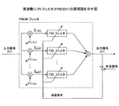
受信信号から他システムの干渉信号を除去する別の手法は、分数間隔等化器(FSE:Fractionally Spaced Equalizer)及び周波数シフトフィルタ(FRESH:FREquency SHift filtering)を用いることである。図6はFRESHの概略図を示す。図7はFSEの概略図を示す。FSEやFRESHは、図1の適応フィルタとして使用することができる。図6に示されるように、FRESHは並列に接続された複数のFSEを含み、それらFSEの出力は合成される。合成後の出力はトレーニング信号から引かれ、誤差信号が生成される。この誤差信号が小さくなるように、FSEの各フィルタ係数が調整される。図7に示されるように、FSEは、そこに入力されるオーバーサンプルされた信号を遅延させる一連の遅延要素群を有し、各々の出力に係数又はウエイトciを乗算して合成する。この一群の係数はタップ係数とも呼ばれる(FRESH及びFSEについては、非特許文献1,2参照。)。
上記の従来技術では、図1の送信フィルタ1,受信フィルタ3の特性は、それらが対をなして整合フィルタを形成するようにシステム設計時に固定的に決定され、チャネル変動に対する補償のような動的な補償は専ら適応フィルタに委ねられている。従って、干渉状況によっては干渉除去能力が不足してしまうことが懸念される。特に、非所望信号のパラメータが未知であって、所望信号のキャリア周波数と非所望信号のキャリア周波数の間隔が接近すればするほど、干渉の抑圧が困難になる。
In the above-described prior art, the characteristics of the
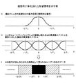
ところで、帯域制限を行うパルス整形フィルタ(図1のフィルタ1,2及び3)の特性は、パルス送信間隔及びパルス幅により規定される。パルス送信間隔(Ts)はシンボルレート(すなわちナイキスト帯域幅)(1/Ts)に反比例する関係を有する。パルス幅はパルス成形フィルタ帯域幅に反比例する関係を有する。図8に示されるように、パルス整形フィルタ帯域幅はナイキスト帯域幅と余剰帯域幅(Excess Bandwidth)で規定され、ナイキスト帯域幅はシンボルレート(1/Ts)で規定される。余剰帯域幅はパルス成形フィルタ帯域幅からナイキスト帯域幅を差し引いたものとなる。余剰帯域幅はナイキスト帯域幅に対する百分率で表現される。例えばパルス成形フィルタ帯域幅が2.4/Tsであり、ナイキスト帯域幅が1/Tsであったならば、余剰帯域幅は140%になる(図8左)。ナイキスト帯域幅が2/Tsであったならば、余剰帯域幅は20%になる(図8右)。ナイキスト帯域幅が広ければそれだけ情報伝送量を増やすことができるので、余剰帯域は小さく固定されているのが一般的である。しかしながら余剰帯域が小さいと、自システムの帯域内の干渉に対してFRESH及びFSEによる干渉除去能力も小さくなってしまう。
By the way, the characteristics of the pulse shaping filters (
更に、所望信号の帯域の中で干渉信号の占める割合や、所望信号に隣接するチャネルの空き状況等は通信状況に応じて刻々と変化する。従って干渉除去能力も通信状況に応じて変動し、場合によってはそれが不足してしまうことも懸念される。その結果、スループットが急激に劣化するおそれもある。 Furthermore, the ratio of the interference signal in the band of the desired signal, the availability of the channel adjacent to the desired signal, and the like change every moment according to the communication situation. Therefore, the interference removal capability varies depending on the communication status, and there is a concern that it may become insufficient in some cases. As a result, the throughput may deteriorate rapidly.
本発明は、上記問題点の少なくとも1つに対処するためになされたものであり、その課題は、複数のシステムが同一の周波数帯域で通信を行う周波数共存環境において、他システムからの干渉信号のパラメータが既知でなくても自システムでの受信特性の劣化を軽減させ、結果的にスループットを向上できる通信装置及び通信方法を提供することである。 The present invention has been made to address at least one of the above-described problems, and its problem is to solve the problem of interference signals from other systems in a frequency coexistence environment where a plurality of systems communicate in the same frequency band. To provide a communication device and a communication method capable of reducing the deterioration of reception characteristics in the own system and improving the throughput as a result even if the parameter is not known.
本発明による通信装置は、複数の通信システムが同一の周波数帯域で通信を行う周波数共存環境で使用される。通信装置は、送信シンボルを表すパルスの帯域制限を行う送信パルス整形手段と、自装置が所属するシステムとは異なる他システムからの干渉状況及び自システムの空きチャネル状況を監視する監視手段と、送信パルス整形手段で使用されるパルス送信間隔及びパルス幅を制御する制御手段と、帯域制限後の信号を送信する手段とを有することを特徴とする。 The communication apparatus according to the present invention is used in a frequency coexistence environment in which a plurality of communication systems communicate in the same frequency band. The communication apparatus includes a transmission pulse shaping means for limiting a band of a pulse representing a transmission symbol, a monitoring means for monitoring an interference situation from another system different from a system to which the own apparatus belongs and an empty channel situation of the own system, and a transmission It has a control means for controlling the pulse transmission interval and pulse width used in the pulse shaping means, and means for transmitting a signal after band limitation.
本発明によれば、複数のシステムが同一の周波数帯域で通信を行う周波数共存環境において、干渉状況と隣接チャネルの空き状況を監視し、自システムのパルス整形フィルタ帯域幅及びシンボルレートを調整することで、自システムの余剰帯域幅を調整でき、他システムからの干渉信号のパラメータが既知でなくても自システムでのスループットの劣化を軽減することができる。 According to the present invention, in a frequency coexistence environment in which a plurality of systems communicate in the same frequency band, the interference status and the vacant status of adjacent channels are monitored, and the pulse shaping filter bandwidth and symbol rate of the own system are adjusted. Thus, it is possible to adjust the surplus bandwidth of the own system and to reduce the degradation of the throughput in the own system even if the parameters of interference signals from other systems are not known.
本発明の一形態によれば、干渉状況と隣接チャネルの空き状況に応じてパルス整形フィルタ帯域幅及び/又はシンボルレートが適応的に調整され、自システムの余剰帯域幅がスループットが向上するように制御がなされる。余剰帯域が小さくナイキスト帯域幅が大きい場合には、より多くの帯域が情報伝送に使用されるので、帯域の利用効率は良い。しかしながら、この場合に他システムからの干渉が生じると、スループットは大幅に劣化してしまう。 According to an aspect of the present invention, the pulse shaping filter bandwidth and / or symbol rate is adaptively adjusted according to interference conditions and adjacent channel availability, so that the surplus bandwidth of the own system improves throughput. Control is made. When the surplus bandwidth is small and the Nyquist bandwidth is large, more bandwidth is used for information transmission, so the bandwidth utilization efficiency is good. However, if interference from other systems occurs in this case, the throughput is greatly degraded.
本発明の一形態では、チャネル状態が悪化した場合に余剰帯域を増やし、FSEやFRESHフィルタで効果的に干渉を除去する。パルス整形フィルタに使用されるシンボルレート及び/又はパルス成形フィルタ帯域幅を調整することで、余剰帯域を制御することができる。例えば、通信中にスループットが劣化した場合に、隣接チャネルに空きが有れば、シンボルレートをそのまま維持し、空きチャネルの帯域までパルス成形フィルタ帯域幅を拡張し、余剰帯域を増やし、干渉除去能力を向上させてもよい。このようにすると、シンボルレートを下げずにスループットを回復させることができる。一方、隣接チャネルに空きが無ければ、シンボルレートを減らしてナイキスト帯域幅を狭め、相対的に余剰帯域を増やしてもよい。例えばシンボルレート(2/Ts)を半分にすれば余剰帯域幅はその分だけ増える(1/Tsだけ増える)。このように余剰帯域幅を意図的に増やすことで、干渉除去能力を向上させることができ、自システムのスループットを向上させることができる。上記の例ではシンボルレート及びパルス成形フィルタ帯域幅の一方が固定され他方が調整されたが、双方共に調整されてもよい。 In one embodiment of the present invention, when the channel condition deteriorates, the surplus band is increased, and interference is effectively removed by the FSE or FRESH filter. The surplus band can be controlled by adjusting the symbol rate and / or the pulse shaping filter bandwidth used for the pulse shaping filter. For example, if the throughput deteriorates during communication and there is a vacancy in the adjacent channel, the symbol rate is maintained as it is, the pulse shaping filter bandwidth is expanded to the bandwidth of the vacant channel, the surplus bandwidth is increased, and the interference removal capability May be improved. In this way, throughput can be recovered without lowering the symbol rate. On the other hand, if there is no space in the adjacent channel, the Nyquist bandwidth may be narrowed by reducing the symbol rate, and the surplus bandwidth may be relatively increased. For example, if the symbol rate (2 / Ts) is halved, the surplus bandwidth increases by that amount (increases by 1 / Ts). By intentionally increasing the surplus bandwidth in this way, it is possible to improve the interference removal capability and improve the throughput of the own system. In the above example, one of the symbol rate and the pulse shaping filter bandwidth is fixed and the other is adjusted, but both may be adjusted.
本発明の一形態によれば、干渉状況によって送受信フィルタが適応的に変更され、受信機の干渉除去能力が大きく維持される。通信装置は伝達特性の中心周波数がそれぞれ異なる複数のフィルタと、複数のフィルタの出力及び既知信号に基づいて1以上のフィルタのフィルタ係数を適応的に調整する手段とを有してもよい。複数のフィルタの伝達特性の中心周波数は、基準となるフィルタに対してナイキスト帯域幅分(サイクリック周波数)だけ離れていてもよい。サイクリック周波数だけ中心周波数のずれたフィルタの出力は互いに大きな相関を有する。その相関値が大きくなるように(既知信号との差分が小さくなるように)フィルタ係数を適応的に更新することで、干渉の抑圧された受信信号を得ることができる。 According to an aspect of the present invention, the transmission / reception filter is adaptively changed according to the interference state, and the interference cancellation capability of the receiver is largely maintained. The communication apparatus may include a plurality of filters having different center frequencies of transfer characteristics and means for adaptively adjusting filter coefficients of one or more filters based on outputs of the plurality of filters and known signals. The center frequencies of the transfer characteristics of the plurality of filters may be separated from the reference filter by the Nyquist bandwidth (cyclic frequency). The outputs of the filters whose center frequencies are shifted by the cyclic frequency have a large correlation with each other. By adaptively updating the filter coefficient so that the correlation value becomes large (so that the difference from the known signal becomes small), a reception signal in which interference is suppressed can be obtained.
(送信側の処理)
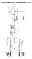
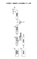
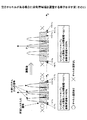
図9は、本発明の一実施例で使用される通信装置の送信部のブロック図を示す。図9には、送信系列生成部91、パルス整形部92、D/A変換器93、ミキサ94、増幅器95、アンテナ96、監視部97及び制御部98を有する。送信系列生成部91は図2(A)に示されるようなベースバンドの送信信号のデータ系列を生成する。パルス整形部92は送信信号を帯域制限し、パルス整形フィルタと呼ばれてもよい。より具体的にはパルス整形部92はそこに入力されたデータ系列の帯域制限を行い、設定済みのパルス幅及びパルス送信間隔で出力する。パルス整形フィルタの特性は制御部98により調整される。上述したように、パルス幅はパルス整形フィルタ92の帯域幅に逆比例し、パルス送信間隔はシンボルレートに逆比例する。D/A変換器93はベースバンドのディジタル信号をアナログ信号に変換する。ミキサ94は所望信号の搬送波(キャリア周波数f1)により周波数変換を行う。増幅器95は信号をアンテナ96から送信できるように信号の電力を増幅する。
(Sender processing)
FIG. 9 shows a block diagram of a transmission unit of a communication apparatus used in an embodiment of the present invention. 9 includes a transmission
監視部97は、自システムの帯域に含まれる干渉信号の周波数スペクトルや電力を監視することに加えて、その帯域に隣接する周波数での空き状況も監視する。空き状況も周波数スペクトルや電力を測定することで監視することができる。干渉状況又は空き状況の監視(又は観測)は、広帯域にわたるスペクトルをスキャンすることによってなされてもよい。或いは、そのようなスキャン以外の何らかの手法で干渉状況や空き状況に関する情報が取得されてもよい。
In addition to monitoring the frequency spectrum and power of the interference signal included in the band of the own system, the
制御部98は、監視された内容に基づいて、パルス整形フィルタ92で使用されるパルス幅(又はシンボルレート)及びパルス送信間隔(又はパルス成形フィルタ帯域幅)を決定し、決定内容をパルス整形フィルタ92に通知する。上述したように通信中の帯域制限は送信側と受信側の双方で行われ、ここでは送信側に関する内容がパルス整形フィルタ92に通知される。受信側に関する内容は制御チャネル等を通じて通信相手に通知される。スペクトルのスキャンが行われる場合の帯域制限は、スペクトルの幅に応じて行われる。
Based on the monitored content, the
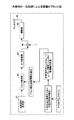
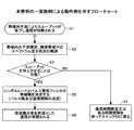
図10,11を参照しながら送信部の動作が説明される。図10は、自システムでの帯域内干渉状況と隣接チャネルの空き状況とを測定し、パルス整形部92のパラメータを決定する様子をより具体的に示す。そのパラメータにはパルス幅とパルス送信間隔が少なくとも含まれる。図11は本実施例による送信部の動作例を示すフローチャートである。
The operation of the transmission unit will be described with reference to FIGS. FIG. 10 shows in more detail how the parameters of the
ステップS1では、ある移動局(又は基地局)が通信していたところ、干渉信号が増大して通信が妨げられてしまった状況が仮定されている。便宜上、その移動局(基地局)が属するシステムは自システム又は所望システムと呼ばれ、それ以外のシステムは他システムと呼ばれる。説明の便宜上、通信が切断されてしまった状態が想定されているが、本発明はそのような状況だけでなく、干渉を抑制することが必要な様々な状況で使用可能である。 In step S1, it is assumed that when a certain mobile station (or base station) is communicating, an interference signal increases and communication is hindered. For convenience, the system to which the mobile station (base station) belongs is called the own system or the desired system, and other systems are called other systems. For convenience of explanation, it is assumed that the communication has been disconnected. However, the present invention can be used not only in such a situation but also in various situations where interference needs to be suppressed.
このような状況で通信を再開するために別のチャネルを使用することが考えられる。しかしながらそのようにするとすれば、干渉信号の中心周波数が動的に変動する場合には、それに合わせて通信の周波数も動的に変えなければならなくなる。従ってこのような手法はシステムに過剰な処理負担を強いることになり、得策ではない。更に自システムでの通信の周波数を変えることで干渉が回避されるとしても、自他のシステムで使用される帯域の間にガードバンドを設ける必要があるので、この手法は周波数利用効率の観点からも得策ではない。 It is conceivable to use another channel to resume communication in such a situation. However, if this is done, if the center frequency of the interference signal changes dynamically, the communication frequency must be changed dynamically accordingly. Therefore, such a method imposes an excessive processing burden on the system and is not a good idea. Furthermore, even if interference is avoided by changing the frequency of communication in the own system, it is necessary to provide a guard band between the bands used in the other system, so this method is used from the viewpoint of frequency utilization efficiency. Is not a good idea.
ステップS2では、監視部97で干渉状況及び隣接帯域の空き状況が測定される。例えば、送信部(監視部97)は、自身の信号送信を一時的に停止し、受信した他システムの信号の強度及び周波数等を測定することで、そのような状況を測定してもよい。
In step S <b> 2, the
ステップS3では、制御部98が、干渉状況及び空き状況に基づいて、干渉を抑制してスループットを改善できる可能性の有無を判定する。判定結果が否定的であったならば(Noの場合)、フローはステップS4に進む。ステップS4では、信号の送信を中止する、一定時間経過後にステップS2に戻る、或いは他システムに干渉信号の送信中止を求める等の対策が講じられる。ステップS3の判定結果が肯定的であったならば(Yesの場合)、フローはステップS5に進む。
In step S <b> 3, the
ステップS5では、決定されたパラメータ(パルス幅及びパルス送信間隔)が、パルス整形部92に設定される。
In step S <b> 5, the determined parameters (pulse width and pulse transmission interval) are set in the
ステップS6では、調整後のパルス整形部92で帯域制限された信号が送信され、通信が再開される。
In step S6, the band-limited signal is transmitted by the adjusted
(受信側の処理)
送信された信号は受信機で受信され、適切に帯域制限及び干渉除去がなされ、送信された信号が復元される。受信機には図6に示されるような周波数シフトフィルタ(FRESHフィルタ)が備えられる。本実施例における周波数シフトフィルタは適応フィルタとして機能する。受信機は、適切に設定された余剰帯域を利用して他システムからの干渉を抑制する。後述されるように所望信号が有する余剰帯域を利用することによって、干渉信号を効果的に抑制することができる。
(Receiver processing)
The transmitted signal is received by the receiver, and band limitation and interference removal are appropriately performed, and the transmitted signal is restored. The receiver is provided with a frequency shift filter (FRESH filter) as shown in FIG. The frequency shift filter in this embodiment functions as an adaptive filter. The receiver uses an appropriately set surplus band to suppress interference from other systems. As described later, the interference signal can be effectively suppressed by using the surplus band of the desired signal.
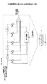
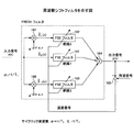
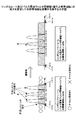
図12は受信側で使用される周波数シフトフィルタの一例を示す。周波数シフトフィルタは、3系統に分岐した経路と、各経路からの信号を合成する合成部164と、合成部の出力信号及び所望信号(例えば、トレーニング信号)の差分を出力する誤差信号生成部165とを有する。分岐した経路1,2,3にはそれぞれ、FSEフィルタ161,162,163が設けられ、経路2,3には更に位相回転量を調整する位相調整部167,168が設けられている。FSEフィルタ161,162,163の各々は図7に示されるような構成及び機能を有する。経路2の位相調整部167は入力信号x(t)の中心周波数をナイキスト帯域幅分(1/T1)だけマイナス方向にシフトさせる。経路3の位相調整部168は入力信号x(t)の中心周波数をナイキスト帯域幅分(1/T1)だけプラス方向にシフトさせる。
FIG. 12 shows an example of a frequency shift filter used on the receiving side. The frequency shift filter includes a path branched into three systems, a
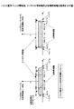
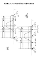
図13は、合成部164による合成前の経路1及び経路2での信号のスペクトルを示す。実線の波形は所望信号に関連し、破線の波形は干渉信号に関連する。経路2の位相調整部167は入力信号x(t)の中心周波数を(1/T1)だけマイナス方向にシフトさせる。従って、経路2での信号のスペクトルは、図13上側に示される波形を、同図下側に示されるように、周波数軸方向に1/T1だけずらしたものになる。所望信号は余剰帯域を有するために、1/T1だけずれた所望信号と大きな相関をもたらすが、1/T1だけ互にずれた干渉信号の相関は小さくなる。1/T1はサイクリック周波数とも呼ばれる。従って、FSEフィルタ161,162からの信号は合成後に、抑制された干渉を含む信号になる。
FIG. 13 shows the spectrum of the signal in the
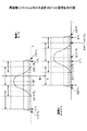
図14は、図13と同様であるが、経路1と経路3の信号のスペクトルを示す。経路3でのスペクトルは、図14上側に示される波形を、同図下側に示されるように、経路2とのものは逆方向に1/T1だけずらしたものになる。同様にして、所望信号は1/T1だけずれた所望信号と大きな相関をもたらす。従って、FSEフィルタ161,163からの信号も合成後に、抑圧された干渉を含む信号になる。
FIG. 14 is similar to FIG. 13 but shows the spectrum of the signals of
合成部164からの出力信号は、誤差信号生成部165に入力される。誤差信号生成部165は、出力信号と所望信号(トレーニング信号)との差分を誤差信号として出力する。この誤差信号が小さくなるように、各FSEフィルタ161,162,163のフィルタ係数がそれぞれ適応的に更新され、以下同様な動作が反復される。誤差信号生成部165からの出力信号が十分に小さな信号になるように各FSEフィルタの係数が調整できれば、干渉信号の影響は十分に抑制可能である。このように所望信号が有する余剰帯域を利用することによって、効果的に干渉信号を抑制することができる。
The output signal from the
図13,14に示される例では、図8の左側に示される余剰帯域幅140%のパルスを用いる場合について図示されたが、その代わりにルートレイズドコサインフィルタ等が使用されてもよい。どのようなフィルタが使用されるにせよ、余剰帯域を活用することで他システムからの干渉を抑制することができればよい。但し、図13,14に示されるようなパルスが使用される場合は、ナイキスト帯域を超える周波数領域でも比較的大きな振幅特性が得られ、ルートレイズドコサインフィルタの場合よりも図12の経路1と経路2の相関及び経路1と経路3の相関が大きくなるので、より効果的に干渉を除去することができる。そのような観点からは、例えば、ナイキスト帯域幅1/(T1)を超える周波数領域で、より大きな振幅特性を示すフィルタが使用されてもよい。図12〜図14では互に中心周波数のずれた3系統の信号が合成部164で合成される処理が説明されたが、干渉信号のサイクリック周波数だけプラス及びマイナスにシフトした系統を加えた5系統が用意されてもよく、適切な系統はいくつでも用意されてよい。
In the example shown in FIGS. 13 and 14, the case where the pulse having the surplus bandwidth of 140% shown on the left side of FIG. 8 is used is illustrated, but a root raised cosine filter or the like may be used instead. Whatever filter is used, it is sufficient that interference from other systems can be suppressed by utilizing the surplus bandwidth. However, when a pulse as shown in FIGS. 13 and 14 is used, a relatively large amplitude characteristic is obtained even in a frequency region exceeding the Nyquist band, and the
上述したように本発明による通信装置は帯域内の干渉状況及び隣接帯域の空き状況を監視し、監視内容に応じてパルス整形フィルタに使用されるパルス幅及びパルス送信間隔等のパラメータが決定及び設定され、干渉が抑制される。以下、いくつかの想定例が列挙され、各想定例でパラメータがどのように決定されるかが説明される。概してこれらの想定例は隣接帯域に空きチャネルが有るか否かで大別される。 As described above, the communication apparatus according to the present invention monitors the interference state in the band and the vacant state of the adjacent band, and parameters such as the pulse width and the pulse transmission interval used for the pulse shaping filter are determined and set according to the monitoring contents. Interference is suppressed. In the following, several assumption examples are listed and how parameters are determined in each assumption example will be described. In general, these assumptions are roughly classified according to whether or not there is an empty channel in the adjacent band.
(1)隣接帯域に空きチャネルがない場合
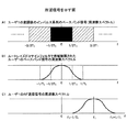
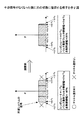
図15は隣接帯域に空きチャネルがない場合であって干渉信号が強くなったときに、パルス成形帯域幅を一定にしつつシンボルレートを下げることで干渉を抑制する例が示されている。パラメータ調整前の状況では、シンボルレートが2/Tsであり、パルス成形帯域幅が2.4/Tsであり、余剰帯域幅が20%である。パラメータ調整後では、シンボルレートが1/Tsに減り、パルス成形帯域幅は2.4/Tsで不変であり、余剰帯域幅は140%に増えている。このようにして相対的に増やされた余剰帯域を用いて受信信号中の干渉が抑制される。シンボルレートをどの程度減らしてよいかは通信状況やサービス品質によって異なるが、干渉信号を抑制する観点からは、シンボルレート変更後のナイキスト帯域幅が干渉信号の占める帯域幅以上であればよい。
(1) When there is no empty channel in the adjacent band FIG. 15 shows a case where there is no empty channel in the adjacent band, and when the interference signal becomes strong, interference is reduced by reducing the symbol rate while keeping the pulse shaping bandwidth constant. An example of suppression is shown. In the situation before parameter adjustment, the symbol rate is 2 / Ts, the pulse shaping bandwidth is 2.4 / Ts, and the surplus bandwidth is 20%. After parameter adjustment, the symbol rate decreases to 1 / Ts, the pulse shaping bandwidth remains unchanged at 2.4 / Ts, and the surplus bandwidth increases to 140%. In this way, interference in the received signal is suppressed by using the surplus band relatively increased. How much the symbol rate can be reduced depends on the communication status and service quality, but from the viewpoint of suppressing the interference signal, the Nyquist bandwidth after changing the symbol rate may be equal to or greater than the bandwidth occupied by the interference signal.
図16は図15と逆の場合に相当し、干渉信号がなくなった後に元の状態に復旧する様子が示される。干渉信号がなくなっているので、干渉抑制能力は元の低いレベルに落とされてもよい。この場合も空きチャネルはないことが仮定されている。シンボルレートは2/Tsに増やされ、パルス成形帯域幅は2.4/Tsのままであり、余剰帯域幅は20%に減らされる。 FIG. 16 corresponds to the reverse case of FIG. 15 and shows a state where the original state is restored after the interference signal disappears. Since the interference signal is gone, the interference suppression capability may be reduced to the original low level. Again, it is assumed that there are no free channels. The symbol rate is increased to 2 / Ts, the pulse shaping bandwidth remains 2.4 / Ts, and the surplus bandwidth is reduced to 20%.
(2)隣接帯域に空きチャネルがある場合(その1)
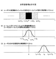
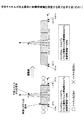
図17は隣接帯域に空きチャネルが存在する場合であって干渉信号が強くなったときに、シンボルレートを一定にしつつ空きチャネルの帯域を余剰帯域として使用する例を示す。パラメータ調整前の状況では、シンボルレートが2/Tsであり、パルス成形帯域幅が2.4/Tsであり、余剰帯域幅が20%である。パラメータ調整後では、シンボルレートは2/Tsに維持され、パルス成形帯域幅は4.4/Tsに拡張され、余剰帯域幅は120%に増えている。このようにして絶対的に増やされた余剰帯域を用いて受信信号中の干渉が抑制される。この手法では、理論的には空きチャネルが有る限り余剰帯域を広げることにより、干渉構成能力を向上させることができる。
(2) When there is an empty channel in the adjacent band (part 1)
FIG. 17 shows an example in which a free channel band is used as a surplus band while a symbol rate is constant when a free channel exists in an adjacent band and an interference signal becomes strong. In the situation before parameter adjustment, the symbol rate is 2 / Ts, the pulse shaping bandwidth is 2.4 / Ts, and the surplus bandwidth is 20%. After parameter adjustment, the symbol rate is maintained at 2 / Ts, the pulse shaping bandwidth is expanded to 4.4 / Ts, and the surplus bandwidth is increased to 120%. In this way, interference in the received signal is suppressed using the surplus band that is absolutely increased. In this method, theoretically, it is possible to improve the interference configuration capability by expanding the surplus bandwidth as long as there is an empty channel.
(3)隣接帯域に空きチャネルがある場合(その2)
図18も隣接帯域に空きチャネルが存在する場合であって干渉信号が強くなったときに、シンボルレートを一定にしつつ空きチャネルの帯域を余剰帯域として使用する例を示す。図示の例では干渉信号の占める帯域幅がナイキスト帯域幅よりも多い。また、空きチャネルの量が図17の場合よりも少ない。この場合も、余剰帯域幅を空きチャネルに合わせて拡張することで干渉を抑制することができる。図示の例ではパラメータ調整後に、シンボルレートは1/Tsに維持され、パルス成形帯域幅は3.2/Tsに拡張され、余剰帯域幅は220%に増えている。
(3) When there is an empty channel in the adjacent band (part 2)
FIG. 18 also shows an example in which a free channel band is used as a surplus band while a symbol rate is constant when a free channel exists in an adjacent band and an interference signal becomes strong. In the illustrated example, the bandwidth occupied by the interference signal is larger than the Nyquist bandwidth. Also, the amount of free channels is smaller than in the case of FIG. Also in this case, interference can be suppressed by extending the surplus bandwidth in accordance with the empty channel. In the illustrated example, after parameter adjustment, the symbol rate is maintained at 1 / Ts, the pulse shaping bandwidth is expanded to 3.2 / Ts, and the surplus bandwidth is increased to 220%.
(4)隣接帯域に空きチャネルがあり、シンボルレート及びパルス成形帯域幅(パルス整形フィルタ帯域幅)の双方を変更する場合
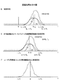
図19は隣接帯域に空きチャネルが存在する場合であって干渉信号が強くなったときに、シンボルレートを増やし且つ空きチャネルの帯域を余剰帯域として使用する例を示す。パラメータ調整前の状況では、シンボルレートが1/Tsであり、パルス成形帯域幅が2.4/Tsであり、余剰帯域幅が140%である。パラメータ調整後では、シンボルレートは2/Tsに増やされ、パルス成形帯域幅は4.4/Tsに拡張され、余剰帯域幅は120%になっている。これにより、シンボルレートの増加と、干渉除去能力の向上を同時に実現することができる。
(4) When there is an empty channel in the adjacent band and both the symbol rate and the pulse shaping bandwidth (pulse shaping filter bandwidth) are changed. FIG. 19 shows a case where there is an empty channel in the adjacent band and the interference signal is strong. In this example, the symbol rate is increased and the band of the empty channel is used as the surplus band. In the situation before parameter adjustment, the symbol rate is 1 / Ts, the pulse shaping bandwidth is 2.4 / Ts, and the surplus bandwidth is 140%. After parameter adjustment, the symbol rate is increased to 2 / Ts, the pulse shaping bandwidth is expanded to 4.4 / Ts, and the surplus bandwidth is 120%. Thereby, an increase in symbol rate and an improvement in interference removal capability can be realized at the same time.
91 送信系列生成部
92 パルス整形部
93 D/A変換器
94 ミキサ
95 増幅器
96 アンテナ
97 監視部
98 制御部
161,162,163 FSEフィルタ
164 合成部
165 誤差信号生成部
167,168 位相調整部
91 Transmission
Claims (9)
送信シンボルのパルスの帯域制限を行う送信パルス整形手段と、
自装置が所属するシステムとは異なる他システムからの干渉状況及び自システムの空きチャネル状況を監視する監視手段と、
送信パルス整形手段で使用されるパルス送信間隔及びパルス幅を制御する制御手段と、
帯域制限後の信号を送信する手段と、
を有することを特徴とする通信装置。 A communication device used in a frequency coexistence environment in which a plurality of communication systems communicate in the same frequency band,
Transmission pulse shaping means for limiting the band of the pulse of the transmission symbol;
Monitoring means for monitoring the interference status from other systems different from the system to which the own device belongs and the free channel status of the own system;
Control means for controlling the pulse transmission interval and pulse width used in the transmission pulse shaping means;
Means for transmitting a band-limited signal;
A communication apparatus comprising:
ことを特徴とする請求項1記載の通信装置。 The communication apparatus according to claim 1, wherein the control unit changes both or one of the pulse transmission interval and the pulse width according to the interference state and the idle channel state.
を更に有することを特徴とする請求項1記載の通信装置。 The communication apparatus according to claim 1, further comprising reception pulse shaping means for limiting a band of the reception signal.
ことを特徴とする請求項2記載の通信装置。 The apparatus according to claim 2, further comprising: a plurality of filters having different center frequencies of transfer characteristics; and means for adaptively adjusting filter coefficients of the one or more filters based on outputs of the plurality of filters and known signals. The communication device described.
ことを特徴とする請求項2記載の通信装置。 The communication device according to claim 2, wherein center frequencies of transfer characteristics of the plurality of filters are separated by a Nyquist bandwidth of the own system.
ことを特徴とする請求項2記載の通信装置。 The communication device according to claim 2, wherein each of the plurality of filters is a filter that passes a band that is twice or more the Nyquist bandwidth of the own system.
自装置が所属するシステムとは異なる他システムからの干渉状況及び自システムの空きチャネル状況を監視し、
前記監視状況及び前記空きチャネル状況に応じて決定されたパルス送信間隔及びパルス幅を送信パルス整形手段に設定し、
前記送信パルス整形手段を用いて、送信シンボルを表すパルスの帯域制限を行い、
帯域制限後の信号を送信する
ことを特徴とする通信方法。 A communication method used in a frequency coexistence environment in which a plurality of communication systems communicate in the same frequency band,
Monitor the interference status from other systems different from the system to which the device belongs and the free channel status of the own system.
Set the pulse transmission interval and pulse width determined according to the monitoring status and the empty channel status in the transmission pulse shaping means,
Using the transmission pulse shaping means, band limitation of the pulse representing the transmission symbol,
A communication method characterized by transmitting a signal after band limitation.
ことを特徴とする請求項7記載の通信方法。 The communication method according to claim 7, wherein when there is no predetermined amount of free channels and there is an interference amount from another system, the transmission pulse interval is widened but the pulse width is maintained.
ことを特徴とする請求項7記載の通信方法。 The communication method according to claim 7, wherein when the amount of interference from another system decreases, the pulse interval is narrowed with an upper limit of a band that can be occupied by the own system.
Priority Applications (4)
| Application Number | Priority Date | Filing Date | Title |
|---|---|---|---|
| JP2005360920A JP4711819B2 (en) | 2005-12-14 | 2005-12-14 | Communication apparatus and communication method |
| EP06256342A EP1798865B1 (en) | 2005-12-14 | 2006-12-13 | Communication apparatus and communication method used in spectrum sharing environment |
| US11/610,767 US8014464B2 (en) | 2005-12-14 | 2006-12-14 | Communication apparatus and communication method used in spectrum sharing environment |
| CN2006101670913A CN1983829B (en) | 2005-12-14 | 2006-12-14 | Communication apparatus and communication method |
Applications Claiming Priority (1)
| Application Number | Priority Date | Filing Date | Title |
|---|---|---|---|
| JP2005360920A JP4711819B2 (en) | 2005-12-14 | 2005-12-14 | Communication apparatus and communication method |
Publications (2)
| Publication Number | Publication Date |
|---|---|
| JP2007166324A true JP2007166324A (en) | 2007-06-28 |
| JP4711819B2 JP4711819B2 (en) | 2011-06-29 |
Family
ID=37943808
Family Applications (1)
| Application Number | Title | Priority Date | Filing Date |
|---|---|---|---|
| JP2005360920A Expired - Lifetime JP4711819B2 (en) | 2005-12-14 | 2005-12-14 | Communication apparatus and communication method |
Country Status (4)
| Country | Link |
|---|---|
| US (1) | US8014464B2 (en) |
| EP (1) | EP1798865B1 (en) |
| JP (1) | JP4711819B2 (en) |
| CN (1) | CN1983829B (en) |
Cited By (3)
| Publication number | Priority date | Publication date | Assignee | Title |
|---|---|---|---|---|
| US8437762B2 (en) | 2008-08-20 | 2013-05-07 | Qualcomm Incorporated | Adaptive transmission (Tx)/reception (Rx) pulse shaping filter for femtocell base stations and mobile stations within a network |
| US8452332B2 (en) | 2008-08-20 | 2013-05-28 | Qualcomm Incorporated | Switching between different transmit/receive pulse shaping filters for limiting adjacent channel interference |
| KR101310721B1 (en) * | 2009-08-11 | 2013-09-24 | 퀄컴 인코포레이티드 | Adaptive transmission (tx)/reception (rx) pulse shaping filter for femtocell base stations and mobile stations within a network |
Families Citing this family (6)
| Publication number | Priority date | Publication date | Assignee | Title |
|---|---|---|---|---|
| GB0721307D0 (en) * | 2007-10-30 | 2007-12-12 | Nokia Siemens Networks Oy | Measuring apparatus |
| JP5251851B2 (en) * | 2009-12-03 | 2013-07-31 | 富士通株式会社 | Impulse wireless communication device |
| US9021121B2 (en) | 2011-06-17 | 2015-04-28 | Lenovo (Singapore) Pte. Ltd. | Setting a rate of data transmission in a peer-to-peer mode |
| EP2995108B1 (en) | 2013-05-10 | 2018-01-03 | Nokia Solutions and Networks Oy | Communication mechanism using co-primary spectrum sharing |
| US9407472B1 (en) * | 2014-06-18 | 2016-08-02 | Seagate Technology Llc | Fast transversal multi-input system |
| US12143133B2 (en) * | 2021-07-22 | 2024-11-12 | Qualcomm Incorporated | Dynamic shaping filter indications |
Citations (5)
| Publication number | Priority date | Publication date | Assignee | Title |
|---|---|---|---|---|
| JPH10242931A (en) * | 1997-01-08 | 1998-09-11 | Deutsche Thomson Brandt Gmbh | Wireless transmission method for digital multimedia data signals between subscriber stations in a local network |
| JPH11312928A (en) * | 1998-03-05 | 1999-11-09 | Lucent Technol Inc | Method and device for distortion for special use of signal before amplification |
| JP2000013342A (en) * | 1998-06-18 | 2000-01-14 | Omron Corp | Wireless transmitting device, wireless receiving device, and wireless communication system |
| WO2004077775A1 (en) * | 2003-02-25 | 2004-09-10 | Yokohama Tlo Company, Ltd. | Pulse waveform producing method |
| JP2004357285A (en) * | 2003-05-08 | 2004-12-16 | Matsushita Electric Ind Co Ltd | Impulse waveform generator |
Family Cites Families (13)
| Publication number | Priority date | Publication date | Assignee | Title |
|---|---|---|---|---|
| US7236754B2 (en) * | 1999-08-23 | 2007-06-26 | Parkervision, Inc. | Method and system for frequency up-conversion |
| KR100381002B1 (en) * | 2001-05-31 | 2003-04-23 | 에스케이 텔레콤주식회사 | Apparatus for removing of pulse interpolation in wireless communication system |
| EP1449397B1 (en) * | 2001-11-30 | 2005-06-15 | Telefonaktiebolaget LM Ericsson (publ) | Interference measurements in a wireless communications system |
| CA2379617C (en) * | 2002-03-28 | 2010-06-01 | The Governors Of The University Of Alberta | Methods, systems and devices for generating pulse shapes |
| US7283562B2 (en) * | 2002-09-26 | 2007-10-16 | International Business Machines Corporation | Method and apparatus for scaling input bandwidth for bandwidth allocation technology |
| US7317750B2 (en) * | 2002-10-31 | 2008-01-08 | Lot 41 Acquisition Foundation, Llc | Orthogonal superposition coding for direct-sequence communications |
| KR20050030756A (en) * | 2003-09-26 | 2005-03-31 | 유티스타콤코리아 유한회사 | Method and process for implementing wideband multicarrier |
| KR100656339B1 (en) * | 2003-12-26 | 2006-12-11 | 한국전자통신연구원 | Pulse signal generator for ultra-wide band radio transceiving and radio transceiver having the same |
| US7355997B2 (en) * | 2004-05-07 | 2008-04-08 | Cisco Technology, Inc. | Data rate shifting methods and techniques |
| JP4618082B2 (en) * | 2004-11-19 | 2011-01-26 | パナソニック株式会社 | Transmitting apparatus, receiving apparatus, and communication system |
| US7619971B1 (en) * | 2005-05-16 | 2009-11-17 | Extreme Networks, Inc. | Methods, systems, and computer program products for allocating excess bandwidth of an output among network users |
| US7652979B2 (en) * | 2005-12-08 | 2010-01-26 | University Of South Florida | Cognitive ultrawideband-orthogonal frequency division multiplexing |
| US7620095B2 (en) * | 2006-06-14 | 2009-11-17 | Vishay Intertechnology Inc | RF modem utilizing saw device with pulse shaping and programmable frequency synthesizer |
-
2005
- 2005-12-14 JP JP2005360920A patent/JP4711819B2/en not_active Expired - Lifetime
-
2006
- 2006-12-13 EP EP06256342A patent/EP1798865B1/en not_active Expired - Fee Related
- 2006-12-14 US US11/610,767 patent/US8014464B2/en not_active Expired - Fee Related
- 2006-12-14 CN CN2006101670913A patent/CN1983829B/en not_active Expired - Fee Related
Patent Citations (5)
| Publication number | Priority date | Publication date | Assignee | Title |
|---|---|---|---|---|
| JPH10242931A (en) * | 1997-01-08 | 1998-09-11 | Deutsche Thomson Brandt Gmbh | Wireless transmission method for digital multimedia data signals between subscriber stations in a local network |
| JPH11312928A (en) * | 1998-03-05 | 1999-11-09 | Lucent Technol Inc | Method and device for distortion for special use of signal before amplification |
| JP2000013342A (en) * | 1998-06-18 | 2000-01-14 | Omron Corp | Wireless transmitting device, wireless receiving device, and wireless communication system |
| WO2004077775A1 (en) * | 2003-02-25 | 2004-09-10 | Yokohama Tlo Company, Ltd. | Pulse waveform producing method |
| JP2004357285A (en) * | 2003-05-08 | 2004-12-16 | Matsushita Electric Ind Co Ltd | Impulse waveform generator |
Cited By (3)
| Publication number | Priority date | Publication date | Assignee | Title |
|---|---|---|---|---|
| US8437762B2 (en) | 2008-08-20 | 2013-05-07 | Qualcomm Incorporated | Adaptive transmission (Tx)/reception (Rx) pulse shaping filter for femtocell base stations and mobile stations within a network |
| US8452332B2 (en) | 2008-08-20 | 2013-05-28 | Qualcomm Incorporated | Switching between different transmit/receive pulse shaping filters for limiting adjacent channel interference |
| KR101310721B1 (en) * | 2009-08-11 | 2013-09-24 | 퀄컴 인코포레이티드 | Adaptive transmission (tx)/reception (rx) pulse shaping filter for femtocell base stations and mobile stations within a network |
Also Published As
| Publication number | Publication date |
|---|---|
| CN1983829B (en) | 2010-05-19 |
| CN1983829A (en) | 2007-06-20 |
| EP1798865B1 (en) | 2012-09-05 |
| US8014464B2 (en) | 2011-09-06 |
| EP1798865A3 (en) | 2012-01-04 |
| JP4711819B2 (en) | 2011-06-29 |
| US20070133712A1 (en) | 2007-06-14 |
| EP1798865A2 (en) | 2007-06-20 |
Similar Documents
| Publication | Publication Date | Title |
|---|---|---|
| JP4633189B2 (en) | COMMUNICATION SYSTEM, TRANSMISSION DEVICE, COMMUNICATION METHOD | |
| JP4614829B2 (en) | Communication apparatus and communication method | |
| US20070161361A1 (en) | Interference rejection in telecommunication system | |
| WO2007108997A2 (en) | Link quality prediction | |
| US5963599A (en) | Truncated maximum likelihood sequence estimator | |
| US9077410B2 (en) | Apparatus and method of transmitting data in multi-carrier system | |
| JP4711819B2 (en) | Communication apparatus and communication method | |
| CN101536337A (en) | Method and apparatus for efficient signal interpolation | |
| JPWO2007094154A1 (en) | Band limiting method and wireless communication system | |
| JP4774435B2 (en) | Doppler frequency estimation device, receiving device, program, and Doppler frequency estimation method | |
| JP5114551B2 (en) | Method and apparatus for canceling partially known interference using transmit diversity based interference cancellation | |
| JP2006115096A (en) | Multi-carrier communication apparatus and peak power suppression method | |
| KR100340197B1 (en) | Narrowband Interference Canceller System with Adaptive Compensation Filter and its Method in CDMA System | |
| JP4635750B2 (en) | Equalizer and equalization method | |
| JP2013236302A (en) | Mobile station device, base station device, transmission method, and wireless communication system | |
| WO2007007761A1 (en) | Receiving apparatus and receiving method | |
| KR100901046B1 (en) | Radio receiving apparatus and radio receiving method | |
| JPWO2007015317A1 (en) | Transmitter, receiver, communication method, and transmission / reception system | |
| KR200245068Y1 (en) | Narrowband Interference Canceller with Adaptive Compensation Filter in CDMA System | |
| EP1950897A1 (en) | Reception status information notifying method and reception status information notifying apparatus | |
| Yang et al. | Partial self-interference cancellation with frame pre-aliasing method for full-duplex DF system | |
| Sumithabhashini et al. | Reduction of Cochannel Interfernce in Global System For Mobile Communications | |
| KR20190071580A (en) | Method for communicating in in-band full duplex communication system | |
| HK1130373A (en) | Method and apparatus for efficient signal interpolation |
Legal Events
| Date | Code | Title | Description |
|---|---|---|---|
| A621 | Written request for application examination |
Free format text: JAPANESE INTERMEDIATE CODE: A621 Effective date: 20080926 |
|
| A977 | Report on retrieval |
Free format text: JAPANESE INTERMEDIATE CODE: A971007 Effective date: 20101213 |
|
| A131 | Notification of reasons for refusal |
Free format text: JAPANESE INTERMEDIATE CODE: A131 Effective date: 20110104 |
|
| A521 | Written amendment |
Free format text: JAPANESE INTERMEDIATE CODE: A523 Effective date: 20110224 |
|
| A01 | Written decision to grant a patent or to grant a registration (utility model) |
Free format text: JAPANESE INTERMEDIATE CODE: A01 Effective date: 20110322 |
|
| A61 | First payment of annual fees (during grant procedure) |
Free format text: JAPANESE INTERMEDIATE CODE: A61 Effective date: 20110322 |
|
| R250 | Receipt of annual fees |
Free format text: JAPANESE INTERMEDIATE CODE: R250 |
|
| R250 | Receipt of annual fees |
Free format text: JAPANESE INTERMEDIATE CODE: R250 |
|
| R250 | Receipt of annual fees |
Free format text: JAPANESE INTERMEDIATE CODE: R250 |
|
| R250 | Receipt of annual fees |
Free format text: JAPANESE INTERMEDIATE CODE: R250 |
|
| R250 | Receipt of annual fees |
Free format text: JAPANESE INTERMEDIATE CODE: R250 |
|
| R250 | Receipt of annual fees |
Free format text: JAPANESE INTERMEDIATE CODE: R250 |