JP4614829B2 - Communication apparatus and communication method - Google Patents
Communication apparatus and communication method Download PDFInfo
- Publication number
- JP4614829B2 JP4614829B2 JP2005179894A JP2005179894A JP4614829B2 JP 4614829 B2 JP4614829 B2 JP 4614829B2 JP 2005179894 A JP2005179894 A JP 2005179894A JP 2005179894 A JP2005179894 A JP 2005179894A JP 4614829 B2 JP4614829 B2 JP 4614829B2
- Authority
- JP
- Japan
- Prior art keywords
- signal
- filter
- frequency
- interference
- carrier frequency
- Prior art date
- Legal status (The legal status is an assumption and is not a legal conclusion. Google has not performed a legal analysis and makes no representation as to the accuracy of the status listed.)
- Expired - Fee Related
Links
Images


Classifications
-
- H—ELECTRICITY
- H04—ELECTRIC COMMUNICATION TECHNIQUE
- H04L—TRANSMISSION OF DIGITAL INFORMATION, e.g. TELEGRAPHIC COMMUNICATION
- H04L25/00—Baseband systems
- H04L25/02—Details ; arrangements for supplying electrical power along data transmission lines
- H04L25/03—Shaping networks in transmitter or receiver, e.g. adaptive shaping networks
- H04L25/03828—Arrangements for spectral shaping; Arrangements for providing signals with specified spectral properties
- H04L25/03834—Arrangements for spectral shaping; Arrangements for providing signals with specified spectral properties using pulse shaping
-
- H—ELECTRICITY
- H04—ELECTRIC COMMUNICATION TECHNIQUE
- H04B—TRANSMISSION
- H04B1/00—Details of transmission systems, not covered by a single one of groups H04B3/00 - H04B13/00; Details of transmission systems not characterised by the medium used for transmission
- H04B1/06—Receivers
- H04B1/10—Means associated with receiver for limiting or suppressing noise or interference
- H04B1/1027—Means associated with receiver for limiting or suppressing noise or interference assessing signal quality or detecting noise/interference for the received signal
- H04B1/1036—Means associated with receiver for limiting or suppressing noise or interference assessing signal quality or detecting noise/interference for the received signal with automatic suppression of narrow band noise or interference, e.g. by using tuneable notch filters
-
- H—ELECTRICITY
- H04—ELECTRIC COMMUNICATION TECHNIQUE
- H04B—TRANSMISSION
- H04B1/00—Details of transmission systems, not covered by a single one of groups H04B3/00 - H04B13/00; Details of transmission systems not characterised by the medium used for transmission
- H04B1/06—Receivers
- H04B1/10—Means associated with receiver for limiting or suppressing noise or interference
- H04B1/109—Means associated with receiver for limiting or suppressing noise or interference by improving strong signal performance of the receiver when strong unwanted signals are present at the receiver input
-
- H—ELECTRICITY
- H04—ELECTRIC COMMUNICATION TECHNIQUE
- H04J—MULTIPLEX COMMUNICATION
- H04J11/00—Orthogonal multiplex systems, e.g. using WALSH codes
- H04J11/0023—Interference mitigation or co-ordination
- H04J11/0026—Interference mitigation or co-ordination of multi-user interference
- H04J11/003—Interference mitigation or co-ordination of multi-user interference at the transmitter
-
- H—ELECTRICITY
- H04—ELECTRIC COMMUNICATION TECHNIQUE
- H04J—MULTIPLEX COMMUNICATION
- H04J11/00—Orthogonal multiplex systems, e.g. using WALSH codes
- H04J11/0023—Interference mitigation or co-ordination
- H04J11/005—Interference mitigation or co-ordination of intercell interference
-
- H—ELECTRICITY
- H04—ELECTRIC COMMUNICATION TECHNIQUE
- H04L—TRANSMISSION OF DIGITAL INFORMATION, e.g. TELEGRAPHIC COMMUNICATION
- H04L25/00—Baseband systems
- H04L25/02—Details ; arrangements for supplying electrical power along data transmission lines
- H04L25/03—Shaping networks in transmitter or receiver, e.g. adaptive shaping networks
- H04L25/03006—Arrangements for removing intersymbol interference
- H04L25/03012—Arrangements for removing intersymbol interference operating in the time domain
- H04L25/03019—Arrangements for removing intersymbol interference operating in the time domain adaptive, i.e. capable of adjustment during data reception
- H04L25/03038—Arrangements for removing intersymbol interference operating in the time domain adaptive, i.e. capable of adjustment during data reception with a non-recursive structure
- H04L25/03044—Arrangements for removing intersymbol interference operating in the time domain adaptive, i.e. capable of adjustment during data reception with a non-recursive structure using fractionally spaced delay lines or combinations of fractionally integrally spaced taps
-
- H—ELECTRICITY
- H04—ELECTRIC COMMUNICATION TECHNIQUE
- H04L—TRANSMISSION OF DIGITAL INFORMATION, e.g. TELEGRAPHIC COMMUNICATION
- H04L25/00—Baseband systems
- H04L25/02—Details ; arrangements for supplying electrical power along data transmission lines
- H04L25/03—Shaping networks in transmitter or receiver, e.g. adaptive shaping networks
- H04L25/03828—Arrangements for spectral shaping; Arrangements for providing signals with specified spectral properties
- H04L25/03834—Arrangements for spectral shaping; Arrangements for providing signals with specified spectral properties using pulse shaping
- H04L25/03853—Shaping by digital methods other than look up tables or up/down converters
-
- H—ELECTRICITY
- H04—ELECTRIC COMMUNICATION TECHNIQUE
- H04L—TRANSMISSION OF DIGITAL INFORMATION, e.g. TELEGRAPHIC COMMUNICATION
- H04L27/00—Modulated-carrier systems
- H04L27/26—Systems using multi-frequency codes
- H04L27/2601—Multicarrier modulation systems
- H04L27/2626—Arrangements specific to the transmitter only
- H04L27/2646—Arrangements specific to the transmitter only using feedback from receiver for adjusting OFDM transmission parameters, e.g. transmission timing or guard interval length
-
- H—ELECTRICITY
- H04—ELECTRIC COMMUNICATION TECHNIQUE
- H04L—TRANSMISSION OF DIGITAL INFORMATION, e.g. TELEGRAPHIC COMMUNICATION
- H04L25/00—Baseband systems
- H04L25/02—Details ; arrangements for supplying electrical power along data transmission lines
- H04L25/03—Shaping networks in transmitter or receiver, e.g. adaptive shaping networks
- H04L25/03006—Arrangements for removing intersymbol interference
- H04L2025/03433—Arrangements for removing intersymbol interference characterised by equaliser structure
- H04L2025/03439—Fixed structures
- H04L2025/03445—Time domain
- H04L2025/03471—Tapped delay lines
- H04L2025/03509—Tapped delay lines fractionally spaced
-
- H—ELECTRICITY
- H04—ELECTRIC COMMUNICATION TECHNIQUE
- H04L—TRANSMISSION OF DIGITAL INFORMATION, e.g. TELEGRAPHIC COMMUNICATION
- H04L25/00—Baseband systems
- H04L25/02—Details ; arrangements for supplying electrical power along data transmission lines
- H04L25/03—Shaping networks in transmitter or receiver, e.g. adaptive shaping networks
- H04L25/03006—Arrangements for removing intersymbol interference
- H04L2025/03433—Arrangements for removing intersymbol interference characterised by equaliser structure
- H04L2025/03439—Fixed structures
- H04L2025/03522—Frequency domain
Abstract
Description
本発明は、一般に無線通信の技術分野に関し、特に複数のシステムが同一の周波数帯域を共用する周波数共存環境で使用される通信装置及び通信方法に関連する。 The present invention generally relates to the technical field of wireless communication, and particularly relates to a communication apparatus and a communication method used in a frequency coexistence environment in which a plurality of systems share the same frequency band.
従来の無線通信システムでは、無線通信システム毎に専用の周波数帯域を互いに干渉しないように割り当て、信号品質を維持しようとしていた。しかしながら、周波数リソースを更に有効活用するため、複数のシステムが同一の周波数帯域を共用することも検討されている。このようなシステムでは、自システムにて他システムからの干渉信号を抑圧し、自システムの信号(所望信号)の信号品質を維持する必要がある。 In a conventional wireless communication system, dedicated frequency bands are assigned to each wireless communication system so as not to interfere with each other, and signal quality is maintained. However, in order to make more efficient use of frequency resources, it is also considered that a plurality of systems share the same frequency band. In such a system, it is necessary to suppress the interference signal from another system in the own system and maintain the signal quality of the signal (desired signal) of the own system.
図1は、この種の通信システムで使用される送信機及び受信機を示す。図示の例では、同一の周波数帯域を共用する2つの通信システムが存在し、ユーザ1とユーザ2は別の通信システムのユーザであり、ユーザ2から発せられる信号は、ユーザ1にとっては干渉信号になる。従来の無線通信システムでは,ユーザ1側の送信用フィルタ1と受信用フィルタ3は対をなし、適切な帯域制限がなされるようにそれらのフィルタの伝達特性は固定的に設定されている。
FIG. 1 shows a transmitter and a receiver used in this type of communication system. In the illustrated example, there are two communication systems sharing the same frequency band, and
図2は(A1)ユーザ1の変調後のインパルス系列のベースバンド信号(周波数スペクトル)、(B1)そのベースバンド信号をルートレイズドコサインフィルタで帯域制限された後の信号の周波数スペクトル及び(C1)ユーザ1から送信されるRF送信信号の周波数スペクトルをそれぞれ示す。ここで,ユーザ1で通信する所望信号のキャリア周波数はf1である。送信される信号はシンボル間隔T1で送信され、ナイキスト周波数は1/(2T1)である。図3は、(A2)ユーザ2の変調後のインパルス系列のベースバンド信号(周波数スペクトル)、(B2)そのベースバンド信号をルートレイズドコサインフィルタで帯域制限された後の信号の周波数スペクトル及び(C2)ユーザ2から送信されるRF送信信号の周波数スペクトルをそれぞれ示す。ユーザ2が通信する非所望信号のキャリア周波数はf2である。送信される信号はシンボル間隔T2で送信され、ナイキスト周波数は1/(2T2)である。図4(D)は、ユーザ1用受信機で受信される信号のスペクトルを示す。図中、(1)所望信号、(2)非所望信号(干渉信号)及び(3)ノイズ成分が示され、それらの合成波が受信信号の全体的なスペクトルを表す。図4(E)はユーザ1用受信機においてRF周波数からベースバンドへの周波数変換後のスペクトルを示す。図4(F)はユーザ1用受信機における受信フィルタ3による帯域制限後のスペクトルを示す。図5(G)はユーザ1用受信機において,適応フィルタで理想的に等化された後の所望信号を示す。図5(G)で示される信号をシンボルレートサンプリングすることにより,図5(G)で示される周波数スペクトルが,図5(H)で示されるように1/T1間隔で周波数軸上に繰返し現れることとなる.その結果,それらが足し合わされた信号(図5(I))は復元されたユーザ1からの送信信号となる。
FIG. 2 shows (A1) a baseband signal (frequency spectrum) of an impulse sequence after modulation by the
なお、図2乃至5に示されるA1,B1,...,Iの信号は、図1内で同一の記号で示されるノードでの信号に対応する。 It should be noted that A1, B1,. . . , I correspond to signals at nodes indicated by the same symbol in FIG.
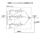
受信信号から他システムの干渉信号を除去する1つの手法は、最尤系列推定や線形等化を用いた逐次処理による干渉除去方法を使用する。しかしながら、この手法では、他システムのパラメータ(変調方式、トレーニングシンボル、シンボルレート等)に関する情報を自システムで事前に把握しておく必要がある。従って、他システムのパラメータが未知である場合には有効に対処することができない。受信信号から他システムの干渉信号を除去する別の手法は、分数間隔等化器(FSE:Fractionally Spaced Equalizer)及び周波数シフトフィルタ(FRESH:FREquency SHift filtering)を用いる。図6はFRESHの概略図を示す。図7はFESの概略図を示す。FSEやFRESHは、図1の適応フィルタとして使用することができる。図6に示されるように、FRESHは並列に接続された複数のFSEを含み、それらFSEの出力は合成される。合成後の出力はトレーニング信号から引かれ、誤差信号が生成される。この誤差信号が小さくなるように、FSEの各フィルタ係数が調整される。図7に示されるように、FSEは、そこに入力されるオーバーサンプルされた信号を遅延させる一連の遅延要素群を有し、各々の出力に係数又はウエイトciを乗算して合成する。この一群の係数はタップ係数とも呼ばれる(FRESH及びFSEについては、非特許文献1,2参照。)。
上記の従来技術では、図1の送信フィルタ1,受信フィルタ3の特性は、それらが対をなして整合フィルタを形成するようにシステム設計時に固定的に決定され、チャネル変動に対する補償のような動的な補償は専ら適応フィルタに委ねられている。従って、干渉状況によっては干渉除去能力が不足してしまうことが懸念される。特に、非所望信号のパラメータが未知であって、所望信号のキャリア周波数と非所望信号のキャリア周波数の間隔が接近すればするほど、干渉の抑圧が困難になる。
In the above-described prior art, the characteristics of the
本発明は、上記問題点の少なくとも1つに対処するためになされたものであり、その課題は、複数のシステムが同一の周波数帯域で通信を行う周波数共存環境において、他システムからの干渉信号のパラメータが既知でなくても自システムでの受信特性の劣化を軽減できる通信装置及び通信方法を提供することである。 The present invention has been made to address at least one of the above-described problems, and its problem is to solve the problem of interference signals from other systems in a frequency coexistence environment where a plurality of systems communicate in the same frequency band. To provide a communication apparatus and a communication method capable of reducing deterioration of reception characteristics in the own system even if parameters are not known.
一形態による通信装置は、
自システムが他システムと同一の周波数帯域で通信を行う周波数共存環境下において、伝達特性が変更可能なディジタルフィルタが使用される自システムの通信装置であって、
他システムからの干渉信号を検出する手段と、
検出結果に応じて、自システムからの送信信号の波形整形に使用される前記ディジタルフィルタの伝達特性を決定する手段と
を有し、自システムのキャリア周波数及び他システムのキャリア周波数の差が所定値より大きかった場合、前記決定する手段は、自システムのディジタルフィルタの通過帯域幅を狭くすることで、他システムからの干渉を自システムの送信側で回避し、
自システムのキャリア周波数及び他システムのキャリア周波数の差が所定値より小さかった場合、前記決定する手段は、受信側で受信した前記送信信号と、該受信した前記送信信号の中心周波数をナイキスト周波数の2倍だけシフトした信号とを重み付けして合成することで、他システムからの干渉を自システムの受信側で抑制する、通信装置である。
A communication device according to one aspect is
A communication device of the own system in which a digital filter whose transfer characteristics can be changed is used in a frequency coexistence environment in which the own system communicates in the same frequency band as another system,
Means for detecting interference signals from other systems;
Means for determining the transfer characteristic of the digital filter used for shaping the waveform of the transmission signal from the own system according to the detection result, and the difference between the carrier frequency of the own system and the carrier frequency of the other system is a predetermined value. If larger, the means for determining avoids interference from other systems on the transmission side of the own system by narrowing the pass bandwidth of the digital filter of the own system ,
When the difference between the carrier frequency of the own system and the carrier frequency of the other system is smaller than a predetermined value, the determining means determines the transmission signal received on the receiving side and the center frequency of the received transmission signal as the Nyquist frequency. in Rukoto be synthesized by weighting the by twice shifted signals, that suppressed Wins interference from other systems on the reception side of the local system, a communication device.
本発明によれば、複数のシステムが同一の周波数帯域で通信を行う周波数共存環境において、他システムからの干渉信号のパラメータが既知でなくても自システムでの受信特性の劣化を軽減できる。また,自システムが他システムに与える干渉を低減させることができる. According to the present invention, in a frequency coexistence environment in which a plurality of systems communicate in the same frequency band, it is possible to reduce degradation of reception characteristics in the own system even if parameters of interference signals from other systems are not known. In addition, it is possible to reduce the interference of the own system to other systems.
本発明の一形態によれば、干渉状況によって送受信フィルタが適応的に変更され、受信機の干渉除去能力が大きく維持される。所望信号と非所望信号の中心キャリア周波数の間隔が大きい場合は、フィルタの伝達特性の周波数方向の広がりを狭めるか,シンボルレートを下げることにより信号帯域を狭めることで干渉を抑制することができる。通信に使用されるフィルタは、ナイキスト周波数を境に奇対称の伝達特性を有する低域通過フィルタでもよい。フィルタは、ロールオフ率を変更することが可能なレイズドコサインフィルタでもよい。ロールオフ率をより小さくすることで、所望信号及び非所望信号を適切に分離することができる。 According to an aspect of the present invention, the transmission / reception filter is adaptively changed according to the interference state, and the interference cancellation capability of the receiver is largely maintained. When the distance between the center carrier frequencies of the desired signal and the undesired signal is large, interference can be suppressed by narrowing the signal band by narrowing the spread in the frequency direction of the transfer characteristics of the filter or by lowering the symbol rate. The filter used for communication may be a low-pass filter having an odd-symmetric transfer characteristic with respect to the Nyquist frequency. The filter may be a raised cosine filter capable of changing the roll-off rate. By making the roll-off rate smaller, the desired signal and the undesired signal can be appropriately separated.
一方、所望及び非所望信号の中心キャリア周波数の間隔が小さい場合は、フィルタのナイキスト周波数を超える周波数領域の伝達特性を、ロールオフフィルタ等のものよりも大きくすることで干渉信号を効果的に抑制できる。一例として、通信装置は伝達特性の中心周波数がそれぞれ異なる複数のフィルタと、複数のフィルタの出力及び既知信号に基づいて1以上のフィルタのフィルタ係数を適応的に調整する手段とを有する。複数のフィルタの伝達特性の中心周波数は、基準となるフィルタに対してナイキスト周波数の2倍(サイクリック周波数)だけ離れていてもよい。サイクリック周波数だけ位相のずれたフィルタの出力は互いに大きな相関を有する。その相関値が大きくなるように(既知信号との差分が小さくなるように)フィルタ係数を適応的に更新することで、干渉の抑圧された受信信号を得ることができる。中心キャリア周波数の間隔が大きくても小さくても、信号分離特性は良好に維持され、複数のシステムが同一の周波数帯域を共用する環境で周波数利用効率を向上させることができる。 On the other hand, when the distance between the center carrier frequencies of desired and undesired signals is small, interference signals can be effectively suppressed by making the transfer characteristics in the frequency region exceeding the Nyquist frequency of the filter larger than that of a roll-off filter. it can. As an example, the communication apparatus includes a plurality of filters having different center frequencies of transfer characteristics and means for adaptively adjusting filter coefficients of one or more filters based on outputs of the plurality of filters and known signals. The center frequency of the transfer characteristics of the plurality of filters may be separated from the reference filter by twice the Nyquist frequency (cyclic frequency). The outputs of the filters whose phases are shifted by the cyclic frequency have a large correlation with each other. By adaptively updating the filter coefficient so that the correlation value becomes large (so that the difference from the known signal becomes small), a reception signal in which interference is suppressed can be obtained. Regardless of whether the interval between the center carrier frequencies is large or small, the signal separation characteristics are maintained well, and the frequency utilization efficiency can be improved in an environment where a plurality of systems share the same frequency band.
複数のフィルタの1以上は、ナイキスト周波数を超える周波数領域でロールオフフィルタより大きな振幅特性を有してもよい。そのようなフィルタは例えばナイキスト周波数の2倍以上の帯域を通過させる低域フィルタであり、理想的には矩形フィルタとして表現される。 One or more of the plurality of filters may have a larger amplitude characteristic than the roll-off filter in a frequency region exceeding the Nyquist frequency. Such a filter is, for example, a low-pass filter that passes a band at least twice the Nyquist frequency, and is ideally expressed as a rectangular filter.
図8は、本発明の一実施例で使用される送信機のブロック図を示す。送信機は、送信信号生成部81、送信フィルタ82、D/A変換器83、ミキサ84、増幅器85、アンテナ86、干渉状況検出部87及び判断部88を有する。送信信号生成部81は図2(A)に示されるようなベースバンドの送信信号を生成する。送信フィルタ82は送信信号を帯域制限する。このフィルタの伝達特性は、制御情報に従って適切に設定される。D/A変換器83はベースバンドのディジタル信号をアナログ信号に変換する。ミキサ84は所望信号の搬送波(キャリア周波数f1)により周波数変換を行う。増幅器85は信号をアンテナ86から送信できるように信号の電力を増幅する。干渉状況検出部87は、他システムからの干渉信号(非所望信号)の周波数及び電力等の他システムのパラメータの内容を検出する。検出を行う方法については,受信信号を用いて干渉信号の状況を推定することにより検出が可能となる.また,送信機が有線ネットワーク等で干渉信号の送信機と接続されている場合は,干渉信号の送信機から制御信号を受信することにより検出を行うこともできる.判断部88は、検出された内容に基づいて、送信フィルタ82で使用すべきフィルタの伝達特性を決定する。本実施例では、同一の周波数帯域を共用する自システムと他システムとが互いに連絡し合うことで、大きな干渉が生じないようにシステム間で調整がなされる。なお、伝送される信号の帯域制限は、送信側の送信フィルタ及び受信側の受信フィルタが対になって行われる。従って、明示的には図示されていないが、送信フィルタ82に対応する受信フィルタが受信側に設けられており、帯域制限に関する処理が行われる。
FIG. 8 shows a block diagram of a transmitter used in one embodiment of the present invention. The transmitter includes a transmission
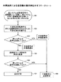
図9,10を参照しながら送信機の動作を説明する。図9は、そのような自他のシステム間の連絡により、送信フィルタの設定内容が決定される様子を模式的に示す。図10は本実施例による送信機の動作例を示すフローチャートである。 The operation of the transmitter will be described with reference to FIGS. FIG. 9 schematically shows how transmission filter setting contents are determined by such communication between the other system. FIG. 10 is a flowchart showing an operation example of the transmitter according to the present embodiment.
ステップ101では、信号の同時送信の可否について、他システムが自システムに問い合わせを行う。当然に、自システムから他システムに問い合わせが行われてもよい。便宜上、自システムは所望システムと言及され、他システムは干渉システムと言及される。この問い合わせは、システム間で伝送される何らかの制御チャネルを通じて行われてもよい。
In
ステップ102では、干渉状況検出部87で干渉状況が検出される。例えば、干渉状況検出部87は、自身の信号送信を停止し、一時的に他システムから信号の送信を行い,受信した他システムの信号の強度及び周波数等を測定する。
In step 102, the interference
ステップ103では、判断部88が、他システムが自システムと同じ時間に信号を送信してもよいか否かを判断する。例えば、受信した干渉システムの信号の強度が所定値より大きくない場合や、所望システムの信号の中心キャリア周波数と干渉システムの信号の中心キャリア周波数との差が所定値より大きい等の場合には、両システムから同時に信号が送信されても、システム間で大きな干渉は発生しないことが期待できる。この場合は、フローはステップ104に進み、所望システムは干渉システムに同時送信を許容する旨の通知を行う。
In
一方、受信した干渉システムの信号の強度が所定値より大きい場合や、所望システムの信号の中心キャリア周波数と干渉システムの信号の中心キャリア周波数との差が所定値より小さい等の場合には、両システムから同時に信号が送信されると、システム間で大きな干渉が発生するおそれがある。この場合は、フローはステップ105に進む。 On the other hand, if the received signal strength of the interference system is greater than the predetermined value, or if the difference between the center carrier frequency of the desired system signal and the center carrier frequency of the interference system signal is less than the predetermined value, both If signals are transmitted from the system at the same time, there is a risk of significant interference between the systems. In this case, the flow proceeds to step 105.
ステップ105では、信号の通信に使用するフィルタの伝達特性(フィルタ形状)が調整される、或いは適切な伝達特性を有するフィルタが選択される.具体的なフィルタ形状については後述される。
In
ステップ106では、ステップ105での調整後に、依然として信号の同時送信が許容できないか否かが判定される。それが許容されれば、フローはステップ104に進み、変更後のフィルタを用いた信号の通信が行われる。信号の同時送信が依然として許容されなかったならば、フローはステップ107に進む。
In
ステップ107では、判断部88は干渉システムに信号の同時送信は許容できない旨を通知する。この場合、干渉システムは同時に信号を送信することを断念する。この場合、干渉システムは別のタイムスロットで信号を送信してもよい。或いは、所望システムが信号の送信を断念してもよい。信号送信を断念するか否かの判定の際に、システム間の優先度が考慮されてもよい。
In
自他のシステムが同一の帯域で同時に信号を送信すると、互いに大きな干渉が生じてしまう場合には、フィルタ82の伝達特性が適切に調整される。伝送される信号の帯域制限は、送信側の送信フィルタ及び受信側の受信フィルタが対になって行われる。従って、明示的には図示されていないが、送信フィルタ82に対応する受信フィルタが受信側に設けられており、その受信フィルタの伝達特性も送信フィルタに合わせて調整されてもよい。
本発明の第2実施例では、伝達特性を調整する一例が説明される。以下の説明では、図10のステップ102で所望システムの信号の中心キャリア周波数と干渉システムの信号の中心キャリア周波数との差が測定され、その差が所定値より大きかったものとする。送信フィルタ82及び/又は受信フィルタは、ロールオフ率を変更することが可能なルートレイズドコサインフィルタであるとする。
If the other systems transmit signals simultaneously in the same band, if large interference occurs, the transfer characteristics of the
In the second embodiment of the present invention, an example of adjusting the transfer characteristic will be described. In the following description, it is assumed that the difference between the center carrier frequency of the signal of the desired system and the center carrier frequency of the signal of the interference system is measured at step 102 in FIG. 10, and the difference is larger than a predetermined value. It is assumed that the
図11は、フィルタを通過した後の所望信号のスペクトルと干渉信号のスペクトルを模式的に示す。所望システム及び干渉システムで通信に使用されるフィルタの調整前のロールオフ率は共に1.0であったとする。即ち、フィルタは、ナイキスト帯域の2倍の帯域に及ぶ伝達特性を有する。所望システムでの送信間隔はT1であり、所望システムのフィルタは2×1/(2T1)=1/T1の帯域幅に及ぶ。干渉システムでの送信間隔はT2であり、干渉システムのフィルタは2×1/(2T2)=1/T2の帯域幅に及ぶ。キャリア周波数間隔はΔfである。この場合、両システムから同時に信号が送信されると、図11(A)に示されるように、周波数軸上で部分的に重複した信号が受信される。このような状況が、図9の干渉状況検出部87及び判断部88、図10のステップ102,103で把握される。
FIG. 11 schematically shows the spectrum of the desired signal and the spectrum of the interference signal after passing through the filter. It is assumed that the roll-off rates before adjustment of the filters used for communication in the desired system and the interference system are both 1.0. That is, the filter has a transfer characteristic that covers a band twice as large as the Nyquist band. The transmission interval in the desired system is T 1 and the filter of the desired system spans a bandwidth of 2 × 1 / (2T 1 ) = 1 / T 1 . The transmission interval in the interference system is T 2 and the interference system filter covers a bandwidth of 2 × 1 / (2T 2 ) = 1 / T 2 . The carrier frequency interval is Δf. In this case, when signals are transmitted simultaneously from both systems, as shown in FIG. 11A, partially overlapping signals are received on the frequency axis. Such a situation is grasped by the interference
図12は、干渉量を推定する原理図を示す。スペクトルの形状は図11に示されるものと同じである。干渉量は、図12(A)中のスペクトルの重複部分近辺に示される破線の三角形(I)の面積の多少で評価される。三角形(I)の面積が所定値より大きければ、干渉が許容できないほど大きいものと考えられる。この場合、本実施例では、フィルタのロールオフ率が小さく変更され、図11,12の例ではロールオフ率が共に0.2に変更される。図11(B)は変更後のロールオフ率を有するフィルタを通過した信号のスペクトルを模式的に示す。この場合、通信に使用されるフィルタは、ナイキスト帯域の1.2倍の帯域に及ぶ伝達特性を有する。この場合の干渉量は、図12(B)の(I’)に示される三角形の面積で評価できる。フィルタのロールオフ率を変更することで、三角形の面積は(I)から(I’)に減少し、干渉量が低減されることが示される。 FIG. 12 shows a principle diagram for estimating the interference amount. The shape of the spectrum is the same as that shown in FIG. The amount of interference is evaluated based on the area of the dotted triangle (I) shown in the vicinity of the overlapping portion of the spectrum in FIG. If the area of the triangle (I) is larger than a predetermined value, it is considered that the interference is unacceptably large. In this case, in this embodiment, the roll-off rate of the filter is changed to be small, and in the examples of FIGS. 11 and 12, both roll-off rates are changed to 0.2. FIG. 11B schematically shows a spectrum of a signal that has passed through a filter having a roll-off rate after change. In this case, the filter used for communication has a transfer characteristic that covers a band that is 1.2 times the Nyquist band. The amount of interference in this case can be evaluated by the area of the triangle indicated by (I ′) in FIG. By changing the roll-off rate of the filter, the area of the triangle decreases from (I) to (I ′), indicating that the amount of interference is reduced.
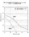
図13はフィルタのロールオフ率の変更前後における所望信号の平均ビットエラーレート(BER)のシミュレーション結果を示し,図14は干渉信号の平均ビットエラーレート(BER)のシミュレーション結果を示す。図13,14でのシミュレーションの条件は、図15に示される。何れの図も、平均Eb/N0が同じであっても、フィルタのロールオフ率を小さくすることで干渉を抑制でき、良好な平均ビットエラーレートが得られることを示す。 FIG. 13 shows the simulation result of the average bit error rate (BER) of the desired signal before and after the change of the filter roll-off rate, and FIG. 14 shows the simulation result of the average bit error rate (BER) of the interference signal. The simulation conditions in FIGS. 13 and 14 are shown in FIG. Each figure shows that even if the average E b / N 0 is the same, interference can be suppressed by reducing the roll-off rate of the filter, and a good average bit error rate can be obtained.
自他のシステムが同一の帯域で同時に信号を送信すると、互いに大きな干渉が生じてしまう場合には、フィルタ82の伝達特性が適切に調整される。帯域制限は、送信フィルタ及び受信フィルタが対になって行われる。その受信フィルタの伝達特性も送信フィルタに合わせて調整されてもよい。本発明の第3実施例では、特に送信フィルタおよび受信フィルタの伝達特性を調整するだけでは十分な干渉除去が実現できない場合に,図1の適応フィルタとして周波数シフトフィルタ用いて干渉除去を行う一例が説明される。以下の説明では、図10のステップ102で所望システムの信号の中心キャリア周波数と干渉システムの信号の中心キャリア周波数との差が測定され、その差が所定値より小さかったものとする。受信側において適応フィルタとして用いる周波数シフトフィルタを図16に示す.周波数シフトフィルタは、3系統に分岐した経路と、各経路からの信号を合成する合成部164と、合成部の出力信号及び所望信号(例えば、トレーニング信号)の差分を出力する誤差信号生成部165とを有する。分岐した経路1,2,3にはそれぞれ、FSEフィルタ161,162,163が設けられ、経路2,3には更に位相回転量を調整する位相調整部167,168が設けられている。FSEフィルタ161,162,163の各々は図7に示されるような構成及び機能を有する。経路2の位相調整部167は入力信号x(t)の中心周波数をナイキスト周波数の2倍(1/T1)だけプラス方向にシフトする。経路3の位相調整部168は入力信号x(t)の中心周波数をナイキスト周波数の2倍(1/T1)だけマイナス方向にシフトする。
If the other systems transmit signals simultaneously in the same band, if large interference occurs, the transfer characteristics of the
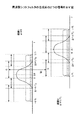
図17は、合成部164による合成前の経路1及び経路2での信号のスペクトルを示す。実線の波形は所望信号を示し、破線の波形は干渉信号を示す。本実施例では、キャリア周波数間隔Δfが所定値より小さいため、実施例2で説明された手法では干渉が十分に抑圧されない。経路2の位相調整部167は入力信号x(t)の中心周波数を(1/T1)だけシフトする。従って、経路2での信号のスペクトルは、図17下側に示されるように、周波数軸方向に1/T1だけずれたものになる。ディジタルフィルタの性質上、1/T1だけずれたこれらの信号は大きな相関を示す。1/T1はサイクリック周波数とも呼ばれる。従って、FSEフィルタ161,162からの信号は、干渉信号がなければ大きな信号に合成される。
FIG. 17 shows the spectrum of the signal in the
図18は、図17と同様であるが、経路1と経路3の信号のスペクトルを示す。経路3でのスペクトルは、図18下側に示されるように、経路2とのものは逆方向に1/T1だけずれたものになる。ディジタルフィルタの性質上、これらの信号も大きな相関を示す。従って、FSEフィルタ161,163からの信号も、干渉信号がなければ大きな信号に合成される。
FIG. 18 is similar to FIG. 17 but shows the spectrum of the signals of
合成部164からの出力信号は、誤差信号生成部165に入力される。誤差信号生成部165は、出力信号と所望信号(トレーニング信号)との差分を誤差信号として出力する。この誤差信号が小さくなるように、各FSEフィルタ161,162,163のフィルタ係数がそれぞれ適応的に更新され、以下同様な動作が反復される。合成部164からの出力信号が十分に大きな信号になるように各FSEフィルタの係数が調整できれば、干渉信号の影響が十分に抑制できている。
The output signal from the
本発明の第4実施例では、ルートレイズドコサインフィルタの代わりに、図19下側に示されるような矩形フィルタが使用される。図19に示される矩形フィルタは、ナイキスト帯域の2倍の帯域に及ぶ理想的な低域フィルタである。本実施例では、このような矩形フィルタが、送信フィルタに使用される。図20は、キャリア周波数間隔Δfがナイキスト周波数1/(2T1)より小さい場合の所望信号及び干渉信号を表す。図20(A)は、自他のシステムで共にルートレイズドコサインフィルタが使用された場合の信号のスペクトルを示し、図17(A)の波形と同一形状を示す。図20(B)は、自システムで矩形フィルタが使用され、他システムでルートレイズドコサインフィルタが使用された場合の信号のスペクトルを示し、図19の波形と同一形状を示す。図から明らかなように、矩形フィルタが使用される場合は、ナイキスト帯域(1/(2T1))を超える周波数領域でも比較的大きな振幅特性が示され、実施例3の場合よりも図16の経路1と経路2の相関及び経路1と経路3の相関が大きくなるため、より効果的に干渉を除去することができる。
In the fourth embodiment of the present invention, a rectangular filter as shown in the lower part of FIG. 19 is used instead of the root raised cosine filter. The rectangular filter shown in FIG. 19 is an ideal low-pass filter that covers a band twice the Nyquist band. In this embodiment, such a rectangular filter is used as a transmission filter. FIG. 20 shows a desired signal and an interference signal when the carrier frequency interval Δf is smaller than the
図21は矩形フィルタが使用された場合の経路1及び経路2の信号を示し、図22は経路1及び経路3の信号を示す。
FIG. 21 shows the signals of
なお、本実施例では、理想的な長方形フィルタが使用されたが、別のフィルタが使用されてもよい。例えば,ナイキスト周波数1/(2T1)を超える周波数領域で大きな振幅特性を示すフィルタが使用されてもよい。また、ナイキスト周波数1/(2T1)を超える周波数領域で大きな振幅特性を有し、シンボル間干渉が生じないフィルタが使用されてもよい。
In this embodiment, an ideal rectangular filter is used, but another filter may be used. For example, a filter showing a large amplitude characteristic in a frequency region exceeding the
図23は、送受信に使用するフィルタを様々に変化させた場合のビットエラーレートのシミュレーション結果を示す。シミュレーションで使用された諸条件は、干渉信号の中心キャリア周波数f2が所望信号の中心キャリア周波数f1と同一(Δf=0)であることを除いて図15に示されるものと同じである。図23は自システムの信号に対するシミュレーション結果を示す。図24は他システムの信号に対するシミュレーション結果を示す。各図では、
(1)所望信号がロールオフ率1.0のルートレイズドコサインフィルタを送信フィルタとして用い、干渉信号もロールオフ率1.0のルートレイズドコサインフィルタを送信フィルタとして用い,適応フィルタとしてFSEが使用された場合(FSE RRC/RRC),
(2)所望信号がロールオフ率1.0のルートレイズドコサインフィルタを送信フィルタとして用い、干渉信号もロールオフ率1.0のルートレイズドコサインフィルタを送信フィルタとして用い,適応フィルタとしてFRESHが使用された場合(FRESH RRC/RRC),
(3)所望信号がナイキスト帯域の2倍の帯域を有する矩形フィルタを送信フィルタとして用い、干渉信号がロールオフ率1.0のルートレイズドコサインフィルタを送信フィルタとして用い,適応フィルタとしてFSEが使用された場合(FSE Rect/RRC),
(4)所望信号がナイキスト帯域の2倍の帯域を有する矩形フィルタを送信フィルタとして用い、干渉信号がロールオフ率1.0のルートレイズドコサインフィルタを送信フィルタとして用い,適応フィルタとしてFRESHが使用された場合(FRESH Rect/RRC),
(5)所望信号がロールオフ率1.0のルートレイズドコサインフィルタを送信フィルタとして用い,干渉信号がナイキスト帯域の2倍の帯域を有する矩形フィルタを送信フィルタとして用い、適応フィルタとしてFSEが使用された場合(FSE RRC/Rect),
(6)所望信号がロールオフ率1.0のルートレイズドコサインフィルタを送信フィルタとして用い,干渉信号がナイキスト帯域の2倍の帯域を有する矩形フィルタを送信フィルタとして用い、適応フィルタとしてFRESHが使用された場合(FRESH RRC/Rect),
(7)所望信号及び干渉信号ともにナイキスト帯域の2倍の帯域を有する矩形フィルタを送信フィルタとして用い、適応フィルタとしてFSEが使用された場合(FSE Rect/Rect),
(8)所望信号及び干渉信号ともにナイキスト帯域の2倍の帯域を有する矩形フィルタを送信フィルタとして用い、適応フィルタとしてFRESHが使用された場合(FRESH Rect/Rect)
のシミュレーション結果が示されている。
FIG. 23 shows the simulation result of the bit error rate when the filter used for transmission / reception is variously changed. The conditions used in the simulation are the same as those shown in FIG. 15 except that the center carrier frequency f 2 of the interference signal is the same as the center carrier frequency f 1 of the desired signal (Δf = 0). FIG. 23 shows a simulation result for the signal of the own system. FIG. 24 shows simulation results for signals of other systems. In each figure,
(1) When a desired signal uses a root raised cosine filter with a roll-off factor of 1.0 as a transmission filter, an interference signal also uses a root raised cosine filter with a roll-off factor of 1.0 as a transmission filter, and FSE is used as an adaptive filter (FSE RRC / RRC),
(2) When a desired signal uses a root raised cosine filter with a roll-off factor of 1.0 as a transmission filter, an interference signal also uses a root raised cosine filter with a roll-off factor of 1.0 as a transmission filter, and FRESH is used as an adaptive filter (FRESH RRC / RRC),
(3) When a rectangular filter whose desired signal has twice the Nyquist band is used as a transmission filter, a root raised cosine filter with a roll-off factor of 1.0 is used as a transmission filter, and FSE is used as an adaptive filter (FSE Rect / RRC),
(4) When a rectangular filter whose desired signal has twice the Nyquist bandwidth is used as a transmission filter, a root raised cosine filter whose interference signal is a roll-off factor 1.0 is used as a transmission filter, and FRESH is used as an adaptive filter (FRESH Rect / RRC),
(5) When the desired signal uses a root raised cosine filter with a roll-off factor of 1.0 as the transmission filter, the interference signal uses a rectangular filter having a band twice the Nyquist band as the transmission filter, and FSE is used as the adaptive filter (FSE RRC / Rect),
(6) When a desired signal is a root raised cosine filter with a roll-off factor of 1.0 as a transmission filter, a rectangular filter having a band twice the Nyquist band as an interference signal is used as a transmission filter, and FRESH is used as an adaptive filter (FRESH RRC / Rect),
(7) When a rectangular filter having twice the Nyquist bandwidth is used as a transmission filter for both the desired signal and the interference signal, and FSE is used as an adaptive filter (FSE Rect / Rect),
(8) When both a desired signal and an interference signal use a rectangular filter that has twice the Nyquist bandwidth as a transmission filter and FRESH is used as an adaptive filter (FRESH Rect / Rect)
The simulation results are shown.
図23,24に示されているように、矩形フィルタを使用した方がより良好な平均ビットエラーレートを達成できることが分かる。 As shown in FIGS. 23 and 24, it can be seen that a better average bit error rate can be achieved by using the rectangular filter.
81 送信信号生成部
82 送信フィルタ
83 A/D変換器
84 ミキサ
85 増幅器
86 アンテナ
87 干渉状況検出部
88 判断部
161,162,163 FSEフィルタ
164 合成部
165 誤差信号生成部
167,168 位相調整部
DESCRIPTION OF
Claims (3)
他システムからの干渉信号を検出する手段と、
検出結果に応じて、自システムからの送信信号の波形整形に使用される前記ディジタルフィルタの伝達特性を決定する手段と
を有し、自システムのキャリア周波数及び他システムのキャリア周波数の差が所定値より大きかった場合、前記決定する手段は、自システムのディジタルフィルタの通過帯域幅を狭くすることで、他システムからの干渉を自システムの送信側で回避し、
自システムのキャリア周波数及び他システムのキャリア周波数の差が所定値より小さかった場合、前記決定する手段は、受信側で受信した前記送信信号と、該受信した前記送信信号の中心周波数をナイキスト周波数の2倍だけシフトした信号とを重み付けして合成することで、他システムからの干渉を自システムの受信側で抑制する、通信装置。 A communication device of the own system in which a digital filter whose transfer characteristics can be changed is used in a frequency coexistence environment in which the own system communicates in the same frequency band as another system,
Means for detecting interference signals from other systems;
Means for determining the transfer characteristic of the digital filter used for shaping the waveform of the transmission signal from the own system according to the detection result, and the difference between the carrier frequency of the own system and the carrier frequency of the other system is a predetermined value. If larger, the means for determining avoids interference from other systems on the transmission side of the own system by narrowing the pass bandwidth of the digital filter of the own system ,
When the difference between the carrier frequency of the own system and the carrier frequency of the other system is smaller than a predetermined value, the determining means determines the transmission signal received on the receiving side and the center frequency of the received transmission signal as the Nyquist frequency. in Rukoto be synthesized by weighting the by twice shifted signals, that suppressed Wins interference from other systems on the reception side of the local system, the communication device.
他システムからの干渉信号を検出するステップと、
検出結果に応じて、自システムからの送信信号の波形整形に使用される前記ディジタルフィルタの伝達特性を決定するステップと
を有し、自システムのキャリア周波数及び他システムのキャリア周波数の差が所定値より大きかった場合、前記決定するステップにおいて、自システムのディジタルフィルタの通過帯域幅を狭くすることで、他システムからの干渉を自システムの送信側で回避し、
自システムのキャリア周波数及び他システムのキャリア周波数の差が所定値より小さかった場合、前記決定するステップにおいて、受信側で受信した前記送信信号と、該受信した前記送信信号の中心周波数をナイキスト周波数の2倍だけシフトした信号とを重み付けして合成することで、他システムからの干渉を自システムの受信側で抑制する、通信方法。 A communication method in the own system in which a digital filter whose transfer characteristics can be changed is used in a frequency coexistence environment in which the own system communicates in the same frequency band as another system,
Detecting an interference signal from another system;
Determining a transfer characteristic of the digital filter used for shaping the waveform of the transmission signal from the own system according to the detection result, and the difference between the carrier frequency of the own system and the carrier frequency of the other system is a predetermined value. If it is larger, in the step of determining, by narrowing the pass bandwidth of the digital filter of the own system, interference from other systems is avoided on the transmission side of the own system ,
When the difference between the carrier frequency of the own system and the carrier frequency of the other system is smaller than a predetermined value, in the determining step, the transmission signal received on the receiving side and the center frequency of the received transmission signal are set to the Nyquist frequency. in Rukoto be synthesized by weighting the by twice shifted signals, that suppressed Wins interference from other systems on the reception side of the local system, a communication method.
Priority Applications (4)
| Application Number | Priority Date | Filing Date | Title |
|---|---|---|---|
| JP2005179894A JP4614829B2 (en) | 2005-06-20 | 2005-06-20 | Communication apparatus and communication method |
| EP06253187.6A EP1737134B1 (en) | 2005-06-20 | 2006-06-20 | Adaptive pulse shaping filter based on interference detection |
| US11/455,635 US7773948B2 (en) | 2005-06-20 | 2006-06-20 | Communication device and communication method |
| CN200610093081XA CN1885984B (en) | 2005-06-20 | 2006-06-20 | Communication device and method |
Applications Claiming Priority (1)
| Application Number | Priority Date | Filing Date | Title |
|---|---|---|---|
| JP2005179894A JP4614829B2 (en) | 2005-06-20 | 2005-06-20 | Communication apparatus and communication method |
Publications (2)
| Publication Number | Publication Date |
|---|---|
| JP2006352807A JP2006352807A (en) | 2006-12-28 |
| JP4614829B2 true JP4614829B2 (en) | 2011-01-19 |
Family
ID=37074731
Family Applications (1)
| Application Number | Title | Priority Date | Filing Date |
|---|---|---|---|
| JP2005179894A Expired - Fee Related JP4614829B2 (en) | 2005-06-20 | 2005-06-20 | Communication apparatus and communication method |
Country Status (4)
| Country | Link |
|---|---|
| US (1) | US7773948B2 (en) |
| EP (1) | EP1737134B1 (en) |
| JP (1) | JP4614829B2 (en) |
| CN (1) | CN1885984B (en) |
Families Citing this family (16)
| Publication number | Priority date | Publication date | Assignee | Title |
|---|---|---|---|---|
| KR100530365B1 (en) * | 2003-06-19 | 2005-11-22 | 삼성전자주식회사 | UWB wireless transmitter and receiver using UWB linear FM signals having opposite slopes and method thereof |
| CN101385252B (en) * | 2006-02-17 | 2012-12-05 | 日本电气株式会社 | Band limit method and radio communication system |
| WO2008126602A1 (en) * | 2007-03-16 | 2008-10-23 | Ntt Docomo, Inc. | Communication system, transmission device, reception device, and communication method |
| EP1976121A1 (en) * | 2007-03-31 | 2008-10-01 | Sony Deutschland Gmbh | Digital filter |
| US8204444B2 (en) * | 2009-02-04 | 2012-06-19 | Qualcomm Incorporated | Adjustable transmission filter responsive to internal sadio status |
| CN102123500B (en) * | 2010-01-08 | 2016-08-03 | 华为技术有限公司 | The resource allocation methods of multimode terminal and device |
| CN102281224B (en) * | 2010-06-08 | 2015-08-19 | 上海无线通信研究中心 | OFDM receiver and its implementation |
| CN102378190B (en) * | 2010-08-13 | 2015-08-12 | 中兴通讯股份有限公司 | Microcell WAP (wireless access point) and channel arrangement method, dynamic spectrum resource management system |
| US9413420B1 (en) | 2011-04-20 | 2016-08-09 | Hrl Laboratories, Llc | Adaptive interference removal for compressive signal detection and reconstruction in real time |
| US8837634B2 (en) * | 2012-10-05 | 2014-09-16 | Nokia Siemens Networks Oy | Methods and apparatus for signal filtering |
| US10305575B2 (en) * | 2013-01-08 | 2019-05-28 | Advanced Rf Technologies, Inc. | Mobile telecommunication repeater for canceling feedback signals |
| CN105207962B (en) * | 2015-06-28 | 2019-03-15 | 知鑫知识产权服务(上海)有限公司 | A kind of interference signal searching method of high freuqency accuracy |
| WO2017194167A1 (en) * | 2016-05-13 | 2017-11-16 | Huawei Technologies Co., Ltd. | Radio transceiving device and method using waveform adaptation |
| US10320481B2 (en) * | 2016-07-13 | 2019-06-11 | Space Systems/Loral, Llc | Flexible high throughput satellite system using optical gateways |
| EP3734921A1 (en) | 2019-04-30 | 2020-11-04 | Juniper Networks, Inc. | Methods and apparatus for optical communications via pulse amplitude modulation (pam) in dense wavelength-division multiplexing (dwdm) systems |
| CN111865410B (en) | 2019-04-30 | 2023-05-26 | 瞻博网络公司 | Method and apparatus for optical communication |
Citations (4)
| Publication number | Priority date | Publication date | Assignee | Title |
|---|---|---|---|---|
| JPH09270733A (en) * | 1996-03-29 | 1997-10-14 | Matsushita Electric Ind Co Ltd | Spread spectrum communication equipment |
| JPH11122311A (en) * | 1997-10-17 | 1999-04-30 | Fujitsu Ltd | Digital radio communication system and its adjustment method |
| JPH11154880A (en) * | 1997-09-05 | 1999-06-08 | Fujitsu Ltd | Method and device for correcting signal, distortion compensating device, distortion compensation data preparing device, and transmitter |
| WO2003015443A1 (en) * | 2001-08-01 | 2003-02-20 | Mitsubishi Denki Kabushiki Kaisha | Mobile communication system, mobile communication method, base station, and mobile station |
Family Cites Families (13)
| Publication number | Priority date | Publication date | Assignee | Title |
|---|---|---|---|---|
| FI98580C (en) * | 1991-11-14 | 1997-07-10 | Nokia Mobile Phones Ltd | Selective filtration in a cellular phone |
| US5519735A (en) * | 1994-04-28 | 1996-05-21 | Lockheed Missiles & Space Co., Inc. | Reconstructing a primary signal from many secondary signals |
| US20010055320A1 (en) * | 1994-12-15 | 2001-12-27 | Pierzga Wayne Francis | Multiplex communication |
| US6307868B1 (en) * | 1995-08-25 | 2001-10-23 | Terayon Communication Systems, Inc. | Apparatus and method for SCDMA digital data transmission using orthogonal codes and a head end modem with no tracking loops |
| CN1118949C (en) * | 1997-11-07 | 2003-08-20 | 皇家菲利浦电子有限公司 | Wireless communication device |
| US6445750B1 (en) * | 1998-04-22 | 2002-09-03 | Lucent Technologies Inc. | Technique for communicating digitally modulated signals over an amplitude-modulation frequency band |
| US6233594B1 (en) * | 1998-09-23 | 2001-05-15 | Globespan, Inc. | Decimation filter for oversampling analog-to digital converter |
| GB9823326D0 (en) * | 1998-10-26 | 1998-12-23 | Roke Manor Research | Adaptive filter structure |
| US6628728B1 (en) * | 1999-04-28 | 2003-09-30 | Cyntrust Communications, Inc. | Nyquist filter and method |
| SE517039C2 (en) * | 2000-05-31 | 2002-04-02 | Bjoern Ottersten | Device and method for channel interference suppression |
| EP1217798B1 (en) * | 2000-12-19 | 2007-11-07 | NTT DoCoMo, Inc. | Adaptive equalization method and adaptive equalizer |
| US7215715B2 (en) * | 2001-02-06 | 2007-05-08 | Maxim Integrated Products, Inc. | System and method of signal wave shaping for spectrum control of an OFDM signal |
| FI20012581A0 (en) * | 2001-12-27 | 2001-12-27 | Nokia Corp | Interference elimination method in communication system |
-
2005
- 2005-06-20 JP JP2005179894A patent/JP4614829B2/en not_active Expired - Fee Related
-
2006
- 2006-06-20 US US11/455,635 patent/US7773948B2/en not_active Expired - Fee Related
- 2006-06-20 CN CN200610093081XA patent/CN1885984B/en not_active Expired - Fee Related
- 2006-06-20 EP EP06253187.6A patent/EP1737134B1/en not_active Expired - Fee Related
Patent Citations (4)
| Publication number | Priority date | Publication date | Assignee | Title |
|---|---|---|---|---|
| JPH09270733A (en) * | 1996-03-29 | 1997-10-14 | Matsushita Electric Ind Co Ltd | Spread spectrum communication equipment |
| JPH11154880A (en) * | 1997-09-05 | 1999-06-08 | Fujitsu Ltd | Method and device for correcting signal, distortion compensating device, distortion compensation data preparing device, and transmitter |
| JPH11122311A (en) * | 1997-10-17 | 1999-04-30 | Fujitsu Ltd | Digital radio communication system and its adjustment method |
| WO2003015443A1 (en) * | 2001-08-01 | 2003-02-20 | Mitsubishi Denki Kabushiki Kaisha | Mobile communication system, mobile communication method, base station, and mobile station |
Also Published As
| Publication number | Publication date |
|---|---|
| JP2006352807A (en) | 2006-12-28 |
| EP1737134A2 (en) | 2006-12-27 |
| EP1737134B1 (en) | 2014-07-16 |
| US20060290819A1 (en) | 2006-12-28 |
| EP1737134A3 (en) | 2008-09-03 |
| CN1885984B (en) | 2010-05-12 |
| CN1885984A (en) | 2006-12-27 |
| US7773948B2 (en) | 2010-08-10 |
Similar Documents
| Publication | Publication Date | Title |
|---|---|---|
| JP4614829B2 (en) | Communication apparatus and communication method | |
| US7961806B2 (en) | Power adaptive channel estimation for a multi-path receiving | |
| US7636407B2 (en) | Signal detector used in wireless communication system | |
| JP4701964B2 (en) | Multi-user receiver | |
| JP4711819B2 (en) | Communication apparatus and communication method | |
| JP2008532354A (en) | Wireless communication apparatus and associated method for providing improved block equalization | |
| JP4654797B2 (en) | Equalizer and equalization method | |
| EP1002404B1 (en) | Truncated maximum likelihood sequence estimator for wireless local area networks | |
| MXPA05005844A (en) | Method and arrangement for filter bank based signal processing. | |
| EP2399353A1 (en) | Equaliser for an optical transmission system | |
| US7369631B1 (en) | Symbol synchronizer for software defined communications system signal combiner | |
| US7656940B2 (en) | Equalizer and equalizing method | |
| WO2006041054A1 (en) | Multicarrier communication apparatus and peak power suppressing method | |
| WO2017183631A1 (en) | Los-mimo demodulation device, communication device, los-mimo transmission system, los-mimo demodulation method and program | |
| KR20070110325A (en) | Method and system for channel equalization | |
| JP5114551B2 (en) | Method and apparatus for canceling partially known interference using transmit diversity based interference cancellation | |
| JP5361827B2 (en) | Transmitter and transmission method | |
| WO2019136526A1 (en) | Dual pulse shaping transmission system and method | |
| WO2007063855A1 (en) | Multicarrier transmitting apparatus, multicarrier receiving apparatus, transmitting method and receiving method | |
| WO2020209092A1 (en) | Wireless communication system, wireless communication method, transmission station device, and reception station device | |
| EP2025087B1 (en) | Timing errors | |
| JPH04360441A (en) | Interference compensation system | |
| JP5723240B2 (en) | Wireless communication system | |
| EP1718020B1 (en) | Measurement of equalizer span alignment with respect to channel condition | |
| Wilhelm | Whitened matched filter for attenuating frequency selectively faded interferers in GSM |
Legal Events
| Date | Code | Title | Description |
|---|---|---|---|
| A621 | Written request for application examination |
Free format text: JAPANESE INTERMEDIATE CODE: A621 Effective date: 20080306 |
|
| A977 | Report on retrieval |
Free format text: JAPANESE INTERMEDIATE CODE: A971007 Effective date: 20100427 |
|
| A131 | Notification of reasons for refusal |
Free format text: JAPANESE INTERMEDIATE CODE: A131 Effective date: 20100511 |
|
| A521 | Written amendment |
Free format text: JAPANESE INTERMEDIATE CODE: A523 Effective date: 20100712 |
|
| A131 | Notification of reasons for refusal |
Free format text: JAPANESE INTERMEDIATE CODE: A131 Effective date: 20100810 |
|
| A521 | Written amendment |
Free format text: JAPANESE INTERMEDIATE CODE: A523 Effective date: 20100930 |
|
| TRDD | Decision of grant or rejection written | ||
| A01 | Written decision to grant a patent or to grant a registration (utility model) |
Free format text: JAPANESE INTERMEDIATE CODE: A01 Effective date: 20101019 |
|
| A01 | Written decision to grant a patent or to grant a registration (utility model) |
Free format text: JAPANESE INTERMEDIATE CODE: A01 |
|
| A61 | First payment of annual fees (during grant procedure) |
Free format text: JAPANESE INTERMEDIATE CODE: A61 Effective date: 20101019 |
|
| R150 | Certificate of patent or registration of utility model |
Ref document number: 4614829 Country of ref document: JP Free format text: JAPANESE INTERMEDIATE CODE: R150 Free format text: JAPANESE INTERMEDIATE CODE: R150 |
|
| FPAY | Renewal fee payment (event date is renewal date of database) |
Free format text: PAYMENT UNTIL: 20131029 Year of fee payment: 3 |
|
| R250 | Receipt of annual fees |
Free format text: JAPANESE INTERMEDIATE CODE: R250 |
|
| R250 | Receipt of annual fees |
Free format text: JAPANESE INTERMEDIATE CODE: R250 |
|
| R250 | Receipt of annual fees |
Free format text: JAPANESE INTERMEDIATE CODE: R250 |
|
| R250 | Receipt of annual fees |
Free format text: JAPANESE INTERMEDIATE CODE: R250 |
|
| R250 | Receipt of annual fees |
Free format text: JAPANESE INTERMEDIATE CODE: R250 |
|
| R250 | Receipt of annual fees |
Free format text: JAPANESE INTERMEDIATE CODE: R250 |
|
| LAPS | Cancellation because of no payment of annual fees |