JP2007155195A - Cooling facility - Google Patents
Cooling facility Download PDFInfo
- Publication number
- JP2007155195A JP2007155195A JP2005350063A JP2005350063A JP2007155195A JP 2007155195 A JP2007155195 A JP 2007155195A JP 2005350063 A JP2005350063 A JP 2005350063A JP 2005350063 A JP2005350063 A JP 2005350063A JP 2007155195 A JP2007155195 A JP 2007155195A
- Authority
- JP
- Japan
- Prior art keywords
- cooling
- unit
- coil
- temperature control
- temperature
- Prior art date
- Legal status (The legal status is an assumption and is not a legal conclusion. Google has not performed a legal analysis and makes no representation as to the accuracy of the status listed.)
- Pending
Links
- 238000001816 cooling Methods 0.000 title claims abstract description 117
- 238000010438 heat treatment Methods 0.000 claims abstract description 7
- 238000009833 condensation Methods 0.000 claims description 8
- 230000005494 condensation Effects 0.000 claims description 8
- 238000010257 thawing Methods 0.000 claims description 8
- 238000001035 drying Methods 0.000 claims description 4
- 239000002918 waste heat Substances 0.000 abstract description 8
- 238000005265 energy consumption Methods 0.000 abstract description 5
- 210000002159 anterior chamber Anatomy 0.000 abstract description 3
- 239000002826 coolant Substances 0.000 abstract description 3
- 239000003507 refrigerant Substances 0.000 description 20
- 239000007788 liquid Substances 0.000 description 14
- 238000007791 dehumidification Methods 0.000 description 5
- 230000000694 effects Effects 0.000 description 5
- 238000010586 diagram Methods 0.000 description 3
- 239000003990 capacitor Substances 0.000 description 2
- 238000001704 evaporation Methods 0.000 description 2
- 230000008020 evaporation Effects 0.000 description 2
- 238000007710 freezing Methods 0.000 description 2
- 230000008014 freezing Effects 0.000 description 2
- 238000009434 installation Methods 0.000 description 2
- 238000005057 refrigeration Methods 0.000 description 2
- 230000009897 systematic effect Effects 0.000 description 2
- 238000003303 reheating Methods 0.000 description 1
Images
Landscapes
- Drying Of Gases (AREA)
Abstract
Description
本発明は、連続的に湿分が侵入してくる部屋(以後「前室」という)などを冷却する冷却設備に関し、例えば温度を5℃以下に制御する場合に好適な冷却設備の改良に関するものである。 The present invention relates to a cooling facility that cools a room (hereinafter referred to as “front chamber”) in which moisture continuously enters, for example, to an improvement of a cooling facility suitable for controlling the temperature to 5 ° C. or lower. It is.
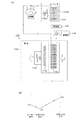
一般的な冷却設備としては、例えば図3(A)に示すものがある。同図において、冷却設備100は、圧縮機102,コンデンサ(凝縮器)104,受液器106,膨張弁108,冷却コイル(冷却器)110,ヒーター112,ファン(送風機)114を備えている。これらのうち、冷却器110,ヒーター112,ファン114は、冷蔵庫や冷凍庫の前室120に設置されており、他の装置は庫外に設置されている。
An example of a general cooling facility is shown in FIG. In the figure, a
次に、動作を説明すると、圧縮機102で圧縮されて高圧となった気体の冷媒(冷却媒体)は、コンデンサ104に送られ、ここで凝縮される。凝縮されて液体となった冷媒は、受液器106に収容され、更に膨張弁108に送られる。膨張弁108では、高圧の液体の冷媒の膨張が行われ、これによって得られた低温・低圧の冷媒が冷却コイル110に送られる。冷却コイル110には、ファン114によって前室120内の空気が送られており、空気の冷却・除湿が行われる。冷却・除湿後の空気は、ヒーター112に送られて加熱・乾燥が行われる。
Next, the operation will be described. The gaseous refrigerant (cooling medium) compressed to high pressure by the
例えば、図3(B)に示すように、3℃の空気は、冷却コイル110によって0℃に冷却・除湿され、更に、ヒーター112により1℃に加熱・乾燥されて、前室120に吹き出すという具合である。
For example, as shown in FIG. 3B, air at 3 ° C. is cooled and dehumidified to 0 ° C. by the
以上のように、従来の冷却設備では、1つの冷却ユニットより、前室内空気の冷却(例えば、+12〜+35℃),除湿,乾燥を行っている。このため、室内に再熱用の凝縮ユニットを設けるほか、室内温度が上昇してしまうため廃熱用に室外にも凝縮ユニットを設置しなければならない。従って、凝縮の再熱利用のコントロールが難しく、設備が複雑なものとなっているという不都合がある。一方、室外の凝縮ユニットにおける廃熱を、冷媒の加熱に利用できれば、システム全体として熱の利用効率が向上し、省エネルギーの冷却設備とすることができる。 As described above, in the conventional cooling facility, the cooling of the front room air (for example, +12 to + 35 ° C.), dehumidification, and drying is performed by one cooling unit. For this reason, in addition to providing a condensation unit for reheating in the room, the room temperature rises, so a condensation unit must be installed outside the room for waste heat. Therefore, there is an inconvenience that it is difficult to control the reheat utilization of the condensation, and the facilities are complicated. On the other hand, if the waste heat in the outdoor condensing unit can be used for heating the refrigerant, the heat utilization efficiency of the entire system can be improved and energy-saving cooling equipment can be obtained.
本発明は、以上の点に着目したもので、その目的は、冷媒凝縮時に発生する熱を再利用する際のコントロールを容易に行うことができる簡易な冷却設備を提供することである。他の目的は、熱の利用効率を高め、エネルギー消費を低減することである。 The present invention focuses on the above points, and an object of the present invention is to provide a simple cooling facility capable of easily performing control when reusing heat generated during refrigerant condensation. Another object is to increase heat utilization efficiency and reduce energy consumption.
前記目的を達成するため、本発明は、冷却ユニットによって冷却した空気を加熱・乾燥する冷却設備であって、前記冷却ユニットを、主冷却ユニット及び温度調節ユニットによって構成するとともに、前記主冷却ユニットの主冷却コイルと、前記温度調節ユニットの温度調節冷却コイル及び温度調節凝縮コイルとを、並べて配置し、前記主冷却コイル及び前記温度調節冷却コイルによって冷却された空気を、前記温度調節凝縮コイルによって加熱・乾燥することを特徴とする。 In order to achieve the above object, the present invention provides a cooling facility for heating and drying air cooled by a cooling unit, wherein the cooling unit includes a main cooling unit and a temperature adjustment unit, and the main cooling unit includes: The main cooling coil and the temperature adjusting cooling coil and the temperature adjusting condensing coil of the temperature adjusting unit are arranged side by side, and the air cooled by the main cooling coil and the temperature adjusting cooling coil is heated by the temperature adjusting condensing coil. -It is characterized by drying.
主要な形態の一つは、前記主冷却ユニットの冷却能力が、前記温度調節ユニットの冷却能力よりも大きいことを特徴とする。他の形態の一つは、デフロスト時は、前記主冷却ユニット及び温度調節ユニットのうち、デフロストの対象となるユニットの運転を停止することを特徴とする。更に他の形態は、前記温度調節凝縮コイルによる加熱後の空気の温度が、0℃以上であることを特徴とする。本発明の前記及び他の目的,特徴,利点は、以下の詳細な説明及び添付図面から明瞭になろう。 One of the main forms is characterized in that the cooling capacity of the main cooling unit is larger than the cooling capacity of the temperature control unit. One of the other forms is characterized in that during defrosting, the operation of the unit to be defrosted among the main cooling unit and the temperature control unit is stopped. Yet another embodiment is characterized in that the temperature of the air after being heated by the temperature adjusting condensing coil is 0 ° C. or higher. The above and other objects, features and advantages of the present invention will become apparent from the following detailed description and the accompanying drawings.
本発明によれば、主冷却ユニットと温度調節ユニットを用意し、温度調節ユニットの廃熱を利用して前室内空気の加熱・乾燥を行うこととしたので、簡便な設備で、冷媒凝縮時に発生する熱を再利用する際のコントロールを容易に行うことができる。また、熱の利用効率が向上し、エネルギー消費を低減することができる。 According to the present invention, the main cooling unit and the temperature control unit are prepared, and the front room air is heated and dried using the waste heat of the temperature control unit. It is possible to easily perform control when reusing heat. In addition, heat utilization efficiency can be improved and energy consumption can be reduced.
以下、本発明を実施するための最良の形態を、実施例に基づいて詳細に説明する。 Hereinafter, the best mode for carrying out the present invention will be described in detail based on examples.
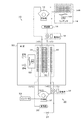
(1)装置の基本構成・・・図1には、本発明の実施例1の系統図が示されている。同図において、本実施例の冷却設備は、比較的冷却能力の高い主冷却ユニット10と、比較的冷却能力の低い温度調節ユニット30の2系統の冷却設備を備えている。これらのうち、主冷却ユニット10は、一般的な冷却設備とほぼ同様の構成となっており、圧縮機12,コンデンサ14,受液器16,膨張弁18,主冷却コイル20を備えている。コンデンサ14は、ファン14Aと主凝縮コイル14Bを含んでいる。主冷却コイル20は、冷蔵庫や冷凍庫の前室50内に設置されており、他の装置は庫外に設置されている。一方、温度調節ユニット30は、圧縮機32,温度調節凝縮コイル34,受液器36,バルブ37,膨張弁38,温度調節冷却コイル40を備えている。圧縮機32は、インバータ33を備えており、これによって圧縮機32の動作制御が可能となっている。温度調節ユニット30は、全体を前室50内に設置してもよいが、本実施例では、温度調節凝縮コイル34及び温度調節冷却コイル40は前室内に設置されており、他の装置は庫外に設置されている。
(1) Basic configuration of the apparatus FIG. 1 shows a system diagram of Embodiment 1 of the present invention. In the figure, the cooling equipment of this embodiment includes two systems of cooling equipment, that is, a
更に、本実施例では、前記主冷却ユニット10の主冷却コイル20,温度調節ユニット30の温度調節凝縮コイル34,及び温度調節冷却コイル40が、並べて配置されており、ファン52の作用によって、それらの各コイル20,34,40を前室50内の空気が通過するように構成されている。なお、ファン52は、冷却時は正転駆動され、デフロスト時は逆転駆動される。
Further, in the present embodiment, the
(2)主冷却ユニット10,温度調節ユニット30の個別動作・・・主冷却ユニット10のみの動作は、一般的な冷却設備の動作と同様である。すなわち、圧縮機12で圧縮されて高圧となった気体の冷媒は、コンデンサ14の主凝縮コイル14Bに送られる。主凝縮コイル14Bは、ファン14Aによる送風を受けており、冷媒の凝縮が行われる。凝縮されて液体となった冷媒は、受液器16に収容され、更に膨張弁18に送られる。膨張弁18では、高圧の液体冷媒の膨張が行われ、これによって得られた低温・低圧の冷媒が主冷却コイル20に送られる。主冷却コイル20を、ファン52の作用によって前室50内の空気が通過すると、その冷却・除湿が行われる。
(2) Individual operation of
次に、温度調節ユニット30の動作を説明する。圧縮機32で圧縮されて高圧となった気体の冷媒は、温度調節凝縮コイル34に送られる。温度調節凝縮コイル34は、ファン52による送風を受けており、冷媒の凝縮が行われる。凝縮されて液体となった冷媒は、受液器36に収容され、更にバルブ37を介して膨張弁38に送られる。膨張弁38では、高圧の液体冷媒の膨張が行われ、これによって得られた低温・低圧の冷媒が温度調節冷却コイル40に送られる。ファン52の作用によって前室50内の空気が温度調節冷却コイル40を通過すると、その冷却・除湿が行われる。このとき、インバータ33によって圧縮機32の動作を制御することで、前室温度を調整することができる。
Next, the operation of the
(3)主冷却ユニット10,温度調節ユニット30の全体動作・・・前室50内のコイル部分に着目すると、正転時、空気はまず温度調節冷却コイル40によって冷却・除湿され、次に主冷却コイル20によって更に冷却・除湿される。冷却後の空気は、温度調節凝縮コイル34に送られる。温度調節凝縮コイル34では、温度調節ユニット30の冷媒が凝縮されて液化するために発熱し、熱が冷媒から空気に伝達されるようになり、空気の加熱が行われる。すなわち、主冷却ユニット10及び温度調節ユニット30によって冷却された前室内空気は、温度調節ユニット30の廃熱を利用して加熱・乾燥される。
(3) Overall operation of the
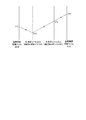
各部の温度の数値例を示すと、まず、前室内空気については、図2に示すように、温度調節冷却コイル40で3℃から2℃まで冷却・除湿され、次に、主冷却コイル20で2℃から0℃まで冷却・除湿される。その後、温度調節凝縮コイル34で1℃まで加熱・乾燥される。主冷却ユニット10,温度調節ユニット30における冷媒温度の一例は、図1中に示す。
As shown in FIG. 2, first, the indoor air is cooled and dehumidified from 3 ° C. to 2 ° C. by the temperature
(4)デフロスト(霜取り)時の動作・・・次に、デフロストを行うときの動作を説明する。上述した背景技術では、冷却コイル110による空気の冷却及びヒーター112による加熱を止めて、ファン114により空気を循環させることで、冷却コイル110のデフロストが行われる。すなわち、デフロスト時は、空気の除湿・乾燥が行われないので、前室の湿度が上昇する恐れがある。
(4) Operation at the time of defrosting (defrosting) ... Next, the operation at the time of defrosting will be described. In the background art described above, the cooling
これに対し、本実施例では、主冷却ユニット10の運転を停止するとともに、温度調節ユニット30を運転する。また、ファン52を逆転運転する。すると、前室内空気は、温度調節凝縮コイル34によって加熱・乾燥されるとともに、温度調節冷却コイル40によって冷却・除湿される。このため、上述した背景技術ほどに前室50の湿度が上昇せず、しかも、短時間で主冷却コイル20のデフロストを行うことができる。なお、温度調節冷却コイル40のデフロストを行うときは、主冷却ユニット10を運転するとともに、温度調節ユニット30の運転を停止すればよい。
On the other hand, in the present embodiment, the operation of the
(5)本実施例の効果・・・以上のように、本実施例によれば、次のような効果がある。
a,主冷却ユニットと温度調節ユニットを備え、温度調節ユニットの廃熱を利用して前室内空気の加熱・乾燥を行うこととしたので、簡便な設備で、冷媒凝縮時に発生する熱を再利用する際のコントロールを容易に行うことができる。
b,熱の利用効率が向上し、ヒーターを必要としないため、エネルギー消費を低減することができる。
c,冷却、除湿を行いつつデフロスト運転を行うことができる。
d,温度調節凝縮コイルの廃熱を有効利用し短時間でデフロストが可能となる。
e,既存の冷却設備にも追加設置することができる。
(5) Effects of the present embodiment As described above, the present embodiment has the following effects.
a. It has a main cooling unit and a temperature control unit, and uses the waste heat of the temperature control unit to heat and dry the front room air, so the heat generated during refrigerant condensation can be reused with simple equipment. Can be easily controlled.
b. The use efficiency of heat is improved and a heater is not required, so that energy consumption can be reduced.
c, Defrosting operation can be performed while cooling and dehumidifying.
d, Defrost can be achieved in a short time by effectively using the waste heat of the temperature-controlled condenser coil.
e. It can be additionally installed in existing cooling equipment.
なお、本発明は、上述した実施例に限定されるものではなく、本発明の要旨を逸脱しない範囲内において種々変更を加え得ることができる。例えば、以下のものも含まれる。
1),前記実施例は、連続的に湿分が侵入してくる部屋である冷蔵庫等の前室に本発明を適用したものであるが、冷蔵・冷凍設備一般,特に産業用の冷蔵・冷凍設備に対しても同様に適用可能である。しかし、前記前室のような温度が0℃以上の場合に、本発明は特に有効である。
2),各冷却ユニットの構成・配置も、上記実施例に限定されるものではない。例えば、前記実施例では、温度調節ユニット30の圧縮機32等を庫外に設置したが、前室内に設置することを妨げるものではなく、同様の作用を奏する適宜の設置箇所としてよい。
3),主冷却ユニット10と温度調節ユニット30の冷却能力の比率は適宜設定してよいが、例えば主冷却ユニット10が定格15kw,温度調節ユニット30が定格2.2kwという具合に設定する。
In addition, this invention is not limited to the Example mentioned above, A various change can be added in the range which does not deviate from the summary of this invention. For example, the following are also included.
1) In the above embodiment, the present invention is applied to the front room of a refrigerator or the like, which is a room where moisture enters continuously. In general, refrigeration and freezing equipment, particularly industrial refrigeration and freezing. The same applies to equipment. However, the present invention is particularly effective when the temperature in the anterior chamber is 0 ° C. or higher.
2) The configuration and arrangement of each cooling unit are not limited to the above embodiment. For example, in the above-described embodiment, the
3) The ratio of the cooling capacity of the
本発明を適用した冷却設備における省エネ効果の一例を示す。
a,従来の一般的な冷却設備
冷凍機:定格15kw,加熱ヒータ:定格9kw,
蒸発温度to:−5℃,庫内温度:+3℃,外気温度:+32℃,
冷却能力φo:41.0kw,加熱ヒータ:9kw,
従って、差し引き、32.0kwの冷却能力を有する。
運転上の消費電力 冷凍機:15.6kw,ヒータ:9kw,
従って、全体で、24.6kwの電力で運転している。
b,本発明を適用した冷却設備
主冷凍機:定格11kw,温度調節ユニット,定格2.2kw,
蒸発温度to:−5℃,庫内温度:+3℃,外気温度:+32℃,
冷却能力 主冷却コイルφo:35.0kw,温度調節冷却コイル:6.5kw,温度調節凝縮コイル:9.5kw,
従って、差し引き、32.0kwの冷却能力を有する。
運転上の消費電力 主冷却ユニット:13.1kw,温度調節ユニット:3.1kw,
従って、全体で、16.2kwの電力で運転している。
以上のa,bを比較すると、冷却能力は、いずれも32.0kwと同等であるに比べ、消費電力は従来設備が24.6kwであるのに対し、本発明設備では16.2kwであり、本発明設備を用いた場合、34%の省エネ効果が得られることが分かる。
An example of the energy-saving effect in the cooling equipment to which this invention is applied is shown.
a, Conventional general cooling equipment Refrigerator: Rated 15 kW, Heater: Rated 9 kW,
Evaporation temperature to: -5 ° C, inside temperature: + 3 ° C, outside air temperature: + 32 ° C,
Cooling capacity φo: 41.0 kW, heater: 9 kW,
Therefore, it has a cooling capacity of 32.0 kw by subtraction.
Power consumption during operation Refrigerator: 15.6 kW, heater: 9 kW,
Therefore, as a whole, it is operated with 24.6 kW of electric power.
b, Cooling equipment to which the present invention is applied Main refrigerator: Rated 11 kW, Temperature control unit, Rated 2.2 kW,
Evaporation temperature to: -5 ° C, inside temperature: + 3 ° C, outside air temperature: + 32 ° C,
Cooling capacity Main cooling coil φo: 35.0 kW, temperature control cooling coil: 6.5 kw, temperature control condensing coil: 9.5 kW,
Therefore, it has a cooling capacity of 32.0 kw by subtraction.
Power consumption during operation Main cooling unit: 13.1 kW, temperature control unit: 3.1 kW,
Therefore, as a whole, the operation is performed with the electric power of 16.2 kw.
Comparing the above a and b, the cooling capacity is equal to 32.0 kw, and the power consumption is 24.6 kw in the conventional facility, whereas the facility of the present invention is 16.2 kw. It can be seen that an energy saving effect of 34% can be obtained when the facility of the present invention is used.
本発明によれば、温度調節凝縮コイルの廃熱を利用して空気の加熱・乾燥が行われヒーターを別途必要としない。このため、エネルギー消費量が良好に低減されるので、特に、産業用の冷蔵倉庫やその前室などに好適である。 According to the present invention, air is heated and dried by using the waste heat of the temperature control condenser coil, and a heater is not required separately. For this reason, since energy consumption is reduced satisfactorily, it is particularly suitable for industrial refrigerated warehouses and front rooms thereof.
10:主冷却ユニット
12:圧縮機
14:コンデンサ
14A:ファン
14B:主凝縮コイル
16:受液器
18:膨張弁
20:主冷却コイル
30:温度調節ユニット
32:圧縮機
33:インバータ
34:温度調節凝縮コイル
36:受液器
37:バルブ
38:膨張弁
40:温度調節冷却コイル
50:前室
52:ファン
100:冷却設備
102:圧縮機
104:コンデンサ
104A:ファン
104B:凝縮コイル
106:受液器
108:膨張弁
110:冷却コイル
112:ヒーター
114:ファン
120:前室
10: main cooling unit 12: compressor 14: condenser 14A:
Claims (4)
前記冷却ユニットを、主冷却ユニット及び温度調節ユニットによって構成するとともに、
前記主冷却ユニットの主冷却コイルと、前記温度調節ユニットの温度調節冷却コイル及び温度調節凝縮コイルとを、並べて配置し、
前記主冷却コイル及び前記温度調節冷却コイルによって冷却された空気を、前記温度調節凝縮コイルによって加熱・乾燥することを特徴とする冷却設備。 A cooling facility for heating and drying the air cooled by the cooling unit,
The cooling unit is constituted by a main cooling unit and a temperature adjustment unit,
The main cooling coil of the main cooling unit, the temperature adjusting cooling coil and the temperature adjusting condensing coil of the temperature adjusting unit are arranged side by side,
A cooling facility characterized in that the air cooled by the main cooling coil and the temperature control cooling coil is heated and dried by the temperature control condensation coil.
The cooling equipment according to any one of claims 1 to 3, wherein the temperature of the air after heating by the temperature control condensing coil is 0 ° C or higher.
Priority Applications (1)
| Application Number | Priority Date | Filing Date | Title |
|---|---|---|---|
| JP2005350063A JP2007155195A (en) | 2005-12-02 | 2005-12-02 | Cooling facility |
Applications Claiming Priority (1)
| Application Number | Priority Date | Filing Date | Title |
|---|---|---|---|
| JP2005350063A JP2007155195A (en) | 2005-12-02 | 2005-12-02 | Cooling facility |
Publications (1)
| Publication Number | Publication Date |
|---|---|
| JP2007155195A true JP2007155195A (en) | 2007-06-21 |
Family
ID=38239808
Family Applications (1)
| Application Number | Title | Priority Date | Filing Date |
|---|---|---|---|
| JP2005350063A Pending JP2007155195A (en) | 2005-12-02 | 2005-12-02 | Cooling facility |
Country Status (1)
| Country | Link |
|---|---|
| JP (1) | JP2007155195A (en) |
Cited By (3)
| Publication number | Priority date | Publication date | Assignee | Title |
|---|---|---|---|---|
| KR100859126B1 (en) * | 2008-03-24 | 2008-09-18 | 주식회사 한국표준엔지니어링 | All-in-one and separate compromised air conditioning system |
| CN102539191A (en) * | 2012-01-06 | 2012-07-04 | 合肥通用机械研究院 | Air-cooling cold (hot) water unit experiment device with surface-cooling coil pipe regulation function |
| WO2016052211A1 (en) * | 2014-10-02 | 2016-04-07 | 三菱電機株式会社 | Dehumidifier |
Citations (3)
| Publication number | Priority date | Publication date | Assignee | Title |
|---|---|---|---|---|
| JPS5397734A (en) * | 1977-02-08 | 1978-08-26 | Daikin Ind Ltd | Air conditioner |
| JPS6021688A (en) * | 1983-07-15 | 1985-02-04 | Sanyo Electric Co Ltd | Beam index type color television receiver |
| JPS60108650A (en) * | 1983-11-15 | 1985-06-14 | 三菱電機株式会社 | air conditioner |
-
2005
- 2005-12-02 JP JP2005350063A patent/JP2007155195A/en active Pending
Patent Citations (3)
| Publication number | Priority date | Publication date | Assignee | Title |
|---|---|---|---|---|
| JPS5397734A (en) * | 1977-02-08 | 1978-08-26 | Daikin Ind Ltd | Air conditioner |
| JPS6021688A (en) * | 1983-07-15 | 1985-02-04 | Sanyo Electric Co Ltd | Beam index type color television receiver |
| JPS60108650A (en) * | 1983-11-15 | 1985-06-14 | 三菱電機株式会社 | air conditioner |
Cited By (4)
| Publication number | Priority date | Publication date | Assignee | Title |
|---|---|---|---|---|
| KR100859126B1 (en) * | 2008-03-24 | 2008-09-18 | 주식회사 한국표준엔지니어링 | All-in-one and separate compromised air conditioning system |
| CN102539191A (en) * | 2012-01-06 | 2012-07-04 | 合肥通用机械研究院 | Air-cooling cold (hot) water unit experiment device with surface-cooling coil pipe regulation function |
| WO2016052211A1 (en) * | 2014-10-02 | 2016-04-07 | 三菱電機株式会社 | Dehumidifier |
| JPWO2016052211A1 (en) * | 2014-10-02 | 2017-04-27 | 三菱電機株式会社 | Dehumidifier |
Similar Documents
| Publication | Publication Date | Title |
|---|---|---|
| US7743621B2 (en) | Multi-range composite-evaporator type cross-defrosting system | |
| KR101206278B1 (en) | Apparatus for Constant Temperature and Humidity System Using Heat Pump And Control Method Thereof | |
| US10495330B2 (en) | Air conditioning system | |
| US6694757B1 (en) | Multiple stage dehumidification and cooling system | |
| WO2019003306A1 (en) | Air conditioning device | |
| CN101713573B (en) | Dehumidifying air conditioning system | |
| JP2004020086A (en) | Dehumidification drying air conditioner | |
| CN106255858A (en) | Heat of mixing pumping unit | |
| KR101814074B1 (en) | Air-conditioning system using the outside air cold water | |
| KR20170138703A (en) | Air conditioner system and its control method | |
| JP2007155195A (en) | Cooling facility | |
| JP6490095B2 (en) | Air conditioning system | |
| CA2530567C (en) | Multi-range cross defrosting heat pump system | |
| JP2008232617A (en) | Air conditioner | |
| JP4187008B2 (en) | Air conditioner | |
| KR100441091B1 (en) | high effective cooling system of air conditioner | |
| JP6239100B2 (en) | Air conditioning system | |
| KR100796354B1 (en) | High Temperature Dryer Using Refrigerant Cycle System | |
| JP2022094105A (en) | Air conditioner | |
| KR100424542B1 (en) | freezing circuit saving power by re-heating construction | |
| KR20040037635A (en) | Method for power saving motion for dehumidification of air canditioner | |
| JPS5852924A (en) | Air conditioner utilizing condensing heat of coolant | |
| JP2002286309A (en) | Refrigerator | |
| KR100543606B1 (en) | How to change the operation mode of the dehumidifying air conditioner | |
| JPH04236062A (en) | Air conditioner |
Legal Events
| Date | Code | Title | Description |
|---|---|---|---|
| A621 | Written request for application examination |
Free format text: JAPANESE INTERMEDIATE CODE: A621 Effective date: 20081128 |
|
| A131 | Notification of reasons for refusal |
Free format text: JAPANESE INTERMEDIATE CODE: A131 Effective date: 20110412 |
|
| A02 | Decision of refusal |
Free format text: JAPANESE INTERMEDIATE CODE: A02 Effective date: 20111004 |