JP2007155142A - Air conditioner - Google Patents
Air conditioner Download PDFInfo
- Publication number
- JP2007155142A JP2007155142A JP2005346452A JP2005346452A JP2007155142A JP 2007155142 A JP2007155142 A JP 2007155142A JP 2005346452 A JP2005346452 A JP 2005346452A JP 2005346452 A JP2005346452 A JP 2005346452A JP 2007155142 A JP2007155142 A JP 2007155142A
- Authority
- JP
- Japan
- Prior art keywords
- air
- humidity control
- deodorizing
- control body
- supply
- Prior art date
- Legal status (The legal status is an assumption and is not a legal conclusion. Google has not performed a legal analysis and makes no representation as to the accuracy of the status listed.)
- Granted
Links
Images


Abstract
Description
本発明は、空調対象空間に供給する供給用空気の給気風路に通風作用する給気送風手段と、
空調対象空間外に排出する排出用空気の排気風路に通風作用する排気送風手段と、
一部を前記給気風路に位置させ且つ他の一部を前記排気風路に位置させるように配置される調湿体、及び、その調湿体における前記給気風路に位置させる部分及び前記排気風路に位置させる部分を回転に伴って変更させるように前記調湿体を駆動回転する調湿用駆動手段を備えた調湿手段と、
運転を制御する運転制御手段とが設けられた空調装置に関する。
The present invention provides an air supply / air blowing means that ventilates an air supply passage for supplying air to be supplied to an air-conditioning target space,
An exhaust air blowing means for ventilating the exhaust air path of the discharge air discharged outside the air-conditioning target space;
A humidity control body arranged so that a part is located in the air supply air passage and another part is located in the exhaust air air passage, and a portion of the humidity control body located in the air supply air passage and the exhaust Humidity control means comprising humidity control drive means for driving and rotating the humidity control body so as to change the part positioned in the air path with rotation;
The present invention relates to an air conditioner provided with operation control means for controlling operation.
かかる空調装置は、給気送風手段の通風作用により例えば外気を供給用空気として空調対象空間に供給すると共に、排気送風手段の通風作用により空調対象空間の空気を排出用空気として外部に排出するものであり、例えば、住宅内の複数の部屋等を空調対象空間とする用途で用いられる。 Such an air conditioner supplies, for example, outside air as supply air to the air-conditioning target space by the ventilation action of the air supply and blowing means, and discharges the air in the air-conditioning target space to the outside as the discharge air by the ventilation action of the exhaust ventilation means. For example, it is used in applications where a plurality of rooms in a house are air-conditioned spaces.
そして、一部を給気風路に位置させ且つ他の一部を排気風路に位置させるように配置した調湿体を調湿用駆動手段にて駆動回転させながら、その調湿体における給気風路に位置させる部分を供給用空気を通過させ且つその調湿体における排気風路に位置させる部分を排出用空気を通過させることにより、供給用空気を空調して空調対象空間に供給するようにして、空調対象空間を換気しながら空調するようになっている。 Then, while the humidity control body arranged so that a part is positioned in the air supply air path and the other part is positioned in the exhaust air path is driven and rotated by the humidity control driving means, the air supply air in the humidity control body The supply air is supplied to the air-conditioning target space by passing the supply air through the portion located in the passage and passing the discharge air through the portion located in the exhaust air passage of the humidity control body. Thus, the air-conditioned space is air-conditioned while being ventilated.
例えば、給気風路における調湿体よりも通風方向上手側箇所にて通流する空気に加熱作用するように、加湿用加熱手段を設けると、以下のように、供給用空気を無給水にて加湿して空調対象空間に供給することが可能となり、空調対象空間を換気しながら加湿することが可能となる。
つまり、加湿用加熱手段にて加熱された供給用空気が調湿体における給気風路に位置する部分を通過し、且つ、空調対象空間からの排出用空気が調湿体における排気風路に位置する部分を通過する形態で運転されることにより、空調対象空間からの排出用空気中の水蒸気が調湿体に吸収され、その調湿体に吸収された水分が供給用空気に放出されて供給用空気が加湿された状態で空調対象空間に供給されるので、空調対象空間を無給水にて加湿することができる(例えば、特許文献1参照。)。
For example, if heating means for humidification is provided so as to heat the air flowing in the upper side of the ventilation direction with respect to the humidity control body in the air supply air passage, supply air is supplied without water as follows: It becomes possible to humidify and supply the air-conditioning target space, and to humidify the air-conditioning target space while ventilating.
In other words, the supply air heated by the humidifying heating means passes through the portion of the humidity control body located in the air supply air path, and the exhaust air from the air conditioning target space is located in the exhaust air path of the humidity control body. By operating in a form that passes through the part to be air-conditioned, water vapor in the air for discharge from the air-conditioning target space is absorbed by the humidity control body, and the moisture absorbed by the humidity control body is released to the supply air and supplied Since the working air is supplied to the air-conditioning target space in a humidified state, the air-conditioning target space can be humidified with no water supply (see, for example, Patent Document 1).
ところで、例えば、住宅内の複数の部屋を空調対象空間とする場合においては、トイレ、浴室等、臭気が発生する可能性がある空間を含むものとなる等、空調対象空間からの排出用空気には、水溶性の臭い成分が含まれている可能性がある。 By the way, for example, in the case where a plurality of rooms in a house are air-conditioning target spaces, the exhaust air from the air-conditioning target spaces, such as toilets, bathrooms, etc., may include spaces where odors may occur. May contain water-soluble odor components.
しかしながら、従来の空調装置では、空調運転の実行中、水溶性の臭い成分を含んだ排出用空気が調湿体を通過するときに、その排出用空気に含まれる臭い成分が調湿体に付着したり、調湿体に吸収されている水分に溶解して、臭い成分が調湿体に蓄積すると共に、その調湿体に蓄積した臭い成分の一部が供給用空気に混入されて空調対象空間に戻ることになるので、臭い成分の蓄積量が多くなると、供給用空気に混入されて空調対象空間に戻る臭い成分が多くなって、空調対象空間を快適に空調することができなくなるという問題があった。 However, in the conventional air conditioner, during the air conditioning operation, when the discharge air containing the water-soluble odor component passes through the humidity control body, the odor component contained in the discharge air adheres to the humidity control body. Or dissolved in the moisture absorbed in the humidity control body, and the odor component accumulates in the humidity control body, and part of the odor component accumulated in the humidity control body is mixed into the supply air and is subject to air conditioning. As the amount of accumulated odorous components increases, the amount of odorous components mixed into the supply air and returning to the air-conditioned space increases, making it impossible to comfortably air-condition the air-conditioned space. was there.
本発明は、かかる実情に鑑みてなされたものであり、その目的は、臭いが発生する可能性がある空間を空調対象空間とする場合でも、空調対象空間に供給される供給用空気に臭い成分が混入されるのを抑制し得る空調装置を提供することにある。 The present invention has been made in view of such circumstances, and its purpose is to provide an odor component to supply air supplied to an air-conditioning target space even when a space where odors may occur is set as the air-conditioning target space. An object of the present invention is to provide an air conditioner that can suppress the mixing of air.
本発明の空調装置は、空調対象空間に供給する供給用空気の給気風路に通風作用する給気送風手段と、
空調対象空間外に排出する排出用空気の排気風路に通風作用する排気送風手段と、
一部を前記給気風路に位置させ且つ他の一部を前記排気風路に位置させるように配置される調湿体、及び、その調湿体における前記給気風路に位置させる部分及び前記排気風路に位置させる部分を回転に伴って変更させるように前記調湿体を駆動回転する調湿用駆動手段を備えた調湿手段と、
運転を制御する運転制御手段とが設けられたものであって、
第1特徴構成は、前記排気風路における前記調湿体よりも通風方向上手側箇所にて、通流する空気に対して加熱作用する除臭用加熱手段が設けられ、
前記運転制御手段は、
前記給気送風手段と前記排気送風手段とを作動させ、前記給気風路における前記調湿体よりも通風方向上手側箇所にて通流する空気に対して加熱作用する加湿用加熱手段を加熱作用状態にし、前記除臭用加熱手段を加熱停止状態にし及び前記調湿体を駆動回転するように前記調湿用駆動手段を作動させて、前記調湿手段にて供給用空気を加湿して空調対象空間に供給する、又は、前記給気送風手段と前記排気送風手段とを作動させ、前記除臭用加熱手段を加熱停止状態にし及び前記調湿体を駆動回転するように前記調湿用駆動手段を作動させて、前記調湿手段にて供給用空気を排出用空気と全熱交換させた状態で空調対象空間に供給する空調運転、及び、
前記給気送風手段と前記排気送風手段とのうちの少なくとも前記排気送風手段を作動させ、前記除臭用加熱手段を加熱作用状態にし及び前記調湿体を駆動回転するように前記調湿用駆動手段を作動させて、前記調湿体に吸収されている水分を排出用空気に放出させて除去する除臭運転を実行できるように構成され、且つ、
前記空調運転の開始指令に基づいて、前記除臭運転を実行した後に、前記空調運転を実行するように構成されている点を特徴とする。
The air conditioner of the present invention includes an air supply air blowing means that ventilates an air supply air passage for supply air supplied to the air conditioning target space,
An exhaust air blowing means for ventilating the exhaust air path of the discharge air discharged outside the air-conditioning target space;
A humidity control body arranged so that a part is located in the air supply air passage and another part is located in the exhaust air air passage, and a portion of the humidity control body located in the air supply air passage and the exhaust Humidity control means comprising humidity control drive means for driving and rotating the humidity control body so as to change the part positioned in the air path with rotation;
An operation control means for controlling the operation, and
The first characteristic configuration is provided with a deodorizing heating means that heats the flowing air at a location closer to the ventilation direction than the humidity control body in the exhaust air passage,
The operation control means includes
Actuating the air supply air blowing means and the air exhaust air blowing means to heat the humidifying heating means acting on the air flowing in the air flow direction upper side than the humidity control body in the air supply air passage The deodorizing heating means is in a heating stopped state, and the humidity control driving means is operated so as to drive and rotate the humidity control body, and the supply air is humidified and air-conditioned by the humidity control means. The humidity control drive so as to supply to the target space or to operate the supply air blowing means and the exhaust air blowing means so that the deodorizing heating means is in a heating stopped state and the humidity control body is driven to rotate. An air-conditioning operation in which the air is supplied to the air-conditioning target space in a state where the supply air is totally exchanged with the discharge air in the humidity control means, and
Driving the humidity control so as to activate at least the exhaust air blowing means of the supply air blowing means and the exhaust air blowing means, to bring the deodorizing heating means into a heating action state, and to drive and rotate the humidity control body A deodorizing operation in which the moisture is absorbed by the humidity control body is released into the discharge air and removed, and the deodorizing operation is performed.
Based on the start command of the air conditioning operation, the air conditioning operation is performed after the deodorizing operation is performed.
即ち、運転制御手段は、空調運転として、給気送風手段と排気送風手段とを作動させ、給気風路における調湿体よりも通風方向上手側箇所にて通流する空気に対して加熱作用する加湿用加熱手段を加熱作用状態にし、除臭用加熱手段を加熱停止状態にし及び調湿体を駆動回転するように調湿用駆動手段を作動させる運転(以下、加湿運転と記載する場合がある)、又は、給気送風手段と排気送風手段とを作動させ、除臭用加熱手段を加熱停止状態にし及び調湿体を駆動回転するように調湿用駆動手段を作動させる運転(以下、全熱交換運転と記載する場合がある)を実行し、除臭運転として、給気送風手段と排気送風手段とのうちの少なくとも前記排気送風手段を作動させ、除臭用加熱手段を加熱作用状態にし及び調湿体を駆動回転するように調湿用駆動手段を作動させて運転を実行し、そして、空調運転の開始指令が指令されると、除臭運転を実行した後に、空調運転を実行する。 That is, as the air conditioning operation, the operation control means operates the supply air blowing means and the exhaust air blowing means, and heats the air that flows at a location closer to the ventilation direction than the humidity control body in the supply air path. An operation for putting the humidifying heating means into a heating action state, putting the deodorizing heating means into a heating stopped state, and operating the humidity control driving means to drive and rotate the humidity control body (hereinafter sometimes referred to as a humidifying operation). ), Or an operation for operating the humidity control drive means to operate the supply air blowing means and the exhaust air blow means to turn the deodorizing heating means to the heating stopped state and to drive and rotate the humidity control body (hereinafter, all The deodorizing operation may be performed by operating at least the exhaust air blowing means of the supply air blowing means and the exhaust air blowing means to bring the deodorizing heating means into a heating action state. And to drive and rotate the humidity control body Running operation by operating the humidity drive means, and, when the start command of the air conditioning operation is commanded, after performing the deodorizing operation, it executes the air conditioning operation.
ちなみに、加湿運転では、空調対象空間からの排出用空気中の水蒸気が調湿体に吸収され、その調湿体に吸収されている水分が供給用空気に放出されて供給用空気が加湿される状態で、空調対象空間に供給される。
又、全熱交換運転では、駆動回転されている調湿体を供給用空気及び排出用空気が通過する形態で運転されて、調湿体において、供給用空気と排出用空気との間で顕熱交換されると共に潜熱交換されるので、供給用空気が排出用空気と全熱交換される状態で空調対象空間に供給される。
Incidentally, in the humidification operation, water vapor in the air for discharge from the air-conditioning target space is absorbed by the humidity control body, and moisture absorbed in the humidity control body is released to the supply air to humidify the supply air. In the state, it is supplied to the air-conditioning target space.
Further, in the total heat exchange operation, the humidity control body that is driven and rotated is operated in such a manner that the supply air and the discharge air pass through, and the humidity control body manifests between the supply air and the discharge air. Since the heat exchange and the latent heat exchange are performed, the supply air is supplied to the air-conditioning target space in a state where the heat is completely exchanged with the discharge air.
又、除臭運転では、空調対象空間からの排出用空気が除臭用加熱手段にて加熱された状態で調湿体における排気風路に位置する部分を通過する形態で運転されて、調湿体に吸収されている水分がその調湿体を通過する排出用空気に放出される状態となるので、調湿体に吸収されている水分に溶解している臭い成分は、水分と共に排出用空気に放出される状態で除去され、調湿体に付着している臭い成分は、排出用空気に放出されたり排出用空気中の水蒸気に溶解する状態で除去される。
ちなみに、除臭運転において、排気送風手段と共に給気送風手段を作動させると、調湿体を通過する供給用空気中の水蒸気がその調湿体に吸収され且つ調湿体に吸収されている水分がその調湿体を通過する排出用空気に放出される状態となるので、調湿体に付着している臭い成分を供給用空気から調湿体に吸収された水分に溶解させて、その水分を排出用空気に放出させることができものとなり、調湿体からの臭い成分の除去をより効果的に行わせることが可能となる。
Also, in the deodorizing operation, the exhaust air from the air-conditioning target space is operated in such a manner that it passes through the portion located in the exhaust air passage in the humidity control body while being heated by the deodorizing heating means. Since the moisture absorbed by the body is released to the exhaust air passing through the humidity control body, the odor component dissolved in the moisture absorbed by the humidity control body is discharged together with the moisture. The odorous component that is removed in a state where it is released and adhered to the humidity control body is removed in a state where it is released into the discharge air or dissolved in the water vapor in the discharge air.
Incidentally, in the deodorizing operation, when the supply air blowing means is operated together with the exhaust air blowing means, the water vapor in the supply air that passes through the humidity control body is absorbed by the humidity control body and is absorbed by the humidity control body. Is released into the exhaust air passing through the humidity control body, so that the odor component adhering to the humidity control body is dissolved in the moisture absorbed by the humidity control body from the supply air, and the water content is Can be discharged into the discharge air, and the odorous component from the humidity control body can be removed more effectively.
そして、空調運転の開始指令が指令されると、空調運転に先立って除臭運転が実行されるので、調湿体に臭い成分が付着していたり、調湿体に臭い成分が溶解した水分が吸収されていたとしても、その臭い成分が除臭運転にて調湿体から除去された後に、空調運転が実行されることとなり、空調対象空間に供給される供給用空気に臭い成分が混入されるのが抑制されるのである。
従って、臭いが発生する可能性がある空間を空調対象空間とする場合でも、空調対象空間に供給される供給用空気に臭い成分が混入されるのを抑制し得る空調装置を提供することができるようになった。
And when the start command of the air conditioning operation is commanded, the deodorizing operation is executed prior to the air conditioning operation, so that the odor component adheres to the humidity control body or the moisture in which the odor component dissolves in the humidity control body. Even if absorbed, after the odor component is removed from the humidity control body by the deodorizing operation, the air conditioning operation is executed, and the odor component is mixed in the supply air supplied to the air-conditioning target space. It is suppressed.
Therefore, even when the space where the odor may be generated is the air-conditioning target space, it is possible to provide an air-conditioning apparatus that can suppress the mixing of odorous components into the supply air supplied to the air-conditioning target space. It became so.
第2特徴構成は、
前記運転制御手段は、
前記給気送風手段と前記排気送風手段とを作動させ、前記給気風路における前記調湿体よりも通風方向上手側箇所にて通流する空気に対して加熱作用する加湿用加熱手段を加熱作用状態にし及び前記調湿体を駆動回転するように前記調湿用駆動手段を作動させて、前記調湿手段にて供給用空気を加湿して空調対象空間に供給する、又は、前記給気送風手段と前記排気送風手段とを作動させ及び前記調湿体を駆動回転するように前記調湿用駆動手段を作動させて、前記調湿手段にて供給用空気を排出用空気と全熱交換させた状態で空調対象空間に供給する空調運転、及び、
前記給気送風手段と前記排気送風手段とのうちの少なくとも前記排気送風手段を作動させた状態で、前記排気風路を通流する空気に含まれている臭い成分が前記調湿手段にて前記給気風路を通流する空気に放出される臭い戻りを抑制する臭い戻り抑制運転を実行できるように構成され、且つ、
前記空調運転の実行中に、空調対象空間内にて臭いが発生する又は臭いが発生する虞のある臭い戻り抑制必要状態になったと判別すると、前記空調運転を停止して、前記臭い戻り抑制運転を実行するように構成されている点を特徴とする。
The second feature configuration is
The operation control means includes
Actuating the air supply air blowing means and the air exhaust air blowing means to heat the humidifying heating means acting on the air flowing in the air flow direction upper side than the humidity control body in the air supply air passage The humidity control driving means is operated so that the humidity control body is driven and rotated, and the supply air is humidified and supplied to the air-conditioning target space by the humidity control means, or the supply air blow And the exhaust air blowing means are operated and the humidity control drive means is operated so as to drive and rotate the humidity control body so that the supply air and the exhaust air are totally exchanged by the humidity control means. Air conditioning operation to supply air conditioning target space
The odor component contained in the air flowing through the exhaust air passage in the state where at least the exhaust air blowing means of the supply air blowing means and the exhaust air blowing means is operated is It is configured to be able to perform an odor return suppression operation that suppresses odor return released to the air flowing through the air supply air passage, and
During the air conditioning operation, if it is determined that the odor is generated in the air-conditioning target space or the odor return suppression state that may cause the odor occurs, the air conditioning operation is stopped, and the odor return suppression operation is performed. It is characterized by being configured to execute.
即ち、運転制御手段は、空調運転として、先に第1特徴構成において説明したのと同様に加湿運転又は全熱交換運転を実行し、臭い抑制運転として、給気送風手段と排気送風手段とのうちの少なくとも排気送風手段を作動させた状態で、排気風路を通流する空気に含まれている臭い成分が調湿手段にて給気風路を通流する空気に放出される臭い戻りを抑制するように運転を実行し、そして、空調運転の実行中に、空調対象空間内にて臭いが発生する又は臭いが発生する虞のある臭い戻り抑制必要状態になったと判別すると、空調運転を停止して、臭い戻り抑制運転を実行する。 That is, the operation control means performs the humidification operation or the total heat exchange operation as described in the first feature configuration as the air conditioning operation, and performs the odor suppression operation between the supply air blowing means and the exhaust air blowing means. Smell components contained in the air flowing through the exhaust air passage are suppressed by the humidity control means to be released to the air flowing through the air supply air passage while at least the exhaust air blowing means is activated. The air conditioning operation is stopped when it is determined that an odor is generated in the air-conditioning target space or an odor return suppression state that may cause an odor has occurred during the air conditioning operation. Then, the odor return suppression operation is executed.
ちなみに、臭い戻り抑制運転では、給気送風手段と排気送風手段とのうちの少なくとも排気送風手段を作動させて、臭い成分を含んでいる虞がある空調対象空間の空気を排出するための空調対象空間の排気を継続しながら、排気風路を通流する空気に含まれている臭い成分が調湿手段にて給気風路を通流する空気に放出される臭い戻りを抑制するように運転される。 By the way, in the odor return suppression operation, the air-conditioning target for operating at least the exhaust air blowing means of the supply air blowing means and the exhaust air blowing means to discharge air in the air-conditioning target space that may contain odor components While continuing to exhaust the space, the odorous component contained in the air flowing through the exhaust air passage is operated to suppress the odor return released to the air flowing through the air supply air passage by the humidity control means. The
つまり、空調運転が行われているときに、例えば、トイレが使用されることに伴って、臭い戻り抑制必要状態になったと判別されると、空調運転が停止されると共に臭い戻り抑制運転が実行されて、空調対象空間の排気を継続しながら、排気風路を通流する空気に含まれている臭い成分が調湿手段にて給気風路を通流する空気に放出される臭い戻りが抑制されるので、空調対象空間に供給される供給用空気に臭い成分が混入されるのが抑制されるのである。
従って、臭いが発生する可能性がある空間を空調対象空間とする場合でも、空調対象空間に供給される供給用空気に臭い成分が混入されるのを抑制し得る空調装置を提供することができるようになった。
In other words, when the air conditioning operation is performed, for example, if it is determined that the odor return suppression is required due to the use of the toilet, the air conditioning operation is stopped and the odor return suppression operation is executed. As a result, the odor component contained in the air flowing through the exhaust air passage is suppressed by the humidity control means and the odor returning to the air flowing through the air supply air passage is suppressed while continuing to exhaust the air-conditioning target space. As a result, the mixing of odorous components into the supply air supplied to the air-conditioning target space is suppressed.
Therefore, even when the space where the odor may be generated is the air-conditioning target space, it is possible to provide an air-conditioning apparatus that can suppress the mixing of odorous components into the supply air supplied to the air-conditioning target space. It became so.
第3特徴構成は、上記第2特徴構成に加えて、
前記排気風路における前記調湿体よりも通風方向上手側箇所にて、通流する空気に対して加熱作用する除臭用加熱手段が設けられ、
前記運転制御手段は、前記空調運転では、前記除臭用加熱手段を加熱停止状態にするように構成され、
前記臭い戻り抑制運転が、前記給気送風手段と前記排気送風手段とのうちの少なくとも前記排気送風手段を作動させ、前記除臭用加熱手段を加熱作用状態にし及び前記調湿体を駆動回転するように前記調湿用駆動手段を作動させて、前記調湿体に吸収されている水分を排出用空気に放出させて除去する除臭運転である点を特徴とする。
The third feature configuration is in addition to the second feature configuration,
A deodorizing heating means is provided that heats the flowing air at a location closer to the ventilation direction than the humidity control body in the exhaust air passage,
The operation control means is configured to put the deodorizing heating means in a heating stopped state in the air conditioning operation,
The odor return suppression operation activates at least the exhaust air blowing means of the air supply air blowing means and the exhaust air blowing means, puts the deodorizing heating means into a heating action state, and drives and rotates the humidity control body. As described above, the deodorizing operation is characterized in that the humidity adjusting drive means is operated to release the moisture absorbed by the humidity adjusting body into the discharge air and remove it.
即ち、運転制御手段は、空調運転では、除臭用加熱手段を加熱停止状態にする。
そして、臭い戻り抑制運転として、給気送風手段と排気送風手段とのうちの少なくとも排気送風手段を作動させ、除臭用加熱手段を加熱作用状態にし及び調湿体を駆動回転するように調湿用駆動手段を作動させて、調湿体に吸収されている水分を排出用空気に放出させて除去する除臭運転が実行される。
That is, the operation control means puts the deodorizing heating means into the heating stopped state in the air conditioning operation.
Then, as the odor return suppression operation, humidity control is performed so that at least the exhaust air blowing means is operated among the supply air blowing means and the exhaust air blowing means, the deodorizing heating means is brought into a heating action state, and the humidity control body is driven to rotate. The deodorizing operation is performed in which the driving means is operated to release the moisture absorbed by the humidity control body to the discharge air and remove it.
つまり、空調運転では、除臭用加熱手段が加熱停止状態にされるので、空調運転として、先に第1特徴構成において説明したのと同様に加湿運転又は全熱交換運転が実行される。
そして、除臭運転では、空調対象空間からの排出用空気が除臭用加熱手段にて加熱された状態で調湿体における排気風路に位置する部分を通過する形態で運転されて、調湿体に吸収されている水分がその調湿体を通過する排出用空気に放出される状態となるので、排出用空気に臭い成分が含まれていたとしても、その臭い成分が調湿体に付着したり、調湿体に吸収されている水分に溶解するのを抑制することができるものとなり、排出用空気に含まれていた臭い成分が空調対象空間に供給されるのを抑制することができる。
ちなみに、除臭運転において、排気送風手段と共に給気送風手段を作動させると、調湿体を通過する供給用空気中の水蒸気がその調湿体に吸収され且つ調湿体に吸収されている水分がその調湿体を通過する排出用空気に放出される状態となって、調湿体から排出用空気に放出される水分量が多くなるので、排出用空気に臭い成分が含まれていたとしても、その臭い成分が調湿体に付着したり、調湿体に吸収されている水分に溶解するのをより一層抑制することができる。
That is, in the air conditioning operation, the deodorizing heating means is brought into a heating stop state, and therefore, as the air conditioning operation, the humidification operation or the total heat exchange operation is executed in the same manner as described in the first characteristic configuration.
In the deodorization operation, the exhaust air from the air-conditioning target space is operated in such a manner that it passes through a portion located in the exhaust air passage in the humidity control body while being heated by the deodorizing heating means. Since moisture absorbed by the body is released to the exhaust air passing through the humidity control body, even if the exhaust air contains odor components, the odor components adhere to the humidity control body Or dissolved in the moisture absorbed by the humidity control body, and the odorous component contained in the exhaust air can be suppressed from being supplied to the air-conditioning target space. .
Incidentally, in the deodorizing operation, when the supply air blowing means is operated together with the exhaust air blowing means, the water vapor in the supply air that passes through the humidity control body is absorbed by the humidity control body and is absorbed by the humidity control body. Since the amount of moisture released from the humidity control body to the discharge air increases, the odor component is contained in the discharge air. However, it is possible to further suppress the odor component from adhering to the humidity control body or dissolving in the moisture absorbed by the humidity control body.
要するに、空調対象空間に供給される供給用空気に臭い成分が混入されるのを抑制するのに好適な臭い戻り抑制運転を実行することができるようになった。 In short, the odor return suppressing operation suitable for suppressing the odorous component from being mixed into the supply air supplied to the air-conditioning target space can be executed.
第4特徴構成は、上記第2特徴構成に加えて、
前記排気風路における前記調湿体よりも通風方向上手側箇所にて、通流する空気に対して加熱作用する除臭用加熱手段が設けられ、
前記運転制御手段は、前記空調運転では、前記除臭用加熱手段を加熱停止状態にするように構成され、
前記臭い戻り抑制運転が、前記排気送風手段を作動させ、前記給気送風手段の作動と前記調湿体を駆動回転するための前記調湿用駆動手段の作動とのうちの少なくとも一方を停止する初期運転を、前記臭い戻り抑制必要状態が終了したと判別するまで又は前記臭い戻り抑制必要状態が終了したと判別した時点から終了遅延用の設定時間が経過するまで実行し、次に、前記給気送風手段と前記排気送風手段とのうちの少なくとも前記排気送風手段を作動させ、前記除臭用加熱手段を加熱作用状態にし、及び、前記調湿体を駆動回転するように前記調湿用駆動手段を作動させる又は前記調湿用駆動手段を停止させて、前記調湿体に吸収されている水分を排出用空気に放出させて除去する除臭運転を実行する運転である点を特徴とする。
In addition to the second feature configuration, the fourth feature configuration is
A deodorizing heating means is provided that heats the flowing air at a location closer to the ventilation direction than the humidity control body in the exhaust air passage,
The operation control means is configured to bring the deodorizing heating means into a heating stopped state in the air conditioning operation.
The odor return suppression operation activates the exhaust air blowing means and stops at least one of the operation of the air supply air blowing means and the operation of the humidity control driving means for driving and rotating the humidity control body. The initial operation is performed until it is determined that the odor return suppression necessary state has ended or until the end delay set time has elapsed from the time when it is determined that the odor return suppression necessary state has ended. Driving the humidity control so as to activate at least the exhaust air blowing means of the air blowing means and the exhaust air blowing means, bring the deodorizing heating means into a heating action state, and drive and rotate the humidity control body The dehumidifying operation is performed in which the dehumidifying operation is performed by operating the means or stopping the humidity control driving means to release the moisture absorbed by the humidity control body to the discharge air. .
即ち、運転制御手段は、空調運転では、除臭用加熱手段を加熱停止状態にする。
そして、臭い戻り抑制運転として、排気送風手段を作動させ、給気送風手段の作動と調湿体を駆動回転するための調湿用駆動手段の作動とのうちの少なくとも一方を停止する初期運転を、前記臭い戻り抑制必要状態が終了したと判別するまで又は前記臭い戻り抑制必要状態が終了したと判別した時点から終了遅延用の設定時間が経過するまで実行し、次に、給気送風手段と排気送風手段とのうちの少なくとも排気送風手段を作動させ、除臭用加熱手段を加熱作用状態にし、及び、調湿体を駆動回転するように調湿用駆動手段を作動させる又は調湿用駆動手段を停止させて、調湿体に吸収されている水分を排出用空気に放出させて除去する除臭運転を実行する運転が実行される。
That is, the operation control means puts the deodorizing heating means into the heating stopped state in the air conditioning operation.
Then, as the odor return suppression operation, the exhaust air blowing means is operated, and the initial operation for stopping at least one of the operation of the air supply air blowing means and the operation of the humidity control driving means for driving and rotating the humidity control body is performed. , Until it is determined that the odor return suppression necessary state has been completed or until it has been determined that the odor return suppression necessary state has ended, until the set time for termination delay has elapsed, Operate at least the exhaust air blowing means with the exhaust air blowing means, bring the deodorizing heating means into a heating action state, and operate the humidity adjusting drive means to drive and rotate the humidity control body or drive for humidity control The operation is executed to stop the means and perform the deodorizing operation in which the moisture absorbed in the humidity control body is released to the discharge air and removed.
つまり、空調運転では、除臭用加熱手段が加熱停止状態にされるので、空調運転として、先に第1特徴構成において説明したのと同様に加湿運転又は全熱交換運転が実行される。
そして、初期運転では、排出用空気が調湿体を通過することにより、排出用空気に含まれる臭い成分が調湿体に付着したり、調湿体に吸収されている水分に溶解したとしても、給気送風手段の作動が停止されて空調対象空間への供給用空気の供給が停止されている、又は、調湿用駆動手段が停止されて調湿体の駆動回転が停止されているので、排出用空気に含まれていた臭い成分が空調対象空間に戻るのを抑制することができる。
That is, in the air conditioning operation, the deodorizing heating means is brought into a heating stop state, and therefore, as the air conditioning operation, the humidification operation or the total heat exchange operation is executed in the same manner as described in the first characteristic configuration.
In the initial operation, even if the discharge air passes through the humidity control body, the odor component contained in the discharge air adheres to the humidity control body or dissolves in the moisture absorbed by the humidity control body. Since the operation of the air supply and blowing means is stopped and the supply of supply air to the air-conditioning target space is stopped, or the humidity control driving means is stopped and the driving rotation of the humidity control body is stopped. The odor component contained in the discharge air can be suppressed from returning to the air-conditioning target space.
ところで、空調対象空間において臭いが発生する状況が終了しても、空調対象空間には臭い成分が残留しており、又、空調対象空間の空気が空調装置に達するまでに時間がかかるので、臭い戻り抑制必要状態が終了したと判別しても、直ちに臭い成分が含まれた排出用空気が空調装置に供給されるのが停止するものではないため、初期運転を前記臭い戻り抑制必要状態が終了したと判別した時点から終了遅延用の設定時間が経過するまで実行するようにすることが好ましい。
又、初期運転において、除臭用加熱手段を加熱作用状態にすると、排出用空気が加熱された状態で調湿体における排気風路に位置する部分を通過するので、排出用空気に含まれる臭い成分が調湿体に付着し難く、又、調湿体に吸収されている水分に溶解し難くなるので好ましい。
By the way, even if the situation where odor occurs in the air-conditioning target space, odor components remain in the air-conditioning target space, and it takes time until the air in the air-conditioning target space reaches the air conditioner. Even if it is determined that the return suppression necessary state has ended, the supply of exhaust air containing odorous components does not immediately stop being supplied to the air conditioner. It is preferable that the process is executed until the end delay set time elapses from the time when it is determined that the process has been performed.
In the initial operation, when the deodorizing heating means is in a heating action state, the exhaust air passes through a portion located in the exhaust air passage in the humidity control body in a heated state, so that the odor contained in the exhaust air The component is preferable because it hardly adheres to the humidity control body and is difficult to dissolve in moisture absorbed by the humidity control body.
そして、その初期運転に続いて実行される除臭運転では、空調対象空間からの排出用空気が除臭用加熱手段にて加熱された状態で調湿体における排気風路に位置する部分を通過する形態で運転されて、調湿体に吸収されている水分がその調湿体を通過する排出用空気に放出される状態となるので、先の除臭運転において調湿体に吸収されている水分に溶解した臭い成分は、水分と共に排出用空気に放出される状態で除去され、先の除臭運転において調湿体に付着した臭い成分は、排出用空気中の水蒸気に溶解する状態で除去される。
尚、この除臭運転は、所定の設定時間の間実行され、そして、その除臭運転が前記設定時間の間実行されると、空調運転に復帰することになる。
And in the deodorizing operation performed following the initial operation, the air discharged from the air-conditioning target space passes through the portion located in the exhaust air passage in the humidity control body while being heated by the deodorizing heating means. Since the moisture absorbed in the humidity control body is released into the exhaust air passing through the humidity control body, it is absorbed by the humidity control body in the previous deodorizing operation. The odorous component dissolved in the moisture is removed in a state where it is released into the discharge air together with the moisture, and the odorous component adhering to the humidity control body in the previous deodorizing operation is removed in a state dissolved in the water vapor in the discharge air. Is done.
The deodorizing operation is executed for a predetermined set time, and when the deodorizing operation is executed for the set time, the operation returns to the air conditioning operation.
ちなみに、除臭運転において、排気送風手段と共に給気送風手段を作動させると、調湿体を通過する供給用空気中の水蒸気がその調湿体に吸収され且つ調湿体に吸収されている水分がその調湿体を通過する排出用空気に放出される状態となるので、調湿体に付着している臭い成分を供給用空気から調湿体に吸収された水分に溶解させて、その水分を排出用空気に放出させることができものとなり、調湿体からの臭い成分の除去をより効果的に行わせることが可能となる。
又、除臭運転において、調湿用駆動手段を作動させて調湿体を駆動回転すると、調湿体の全体にわたって臭い成分を除去することができるので好ましい。
但し、初期運転において、調湿用駆動手段を停止させて調湿体の駆動回転を停止する場合は、調湿体における排気風路に位置する部分のみについて、臭い成分を除去すれば十分であるので、除臭運転においては、調湿用駆動手段を停止させて調湿体の駆動回転を停止させると、調湿体からの臭い成分の除去を適切に行いながら、除臭運転の所要時間を短縮することができるので好ましい。
Incidentally, in the deodorizing operation, when the supply air blowing means is operated together with the exhaust air blowing means, the water vapor in the supply air that passes through the humidity control body is absorbed by the humidity control body and is absorbed by the humidity control body. Is released into the exhaust air passing through the humidity control body, so that the odor component adhering to the humidity control body is dissolved in the moisture absorbed by the humidity control body from the supply air, and the water content is Can be discharged into the discharge air, and the odorous component from the humidity control body can be removed more effectively.
Further, in the deodorizing operation, it is preferable to drive and rotate the humidity control body by operating the humidity control driving means because the odor component can be removed over the entire humidity control body.
However, in the initial operation, when the humidity control drive means is stopped to stop the driving rotation of the humidity control body, it is sufficient to remove the odor component only for the portion of the humidity control body located in the exhaust air passage. Therefore, in the deodorizing operation, if the humidity control driving means is stopped and the driving rotation of the humidity control body is stopped, the time required for the deodorizing operation is reduced while appropriately removing the odorous component from the humidity control body. This is preferable because it can be shortened.
要するに、空調対象空間に供給される供給用空気に臭い成分が混入されるのを抑制するのに好適な臭い戻り抑制運転を実行することができるようになった。 In short, the odor return suppressing operation suitable for suppressing the odorous component from being mixed into the supply air supplied to the air-conditioning target space can be executed.
第5特徴構成は、上記第2〜第4特徴構成のいずれかに加えて、
前記運転制御手段は、前記臭い戻り抑制必要状態になったと判別した時点から開始遅延用の設定時間経過後に、前記空調運転を停止して前記臭い戻り抑制運転を実行するように構成されている点を特徴とする。
In addition to any of the second to fourth feature configurations described above, the fifth feature configuration is
The operation control means is configured to stop the air-conditioning operation and execute the odor return suppression operation after a set time for start delay has elapsed since it is determined that the odor return suppression is required. It is characterized by.
即ち、運転制御手段は、臭い戻り抑制必要状態になったと判別した時点から開始遅延用の設定時間経過後に、空調運転を停止して臭い戻り抑制運転を実行する。 In other words, the operation control means stops the air-conditioning operation and executes the odor return suppression operation after the set time for the start delay has elapsed since it was determined that the odor return suppression is required.
つまり、臭い戻り抑制運転が実行されると、空調運転が停止されるので、空調対象空間の空調が停止されることになる。
又、臭い戻り抑制必要状態になったと判別しても、直ちに臭い成分が含まれた排出用空気が空調装置に達するものでない。
そこで、前記開始遅延用の設定時間として、例えば、臭い戻り抑制必要状態になったと判別した時点に空調対象空間に存在する空気が空調装置に達するのに要する時間に設定することにより、空調対象空間に臭いが戻るのを抑制しながら、臭い戻り抑制運転の実行時間を短くすることが可能となって、空調対象空間の空調が停止される時間を短くすることが可能となる。
又、臭い戻り抑制運転では、除臭用加熱手段が加熱作用状態になって消費エネルギが多くなるが、その臭い戻り抑制運転の実行時間を短くすることが可能となることにより、臭い戻り抑制運転を実行するための消費エネルギを低減することが可能となる。
従って、所望の空調が中断される時間の短縮及びランニングコストの低減を可能としながら、空調対象空間への臭い戻りを抑制することができるようになった。
That is, when the odor return suppression operation is executed, the air conditioning operation is stopped, so the air conditioning of the air conditioning target space is stopped.
Further, even if it is determined that the odor return suppression is necessary, the exhaust air containing the odor component does not immediately reach the air conditioner.
Therefore, by setting the set time for the start delay as, for example, the time required for the air present in the air-conditioning target space to reach the air-conditioning apparatus when it is determined that the odor return suppression state is required, the air-conditioning target space While suppressing the return of odor, it is possible to shorten the execution time of the odor return suppression operation and shorten the time during which the air conditioning of the air-conditioning target space is stopped.
Also, in the odor return suppression operation, the deodorizing heating means is in a heating action state and energy consumption increases, but the odor return suppression operation time can be shortened, thereby reducing the odor return suppression operation. It is possible to reduce the energy consumption for executing.
Therefore, it is possible to suppress the odor return to the air-conditioning target space while reducing the time during which the desired air conditioning is interrupted and reducing the running cost.
第6特徴構成は、上記第3特徴構成に加えて、
前記運転制御手段は、前記臭い戻り抑制必要状態が終了したと判別した時点から終了遅延用の設定時間が経過するまで、前記臭い戻り抑制運転を継続するように構成されている点を特徴とする。
In addition to the third feature configuration, the sixth feature configuration is
The operation control means is configured to continue the odor return suppression operation from the time when it is determined that the odor return suppression necessary state has ended until a set time for end delay elapses. .
即ち、運転制御手段は、臭い戻り抑制必要状態が終了したと判別した時点から終了遅延用の設定時間が経過するまで、臭い戻り抑制運転を継続する。 That is, the operation control means continues the odor return suppression operation from the time when it is determined that the odor return suppression necessary state has ended until the end delay setting time has elapsed.
つまり、空調対象空間において臭いが発生する状況が終了しても、空調対象空間には臭い成分が残留しており、又、空調対象空間の空気が空調装置に達するまでに時間がかかるので、臭い戻り抑制必要状態が終了したと判別しても、直ちに臭い成分が含まれた排出用空気が空調装置に供給されるのが停止するものではない。
そこで、前記終了遅延用の設定時間として、例えば、臭い戻り抑制必要状態が終了したと判別した時点から、臭い成分が含まれた排出用空気が空調装置に供給されなくなるのに要する時間に設定することにより、少なくとも、臭い成分が含まれた排出用空気が空調装置に供給されなくなるまで、臭い戻り抑制運転を実行させるようにすることが可能となる。
従って、空調対象空間への臭い戻りをより一層抑制することができるようになった。
In other words, even if the situation where odor occurs in the air-conditioning target space, odor components remain in the air-conditioning target space, and it takes time for the air in the air-conditioning target space to reach the air conditioner. Even if it is determined that the return suppression necessary state has ended, the supply of exhaust air containing odorous components to the air conditioner does not immediately stop.
Therefore, the set time for the end delay is set, for example, to a time required for the exhaust air containing the odor component to be no longer supplied to the air conditioner from the time when it is determined that the odor return suppression necessary state has ended. This makes it possible to execute the odor return suppressing operation until at least the discharge air containing the odor component is not supplied to the air conditioner.
Therefore, the smell return to the air-conditioning target space can be further suppressed.
〔第1実施形態〕
以下、本発明を住宅内を略全域にわたって換気する全体換気用の空調装置に適用した場合の第1実施形態を説明する。
図1及び図2に示すように、空調装置は、外気OAを空調対象空間としての複数の空調対象室に供給するための供給用空気SAとして装置内に吸い込む供給用空気入口1si、その供給用空気SAを送出する供給用空気出口1so、空調対象室の室内気RAを空調対象室外に排出するための排出用空気EAとして装置内に吸い込む排出用空気入口1ei及びその排出用空気EAを送出する排出用空気出口1eoを備えたケーシング1を用いて組み付けて構成してあり、図示は省略するが、住宅の天井裏等に配置する。
[First Embodiment]
Hereinafter, a first embodiment in a case where the present invention is applied to an air conditioner for general ventilation that ventilates the entire area of a house will be described.
As shown in FIGS. 1 and 2, the air conditioner includes a supply air inlet 1si for sucking into the apparatus as supply air SA for supplying outside air OA to a plurality of air-conditioning target rooms as air-conditioning target spaces. Supply air outlet 1so for sending air SA, discharge air inlet 1ei sucked into the apparatus as discharge air EA for discharging room air RA in the air-conditioning target room to the outside of the air-conditioning target room, and its discharge air EA are sent out The casing 1 having the discharge air outlet 1eo is assembled and configured, and although not shown, it is arranged on the ceiling of the house.
そして、図示は省略するが、外気を導入する外気導入ダクトを前記供給用空気入口1siに接続し、各空調対象室の給気口に接続した給気ダクトを前記供給用空気出口1soに接続し、各空調対象室の排気口に接続した排気ダクトを前記排出用空気入口1eiに接続し、排出用空気を屋外等に排出する排気ダクトを前記排出用空気出口1eoに接続する。
そして、前記外気導入ダクトを通じて導入した外気OAを空調して供給用空気SAとして前記給気ダクトを通じて各空調対象室に供給する共に、前記排気ダクトを通じて各空調対象室から吸込んだ室内気RAを排出用空気EAとして前記排気導出ダクトを通じて屋外に排出するように構成してある。
And although illustration is abbreviate | omitted, the external air introduction duct which introduces external air is connected to the said supply air inlet 1si, and the supply duct connected to the supply port of each air-conditioning object room is connected to the said supply air outlet 1so. The exhaust duct connected to the exhaust port of each air conditioning target room is connected to the exhaust air inlet 1ei, and the exhaust duct that exhausts the exhaust air to the outside is connected to the exhaust air outlet 1eo.
The outside air OA introduced through the outside air introduction duct is air-conditioned and supplied as supply air SA to each air conditioning target room through the air supply duct, and the indoor air RA sucked from each air conditioning target room is discharged through the exhaust duct. The air EA is discharged to the outside through the exhaust outlet duct.
この第1実施形態の空調装置は、図2に示すように、空調対象室に供給する供給用空気SAの給気風路2に通風作用する給気送風手段としての給気送風機3と、空調対象室外に排出する排出用空気EAの排気風路4に通風作用する排気送風手段としての排気送風機5と、一部を前記給気風路2に位置させ且つ他の一部を前記排気風路4に位置させるように配置される調湿体6及びその調湿体6における前記給気風路2に位置させる部分及び前記排気風路4に位置させる部分を回転に伴って変更させるように前記調湿体6を駆動回転する調湿用駆動手段としての調湿用電動モータ7を備えた調湿手段としての調湿部Lと、前記給気風路2における前記調湿体6よりも通風方向上手側箇所にて、通流する空気に対して加熱作用する加湿用加熱手段としての加湿用加熱器8と、前記排気風路4における前記調湿体6よりも通風方向上手側箇所にて、通流する空気に対して加熱作用する除臭用加熱手段としての除臭用加熱器20と、一部を前記給気風路2における前記加湿用加熱器8よりも通風方向上手側に位置させ且つ他の一部を前記排気風路4における前記調湿体6よりも通風方向下手側に位置させるように配置される顕熱交換体9及びその顕熱交換体9における前記給気風路2に位置させる部分及び前記排気風路4に位置させる部分を回転に伴って変更させるように前記顕熱交換体9を駆動回転する顕熱交換用電動モータ10を備えた顕熱交換部Sと、この空調装置の運転を制御する運転制御手段としての運転制御部11と、その運転制御部11に各種制御情報を指令する遠隔操作式の操作部12等を備えて構成してある。
As shown in FIG. 2, the air conditioner of the first embodiment includes an
そして、前記調湿部Lを、前記調湿体6の駆動回転速度を変更調節自在に構成し、前記加湿用加熱器8及び前記除臭用加熱器20を夫々、加熱作用状態と加熱停止状態とに切り換え自在に構成してある。
And the said humidity control part L is comprised so that change and adjustment of the drive rotational speed of the said
以下、空調装置の各部について説明を加える。
図1及び図2に示すように、前記ケーシング1は、直方体形状に形成し、そのケーシング1の一側面に、前記供給用空気出口1so及び前記排出用空気入口1eiを並べて設け、それら供給用空気出口1so及び排出用空気入口1eiを設けた側面に対向する側面に、前記供給用空気入口1si及び前記排出用空気出口1eoを供給用空気入口1siが前記供給用空気出口1soと同じ側に位置する状態で並べて設けてある。
Hereinafter, each part of the air conditioner will be described.
As shown in FIGS. 1 and 2, the casing 1 is formed in a rectangular parallelepiped shape, and the supply air outlet 1so and the discharge air inlet 1ei are arranged side by side on one side of the casing 1, and the supply air The supply air inlet 1si and the discharge air outlet 1eo are located on the same side as the supply air outlet 1so on the side surface opposite to the side surface provided with the outlet 1so and the discharge air inlet 1ei. They are arranged side by side.
図2及び図3に示すように、前記調湿部Lにおける調湿体6の支持構造及び回転駆動構造と、前記顕熱交換部Sにおける顕熱交換体9の支持構造及び回転駆動構造は、同様であるので、以下、前記調湿部Lを対象にして、調湿体6の支持構造及び回転駆動構造を説明する。
As shown in FIGS. 2 and 3, the support structure and the rotational drive structure of the
前記調湿体6は、所謂デシカントロータであり、円板形状でその軸心方向に通気自在なハニカム状の基材に吸湿材(シリカゲルや塩化リチウム等)を保持して構成し、前記調湿部Lは、前記調湿体6をその軸心にて回転自在に矩形枠状の支持枠13に支持すると共に、その支持枠13に、前記調湿用電動モータ7をその出力軸と前記調湿体6の外周部とにわたってベルト14を巻回した状態で設けて、ユニット状に構成してある。
The
前記支持枠13における前記調湿体6の軸心方向に並ぶ両側面部の夫々には、一対の概ね半円状の開口13wを、前記軸心方向視において一方の側面部の開口13wと他方の側面部の開口13wとが重なる状態で形成してある。
その支持枠13の各開口13wには、前記給気風路2と前記排気風路4とを分離するシール材15をその先端の開口縁が前記調湿体6に当接する状態で嵌め込んである。
A pair of substantially
A sealing
前記顕熱交換体9は、アルミニウム等の熱伝導率の高い材料にて、円板形状でその軸心方向に通気自在なハニカム状に形成し、前記顕熱交換部Sは、上述した調湿部Lと同様に、前記顕熱交換体9をその軸心にて回転自在に前記支持枠13に支持すると共に、その支持枠13に、前記顕熱交換用電動モータ10をその出力軸と前記顕熱交換体9の外周部とにわたってベルト14を巻回した状態で設けて、ユニット状に構成してある。
The
そして、図2に示すように、上述のようにユニット状に構成した調湿部L及び顕熱交換部Sを、調湿部Lが前記供給用空気出口1soの側に位置し且つ前記供給用空気入口1si及び前記供給用空気出口1soの並び方向に間隔を開けた状態で、調湿体6及び顕熱交換体9夫々の回転軸心が前記供給用空気入口1si及び前記供給用空気出口1soの並び方向に沿う姿勢にて、前記ケーシング1内に並べて設けてある。
Then, as shown in FIG. 2, the humidity control unit L and the sensible heat exchange unit S configured in a unit shape as described above are arranged so that the humidity control unit L is located on the supply air outlet 1so side and the supply unit. In a state where the air inlet 1si and the supply air outlet 1so are spaced apart from each other in the arrangement direction, the rotational axes of the
更に、そのケーシング1内を、仕切り壁16にて、前記供給用空気入口1si及び前記供給用空気出口1soが存在する側と前記排出用空気出口1eo及び前記排出用空気入口1eiが存在する側とに区画することにより、前記ケーシング1内に、一端が前記供給用空気入口1siに連通し且つ他端が前記供給用空気出口1soに連通する状態の前記給気風路2と、一端が前記排出用空気入口1eiに連通し且つ他端が前記排出用空気出口1eoに連通する状態の前記排気風路4を区画形成し、前記調湿体6を、その一部を前記給気風路2に位置させ且つ他の一部を前記排気風路4に位置させるように配置し、並びに、前記顕熱交換体9を、その一部を前記給気風路2に位置させ且つ他の一部を前記排気風路4に位置させるように配置してある。
Further, inside the casing 1, at the
そして、前記調湿用電動モータ7により前記調湿体6を駆動回転することにより、前記調湿体6における前記給気風路2に位置させる部分及び前記排気風路4に位置させる部分を回転に伴って変更させるように構成し、前記顕熱交換用電動モータ10により前記顕熱交換体9を駆動回転することにより、前記顕熱交換体9における前記給気風路2に位置させる部分及び前記排気風路4に位置させる部分を回転に伴って変更させるように構成してある。
そして、調湿用電動モータ7の回転速度を変更調節することにより、前記調湿体6の駆動回転速度を変更調節自在なように構成してある。
又、顕熱交換体9を駆動回転させるように顕熱交換用電動モータ10を作動させることにより、前記顕熱交換部Sにて供給用空気と排出用空気との間で顕熱交換させ、顕熱交換用電動モータ10を停止させることにより、前記顕熱交換部Sにおける供給用空気と排出用空気との間の顕熱交換を停止させるように構成してある。
Then, by driving and rotating the
And by changing and adjusting the rotation speed of the humidity control
Further, by operating the sensible heat exchange
前記加湿用加熱器8は、熱媒を通流させる熱媒流通管(図示省略)を空気の通過が可能なように蛇行状に配管した熱媒循環式に構成し、図2に示すように、その加湿用加熱器8を前記給気風路2における前記調湿部Lと前記顕熱交換部Sとの間に設けて、その加湿用加熱器8と熱源機(図示省略)とを熱媒循環路17にて接続して、その熱源機にて加熱した熱媒を熱媒循環路17を通じて加湿用加熱器8に循環供給するように構成してある。
そして、前記熱媒循環路17に加湿用熱動弁18を設けて、その加湿用熱動弁16を開閉して前記加湿用加熱器8への熱媒の供給を断続することにより、前記加湿用加熱器8を加熱作用状態と加熱停止状態とに切り換え自在に構成してある。
The
The
又、前記除臭用加熱器20は、前記加湿用加熱器8と同様に熱媒循環式に構成し、その除臭用加熱器20を排気風路4における前記調湿体6よりも通風方向上手側に設けて、その除臭用加熱器20と前記熱源機とを熱媒循環路21にて接続して、その熱源機にて加熱した熱媒を熱媒循環路21を通じて除臭用加熱器20に循環供給するように構成してある。
そして、前記熱媒循環路21に除臭用熱動弁22を設けて、その除臭用熱動弁22を開閉して前記除臭用加熱器20への熱媒の供給を断続することにより、前記加除臭用加熱器20を加熱作用状態と加熱停止状態とに切り換え自在に構成してある。
In addition, the deodorizing
Then, by providing a deodorizing
前記給気送風機3を、その吸い込み口を前記給気風路2内に臨ませ且つ吐き出し口を前記供給用空気出口1soに内嵌させた状態で前記給気風路2内に設けることにより、給気送風機3を、前記供給用空気入口1siから吸い込んだ供給用空気SAを、前記顕熱交換体9、前記加湿用加熱器8、前記調湿体6を順次通過させて前記供給用空気出口1soから送出するように、前記給気風路2に通風作用させる構成としてある。
又、前記排気送風機5を、その吸い込み口を前記排気風路4内に臨ませ且つ吐き出し口を前記排出用空気出口1eoに内嵌させた状態で前記排気風路4内に設けることにより、排気送風機5を、前記排出用空気入口1eiから吸い込んだ排出用空気EAを前記除臭用加熱器20、前記調湿体6、前記顕熱交換体9を順次通過させて前記排出用空気出口1eoから送出するように、前記排気風路4に通風作用させる構成としてある。
つまり、給気風路2の通風方向と排気風路4の通風方向が互いに逆向きになる。
By providing the
Further, the
That is, the ventilation direction of the
前記運転制御部11は、前記調湿部Lにて供給用空気を加湿して空調対象室に供給する前記空調運転としての加湿運転、前記調湿部Lにて供給用空気を排出用空気と全熱交換させた状態で空調対象室に供給する前記空調運転としての全熱交換運転、前記顕熱交換部Sにて供給用空気を排出用空気と顕熱交換させた状態で空調対象室に供給する顕熱交換運転、外気をそのまま供給用空気として空調対象室に供給し且つ空調対象室からの室内気をそのまま排出用空気として排出して空調対象室を換気する通常換気運転、供給用空気を前記加湿用加熱器8にて加熱して、そのまま空調対象室に供給する暖房運転、前記調湿体6に吸収されている水分を排出用空気に放出させて除去する除臭運転、及び、前記給気送風機3と前記排気送風機5とのうちの少なくとも排気送風機5を作動させた状態で、前記排気風路4を通流する空気に含まれている臭い成分が前記調湿部Lにて給気風路2を通流する空気に放出される臭い戻りを抑制する臭い戻り抑制運転を実行できるように構成してある。
The
以下、前記各運転における前記運転制御部11の制御動作について、説明を加える。
前記運転制御部11は、前記加湿運転では、給気送風機3と排気送風機5とを作動させ、加湿用加熱器8を加熱作用状態にし、除臭用加熱器20を加熱停止状態にし、調湿体6を調湿用設定速度で駆動回転するように調湿用電動モータ7を作動させ、及び、顕熱交換体9を顕熱交換用設定速度で駆動回転するように顕熱交換用電動モータ10を作動させるように構成してある。
Hereinafter, the control operation of the
In the humidification operation, the
前記運転制御部11は、前記全熱交換運転では、給気送風機3と排気送風機5とを作動させ、加湿用加熱器8と除臭用加熱器20とを加熱停止状態にし、調湿体6を前記調湿用設定速度よりも高速の全熱交換用設定速度で駆動回転するように調湿用電動モータ7を作動させ、及び、顕熱交換体9を顕熱交換用設定速度で駆動回転するように顕熱交換用電動モータ10を作動させるように構成してある。
In the total heat exchange operation, the
前記運転制御部11は、前記顕熱交換運転では、給気送風機3と排気送風機5とを作動させ、加湿用加熱器8と除臭用加熱器20とを加熱停止状態にし、調湿用電動モータ7を停止させ、及び、顕熱交換体9を顕熱交換用設定速度で駆動回転するように顕熱交換用電動モータ10を作動させるように構成してある。
In the sensible heat exchange operation, the
前記運転制御部11は、前記通常換気運転では、給気送風機3と排気送風機5とを作動させ、加湿用加熱器8と除臭用加熱器20とを加熱停止状態にし、及び、調湿用電動モータ7と顕熱交換用電動モータ10とを停止させるように構成してある。
前記運転制御部11は、前記暖房運転では、給気送風機3と排気送風機5とを作動させ、加湿用加熱器8を加熱作用状態にし、除臭用加熱器20を加熱停止状態にし、及び、調湿用電動モータ7と顕熱交換用電動モータ10とを停止させるように構成してある。
In the normal ventilation operation, the
In the heating operation, the
前記運転制御部11は、前記除臭運転では、給気送風機3と排気送風機5とを作動させ、前記加湿用加熱器8を加熱停止状態にし、前記除臭用加熱器20を加熱作用状態にし、調湿体6を駆動回転するように調湿用電動モータ7を作動させ、及び、顕熱交換用電動モータ10を停止させるように構成してある。
In the deodorizing operation, the
この第1実施形態では、前記運転制御部11は、前記臭い戻り抑制運転として、給気送風機3と排気送風機5とを作動させ、加湿用加熱器8を加熱停止状態にし、除臭用加熱器20を加熱作用状態にし、調湿体6を駆動回転するように調湿用電動モータ7を作動させ、及び、顕熱交換用電動モータ10を停止させる前記除臭運転を実行するように構成してある。
In the first embodiment, the
前記調湿用設定速度及び前記全熱交換用設定速度は、夫々予め設定して前記運転制御部11に記憶させてある。
以下、前記調湿用設定速度及び前記全熱交換用設定速度夫々の設定の仕方について説明を加える。
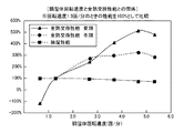
尚、前記調湿用設定速度については、詳細は後述の第7実施形態にて説明するが、調湿体6は、回転速度が1.3回/分のときに、調湿部Lの除湿性能が最大となるので、前記調湿用設定速度は、例えば1.3回/分に設定してある。
The humidity control setting speed and the total heat exchange setting speed are set in advance and stored in the
Hereinafter, description will be added on how to set the humidity control setting speed and the total heat exchange setting speed.
The humidity control setting speed will be described in detail in a seventh embodiment to be described later. However, the
図4中の実線は、空調対象室が冷房される夏期を想定して、調湿部Lの全熱交換性能を検証したものであり、前記加湿用加熱器8及び前記除臭用加熱器20を加熱停止状態にし、且つ、前記給気風路2の方が高温多湿になる状態でその給気風路2及び前記排気風路4の夫々に通風させる状態で、調湿体6の回転速度を変更させて、各回転速度での調湿部Lの全熱交換性能をエンタルピーにて、回転速度が1.3回/分のときを100%として比較したものである。
又、図4中の破線は、空調対象室が暖房される冬期を想定して、調湿部Lの全熱交換性能を検証したものであり、前記加湿用加熱器8及び前記除臭用加熱器20を加熱停止状態にし、且つ、前記排気風路4の方が高温多湿になる状態で前記給気風路2及び前記排気風路4の夫々に通風させる状態で、調湿体6の回転速度を変更させて、各回転速度での調湿部Lの全熱交換性能をエンタルピーにて、回転速度が1.3回/分のときを100%として比較したものである。
The solid line in FIG. 4 is the result of verifying the total heat exchange performance of the humidity control section L in the summer when the air-conditioning target room is cooled, and the
Moreover, the broken line in FIG. 4 has verified the total heat exchange performance of the humidity control part L in the winter when the air-conditioning target room is heated, and the
つまり、空調対象室が暖房される冬期等、排出用空気EAの方が供給用空気SAよりも高温多湿の状態となるときは、調湿部Lの全熱交換性能は、調湿体6の回転速度を前記調湿用設定速度である1.3回/分よりも高速にすると高くなり、2.8〜5.3回/分の範囲でより高くなり、4.7回/分のときに最高になることが分かる。
又、空調対象室が冷房される夏期等、供給用空気SAの方が排出用空気EAよりも高温多湿の状態となるときは、調湿部Lの全熱交換性能は、調湿体6の回転速度を前記調湿用設定速度である1.3回/分よりも高速にすると高くなり、4.0〜5.3回/分の範囲でより高くなり、4.7回/分のときに最高になることが分かる。
That is, when the air-conditioning target room is heated, such as in winter, when the exhaust air EA is hotter and humid than the supply air SA, the total heat exchange performance of the humidity control section L is that of the
Further, when the supply air SA is in a higher temperature and humidity state than the discharge air EA, such as in summer when the air-conditioning target room is cooled, the total heat exchange performance of the humidity control section L is that of the
調湿体6の回転速度を高くすることにより全熱交換性能を向上することができることについて考察すると、調湿体6の駆動回転速度を高くすることにより、調湿体6が給気風路2や排気風路4を移動する速度が速くなるので、調湿体6と供給用空気や排出用空気との間で顕熱及び潜熱の交換を十分に行わせながら、調湿体6における、供給用空気や排出用空気との間で顕熱及び潜熱の交換が行われた部分を速く移動させることが可能となり、調湿体6での供給用空気や排出用空気との間の全熱交換量を多くすることができるのである。
Considering that the total heat exchange performance can be improved by increasing the rotational speed of the
従って、空調対象室が暖房される冬期等、排出用空気EAの方が供給用空気SAよりも高温多湿の状態のときは、前記全熱交換用設定速度を、前記調湿用設定速度の2.2〜4.1倍に設定するのが好ましく、前記調湿用設定速度の3.6倍に設定するのが最も好ましい。
又、空調対象室が冷房される夏期等、供給用空気SAの方が排出用空気EAよりも高温多湿の状態のときは、前記全熱交換用設定速度を、前記調湿用設定速度の3.1〜4.1倍に設定するのが好ましく、前記調湿用設定速度の3.6倍に設定するのが最も好ましい。
Therefore, when the air-conditioning target room is heated, such as in the winter, when the exhaust air EA is hotter and humid than the supply air SA, the total heat exchange setting speed is set to 2 of the humidity adjustment setting speed. It is preferably set to 2 to 4.1 times, and most preferably set to 3.6 times the set speed for humidity control.
When the supply air SA is hotter and humid than the exhaust air EA, such as in summer when the air-conditioning target room is cooled, the total heat exchange setting speed is set to 3% of the humidity adjustment setting speed. It is preferable to set it to .1 to 4.1 times, and it is most preferable to set it to 3.6 times the set speed for humidity control.
以上のように、調湿体6の回転速度を調湿用設定速度よりも高くすることにより、調湿部Lの全熱交換性能を向上可能なことが分かる。
As mentioned above, it turns out that the total heat exchange performance of the humidity control part L can be improved by making the rotational speed of the
前記操作部12には、図示を省略するが、上述のようにこの空調装置にて実行可能な複数種の運転のうち、除臭用運転及び臭い戻り抑制運転以外の運転を択一的に指令する運転切換部、及び、空調装置の停止を指令する停止スイッチを設けてある。
Although not shown in the figure, the
又、住宅の複数の空調対象室のうちの一つであるトイレ内に人が存在するか否かを検出する人存否検出センサ19を設けてある。ちなみに、この実施形態では、前記人存否検出センサ19はその検出域に人が存在するとオン信号を出力し、検出域に人が存在しないとオフ信号を出力するように構成してある。
そして、前記運転制御部11は、前記人存否検出センサ19からの信号がオンのときは、トイレ内にて臭いが発生する虞がある臭い戻り抑制必要状態であると判別し、前記人存否検出センサ19からの信号がオフのときは、臭い戻り抑制必要状態ではないと判別するように構成してある。
In addition, a human presence /
Then, when the signal from the presence /
次に、前記操作部12の運転切換部からの指令情報に基づく前記運転制御部11の制御動作について、説明する。
前記運転制御部11は、前記操作部12の運転切換部から、前記顕熱交換運転、前記通常換気運転及び前記暖房運転のうちのいずれか一つが指令されると、指令された運転を実行するように構成してある。
又、運転制御部11は、操作部12の運転切換部から前記加湿運転が指令されると、前記除臭運転を除臭用設定時間の間実行した後、前記加湿運転を実行し、且つ、その加湿運転の実行中に、人存否検出センサ19の検出情報に基づいて臭い戻り抑制必要状態になったと判別すると、前記加湿運転を停止して、前記臭い戻り抑制運転を実行するように構成してある。
ちなみに、前記除臭用設定時間は、例えば、前記調湿体6が1回転するのに要する時間以上に設定する。
Next, the control operation of the
When one of the sensible heat exchange operation, the normal ventilation operation, and the heating operation is commanded from the operation switching unit of the
In addition, when the humidification operation is commanded from the operation switching unit of the
Incidentally, the set time for deodorization is set, for example, longer than the time required for the
又、運転制御部11は、操作部12の運転切換部から前記全熱交換運転が指令されると、前記除臭運転を除臭用設定時間の間実行した後、前記全熱交換運転を実行し、且つ、その全熱交換運転の実行中に、人存否検出センサ19の検出情報に基づいて臭い戻り抑制必要状態になったと判別すると、前記全熱交換運転を停止して、前記臭い戻り抑制運転を実行するように構成してある。
In addition, when the total heat exchange operation is commanded from the operation switching unit of the
又、運転制御部11は、操作部12の停止スイッチから運転停止が指令されると、給気送風機3と排気送風機5とを停止させ、加湿用加熱器8が加熱作用状態のときは加熱停止状態に切り換え、除臭用加熱器20が加熱作用状態のときは加熱停止状態に切り換え、調湿体6を駆動回転しているときは調湿用電動モータ7を停止させ、及び、顕熱交換体9を駆動回転しているときは顕熱交換用電動モータ10を停止させる停止処理を実行して、空調装置を停止させる。
When the
次に、図5に基づいて、前記操作部12の運転切換部から前記加湿運転又は前記全熱交換運転が指令されたときの前記運転制御部11の制御動作、及び、前記加湿運転又は前記全熱交換運転の実行中に前記臭い戻り抑制必要状態になったと判別したときの前記運転制御部11の制御動作について、説明を加える。
Next, based on FIG. 5, the control operation of the
運転制御部11は、操作部12の運転切換部から前記加湿運転が指令されたときは、人存否検出センサ19の検出情報に拘らず、前記除臭用設定時間が経過するまでの間は、給気送風機3と排気送風機5とを作動させ、加湿用加熱器8を加熱停止状態にし、除臭用加熱器20を加熱作用状態にし、調湿体6を調湿用設定速度で駆動回転するように調湿用電動モータ7を作動させ、及び、顕熱交換用電動モータ10を停止させる状態に維持して、除臭運転を実行し、前記除臭用設定時間が経過すると、加湿用加熱器8を加熱作用状態に切り換え、除臭用加熱器20を加熱停止状態に切り換え、顕熱交換体9を顕熱交換用設定速度で駆動回転するように顕熱交換用電動モータ10を作動させることにより、前記除臭運転を終了して、前記加湿運転を開始する。
When the humidification operation is instructed from the operation switching unit of the
そして、運転制御部11は、前記加湿運転の実行中に、人存否検出センサ19からの信号がオフからオンに変化することに基づいて、臭い戻り抑制必要状態になったと判別すると、加湿用加熱器8を加熱停止状態に切り換え、除臭用加熱器20を加熱作用状態に切り換え、顕熱交換用電動モータ10を停止させることにより、前記加湿運転を停止して、前記除臭運転を実行し、その除臭運転を人存否検出センサ19からの信号がオンの間継続する。
続いて、人存否検出センサ19からの信号がオンからオフに変化することに基づいて、臭い戻り抑制必要状態が終了したと判別すると、加湿用加熱器8を加熱作用状態に切り換え、除臭用加熱器20を加熱停止状態に切り換え、顕熱交換体9を顕熱交換用設定速度で駆動回転するように顕熱交換用電動モータ10を作動させることにより、前記除臭運転を停止して、前記加湿運転を再び実行する。
And if the
Subsequently, when it is determined that the odor return suppression necessary state has ended based on the signal from the presence /
運転制御部11は、操作部12の運転切換部から前記全熱交換運転が指令されたときは、人存否検出センサ19の検出情報に拘らず、前記除臭用設定時間が経過するまでの間は、給気送風機3と排気送風機5とを作動させ、加湿用加熱器8を加熱停止状態にし、除臭用加熱器20を加熱作用状態にし、調湿体6を調湿用設定速度で駆動回転するように調湿用電動モータ7を作動させ、及び、顕熱交換用電動モータ10を停止させる状態に維持して、前記除臭運転を実行し、前記除臭用設定時間が経過すると、除臭用加熱器20を加熱停止状態に切り換え、調湿体6を全熱交換用設定速度で駆動回転するように調湿用電動モータ7を作動させ、顕熱交換体9を顕熱交換用設定速度で駆動回転するように顕熱交換用電動モータ10を作動させることにより、前記除臭運転を終了して、前記全熱交換運転を開始する。
When the total heat exchange operation is instructed from the operation switching unit of the
そして、運転制御部11は、前記全熱交換運転の実行中に、人存否検出センサ19からの信号がオフからオンに変化することに基づいて、臭い戻り抑制必要状態になったと判別すると、除臭用加熱器20を加熱作用状態に切り換え、調湿体6を調湿用設定速度で駆動回転するように調湿用電動モータ7を作動させ、顕熱交換用電動モータ10を停止させることにより、前記全熱交換運転を停止して、前記除臭運転を実行し、その除臭運転を人存否検出センサ19からの信号がオンの間継続する。
続いて、人存否検出センサ19からの信号がオンからオフに変化することに基づいて、臭い戻り抑制必要状態が終了したと判別すると、除臭用加熱器20を加熱停止状態に切り換え、調湿体6を全熱交換用設定速度で駆動回転するように調湿用電動モータ7を作動させ、顕熱交換体9を顕熱交換用設定速度で駆動回転するように顕熱交換用電動モータ10を作動させることにより、前記除臭運転を停止して、前記全熱交換運転を再び実行する。
When the
Subsequently, based on the signal from the presence /
次に、上記の各運転による作用について、説明を加える。
前記加湿運転では、図2を参照すると、排出用空気入口1eiから排気風路4に吸い込まれた各空調対象室からの室内気RAは排出用空気EAとして、加熱停止状態の除臭用加熱器20、調湿用設定速度にて回転する調湿体6、顕熱交換用設定速度にて回転する顕熱交換体9を順次通過して通流して、排出用空気出口1eoから排気ダクトを通じて屋外に排出され、一方、供給用空気入口1siから前記給気風路2に吸い込まれた外気OAは供給用空気SAとして、顕熱交換用設定速度にて回転する顕熱交換体9、加熱作用状態の加湿用加熱器8、調湿用設定速度にて回転する調湿体6を順次通過して通流して、供給用空気出口1soから給気ダクトを通じて各空調対象室に供給される。
Next, an explanation will be given about the effect of each operation described above.
In the humidification operation, referring to FIG. 2, the indoor air RA from each air-conditioning target room sucked into the
そして、排出用空気EAは、調湿用設定速度にて回転する調湿体6を通過するときに、その排出用空気EA中の水蒸気が調湿体6に吸収されると共に凝縮熱により加熱され、その加熱並びに除湿された排出用空気EAが顕熱交換体9を通過するときに、その保有熱が顕熱交換体9に与えられて顕熱交換体9が加熱され、一方、供給用空気SAは、顕熱交換体9を通過することで、顕熱交換体9が排出用空気EAから得た熱により加熱され、更に、前記加湿用加熱器8を通過することで加熱され、そのように加熱された供給用空気SAが前記調湿用設定速度にて回転する調湿体6を通過するときに調湿体6から放湿されて加湿され、そのように加湿並びに加熱された供給用空気SAが空調対象室に供給される。
When the exhaust air EA passes through the
つまり、この加湿運転では、空調対象室に供給される供給用空気SAを無給水にて加湿すると共に加熱して空調対象室に供給することが可能となり、各空調対象室を加湿並びに暖房することができる。 That is, in this humidification operation, the supply air SA supplied to the air-conditioning target room can be humidified with non-supply water and heated to be supplied to the air-conditioning target room, and each air-conditioning target room is humidified and heated. Can do.
前記全熱交換運転では、図2を参照すると、各空調対象室からの室内気RAは、排出用空気EAとして、加熱停止状態の除臭用加熱器20、全熱交換用設定速度にて回転する調湿体6、顕熱交換用設定速度にて回転する顕熱交換体9を順次通過して通流し、一方、外気OAは、供給用空気SAとして、顕熱交換用設定速度にて回転する顕熱交換体9、加熱停止状態の加湿用加熱器8、全熱交換用設定速度にて回転する調湿体6を順次通過して通流する。
In the total heat exchanging operation, referring to FIG. 2, the room air RA from each air-conditioning target room is rotated as a discharge air EA at a
そして、全熱交換用設定速度にて回転する調湿体6においては、供給用空気SAと排出用空気EAとの間で全熱交換量をより多くする状態で全熱交換させることができ、顕熱交換体9においては、供給用空気SAと排出用空気EAとの間で顕熱交換させることができるので、エンタルピー交換効率を増大することができる。
And in the
冬期等、この空調装置とは別の空調装置により空調対象室が暖房されているときや、夏期等、この空調装置とは別の空調装置により空調対象室が冷房されているときに、この空調装置を全熱・顕熱交換運転にて運転させると、暖房や冷房に係わる消費エネルギを削減することができる。 This air conditioning target room is heated by an air conditioner different from this air conditioner in winter, etc., or when the air conditioning target room is cooled by an air conditioner different from this air conditioner in summer, etc. When the apparatus is operated by the total heat / sensible heat exchange operation, energy consumption related to heating and cooling can be reduced.
前記顕熱交換運転では、図2を参照すると、各空調対象室からの室内気RAは、排出用空気EAとして、加熱停止状態の除臭用加熱器20、回転停止中の調湿体6、顕熱交換用設定速度にて回転する顕熱交換体9を順次通過して通流し、一方、外気OAは、供給用空気SAとして、顕熱交換用設定速度にて回転する顕熱交換体9、加熱停止状態の加湿用加熱器8、回転停止中の調湿体6を順次通過して通流するので、顕熱交換体9において、供給用空気SAと排出用空気EAとを顕熱交換させることができる。
In the sensible heat exchange operation, referring to FIG. 2, the room air RA from each air conditioning target room is used as exhaust air EA, the deodorizing
つまり、空調装置をこの顕熱交換運転にて運転すると、供給用空気SAの方が排出用空気EAよりも高温のときは、供給用空気SAを冷却して空調対象室に供給することができ、供給用空気SAの方が排出用空気EAよりも低温のときは、供給用空気SAを加熱して空調対象室に供給することができる。 That is, when the air conditioner is operated in this sensible heat exchange operation, when the supply air SA is hotter than the discharge air EA, the supply air SA can be cooled and supplied to the air-conditioning target room. When the supply air SA is at a lower temperature than the discharge air EA, the supply air SA can be heated and supplied to the air-conditioned room.
前記通常換気運転では、図2を参照すると、各空調対象室からの室内気RAは、排出用空気EAとして、加熱停止状態の除臭用加熱器20、回転停止中の調湿体6、回転停止中の顕熱交換体9を順次通過して通流し、一方、外気OAは、供給用空気SAとして、回転停止中の顕熱交換体9、加熱停止状態の加湿用加熱器8、回転停止中の調湿体6を順次通過して通流するので、各空調対象室が換気される。
In the normal ventilation operation, referring to FIG. 2, the room air RA from each air conditioning target room is used as exhaust air EA, the deodorizing
前記暖房運転では、図2を参照すると、前記供給用空気入口1siから前記給気風路2に吸い込まれた外気OAは、供給用空気SAとして、回転停止中の顕熱交換体9を顕熱交換されること無く通過し、前記加湿用加熱器8にて加熱され、回転停止中の調湿体6を全熱交換されること無く通過して、前記供給用空気出口1soから給気ダクトを通じて各空調対象室に供給され、前記排出用空気入口1eiから前記排気風路4に吸い込まれた各空調対象室からの室内気RAは、排出用空気EAとして、加熱停止状態の除臭用加熱器20を通過し、更に、停止中の調湿体6及び停止中の顕熱交換体9を熱交換されること無く通過して、前記排出用空気出口1eoから排気ダクトを通じて屋外に排出される。
In the heating operation, referring to FIG. 2, the outside air OA sucked into the
つまり、空調装置をこの暖房運転にて運転すると、供給用空気SAを加湿用加熱器8にて加熱して、空調対象室に供給することができるので、空調対象室を暖房することができる。
That is, when the air conditioner is operated in this heating operation, the supply air SA can be heated by the
前記除臭運転では、図2を参照すると、排出用空気入口1eiから排気風路4に吸い込まれた各空調対象室からの室内気RAは排出用空気EAとして、加熱作用状態の除臭用加熱器20、調湿用設定速度にて回転する調湿体6、回転停止中の顕熱交換体9を順次通過して通流して、排出用空気出口1eoから排気ダクトを通じて屋外に排出され、一方、供給用空気入口1siから前記給気風路2に吸い込まれた外気OAは供給用空気SAとして、回転停止中の顕熱交換体9、加熱停止状態の加湿用加熱器8、調湿用設定速度にて回転する調湿体6を順次通過して通流して、供給用空気出口1soから給気ダクトを通じて各空調対象室に供給されるので、調湿体6を通過する供給用空気SA中の水蒸気がその調湿体6に吸収され、且つ、調湿体6に吸収されている水分がその調湿体6を通過する排出用空気EAに放出される状態となり、その除臭運転が少なくとも調湿体6が1回転する間継続される。
In the deodorizing operation, referring to FIG. 2, the indoor air RA from each air-conditioning target room sucked into the
つまり、加湿運転や全熱交換運転が実行される前に、既に調湿体6に臭い成分が付着したり、調湿体6に吸収されている水分に臭い成分が溶解していたとしても、除臭運転により、調湿体6に吸収されている水分に溶解している臭い成分が、水分と共に排出用空気EAに放出される状態で除去され、調湿体6に付着している臭い成分が、供給用空気SAから調湿体6に吸収された水分に溶解してその水分と共に排出用空気EAに放出されたり排出用空気中の水蒸気に溶解する状態で除去される。
又、加湿運転や全熱交換運転の実行中に、排出用空気EAに臭い成分が含まれる状態となっても、除臭運転が行われて、排出用空気EAに含まれる臭い成分が調湿体6に付着したり、調湿体6に吸収されている水分に溶解するのが抑制される。
従って、加湿運転や全熱交換運転を開始するときに、空調対象室に臭いが戻るのを抑制することができ、又、加湿運転や全熱交換運転の実行中に、トイレが使用されても、空調対象室に臭いが戻るのを抑制することができる。
That is, even before the humidification operation or total heat exchange operation is performed, even if the odorous component has already adhered to the
In addition, even if the exhaust air EA contains odor components during the humidification operation or total heat exchange operation, the deodorization operation is performed, and the odor components contained in the exhaust air EA are adjusted to humidity. It is suppressed that it adheres to the
Therefore, when the humidification operation or the total heat exchange operation is started, it is possible to suppress the smell from returning to the air-conditioning target room, and even if the toilet is used during the humidification operation or the total heat exchange operation. The odor can be suppressed from returning to the air conditioning target room.
更に、前記除臭運転では、調湿体6が全熱交換用設定速度よりも遅い調湿用設定速度にて駆動回転されることから、調湿体6に付着している臭い成分や、調湿体6に吸収されている水分を排出用空気に対して放出させ易いので、空調対象室への臭い戻りをより一層抑制することができる。
Furthermore, in the deodorizing operation, the
以下、本発明の第2ないし第5の各実施形態を説明するが、これらの実施形態は、臭い戻り抑制運転の運転形態を上記の第1実施形態と異ならせた実施形態であって、空調装置の構成及び臭い戻り抑制運転以外の運転の運転形態は第1実施形態と同様であるので、空調装置の構成及び臭い戻り抑制運転以外の運転の運転形態についての説明は省略して、主として、臭い戻り抑制運転の形態について説明する。 Hereinafter, each of the second to fifth embodiments of the present invention will be described. These embodiments are different from the above-described first embodiment in the operation mode of the odor return suppression operation. Since the operation mode of the operation other than the configuration of the device and the odor return suppression operation is the same as the first embodiment, the description of the operation mode of the operation other than the configuration of the air conditioner and the odor return suppression operation is omitted, The form of the odor return suppression operation will be described.
〔第2実施形態〕
この第2実施形態では、前記運転制御部11は、前記臭い戻り抑制運転として、上記の第1実施形態における除臭運転において、前記調湿用電動モータ7を停止させて前記調湿体6の駆動回転を停止した、調湿体停止状態除臭運転を実行するように構成してある。
つまり、運転制御部11は、前記臭い戻り抑制運転として、給気送風機3と排気送風機5とを作動させ、加湿用加熱器8を加熱停止状態にし、除臭用加熱器20を加熱作用状態にし、調湿用電動モータ7及び顕熱交換用電動モータ10を停止させる調湿体停止状態除臭運転を実行するように構成してある。
[Second Embodiment]
In the second embodiment, the
That is, the
以下、前記運転制御部11の制御動作について説明する。
図6に示すように、この第2実施形態でも、第1実施形態と同様に、操作部12の運転切換部から前記加湿運転が指令されたときは、人存否検出センサ19の検出情報に拘らず、前記除臭用設定時間が経過するまでの間は、前記除臭運転を継続して実行し、前記除臭用設定時間が経過すると、前記除臭運転を終了して、前記加湿運転を開始し、又、操作部12の運転切換部から前記全熱交換運転が指令されたときは、人存否検出センサ19の検出情報に拘らず、前記除臭用設定時間が経過するまでの間は、前記除臭運転を継続して実行し、前記除臭用設定時間が経過すると、前記除臭運転を終了して、前記全熱交換運転を開始する。
Hereinafter, the control operation of the
As shown in FIG. 6, also in the second embodiment, when the humidification operation is instructed from the operation switching unit of the
次に、図6に基づいて、前記加湿運転又は前記全熱交換運転の実行中に前記臭い戻り抑制必要状態になったと判別したときの前記運転制御部11の制御動作について、説明を加える。
運転制御部11は、前記加湿運転を実行中に、人存否検出センサ19からの信号がオフからオンに変化することに基づいて、臭い戻り抑制必要状態になったと判別すると、加湿用加熱器8を加熱停止状態に切り換え、除臭用加熱器20を加熱作用状態に切り換え、調湿用電動モータ7及び顕熱交換用電動モータ10を停止させることにより、前記加湿運転を停止して、前記調湿体停止状態除臭運転を実行し、その調湿体停止状態除臭運転を人存否検出センサ19からの信号がオンの間継続する。
続いて、人存否検出センサ19からの信号がオンからオフに変化することに基づいて、臭い戻り抑制必要状態が終了したと判別すると、加湿用加熱器8を加熱作用状態に切り換え、除臭用加熱器20を加熱停止状態に切り換え、調湿体6を調湿用設定速度で駆動回転するように調湿用電動モータ7を作動させ、及び、顕熱交換体9を顕熱交換用設定速度で駆動回転するように顕熱交換用電動モータ10を作動させることにより、前記調湿体停止状態除臭運転を停止して、前記加湿運転を再び実行する。
Next, a description will be given of the control operation of the
When the
Subsequently, when it is determined that the odor return suppression necessary state has ended based on the signal from the presence /
又、運転制御部11は、前記全熱交換運転を実行中に、人存否検出センサ19からの信号がオフからオンに変化することに基づいて、臭い戻り抑制必要状態になったと判別すると、除臭用加熱器20を加熱作用状態に切り換え、調湿用電動モータ7及び顕熱交換用電動モータ10を停止させることにより、前記全熱交換運転を停止して、前記調湿体停止状態除臭運転を実行し、その調湿体停止状態除臭運転を人存否検出センサ19からの信号がオンの間継続する。
続いて、人存否検出センサ19からの信号がオンからオフに変化することに基づいて、臭い戻り抑制必要状態が終了したと判別すると、除臭用加熱器20を加熱停止状態に切り換え、調湿体6を全熱交換用設定速度で駆動回転するように調湿用電動モータ7を作動させ、及び、顕熱交換体9を顕熱交換用設定速度で駆動回転するように顕熱交換用電動モータ10を作動させることにより、前記調湿体停止状態除臭運転を停止して、前記全熱交換運転を再び実行する。
Further, when the
Subsequently, based on the signal from the presence /
この第2実施形態の空調装置では、前記加湿運転又は前記全熱交換運転の実行中に、臭い戻り抑制必要状態になると、前記調湿体停止状態除臭運転が実行されて、調湿体6の回転が停止された状態で、調湿体6を通過する供給用空気SA中の水蒸気がその調湿体6に吸収され、且つ、調湿体6に吸収されている水分がその調湿体6を通過する排出用空気EAに放出される状態となるので、排出用空気EAに臭い成分が含まれていたとしても、その臭い成分が調湿体6に付着したり、調湿体6に吸収されている水分に溶解することが抑制され、しかも、調湿体6における、臭い成分が含まれている虞がある排出用空気EAが通過した部分が給気風路2に移動することがなく、もって、空調対象室への臭い戻りをより一層抑制することができる。
又、調湿体停止状態除臭運転では、調湿体6にて、空調対象室に供給される供給用空気SAに除臭用加熱器20にて加熱された排出用空気EAの保有熱が付与されることがないので、空調対象室の温度が上昇するのを防止することができるようになり、特に夏期や中間期において、空調対象室の温度が上昇して不快になるのを防止することができる。
In the air conditioner according to the second embodiment, when the odor return suppression is necessary during the humidification operation or the total heat exchange operation, the humidity control body stop state deodorization operation is executed, and the
In the deodorizing operation in the humidity control body stopped state, the retained air of the discharge air EA heated by the deodorizing
〔第3実施形態〕
この第3実施形態では、前記運転制御部11は、前記臭い戻り抑制運転として、上記の第1実施形態における除臭運転において、前記給気送風機3を停止させて空調対象室への供給用空気の供給を停止した、給気停止状態除臭運転を実行するように構成してある。
つまり、運転制御部11は、前記臭い戻り抑制運転として、給気送風機3を停止させ、排気送風機5とを作動させ、加湿用加熱器8を加熱停止状態にし、除臭用加熱器20を加熱作用状態にし、調湿体6を前記調湿用設定速度で駆動回転するように調湿用電動モータ7を作動させ、及び、顕熱交換用電動モータ10を停止させる給気停止状態除臭運転を実行するように構成してある。
[Third Embodiment]
In this 3rd Embodiment, the said
That is, the
以下、前記運転制御部11の制御動作について説明する。
図7に示すように、この第3実施形態でも、第1実施形態と同様に、操作部12の運転切換部から前記加湿運転が指令されたときは、人存否検出センサ19の検出情報に拘らず、前記除臭用設定時間が経過するまでの間は、前記除臭運転を継続して実行し、前記除臭用設定時間が経過すると、前記除臭運転を終了して、前記加湿運転を開始し、又、操作部12の運転切換部から前記全熱交換運転が指令されたときは、人存否検出センサ19の検出情報に拘らず、前記除臭用設定時間が経過するまでの間は、前記除臭運転を継続して実行し、前記除臭用設定時間が経過すると、前記除臭運転を終了して、前記全熱交換運転を開始する。
Hereinafter, the control operation of the
As shown in FIG. 7, also in the third embodiment, when the humidification operation is instructed from the operation switching unit of the
次に、図7に基づいて、前記加湿運転又は前記全熱交換運転の実行中に前記臭い戻り抑制必要状態になったと判別したときの前記運転制御部11の制御動作について、説明を加える。
運転制御部11は、前記加湿運転を実行中に、人存否検出センサ19からの信号がオフからオンに変化することに基づいて、臭い戻り抑制必要状態になったと判別すると、給気送風機3を停止させ、加湿用加熱器8を加熱停止状態に切り換え、除臭用加熱器20を加熱作用状態に切り換え、及び、顕熱交換用電動モータ10を停止させることにより、前記加湿運転を停止して、前記給気停止状態除臭運転を実行し、その給気停止状態除臭運転を人存否検出センサ19からの信号がオンの間継続する。
続いて、人存否検出センサ19からの信号がオンからオフに変化することに基づいて、臭い戻り抑制必要状態が終了したと判別すると、給気送風機3を作動させ、加湿用加熱器8を加熱作用状態に切り換え、除臭用加熱器20を加熱停止状態に切り換え、及び、顕熱交換体9を顕熱交換用設定速度で駆動回転するように顕熱交換用電動モータ10を作動させることにより、前記給気停止状態除臭運転を停止して、前記加湿運転を再び実行する。
Next, a description will be given of the control operation of the
When the
Subsequently, based on the signal from the presence /
又、運転制御部11は、前記全熱交換運転を実行中に、人存否検出センサ19からの信号がオフからオンに変化することに基づいて、臭い戻り抑制必要状態になったと判別すると、給気送風機3を停止させ、除臭用加熱器20を加熱作用状態に切り換え、調湿体6を調湿用設定速度で駆動回転するように調湿用電動モータ7を作動させ、及び、顕熱交換用電動モータ10を停止させることにより、前記全熱交換運転を停止して、前記給気停止状態除臭運転を実行し、その給気停止状態除臭運転を人存否検出センサ19からの信号がオンの間継続する。
続いて、人存否検出センサ19からの信号がオンからオフに変化することに基づいて、臭い戻り抑制必要状態が終了したと判別すると、給気送風機3を作動させ、除臭用加熱器20を加熱停止状態に切り換え、調湿体6を全熱交換用設定速度で駆動回転するように調湿用電動モータ7を作動させ、及び、顕熱交換体9を顕熱交換用設定速度で駆動回転するように顕熱交換用電動モータ10を作動させることにより、前記給気停止状態除臭運転を停止して、前記全熱交換運転を再び実行する。
In addition, when the
Subsequently, when it is determined that the odor return suppression necessary state has ended based on the signal from the presence /
この第3実施形態の空調装置では、前記加湿運転又は前記全熱交換運転の実行中に、臭い戻り抑制必要状態になると、前記給気停止状態除臭運転が実行されて、空調対象室への供給用空気SAの供給が停止された状態で、調湿体6に吸収されている水分がその調湿体6を通過する排出用空気EAに放出される状態となるので、排出用空気EAに臭い成分が含まれていたとしても、その臭い成分が調湿体6に付着したり、調湿体6に吸収されている水分に溶解することが抑制され、しかも、空調対象室への供給用空気SAの供給が停止されており、もって、空調対象室への臭い戻りをより一層抑制することができる。
又、給気停止状態除臭運転では、空調対象室への供給用空気SAの供給が停止されて、除臭用加熱器20にて加熱された排出用空気EAの保有熱が空調対象室に戻るのが回避されるので、特に夏期や中間期において、空調対象室の温度が上昇して不快になるのを防止することができる。
In the air conditioner according to the third embodiment, when the odor return suppression is required during the humidification operation or the total heat exchange operation, the supply air stop state deodorization operation is executed, In a state where the supply of the supply air SA is stopped, the moisture absorbed in the
Further, in the deodorizing operation in the air supply stop state, the supply of the supply air SA to the air conditioning target chamber is stopped, and the retained heat of the discharge air EA heated by the deodorizing
〔第4実施形態〕
この第4実施形態では、前記運転制御部11は、前記臭い戻り抑制運転として、前記給気送風機3と前記排気送風機5とを作動させ、前記加湿用加熱器8と前記除臭用加熱器20とを加熱停止状態にし、及び、前記調湿用電動モータ7と前記顕熱交換用電動モータ10とを停止させる調湿体停止運転を、臭い戻り抑制必要状態が終了したと判別するまで実行し、次に、前記給気送風機3と前記排気送風機5とを作動させ、前記加湿用加熱器8を加熱停止状態にし、前記除臭用加熱器20を加熱作用状態にし、及び、前記調湿用電動モータ7と前記顕熱交換用電動モータ10とを停止させて、前記調湿体6に吸収されている水分を排出用空気に放出させて除去する調湿体停止状態除臭運転を実行する調湿体停止式臭い戻り抑制運転を実行するように構成してある。
[Fourth Embodiment]
In the fourth embodiment, the
つまり、前記調湿体停止運転が、前記排気送風機5を作動させ、前記給気送風機3の作動と前記調湿体6を駆動回転するための前記調湿用電動モータ7の作動とのうちの少なくとも一方を停止する初期運転に相当する。
又、前記調湿体停止状態除臭運転が、前記給気送風機3と前記排気送風機5とのうちの少なくとも前記排気送風機5を作動させ、前記除臭用加熱器20を加熱作用状態にし、及び、前記調湿体6を駆動回転するように前記調湿用電動モータ7を作動させる又は前記調湿用電動モータ7を停止させて、前記調湿体6に吸収されている水分を排出用空気に放出させて除去する除臭運転に相当する。
That is, the humidity control body stop operation is one of the operation of the
Further, the dehumidifying body deodorizing operation of the humidity control unit operates at least the
以下、前記運転制御部11の制御動作について説明する。
図8に示すように、この第4実施形態でも、第1実施形態と同様に、操作部12の運転切換部から前記加湿運転が指令されたときは、人存否検出センサ19の検出情報に拘らず、前記除臭用設定時間が経過するまでの間は、前記除臭運転を継続して実行し、前記除臭用設定時間が経過すると、前記除臭運転を終了して、前記加湿運転を開始し、又、操作部12の運転切換部から前記全熱交換運転が指令されたときは、人存否検出センサ19の検出情報に拘らず、前記除臭用設定時間が経過するまでの間は、前記除臭運転を継続して実行し、前記除臭用設定時間が経過すると、前記除臭運転を終了して、前記全熱交換運転を開始する。
Hereinafter, the control operation of the
As shown in FIG. 8, in the fourth embodiment as well, in the same manner as in the first embodiment, when the humidification operation is commanded from the operation switching unit of the
次に、図8に基づいて、前記加湿運転又は前記全熱交換運転の実行中に前記臭い戻り抑制必要状態になったと判別したときの前記運転制御部11の制御動作について、説明を加える。
前記運転制御部11は、前記加湿運転を実行中に、人存否検出センサ19からの信号がオフからオンに変化することに基づいて、臭い戻り抑制必要状態になったと判別すると、加湿用加熱器8を加熱停止状態に切り換え、調湿用電動モータ7と顕熱交換用電動モータ10とを停止させることにより、前記加湿運転を停止して、前記調湿体停止運転を実行し、その調湿体停止運転を人存否検出センサ19からの信号がオンの間継続する。
続いて、人存否検出センサ19からの信号がオンからオフに変化することに基づいて、臭い戻り抑制必要状態が終了したと判別すると、除臭用加熱器20を加熱作用状態に切り換えて、前記調湿体停止状態除臭運転を実行し、その調湿体停止状態除臭運転を除臭用設定時間が経過するまで継続し、その除臭用設定時間が経過すると、加湿用加熱器8を加熱作用状態に切り換え、除臭用加熱器20を加熱停止状態に切り換え、調湿体6を調湿用設定速度で駆動回転するように調湿用電動モータ7を作動させ、及び、顕熱交換体9を顕熱交換用設定速度で駆動回転するように顕熱交換用電動モータ10を作動させることにより、前記調湿体停止状態除臭運転を終了し、即ち、前記調湿体停止式臭い戻り抑制運転を終了して、前記加湿運転を再び実行する。
Next, a description will be given of the control operation of the
When the
Subsequently, based on the signal from the presence /
又、運転制御部11は、前記全熱交換運転を実行中に、人存否検出センサ19からの信号がオフからオンに変化することに基づいて、臭い戻り抑制必要状態になったと判別すると、調湿用電動モータ7と顕熱交換用電動モータ10とを停止させることにより、前記全熱交換運転を停止して、前記調湿体停止運転を実行し、その調湿体停止運転を人存否検出センサ19からの信号がオンの間継続する。
続いて、人存否検出センサ19からの信号がオンからオフに変化することに基づいて、臭い戻り抑制必要状態が終了したと判別すると、除臭用加熱器20を加熱作用状態に切り換えて、前記調湿体停止状態除臭運転を実行し、その調湿体停止状態除臭運転を除臭用設定時間が経過するまで継続し、その除臭用設定時間が経過すると、除臭用加熱器20を加熱停止状態に切り換え、調湿体6を全熱交換用設定速度で駆動回転するように調湿用電動モータ7を作動させ、及び、顕熱交換体9を顕熱交換用設定速度で駆動回転するように顕熱交換用電動モータ10を作動させることにより、前記調湿体停止状態除臭運転を終了し、即ち、前記調湿体停止式臭い戻り抑制運転を停止して、前記全熱交換運転を再び実行する。
In addition, when the
Subsequently, based on the signal from the presence /
この第4実施形態の空調装置では、前記加湿運転又は前記全熱交換運転の実行中に、臭い戻り抑制必要状態になったと判別されると、先ず、調湿体停止運転が、臭い戻り抑制必要状態が終了したと判別されるまで実行され、臭い戻り抑制必要状態が終了したと判別されると、除臭用設定時間が経過するまで調湿体停止状態除臭運転が実行される。 In the air conditioner according to the fourth embodiment, when it is determined that the odor return suppression is required during the humidification operation or the total heat exchange operation, first, the humidity control body stop operation is required to suppress the odor return. It is executed until it is determined that the state has been completed, and when it is determined that the odor return suppression necessary state has ended, the humidity control body stop state deodorizing operation is performed until the set time for deodorization elapses.
そして、調湿体停止運転では、排出用空気EAが加熱されることなく調湿体6を通過することから、排出用空気EAに水蒸気と共に臭い成分が含まれていて、その臭い成分が調湿体6に付着したり、調湿体6に吸収されている水分に溶解したとしても、調湿体6の駆動回転が停止されているので、臭い成分が供給用空気SAに放出されることがない。
又、その調湿体停止運転に続いて実行される調湿体停止状態除臭運転では、調湿体6が停止された状態で、供給用空気SAが調湿体6における給気風路2に位置する部分を通過し、空調対象室からの排出用空気EAが除臭用加熱器20にて加熱された状態で調湿体6における排気風路4に位置する部分を通過する形態で運転されて、調湿体6を通過する供給用空気SA中の水蒸気がその調湿体6に吸収され且つ調湿体6に吸収されている水分がその調湿体6を通過する排出用空気EAに放出される状態となるので、調湿体6に吸収されている水分に溶解している臭い成分は、水分と共に排出用空気EAに放出される状態で除去され、調湿体6に付着している臭い成分は、排出用空気EA中の水蒸気に溶解する状態で除去される。
In the humidity control unit stop operation, since the discharge air EA passes through the
Further, in the humidity control body stop state deodorization operation executed following the humidity control body stop operation, the supply air SA is supplied to the
そして、その調湿体停止状態除臭運転は、臭い戻り抑制必要状態が終了したと判別した時点から除臭用設定時間が経過するまで実行されるので、臭い戻り抑制必要状態が終了したと判別した後も、空調対象室に臭い成分が残留していて、その残留臭い成分を含んだ排出用空気EAが空調装置に供給されても、臭い成分が調湿体6に付着したり、調湿体6に吸収されている水分に溶解するのが抑制され、又、調湿体6の全体にわたって臭い成分が除去される。
Then, since the deodorizing operation of the humidity control unit stopped state is executed from the time when it is determined that the odor return suppression necessary state has been completed until the set time for deodorization has elapsed, it is determined that the odor return suppression necessary state has ended. Even after the odor component remains in the air-conditioning target room and the exhaust air EA containing the residual odor component is supplied to the air conditioner, the odor component adheres to the
従って、加湿運転又は全熱交換運転の実行中にトイレが使用されても、その使用開始後から、使用終了後、臭い成分が含まれた排出用空気が空調装置に供給されなくなるまで、臭い戻り抑制運転を実行させるようにすることができるので、空調対象空間への臭い戻りをより一層抑制することができる。 Therefore, even if the toilet is used during the humidification operation or total heat exchange operation, the smell is returned from the start of use until the exhaust air containing odorous components is not supplied to the air conditioner after the use is completed. Since the suppression operation can be executed, the odor return to the air-conditioning target space can be further suppressed.
〔第5実施形態〕
この第5実施形態では、前記運転制御部11は、前記臭い戻り抑制運転として、前記給気送風機3を停止させ、前記排気送風機5を作動させ、前記加湿用加熱器8と前記除臭用加熱器20とを加熱停止状態にし、前記調湿体6を駆動回転するように前記調湿用電動モータ7を作動させ、及び、前記顕熱交換用電動モータ10を停止させる給気停止運転を、臭い戻り抑制必要状態が終了したと判別するまで実行し、次に、前記給気送風機3を停止させ、前記排気送風機5作動させ、前記加湿用加熱器8を加熱停止状態にし、前記除臭用加熱器20を加熱作用状態にし、前記調湿体6を駆動回転するように前記調湿用電動モータ7を作動させ、及び、前記顕熱交換用電動モータを停止させて、前記調湿体6に吸収されている水分を排出用空気に放出させて除去する給気停止状態除臭運転を実行する給気停止式臭い戻り抑制運転を実行するように構成してある。
[Fifth Embodiment]
In the fifth embodiment, the
つまり、前記給気停止運転が、前記排気送風機5を作動させ、前記給気送風機3の作動と前記調湿体6を駆動回転するための前記調湿用電動モータ7の作動とのうちの少なくとも一方を停止する初期運転に相当する。
又、前記給気停止状態除臭運転が、前記給気送風機3と前記排気送風機5とのうちの少なくとも前記排気送風機5を作動させ、前記除臭用加熱器20を加熱作用状態にし、及び、前記調湿体6を駆動回転するように前記調湿用電動モータ7を作動させる又は前記調湿用電動モータ7を停止させて、前記調湿体6に吸収されている水分を排出用空気に放出させて除去する除臭運転に相当する。
That is, the supply air stop operation activates the
Further, the supply air stop state deodorization operation activates at least the
以下、前記運転制御部11の制御動作について説明する。
図9に示すように、この第5実施形態でも、第1実施形態と同様に、操作部12の運転切換部から前記加湿運転が指令されたときは、人存否検出センサ19の検出情報に拘らず、前記除臭用設定時間が経過するまでの間は、前記除臭運転を継続して実行し、前記除臭用設定時間が経過すると、前記除臭運転を終了して、前記加湿運転を開始し、又、操作部12の運転切換部から前記全熱交換運転が指令されたときは、人存否検出センサ19の検出情報に拘らず、前記除臭用設定時間が経過するまでの間は、前記除臭運転を継続して実行し、前記除臭用設定時間が経過すると、前記除臭運転を終了して、前記全熱交換運転を開始する。
Hereinafter, the control operation of the
As shown in FIG. 9, in the fifth embodiment as well, in the same manner as in the first embodiment, when the humidifying operation is commanded from the operation switching unit of the
次に、図9に基づいて、前記加湿運転又は前記全熱交換運転の実行中に前記臭い戻り抑制必要状態になったと判別したときの前記運転制御部11の制御動作について、説明を加える。
運転制御部11は、前記加湿運転を実行中に、人存否検出センサ19からの信号がオフからオンに変化することに基づいて、臭い戻り抑制必要状態になったと判別すると、給気送風機3を停止させ、加湿用加熱器8を加熱停止状態に切り換え、及び、顕熱交換用電動モータ10を停止させることにより、前記加湿運転を停止して、前記給気停止運転を実行し、その給気停止運転を人存否検出センサ19からの信号がオンの間継続する。
続いて、人存否検出センサ19からの信号がオンからオフに変化することに基づいて、臭い戻り抑制必要状態が終了したと判別すると、除臭用加熱器20を加熱作用状態に切り換えて、前記給気停止状態除臭運転を実行し、その給気停止状態除臭運転を除臭用設定時間が経過するまで継続し、その除臭用設定時間が経過すると、給気送風機3を作動させ、加湿用加熱器8を加熱作用状態に切り換え、除臭用加熱器20を加熱停止状態に切り換え、及び、顕熱交換体9を顕熱交換用設定速度で駆動回転するように顕熱交換用電動モータ10を作動させることにより、前記給気停止状態除臭運転を終了し、即ち、前記給気停止式臭い戻り抑制運転を停止して、前記加湿運転を再び実行する。
Next, a description will be given of the control operation of the
When the
Subsequently, based on the signal from the presence /
又、運転制御部11は、前記全熱交換運転を実行中に、人存否検出センサ19からの信号がオフからオンに変化することに基づいて、臭い戻り抑制必要状態になったと判別すると、給気送風機3を停止させ、及び、顕熱交換用電動モータ10を停止させることにより、前記全熱交換運転を停止して、前記給気停止運転を実行し、その給気停止運転を人存否検出センサ19からの信号がオンの間継続する。
続いて、人存否検出センサ19からの信号がオンからオフに変化することに基づいて、臭い戻り抑制必要状態が終了したと判別すると、除臭用加熱器20を加熱作用状態に切り換え、及び、調湿体6を調湿用設定速度にて駆動回転するように調湿用電動モータ7を作動させて、前記給気停止状態除臭運転を実行し、その給気停止状態除臭運転を除臭用設定時間が経過するまで継続し、その除臭用設定時間が経過すると、給気送風器3を作動させ、除臭用加熱器20を加熱停止状態に切り換え、調湿体6を全熱交換用設定速度で駆動回転するように調湿用電動モータ7を作動させ、及び、前記顕熱交換体9を顕熱交換用設定速度で駆動回転するように顕熱交換用電動モータ10を作動させることにより、前記給気停止状態除臭運転を終了し、即ち、前記給気停止式臭い戻り抑制運転を停止して、前記全熱交換運転を再び実行する。
In addition, when the
Subsequently, based on the signal from the presence /
この第5実施形態の空調装置では、前記加湿運転又は前記全熱交換運転の実行中に、臭い戻り抑制必要状態になると、先ず、給気停止運転が、臭い戻り抑制必要状態が終了したと判別されるまで実行され、臭い戻り抑制必要状態が終了したと判別されると、除臭用設定時間が経過するまで給気停止状態除臭運転が実行される。 In the air conditioner according to the fifth embodiment, when the odor return suppression is necessary during the humidification operation or the total heat exchange operation, first, it is determined that the air supply stop operation has ended the odor return suppression necessary state. When it is determined that the odor return suppression necessary state has been completed, the supply air stop state deodorizing operation is performed until the set time for deodorization elapses.
そして、給気停止運転では、排出用空気EAが加熱されることなく調湿体6を通過するので、排出用空気EAに水蒸気と共に臭い成分が含まれていて、その臭い成分が調湿体6に付着したり、調湿体6に吸収されている水分に溶解したとしても、給気送風機3が停止されているので、臭い成分が含んだ供給用空気SAが空調対象室に供給されることがない。
又、その給気停止運転に続いて実行される給気停止状態除臭運転では、空調対象室への供給用空気の供給が停止された状態で、空調対象室からの排出用空気EAが除臭用加熱器20にて加熱された状態で調湿体6における排気風路4に位置する部分を通過する形態で運転されて、調湿体6に吸収されている水分がその調湿体6を通過する排出用空気EAに放出される状態となるので、調湿体6に吸収されている水分に溶解している臭い成分は水分と共に排出用空気EAに放出される状態で除去され、調湿体6に付着している臭い成分は調湿体6を通過する排出用空気EA中の水蒸気に溶解する状態で除去される。
そして、その給気停止状態除臭運転は、臭い戻り抑制必要状態が終了したと判別した時点から除臭用設定時間が経過するまで実行されるので、臭い戻り抑制必要状態が終了したと判別した後も、空調対象室に臭い成分が残留していて、その残留臭い成分を含んだ排出用空気EAが空調装置に供給されても、臭い成分が調湿体6に付着したり、調湿体6に吸収されている水分に溶解するのが抑制され、又、調湿体6の全体にわたって臭い成分が除去される。
In the air supply stop operation, since the discharge air EA passes through the
Further, in the supply air stop state deodorization operation executed following the air supply stop operation, the exhaust air EA from the air conditioning target room is removed while the supply air supply to the air conditioning target room is stopped. It is operated in a form that passes through a portion of the
And since the deodorizing operation of the air supply stop state is executed until the set time for deodorization has elapsed from the time when it is determined that the odor return suppression necessary state has ended, it is determined that the odor return suppression necessary state has ended. After that, even if odorous components remain in the air-conditioning target room and the discharge air EA containing the residual odorous components is supplied to the air conditioner, the odorous components adhere to the
従って、加湿運転又は全熱交換運転の実行中にトイレが使用されても、その使用開始後から、使用終了後、臭い成分が含まれた排出用空気が空調装置に供給されなくなるまで、臭い戻り抑制運転を実行させるようにすることができるので、空調対象空間への臭い戻りをより一層抑制することができる。 Therefore, even if the toilet is used during the humidification operation or total heat exchange operation, the smell is returned from the start of use until the exhaust air containing odorous components is not supplied to the air conditioner after the use is completed. Since the suppression operation can be executed, the odor return to the air-conditioning target space can be further suppressed.
〔第6実施形態〕
この第6実施形態では、前記運転制御部11を、前記臭い戻り抑制必要状態になったと判別した時点から開始遅延用設定時間経過後に、前記空調運転としての前記加湿運転又は前記全熱交換運転を停止して前記臭い戻り抑制運転を実行するように構成してある。
又、前記運転制御部11を、前記臭い戻り抑制必要状態が終了したと判別した時点から終了遅延用設定時間が経過するまで、前記臭い戻り抑制運転を継続するように構成してある。
[Sixth Embodiment]
In the sixth embodiment, the
In addition, the
この第6実施形態では、前記臭い戻り抑制運転として、上記の第1実施形態と同様に、前記給気送風機3と前記排気送風機5とを作動させ、前記加湿用加熱器8を加熱停止状態にし、前記除臭用加熱器20を加熱作用状態にし、前記調湿体6を駆動回転するように前記調湿用電動モータ7を作動させ、及び、前記顕熱交換用電動モータ10を停止させる前記除臭運転を実行するように構成してある。
In the sixth embodiment, as the odor return suppression operation, the
以下、前記運転制御部11の制御動作について説明する。
図示は省略するが、この第6実施形態でも、第1実施形態と同様に、操作部12の運転切換部から前記加湿運転が指令されたときは、人存否検出センサ19の検出情報に拘らず、前記除臭用設定時間が経過するまでの間は、前記除臭運転を継続して実行し、前記除臭用設定時間が経過すると、前記除臭運転を終了して、前記加湿運転を開始し、又、操作部12の運転切換部から前記全熱交換運転が指令されたときは、人存否検出センサ19の検出情報に拘らず、前記除臭用設定時間が経過するまでの間は、前記除臭運転を継続して実行し、前記除臭用設定時間が経過すると、前記除臭運転を終了して、前記全熱交換運転を開始する。
Hereinafter, the control operation of the
Although illustration is omitted, in the sixth embodiment as well as in the first embodiment, when the humidifying operation is commanded from the operation switching unit of the
次に、図10に基づいて、前記加湿運転又は前記全熱交換運転の実行中に前記臭い戻り抑制必要状態になったと判別したときの前記運転制御部11の制御動作について、説明を加える。
運転制御部11は、前記加湿運転の実行中に、人存否検出センサ19からの信号がオフからオンに変化することに基づいて、臭い戻り抑制必要状態になったと判別しても、その判別の時点から開始遅延用設定時間が経過するまでは、加湿運転を継続して実行し、その開始遅延用設定時間が経過すると、加湿用加熱器8を加熱停止状態に切り換え、除臭用加熱器20を加熱作用状態に切り換え、及び、顕熱交換用電動モータ10を停止させることにより、前記加湿運転を停止して、前記除臭運転を実行し、その後、人存否検出センサ19からの信号がオフになって臭い戻り抑制必要状態が終了したと判別しても、その除臭運転を継続する。
続いて、人存否検出センサ19からの信号がオフになって臭い戻り抑制必要状態が終了したと判別した後、終了遅延用設定時間が経過すると、前記加湿用加熱器8を加熱作用状態に切り換え、前記除臭用加熱器20を加熱停止状態に切り換え、前記顕熱交換体9を顕熱交換用設定速度で駆動回転するように前記顕熱交換用電動モータ10を作動させることにより、前記除臭運転を終了して、前記加湿運転を再び実行する。
Next, a description will be given of the control operation of the
Even when the
Subsequently, after the signal from the presence /
運転制御部11は、前記全熱交換運転の実行中に、前記人存否検出センサ19からの信号がオフからオンに変化することに基づいて、臭い戻り抑制必要状態になったと判別しても、その判別の時点から開始遅延用設定時間が経過するまでは、全熱交換運転を継続して実行し、その開始遅延用設定時間が経過すると、除臭用加熱器20を加熱作用状態に切り換え、及び、調湿体6を調湿用設定速度で駆動回転するように前記調湿用電動モータ7を作動させ、顕熱交換用電動モータ10を停止させることにより、前記全熱交換運転を停止して、前記除臭運転を実行し、その後、人存否検出センサ19からの信号がオフになって臭い戻り抑制必要状態が終了したと判別しても、その除臭運転を継続する。
続いて、人存否検出センサ19からの信号がオフになって臭い戻り抑制必要状態が終了したと判別した後、終了遅延用設定時間が経過すると、除臭用加熱器20を加熱停止状態に切り換え、調湿体6を全熱交換用設定速度で駆動回転するように調湿用電動モータ7を作動させ、顕熱交換体9を顕熱交換用設定速度で駆動回転するように顕熱交換用電動モータ10を作動させることにより、前記除臭運転を終了して、前記全熱交換運転を再び実行する。
Even if the
Subsequently, after the signal from the presence /
この第6実施形態の空調装置では、前記加湿運転又は前記全熱交換運転の実行中に、臭い戻り抑制必要状態になったと判別されると、開始遅延用設定時間が経過した後に、臭い戻り抑制運転が実行されるので、空調対象室に臭いが戻るのを抑制しながら、臭い戻り抑制運転の実行時間を短くすることが可能となって、空調対象空間の空調が停止される時間を短くすることが可能となり、又、臭い戻り抑制運転を実行するための消費エネルギを低減することが可能となる。 In the air conditioner according to the sixth embodiment, when it is determined that the odor return suppression is necessary during the humidification operation or the total heat exchange operation, the odor return suppression is performed after the start delay set time has elapsed. Since the operation is executed, it is possible to shorten the execution time of the odor return suppression operation while suppressing the return of the odor to the air conditioning target room, and shorten the time during which the air conditioning of the air conditioning target space is stopped. In addition, it is possible to reduce energy consumption for performing the odor return suppressing operation.
又、臭い戻り抑制運転が、臭い戻り抑制必要状態が終了したと判別した時点から終了遅延用の設定時間が経過するまで実行されるので、臭い戻り抑制必要状態が終了したと判別した後も、空調対象室に臭い成分が残留していて、その残留臭い成分を含んだ排出用空気が空調装置に供給されても、臭い成分が調湿体6に付着したり、調湿体6に吸収されている水分に溶解するのが抑制される。
従って、加湿運転又は全熱交換運転の実行中にトイレが使用されても、その使用開始後から、使用終了後、臭い成分が含まれた排出用空気が空調装置に供給されなくなるまで、臭い戻り抑制運転を実行させるようにすることができるので、空調対象空間への臭い戻りをより一層抑制することができる。
Also, since the odor return suppression operation is executed from the time when it is determined that the odor return suppression necessary state has ended until the set time for the end delay has elapsed, even after determining that the odor return suppression necessary state has ended, Even if an odorous component remains in the air-conditioning target room and the discharge air containing the residual odorous component is supplied to the air conditioner, the odorous component adheres to the
Therefore, even if the toilet is used during the humidification operation or total heat exchange operation, the smell is returned from the start of use until the exhaust air containing odorous components is not supplied to the air conditioner after the use is completed. Since the suppression operation can be executed, the odor return to the air-conditioning target space can be further suppressed.
〔第7実施形態〕
この第7実施形態の空調装置は、図11に示すように、上記の第1実施形態の構成に加えて、前記排気風路4における前記調湿体6よりも通風方向上手側箇所にて、通流する空気に対して加熱作用する除湿用加熱器23と、一部を前記給気風路2における前記調湿体6よりも通風方向下手側に位置させ且つ他の一部を前記排気風路4における前記除湿用加熱器23よりも通風方向上手側に位置させるように配置される顕熱交換体24及びその顕熱交換体24における前記給気風路2に位置させる部分及び前記排気風路4に位置させる部分を回転に伴って変更させるように前記顕熱交換体24を駆動回転する顕熱交換用電動モータ25を備えた除湿用顕熱交換部Sdとを備えて構成してある。
尚、以下の説明では、第1実施形態において備えてある顕熱交換部Sを加湿用顕熱交換部Sと記載して、前記除湿用顕熱交換部Sdと区別する。
[Seventh Embodiment]
As shown in FIG. 11, in the air conditioner of the seventh embodiment, in addition to the configuration of the first embodiment, in the
In the following description, the sensible heat exchange part S provided in the first embodiment is referred to as a humidifying sensible heat exchange part S and is distinguished from the dehumidifying sensible heat exchange part Sd.
前記除湿用顕熱交換部Sdにおける顕熱交換体24の支持構造及び回転駆動構造は、上記の第1実施形態にて説明した前記調湿部Lにおける調湿体6の支持構造及び回転駆動構造と同様であるので、説明を省略する。
The support structure and rotation drive structure of the
前記除湿用加熱器23を、前記除湿用加熱器20に兼用するように構成して、空調装置の低廉化及び小型化を図っている。
The
そして、この第7実施形態の空調装置は、運転として、上記の第1実施形態における加湿運転、全熱交換運転、顕熱交換運転、通常換気運転、暖房運転、除臭運転及び臭い戻り抑制運転に加えて、前記調湿部Lにて供給用空気を除湿して空調対象室に供給する除湿運転を備えるように構成して、加湿除湿兼用型に構成してある。 The air conditioner according to the seventh embodiment operates as a humidifying operation, a total heat exchange operation, a sensible heat exchange operation, a normal ventilation operation, a heating operation, a deodorizing operation, and an odor return suppressing operation in the first embodiment. In addition, the humidity control section L is configured to include a dehumidifying operation for dehumidifying the supply air and supplying the air to the air-conditioning target room, thereby forming a humidifying / dehumidifying combined type.
以下、前記各運転における前記運転制御部11の制御動作について、説明を加える。
運転制御部11は、前記除湿運転では、給気送風機3と排気送風機5とを作動させ、加湿用加熱器8を加熱停止状態にし、除湿用加熱器23を加熱作用状態にし、調湿体6を調湿用設定速度で駆動回転するように調湿用電動モータ7を作動させ、加湿用顕熱交換部Sの顕熱交換用電動モータ10を停止させ、及び、除湿用顕熱交換部Sdの顕熱交換体24を顕熱交換用設定速度で駆動回転するように顕熱交換用電動モータ25を作動させるように構成してある。
Hereinafter, the control operation of the
In the dehumidifying operation, the
運転制御部11は、前記加湿運転、前記全熱交換運転、前記顕熱交換運転、前記通常換気運転、前記暖房運転、前記除臭運転及び前記臭い戻り抑制運転夫々においては、給気送風機3、排気送風機5、加湿用加熱器8、除湿用加熱器23にて兼用する除臭用加熱器20を、及び、調湿用電動モータ7の夫々を、上記の第1実施形態と同様に作動させるように構成してある。
又、運転制御部11は、前記全熱交換運転及び前記顕熱交換運転夫々においては、除湿用顕熱交換部Sdの顕熱交換体24を顕熱交換用設定速度で駆動回転するように顕熱交換用電動モータ25を作動させ、並びに、前記加湿運転、前記通常換気運転、前記暖房運転、前記除臭運転及び前記臭い戻り抑制運転夫々においては、除湿用顕熱交換部Sdの顕熱交換用電動モータ25を停止させるように構成してある。
The
In addition, in each of the total heat exchanging operation and the sensible heat exchanging operation, the
次に、図4に基づいて、前記調湿用設定速度の設定の仕方について説明する。
図4中の一点鎖線は、前記除湿用加熱器23を加熱作用状態にし且つ前記給気風路2及び前記排気風路4の夫々に通風させる状態で、調湿体6の回転速度を変更させて、各回転速度での調湿体6の除湿性能(除湿量)を、回転速度が1.3回/分のときを100%として比較したものである。
調湿体6の回転速度が0.7〜1.3回/分のときに、調湿部Lの除湿性能が高くなるので、前記調湿用設定速度を例えば1.3回/分に設定してある。
Next, a method for setting the humidity adjustment speed will be described with reference to FIG.
4 indicates that the
When the rotational speed of the
次に、前記除湿運転による作用について、説明を加える。
この除湿運転では、図11を参照すると、排出用空気入口1eiから排気風路4に吸い込まれた排出用空気EAは、顕熱交換用設定速度にて回転する顕熱交換体24、加熱作用状態の除湿用の加熱器23、前記調湿用設定速度にて回転する調湿体6、回転停止中の顕熱交換体9を順次通過して通流して、排出用空気出口1eoから排気ダクトを通じて屋外に排出され、一方、供給用空気入口1siから前記給気風路2に吸い込まれた供給用空気SAは、回転停止中の顕熱交換体9、加熱停止状態の加湿用加熱器8、前記調湿用設定速度にて回転する調湿体6、顕熱交換用設定速度にて回転する顕熱交換体24を順次通過して通流して、供給用空気出口1soから給気ダクトを通じて空調対象室に供給される。
Next, an explanation will be given about the effect of the dehumidifying operation.
In this dehumidifying operation, referring to FIG. 11, the exhaust air EA sucked into the
そして、排出用空気EAは、顕熱交換体24を通過するときに、その顕熱交換体24が供給用空気SAから得た熱を吸熱することにより加熱され、更に、除湿用加熱器23を通過することで加熱され、そのように加熱された排出用空気EAが調湿体6を通過するときに調湿体6から放湿されて加湿され、一方、供給用空気SAは、調湿体6を通過するときに、その供給用空気SA中の水蒸気が調湿体6に吸収されて除湿されると共に凝縮熱により加熱され、そのように除湿並びに加熱された供給用空気SAが顕熱交換体24を通過するときに、その保有熱が顕熱交換体24に与えられて冷却され、そのように除湿並びに冷却された供給用空気SAが空調対象室に供給されるので、空調対象室を除湿することができる。
Then, when the exhaust air EA passes through the
〔別実施形態〕
次に別実施形態を説明する。
(イ) 上記の実施形態では、空調運転の開始指令に基づいて、除臭運転を実行した後に空調運転を実行する構成、及び、空調運転の実行中に、前記臭い戻り抑制必要状態になったと判別すると空調運転を停止して臭い戻り抑制運転を実行する構成の両方を備えるように、空調装置を構成する場合について例示したが、いずれか一方の構成を備えるように空調装置を構成しても良い。
[Another embodiment]
Next, another embodiment will be described.
(B) In the above-described embodiment, based on the start command for the air conditioning operation, the configuration in which the air conditioning operation is performed after the deodorizing operation is performed, and the odor return suppression is necessary during the air conditioning operation. When it is determined, the air conditioner is configured so as to have both the configuration for stopping the air conditioner operation and performing the odor return suppressing operation, but the air conditioner may be configured to include either one of the configurations. good.
(ロ) 上記の第1ないし第3の各実施形態において、加湿運転又は全熱交換運転の前に実行される除臭運転、及び、加湿運転又は全熱交換運転の実行中に実行される除臭運転の両方、又は、いずれか一方において、給気送風機3を停止させても良い。
(B) In each of the first to third embodiments, the deodorizing operation performed before the humidifying operation or the total heat exchange operation, and the removal performed during the execution of the humidifying operation or the total heat exchange operation. The
(ハ) 前記臭い戻り抑制運転における初期運転、及び、その初期運転に続けて実行する除臭運転夫々の運転形態としては、上記の第4及び第5の各実施形態において例示した運転形態以外に種々の運転形態が可能である。
例えば、初期運転としては、前記給気送風機3を停止させ、前記排気送風機5を作動させ、前記加湿用加熱器8と前記除臭用加熱器20とを加熱停止状態にし、調湿用電動モータ7及び顕熱交換用電動モータ10停止させる調湿体/給気停止運転でも良い。
又、前記初期運転に続けて実行する除臭運転としては、前記給気送風機3を停止させ、前記排気送風機5を作動させ、前記加湿用加熱器8を加熱停止状態にし、前記除臭用加熱器20を加熱作用状態にし、調湿用電動モータ7及び顕熱交換用電動モータ10停止させて、前記調湿体6に吸収されている水分を排出用空気に放出させて除去する調湿体/給気停止状態除臭運転でも良い。
(C) As an operation mode of each of the initial operation in the odor return suppression operation and the deodorizing operation to be executed subsequent to the initial operation, the operation modes exemplified in the fourth and fifth embodiments described above may be used. Various modes of operation are possible.
For example, as an initial operation, the
Further, as the deodorizing operation to be executed following the initial operation, the
(ニ) 上記の第4及び第5の各実施形態においては、初期運転(第4実施形態では調湿体停止運転であり、第5実施形態では給気停止運転である)を、臭い戻り抑制必要状態が終了したと判別するまで実行するように構成したが、前記初期運転を臭い戻り抑制必要状態が終了したと判別した時点から終了遅延用設定時間が経過するまで実行するように構成しても良い。
そして、前記初期運転に続いて、除臭運転を除臭用設定時間の間実行するように構成する。
(D) In each of the fourth and fifth embodiments described above, the initial operation (in the fourth embodiment is the humidity control unit stop operation and in the fifth embodiment is the air supply stop operation), the odor return is suppressed. Although it is configured to execute until it is determined that the necessary state has ended, the initial operation is configured to be executed until the set time for end delay elapses from the time when it is determined that the odor return suppression necessary state has ended. Also good.
Then, following the initial operation, the deodorization operation is performed for the set time for deodorization.
又、上記の第4及び第5の各実施形態では、初期運転において、除臭用加熱器20を加熱停止状態にしたが、除臭用加熱器20を加熱作用状態にしても良い。
この場合は、排出用空気が加熱された状態で調湿体6を通過するので、排出用空気に含まれる臭い成分が調湿体6に付着し難く、又、調湿体6に吸収されている水分に溶解し難くなるので好ましい。
In each of the fourth and fifth embodiments, the deodorizing
In this case, since the discharge air passes through the
(ホ) 加湿運転の実行中に実行する臭い戻り抑制運転としては、上記の第1ないし第5の各実施形態において例示した運転形態以外に種々の運転形態が可能である。
例えば、前記給気送風機3と前記排気送風機5とを作動させ、前記加湿用加熱器8と前記除臭用加熱器20とを加熱停止状態にし、前記調湿体6を調湿用設定速度で駆動回転するように調湿用電動モータ7を作動させ、及び、前記顕熱交換用電動モータ10を停止させる給気加熱停止運転を臭い戻り抑制必要状態が終了したと判別するまで実行し、次に、前記給気送風機3と前記排気送風機5とを作動させ、前記加湿用加熱器8を加熱停止状態にし、前記除臭用加熱器20を加熱作用状態にし、前記調湿体6を調湿用設定速度で駆動回転するように調湿用電動モータ7を作動させ、及び、前記顕熱交換用電動モータ10を停止させる除臭運転を実行する給気加熱停止式臭い戻り抑制運転でも良い。
(E) As the odor return suppression operation executed during the humidification operation, various operation modes are possible in addition to the operation modes exemplified in the first to fifth embodiments.
For example, the
この給気加熱停止運転では、排出用空気が加熱されることなく調湿体6を通過するので、臭い成分が溶解している可能性がある水分が調湿体6に吸収されるものの、供給用空気が加熱されることなく調湿体6を通過するので、調湿体6に吸収されている水分が供給用空気に放出されるのが抑制されることになり、空調対象室に臭いが戻るのを抑制することができる。
In this supply air heating stop operation, the exhaust air passes through the
次に、図12に基づいて、前記給気加熱停止式臭い戻り抑制運転を実行する場合の前記運転制御部11の制御動作を説明する。
運転制御部11は、前記加湿運転を実行中に、人存否検出センサ19からの信号がオフからオンに変化することに基づいて、臭い戻り抑制必要状態になったと判別すると、加湿用加熱器8を加熱停止状態に切り換え、及び、前記顕熱交換用電動モータ10を停止させることにより、前記加湿運転を停止して、前記給気加熱停止運転を実行し、その給気加熱停止運転を人存否検出センサ19からの信号がオンの間継続する。
続いて、人存否検出センサ19からの信号がオンからオフに変化することに基づいて、臭い戻り抑制必要状態が終了したと判別すると、除臭用加熱器20を加熱作用状態に切り換えて、前記除臭運転を実行し、その除臭運転を除臭用設定時間が経過するまで継続し、その除臭用設定時間が経過すると、加湿用加熱器8を加熱作用状態に切り換え、除臭用加熱器20を加熱停止状態に切り換え、及び、顕熱交換体9を顕熱交換用設定速度で駆動回転するように顕熱交換用電動モータ10を作動させることにより、前記除臭運転を終了し、即ち、前記給気加熱停止式臭い戻り抑制運転を停止して、前記加湿運転を再び実行する。
Next, based on FIG. 12, the control operation of the
When the
Subsequently, based on the signal from the presence /
(ヘ) 前記除臭運転及び前記給気停止状態除臭運転夫々において、前記調湿体6を駆動回転する回転速度は、上記の実施形態において例示した調湿用設定速度に限定されるものではなく、前記全熱交換用設定速度でも良い。又、調湿用設定速度よりも遅く設定しても良い。ちなみに、調湿体6からの臭い成分が溶解した水分の放出除去をより効果的に行うには、調湿体6の回転速度を遅くするのが好ましい。
(F) In each of the deodorizing operation and the air supply stop state deodorizing operation, the rotational speed for driving and rotating the
(ト) 前記除臭運転及び前記調湿体停止状態除臭運転夫々において、排気送風機5の回転速度を前記通常換気運転や加湿運転における通常の排気送風機5の回転速度よりも速くして、排出用空気の通風量を多くすると、調湿体6からの臭い成分が溶解した水分の放出除去をより効果的に行うことができるので好ましい。
(G) In each of the deodorizing operation and the dehumidifying body stopped state deodorizing operation, the rotational speed of the
(チ) 上記の実施形態においては、前記除臭運転、前記給気停止状態除臭運転及び前記調湿体停止状態除臭運転夫々において、顕熱交換用電動モータ10を停止させたが、その顕熱交換体9を顕熱交換用設定速度にて駆動回転するように顕熱交換用電動モータ10を作動させても良い。
(H) In the above embodiment, the sensible heat exchange
(リ) 空調対象空間において、臭いが発生する又は臭いが発生する虞のある臭い戻り抑制必要状態になったと判別する対象の空間としては、上記の実施形態において例示したトイレに限定されるものではなく、浴室等、臭いが発生する可能性のある種々の空間を対象とすることができる。
そして、複数の異なる空間を対象にして臭い戻り抑制必要状態になったと判別する場合、臭い戻り抑制必要状態になったと判別したときに実行する前記臭い戻り抑制運転は、その臭い戻り抑制必要状態になった空間に適合した条件で行うように構成しても良い。
例えば、浴室が臭い戻り抑制必要状態になったときは、トイレが臭い戻り抑制必要状態になったときよりも排出用空気の温度が高いと考えられるので、前記除臭運転、前記給気停止状態除臭運転及び前記調湿体停止状態除臭運転夫々において、除臭用加熱器20の加熱量を少なくする。
又、トイレが臭い戻り抑制必要状態になったときは、浴室が臭い戻り抑制必要状態になったときよりも臭い成分が多く含まれていると考えられるので、排気用送風機5の回転速度を速くして排出用空気の通風量を多くする。
(Li) In the air-conditioning target space, the target space that is determined to be in a state where it is necessary to suppress odor return that may cause odors or generate odors, is not limited to the toilet illustrated in the above embodiment. It is possible to target various spaces where odors may occur, such as bathrooms.
And when it is determined that the odor return suppression necessary state has been reached for a plurality of different spaces, the odor return suppression operation executed when it is determined that the odor return suppression required state is in the odor return suppression necessary state. You may comprise so that it may carry out on the conditions suitable for the space which became.
For example, when the bathroom is in the odor return suppression necessary state, it is considered that the temperature of the discharge air is higher than when the toilet is in the odor return suppression necessary state, so the deodorizing operation, the air supply stop state In each of the deodorizing operation and the humidity control unit stopped state deodorizing operation, the heating amount of the
In addition, when the toilet is in a state where it is necessary to suppress odor return, it is considered that there are more odorous components than when the bathroom is in a state where odor return is required, so the rotational speed of the
(ヌ) 上記の第1ないし第5の各実施形態において、臭い戻り抑制必要状態になったと判別した時点から開始遅延用設定時間経過後に、第1ないし第5の各実施形態に対応する臭い戻り抑制運転を実行するように構成しても良い。 (Nu) In each of the first to fifth embodiments described above, the odor return corresponding to each of the first to fifth embodiments after the lapse of the start delay setting time from the time when it is determined that the odor return suppression is required. You may comprise so that the suppression driving | operation may be performed.
(ル) 臭い戻り抑制必要状態になったか否かを判別するための情報を得るセンサとしては、上記の実施形態において例示した人存否検出センサ19に限定されるものではなく、トイレや浴室の照明用のスイッチ、トイレの着座センサでも良い。又、臭いそのものを検出するセンサでも良い。
(L) The sensor for obtaining information for determining whether or not the odor return suppression is necessary is not limited to the presence /
(ヲ) 上記の実施形態においては、加湿用加熱器8を設けて、加湿運転と全熱交換運転との両方を実行可能なように構成したが、前記加湿用加熱器8を省略して、加湿運転を省略しても良い。
(ワ) 顕熱交換部Sを構成するに、上記の実施形態においては、顕熱交換体9を顕熱交換用電動モータ10にて駆動回転する駆動回転型に構成する場合について例示したが、給気風路2を通流する供給用空気と排気風路4を通流する排出用空気とを顕熱交換させるように顕熱交換体を静止状に設けた静止型に構成しても良い。
又、この顕熱交換部Sを省略することが可能である。
(カ) 前記加熱用加熱器8、前記除臭用加熱器20及び前記除湿用加熱器23としては、熱媒循環式に限定されるものではなく、例えば、電気ヒータでも良い。
(W) In the above embodiment, the
(W) Although the sensible heat exchanging part S is configured in the above-described embodiment, the sensible
Moreover, this sensible heat exchange part S can be omitted.
(F) The
2 給気風路
3 給気送風手段
4 排気風路
5 排気送風手段
6 調湿体
7 調湿用駆動手段
8 加湿用加熱手段
11 運転制御手段
20 除臭用加熱手段
L 調湿部
2
Claims (6)
空調対象空間外に排出する排出用空気の排気風路に通風作用する排気送風手段と、
一部を前記給気風路に位置させ且つ他の一部を前記排気風路に位置させるように配置される調湿体、及び、その調湿体における前記給気風路に位置させる部分及び前記排気風路に位置させる部分を回転に伴って変更させるように前記調湿体を駆動回転する調湿用駆動手段を備えた調湿手段と、
運転を制御する運転制御手段とが設けられた空調装置であって、
前記排気風路における前記調湿体よりも通風方向上手側箇所にて、通流する空気に対して加熱作用する除臭用加熱手段が設けられ、
前記運転制御手段は、
前記給気送風手段と前記排気送風手段とを作動させ、前記給気風路における前記調湿体よりも通風方向上手側箇所にて通流する空気に対して加熱作用する加湿用加熱手段を加熱作用状態にし、前記除臭用加熱手段を加熱停止状態にし及び前記調湿体を駆動回転するように前記調湿用駆動手段を作動させて、前記調湿手段にて供給用空気を加湿して空調対象空間に供給する、又は、前記給気送風手段と前記排気送風手段とを作動させ、前記除臭用加熱手段を加熱停止状態にし及び前記調湿体を駆動回転するように前記調湿用駆動手段を作動させて、前記調湿手段にて供給用空気を排出用空気と全熱交換させた状態で空調対象空間に供給する空調運転、及び、
前記給気送風手段と前記排気送風手段とのうちの少なくとも前記排気送風手段を作動させ、前記除臭用加熱手段を加熱作用状態にし及び前記調湿体を駆動回転するように前記調湿用駆動手段を作動させて、前記調湿体に吸収されている水分を排出用空気に放出させて除去する除臭運転を実行できるように構成され、且つ、
前記空調運転の開始指令に基づいて、前記除臭運転を実行した後に、前記空調運転を実行するように構成されている空調装置。 An air supply / air blowing means that ventilates an air supply passage for supplying air to be supplied to the air-conditioning target space;
An exhaust air blowing means for ventilating the exhaust air path of the discharge air discharged outside the air-conditioning target space;
A humidity control body arranged so that a part is located in the air supply air passage and another part is located in the exhaust air air passage, and a portion of the humidity control body located in the air supply air passage and the exhaust Humidity control means comprising humidity control drive means for driving and rotating the humidity control body so as to change the part positioned in the air path with rotation;
An air conditioner provided with operation control means for controlling operation,
A deodorizing heating means is provided that heats the flowing air at a location closer to the ventilation direction than the humidity control body in the exhaust air passage,
The operation control means includes
Actuating the air supply air blowing means and the air exhaust air blowing means to heat the humidifying heating means acting on the air flowing in the air flow direction upper side than the humidity control body in the air supply air passage The deodorizing heating means is in a heating stopped state, and the humidity control driving means is operated so as to drive and rotate the humidity control body, and the supply air is humidified and air-conditioned by the humidity control means. The humidity control drive so as to supply to the target space or to operate the supply air blowing means and the exhaust air blowing means so that the deodorizing heating means is in a heating stopped state and the humidity control body is driven to rotate. An air-conditioning operation in which the air is supplied to the air-conditioning target space in a state where the supply air is totally exchanged with the discharge air in the humidity control means, and
Driving the humidity control so as to activate at least the exhaust air blowing means of the supply air blowing means and the exhaust air blowing means, to bring the deodorizing heating means into a heating action state, and to drive and rotate the humidity control body A deodorizing operation in which the moisture is absorbed by the humidity control body is released into the discharge air and removed, and the deodorizing operation is performed.
An air conditioner configured to execute the air conditioning operation after executing the deodorizing operation based on the start command of the air conditioning operation.
空調対象空間外に排出する排出用空気の排気風路に通風作用する排気送風手段と、
一部を前記給気風路に位置させ且つ他の一部を前記排気風路に位置させるように配置される調湿体、及び、その調湿体における前記給気風路に位置させる部分及び前記排気風路に位置させる部分を回転に伴って変更させるように前記調湿体を駆動回転する調湿用駆動手段を備えた調湿手段と、
運転を制御する運転制御手段とが設けられた空調装置であって、
前記運転制御手段は、
前記給気送風手段と前記排気送風手段とを作動させ、前記給気風路における前記調湿体よりも通風方向上手側箇所にて通流する空気に対して加熱作用する加湿用加熱手段を加熱作用状態にし及び前記調湿体を駆動回転するように前記調湿用駆動手段を作動させて、前記調湿手段にて供給用空気を加湿して空調対象空間に供給する、又は、前記給気送風手段と前記排気送風手段とを作動させ及び前記調湿体を駆動回転するように前記調湿用駆動手段を作動させて、前記調湿手段にて供給用空気を排出用空気と全熱交換させた状態で空調対象空間に供給する空調運転、及び、
前記給気送風手段と前記排気送風手段とのうちの少なくとも前記排気送風手段を作動させた状態で、前記排気風路を通流する空気に含まれている臭い成分が前記調湿手段にて前記給気風路を通流する空気に放出される臭い戻りを抑制する臭い戻り抑制運転を実行できるように構成され、且つ、
前記空調運転の実行中に、空調対象空間内にて臭いが発生する又は臭いが発生する虞のある臭い戻り抑制必要状態になったと判別すると、前記空調運転を停止して、前記臭い戻り抑制運転を実行するように構成されている空調装置。 An air supply / air blowing means that ventilates an air supply passage for supplying air to be supplied to the air-conditioning target space;
An exhaust air blowing means for ventilating the exhaust air path of the discharge air discharged outside the air-conditioning target space;
A humidity control body arranged so that a part is located in the air supply air passage and another part is located in the exhaust air air passage, and a portion of the humidity control body located in the air supply air passage and the exhaust Humidity control means comprising humidity control drive means for driving and rotating the humidity control body so as to change the part positioned in the air path with rotation;
An air conditioner provided with operation control means for controlling operation,
The operation control means includes
Actuating the air supply air blowing means and the air exhaust air blowing means to heat the humidifying heating means acting on the air flowing in the air flow direction upper side than the humidity control body in the air supply air passage The humidity control driving means is operated so that the humidity control body is driven and rotated, and the supply air is humidified and supplied to the air-conditioning target space by the humidity control means, or the supply air blow And the exhaust air blowing means are operated and the humidity control drive means is operated so as to drive and rotate the humidity control body so that the supply air and the exhaust air are totally exchanged by the humidity control means. Air conditioning operation to supply air conditioning target space
The odor component contained in the air flowing through the exhaust air passage in the state where at least the exhaust air blowing means of the supply air blowing means and the exhaust air blowing means is operated is It is configured to be able to perform an odor return suppression operation that suppresses odor return released to the air flowing through the air supply air passage, and
During the air conditioning operation, if it is determined that the odor is generated in the air-conditioning target space or the odor return suppression state that may cause the odor occurs, the air conditioning operation is stopped, and the odor return suppression operation is performed. An air conditioner configured to perform.
前記運転制御手段は、前記空調運転では、前記除臭用加熱手段を加熱停止状態にするように構成され、
前記臭い戻り抑制運転が、前記給気送風手段と前記排気送風手段とのうちの少なくとも前記排気送風手段を作動させ、前記除臭用加熱手段を加熱作用状態にし及び前記調湿体を駆動回転するように前記調湿用駆動手段を作動させて、前記調湿体に吸収されている水分を排出用空気に放出させて除去する除臭運転である請求項2記載の空調装置。 A deodorizing heating means is provided that heats the flowing air at a location closer to the ventilation direction than the humidity control body in the exhaust air passage,
The operation control means is configured to bring the deodorizing heating means into a heating stopped state in the air conditioning operation.
The odor return suppression operation activates at least the exhaust air blowing means of the air supply air blowing means and the exhaust air blowing means, puts the deodorizing heating means into a heating action state, and drives and rotates the humidity control body. The air conditioning apparatus according to claim 2, wherein the air conditioner is a deodorizing operation in which the humidity adjusting driving means is operated to release the moisture absorbed by the humidity adjusting body into the discharge air.
前記運転制御手段は、前記空調運転では、前記除臭用加熱手段を加熱停止状態にするように構成され、
前記臭い戻り抑制運転が、前記排気送風手段を作動させ、前記給気送風手段の作動と前記調湿体を駆動回転するための前記調湿用駆動手段の作動とのうちの少なくとも一方を停止する初期運転を、前記臭い戻り抑制必要状態が終了したと判別するまで又は前記臭い戻り抑制必要状態が終了したと判別した時点から終了遅延用の設定時間が経過するまで実行し、次に、前記給気送風手段と前記排気送風手段とのうちの少なくとも前記排気送風手段を作動させ、前記除臭用加熱手段を加熱作用状態にし、及び、前記調湿体を駆動回転するように前記調湿用駆動手段を作動させる又は前記調湿用駆動手段を停止させて、前記調湿体に吸収されている水分を排出用空気に放出させて除去する除臭運転を実行する運転である請求項2記載の空調装置。 A deodorizing heating means is provided that heats the flowing air at a location closer to the ventilation direction than the humidity control body in the exhaust air passage,
The operation control means is configured to bring the deodorizing heating means into a heating stopped state in the air conditioning operation.
The odor return suppression operation activates the exhaust air blowing means and stops at least one of the operation of the air supply air blowing means and the operation of the humidity control driving means for driving and rotating the humidity control body. The initial operation is performed until it is determined that the odor return suppression necessary state has ended or until the end delay set time has elapsed from the time when it is determined that the odor return suppression necessary state has ended. Driving the humidity control so as to activate at least the exhaust air blowing means of the air blowing means and the exhaust air blowing means, bring the deodorizing heating means into a heating action state, and drive and rotate the humidity control body The operation according to claim 2, wherein the deodorizing operation is performed by operating the means or stopping the humidity control driving means to release the moisture absorbed in the humidity control body to the discharge air and remove it. Air conditioner.
Priority Applications (1)
| Application Number | Priority Date | Filing Date | Title |
|---|---|---|---|
| JP2005346452A JP4781093B2 (en) | 2005-11-30 | 2005-11-30 | Air conditioner |
Applications Claiming Priority (1)
| Application Number | Priority Date | Filing Date | Title |
|---|---|---|---|
| JP2005346452A JP4781093B2 (en) | 2005-11-30 | 2005-11-30 | Air conditioner |
Related Child Applications (1)
| Application Number | Title | Priority Date | Filing Date |
|---|---|---|---|
| JP2011099831A Division JP5113924B2 (en) | 2011-04-27 | 2011-04-27 | Air conditioner |
Publications (2)
| Publication Number | Publication Date |
|---|---|
| JP2007155142A true JP2007155142A (en) | 2007-06-21 |
| JP4781093B2 JP4781093B2 (en) | 2011-09-28 |
Family
ID=38239760
Family Applications (1)
| Application Number | Title | Priority Date | Filing Date |
|---|---|---|---|
| JP2005346452A Expired - Fee Related JP4781093B2 (en) | 2005-11-30 | 2005-11-30 | Air conditioner |
Country Status (1)
| Country | Link |
|---|---|
| JP (1) | JP4781093B2 (en) |
Cited By (3)
| Publication number | Priority date | Publication date | Assignee | Title |
|---|---|---|---|---|
| JP2011094904A (en) * | 2009-10-30 | 2011-05-12 | Chofu Seisakusho Co Ltd | Desiccant type ventilation fan |
| JP2011169500A (en) * | 2010-02-17 | 2011-09-01 | Mitsubishi Electric Corp | Air conditioner |
| JP2014032006A (en) * | 2013-09-09 | 2014-02-20 | Mitsubishi Electric Corp | Air conditioner |
Citations (4)
| Publication number | Priority date | Publication date | Assignee | Title |
|---|---|---|---|---|
| JPH07243668A (en) * | 1994-03-04 | 1995-09-19 | Shinko Kogyo Co Ltd | Air conditioner |
| JPH09145093A (en) * | 1995-11-24 | 1997-06-06 | Matsushita Electric Ind Co Ltd | Non-water supply dehumidifying/humidifying apparatus |
| JP2001263764A (en) * | 2000-03-24 | 2001-09-26 | Daikin Ind Ltd | Humidity regulating system |
| JP2005164148A (en) * | 2003-12-03 | 2005-06-23 | Daikin Ind Ltd | Humidity conditioning device |
-
2005
- 2005-11-30 JP JP2005346452A patent/JP4781093B2/en not_active Expired - Fee Related
Patent Citations (4)
| Publication number | Priority date | Publication date | Assignee | Title |
|---|---|---|---|---|
| JPH07243668A (en) * | 1994-03-04 | 1995-09-19 | Shinko Kogyo Co Ltd | Air conditioner |
| JPH09145093A (en) * | 1995-11-24 | 1997-06-06 | Matsushita Electric Ind Co Ltd | Non-water supply dehumidifying/humidifying apparatus |
| JP2001263764A (en) * | 2000-03-24 | 2001-09-26 | Daikin Ind Ltd | Humidity regulating system |
| JP2005164148A (en) * | 2003-12-03 | 2005-06-23 | Daikin Ind Ltd | Humidity conditioning device |
Cited By (3)
| Publication number | Priority date | Publication date | Assignee | Title |
|---|---|---|---|---|
| JP2011094904A (en) * | 2009-10-30 | 2011-05-12 | Chofu Seisakusho Co Ltd | Desiccant type ventilation fan |
| JP2011169500A (en) * | 2010-02-17 | 2011-09-01 | Mitsubishi Electric Corp | Air conditioner |
| JP2014032006A (en) * | 2013-09-09 | 2014-02-20 | Mitsubishi Electric Corp | Air conditioner |
Also Published As
| Publication number | Publication date |
|---|---|
| JP4781093B2 (en) | 2011-09-28 |
Similar Documents
| Publication | Publication Date | Title |
|---|---|---|
| JP2006105423A (en) | Ventilating device and building | |
| JP2007024377A (en) | Air conditioner | |
| JP4502054B2 (en) | Air conditioner | |
| JP5272360B2 (en) | Ventilation air conditioner | |
| JP2007085680A (en) | Desiccant type ventilating device | |
| JP2007010266A (en) | Air conditioner | |
| JP5022026B2 (en) | Desiccant air conditioner | |
| JP2010270934A (en) | Dehumidifying drying machine | |
| JP4781093B2 (en) | Air conditioner | |
| JP2008275268A (en) | Bathroom air-conditioning device | |
| JP2008229425A (en) | Dehumidifying apparatus for room | |
| JP2006105426A (en) | Ventilating device and building | |
| JP4714132B2 (en) | Air conditioner | |
| JP5113924B2 (en) | Air conditioner | |
| JP4466306B2 (en) | Ventilator and building | |
| JP2010043848A (en) | Air conditioner | |
| JP2574887B2 (en) | Dehumidification heat exchange equipment | |
| WO2006035827A1 (en) | Ventilating device and building | |
| JP2003130382A (en) | Air conditioner | |
| JP2007139336A (en) | Ventilation device and building | |
| JP5114920B2 (en) | Bathroom air conditioner | |
| JP4938536B2 (en) | Air conditioner | |
| JP2007205656A (en) | Indoor unit of air conditioner | |
| JP2007275785A (en) | Mold generation prevention apparatus | |
| JP2008151459A (en) | Desiccant air conditioner |
Legal Events
| Date | Code | Title | Description |
|---|---|---|---|
| A621 | Written request for application examination |
Free format text: JAPANESE INTERMEDIATE CODE: A621 Effective date: 20080422 |
|
| A977 | Report on retrieval |
Free format text: JAPANESE INTERMEDIATE CODE: A971007 Effective date: 20100820 |
|
| A131 | Notification of reasons for refusal |
Free format text: JAPANESE INTERMEDIATE CODE: A131 Effective date: 20100826 |
|
| A521 | Written amendment |
Free format text: JAPANESE INTERMEDIATE CODE: A523 Effective date: 20101020 |
|
| A02 | Decision of refusal |
Free format text: JAPANESE INTERMEDIATE CODE: A02 Effective date: 20110127 |
|
| A521 | Written amendment |
Free format text: JAPANESE INTERMEDIATE CODE: A523 Effective date: 20110427 |
|
| A521 | Written amendment |
Free format text: JAPANESE INTERMEDIATE CODE: A821 Effective date: 20110428 |
|
| A911 | Transfer of reconsideration by examiner before appeal (zenchi) |
Free format text: JAPANESE INTERMEDIATE CODE: A911 Effective date: 20110526 |
|
| TRDD | Decision of grant or rejection written | ||
| A01 | Written decision to grant a patent or to grant a registration (utility model) |
Free format text: JAPANESE INTERMEDIATE CODE: A01 Effective date: 20110616 |
|
| A01 | Written decision to grant a patent or to grant a registration (utility model) |
Free format text: JAPANESE INTERMEDIATE CODE: A01 |
|
| A61 | First payment of annual fees (during grant procedure) |
Free format text: JAPANESE INTERMEDIATE CODE: A61 Effective date: 20110705 |
|
| FPAY | Renewal fee payment (event date is renewal date of database) |
Free format text: PAYMENT UNTIL: 20140715 Year of fee payment: 3 |
|
| R150 | Certificate of patent or registration of utility model |
Free format text: JAPANESE INTERMEDIATE CODE: R150 Ref document number: 4781093 Country of ref document: JP Free format text: JAPANESE INTERMEDIATE CODE: R150 |
|
| LAPS | Cancellation because of no payment of annual fees |