JP2007154663A - Air compression device - Google Patents
Air compression device Download PDFInfo
- Publication number
- JP2007154663A JP2007154663A JP2005346571A JP2005346571A JP2007154663A JP 2007154663 A JP2007154663 A JP 2007154663A JP 2005346571 A JP2005346571 A JP 2005346571A JP 2005346571 A JP2005346571 A JP 2005346571A JP 2007154663 A JP2007154663 A JP 2007154663A
- Authority
- JP
- Japan
- Prior art keywords
- suction
- air
- compressor
- dryer
- discharge
- Prior art date
- Legal status (The legal status is an assumption and is not a legal conclusion. Google has not performed a legal analysis and makes no representation as to the accuracy of the status listed.)
- Pending
Links
Images


Abstract
Description
本発明は、例えば圧縮空気の供給源等として好適に用いられる空気圧縮装置に関する。 The present invention relates to an air compressor that is suitably used as a supply source of compressed air, for example.
一般に、空気圧縮装置は、外部の空気を圧縮室内に吸込んで圧縮し、タンク等に向けて圧縮空気を吐出するものである(例えば、特許文献1参照)。 In general, an air compression apparatus sucks and compresses external air into a compression chamber and discharges the compressed air toward a tank or the like (see, for example, Patent Document 1).
この種の従来技術による空気圧縮装置としては、往復動式またはスクロール式の圧縮装置が知られている。ここで、往復動式の圧縮装置は、シリンダ内でピストンが往復動するときに、吸込弁と吐出弁とがそれぞれ開,閉することにより、空気の吸込行程及び吐出行程を交互に行うものである。 As this type of conventional air compressor, a reciprocating or scroll compressor is known. Here, the reciprocating compression device performs an air suction stroke and a discharge stroke alternately by opening and closing the suction valve and the discharge valve, respectively, when the piston reciprocates in the cylinder. is there.
また、スクロール式の圧縮装置は、それぞれ渦巻状のラップ部が設けられた2つのスクロールを有し、これらのスクロールが互いのラップ部を重ね合わせた状態で相対的に旋回運動することにより、空気の吸込、圧縮及び吐出動作を連続的に行う構成となっている。 In addition, the scroll-type compression device has two scrolls each provided with a spiral wrap portion, and these scrolls relatively rotate in a state where the wrap portions are overlapped with each other. The suction, compression and discharge operations are continuously performed.
一方、空気圧縮装置としては、ケーシング等の内部に予め潤滑油を収容しておき、この潤滑油によって可動部を潤滑するようにしたオイル式の圧縮装置が知られている。また、例えば潤滑油封入式の軸受等を用いることにより、ケーシング内に潤滑油を収容しなくても済むようにしたオイルフリーの圧縮装置も知られている。 On the other hand, as an air compression device, an oil-type compression device is known in which lubricating oil is accommodated in advance in a casing or the like, and a movable part is lubricated by the lubricating oil. There is also known an oil-free compression device that eliminates the need to store lubricating oil in a casing by using, for example, a lubricating oil-filled bearing.
そして、これらの空気圧縮装置は外気を吸込んで圧縮空気を吐出し、この圧縮空気は外部の空圧機器等に向けて供給される。この場合、圧縮空気は、圧縮されることによって高温、多湿な状態となるから、従来技術では、圧縮装置の吐出側にドライヤを設け、圧縮空気の温度と湿度を低下させるようにしている。 These air compressors suck in the outside air and discharge the compressed air, and the compressed air is supplied toward an external pneumatic device or the like. In this case, since the compressed air is compressed and becomes hot and humid, in the prior art, a dryer is provided on the discharge side of the compression device so as to lower the temperature and humidity of the compressed air.
ところで、上述した従来技術の空気圧縮装置は、各種の作業現場で空圧源として広く用いられているから、例えば湿度が高い環境で使用されることもある。しかし、このように多湿な環境で圧縮装置を作動させる場合には、通常よりも水分を多く含んだ空気が圧縮装置の内部に吸込まれることになり、圧縮装置内に配置された各種の金属部品、潤滑油等が空気中の水分と接触し易くなる。 By the way, the above-described conventional air compressor is widely used as an air pressure source at various work sites, and may be used in an environment with high humidity, for example. However, when the compression device is operated in such a humid environment, air containing more moisture than usual is sucked into the compression device, and various metals disposed in the compression device. Parts, lubricating oil, etc. easily come into contact with moisture in the air.
このため、従来技術では、圧縮装置を多湿な環境で使用すると、内部の部品に錆びが生じて部品の修理、交換等が必要となったり、圧縮性能や耐久性が低下するという問題がある。 For this reason, in a prior art, when a compression apparatus is used in a humid environment, there is a problem in that internal parts are rusted and parts need to be repaired or replaced, and compression performance and durability are reduced.
特に、往復動式の圧縮装置では、金属板等からなる吸込弁や吐出弁が水分によって錆び易い上に、これらの部品が錆びると空気漏れ等の作動不良を招く虞れがある。また、オイル式の圧縮装置では、潤滑油が水分の混入によって劣化することがあり、これによって潤滑性能が低下すると、可動部の作動不良やかじり等が発生し易くなる。 In particular, in a reciprocating compression device, a suction valve or a discharge valve made of a metal plate or the like is likely to rust due to moisture, and if these components rust, there is a risk of causing malfunction such as air leakage. Further, in the oil-type compression device, the lubricating oil may be deteriorated due to the mixing of moisture, and if the lubricating performance is lowered due to this, malfunction of the movable part or galling is likely to occur.
本発明は上述した従来技術の問題に鑑みなされたもので、本発明の目的は、多湿な環境で使用しても部品の劣化を抑えることができ、圧縮性能や耐久性を向上できるようにした空気圧縮装置を提供することにある。 The present invention has been made in view of the above-described problems of the prior art, and an object of the present invention is to suppress deterioration of parts even when used in a humid environment, and to improve compression performance and durability. The object is to provide an air compressor.
上述した課題を解決するために請求項1の発明は、空気を吸込んで圧縮し圧縮空気を吐出する圧縮機と、該圧縮機の吸込側に設けられ該圧縮機に空気が吸込まれるときにこの吸込空気に含まれる水分を除去する水分除去手段とからなる構成を採用している。
In order to solve the above-described problem, the invention of
また、請求項2の発明によると、水分除去手段は、吸込空気を冷媒によって冷却しこの吸込空気の除湿を行う吸込側ドライヤにより構成している。
According to the invention of
また、請求項3の発明によると、圧縮機の吐出側には、圧縮空気を冷媒によって冷却しこの圧縮空気の除湿を行う吐出側ドライヤを設ける構成としている。
According to the invention of
また、請求項4の発明によると、水分除去手段は、吸込空気を冷媒によって冷却しこの吸込空気の除湿を行う吸込側ドライヤと、圧縮空気を冷媒によって冷却しこの圧縮空気の除湿を行う吐出側ドライヤとを共用化した共用型ドライヤとして構成している。 According to a fourth aspect of the present invention, the moisture removing means includes a suction side dryer that cools the suction air with a refrigerant and dehumidifies the suction air, and a discharge side that cools the compressed air with a refrigerant and dehumidifies the compressed air. It is configured as a shared dryer that shares the dryer.
さらに、請求項5の発明によると、水分除去手段と圧縮機との間には吸込空気が流通する吸込タンクを設ける構成としている。 Further, according to the invention of claim 5, a suction tank through which the suction air flows is provided between the moisture removing means and the compressor.
請求項1の発明によれば、空気圧縮装置の運転時には、水分除去手段によって吸込空気中に含まれる水分を除去することができ、圧縮機には、湿度の低い吸込空気を安定的に流入させることができる。これにより、例えば圧縮機の内部に配置される弁体、軸受、シール、潤滑油等の部品を、湿気による錆びや劣化等から確実に保護することができ、これらの部品の寿命を延ばすことができる。従って、多湿な環境等においても、空気圧縮装置を長期間にわたって安定的に作動させることができ、各種の環境に対して適応性の高い圧縮装置を実現できると共に、その圧縮性能や耐久性、信頼性を向上させることができる。 According to the first aspect of the present invention, the moisture contained in the intake air can be removed by the moisture removing means during the operation of the air compression device, and the intake air having a low humidity is allowed to flow stably into the compressor. be able to. As a result, for example, parts such as valve bodies, bearings, seals, and lubricating oils arranged inside the compressor can be reliably protected from rusting and deterioration due to moisture, and the life of these parts can be extended. it can. Therefore, the air compressor can be stably operated over a long period of time even in a humid environment, and a highly adaptable compressor can be realized in various environments, and its compression performance, durability, and reliability can be realized. Can be improved.
また、請求項2の発明によれば、例えば冷凍式ドライヤ等によって吸込側ドライヤを構成することができる。そして、吸込側ドライヤは、冷媒によって吸込空気を冷却しつつ、この空気中に含まれる水分を結露させて除去することができ、圧縮機に流入する吸込空気を効率よく乾燥させることができる。
Further, according to the invention of
また、吸込側ドライヤを用いることにより、最初に吸込空気を冷却(予冷)した分だけ圧縮空気の温度を低下させることができる。このため、圧縮機の部品を高温による劣化から保護することができ、耐熱性を高めることができる。また、圧縮機には、熱膨張を抑えた低い温度の吸込空気を十分に吸込むことができるから、圧縮効率を高めることができ、圧縮装置の高性能化(高圧化)を実現することができる。 Further, by using the suction side dryer, the temperature of the compressed air can be lowered by the amount that the suction air is first cooled (precooled). For this reason, the components of the compressor can be protected from deterioration due to high temperatures, and the heat resistance can be improved. In addition, since the compressor can sufficiently suck in low-temperature intake air that suppresses thermal expansion, the compression efficiency can be increased, and high performance (high pressure) of the compressor can be realized. .
また、請求項3の発明によれば、吐出側ドライヤによって圧縮空気の除湿を行うことができ、例えば外部の空圧機器等に向けて湿度の低い圧縮空気を安定的に供給することができる。従って、圧縮機だけでなく、これと接続される外部の機器等についても部品の錆び、劣化等を抑制することができ、空圧源として取扱いが容易な空気圧縮装置を実現することができる。
According to the invention of
また、請求項4の発明によれば、共用型ドライヤによって吸込側ドライヤと吐出側ドライヤとを共用化することができるから、空気圧縮装置には、これら2つのドライヤをそれぞれ個別に配置する必要がなくなり、ドライヤに関連した部品点数や部品の配置スペース等を削減することができる。従って、吸込側と吐出側の両方にドライヤの機能を備えた圧縮装置であっても、これをコンパクトに形成することができ、また圧縮装置の組立作業を効率よく行うことができる。
According to the invention of
しかも、例えば吐出側ドライヤが予め搭載されている空気圧縮装置の場合には、吸込空気が流れる配管の一部を既存の吐出側ドライヤの位置に延ばして当該ドライヤに接続することができ、これによって吸込側のドライヤも形成することができる。このため、既存の吐出側ドライヤを利用して共用型ドライヤを容易に実現することができ、コストアップを抑えることができる。 Moreover, for example, in the case of an air compressor in which the discharge side dryer is mounted in advance, a part of the piping through which the intake air flows can be extended to the position of the existing discharge side dryer and connected to the dryer. A suction-side dryer can also be formed. For this reason, a shared dryer can be easily realized by using an existing discharge-side dryer, and an increase in cost can be suppressed.
さらに、請求項5の発明によれば、例えば水分除去手段から圧縮機に向けて吸込空気が流れるときには、その流通経路の途中に吸込タンクを介在させることができる。これにより、吸込タンクは、低温となった吸込空気中に含まれる水分を当該タンクの内壁等に結露させて除去することができ、水分除去手段と協働して吸込空気を効率よく乾燥させることができる。 Further, according to the fifth aspect of the present invention, for example, when the suction air flows from the moisture removing means toward the compressor, the suction tank can be interposed in the middle of the flow path. As a result, the suction tank can remove moisture contained in the suction air at a low temperature by dew condensation on the inner wall of the tank, and efficiently dry the suction air in cooperation with the moisture removing means. Can do.
また、例えば水分除去手段と圧縮機とを接続する配管等の内部で吸込空気の圧力に脈動が生じたとしても、この脈動を吸込タンクによって吸収することができ、圧縮機側では脈動の影響を緩和することができる。このため、例えば圧縮機の内部に配置された弁体等の部品を過大な圧力変動から保護することができ、部品の損傷を防止して耐久性を高めることができる。 Further, for example, even if pulsation occurs in the pressure of the suction air inside a pipe or the like connecting the moisture removing means and the compressor, this pulsation can be absorbed by the suction tank. Can be relaxed. For this reason, components, such as a valve body arrange | positioned inside the compressor, can be protected from an excessive pressure fluctuation | variation, for example, damage to components can be prevented and durability can be improved.
以下、本発明の実施の形態による空気圧縮装置を、添付図面に従って詳細に説明する。 Hereinafter, an air compressor according to an embodiment of the present invention will be described in detail with reference to the accompanying drawings.
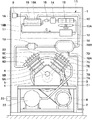
ここで、図1及び図2は第1の実施の形態を示し、本実施の形態では、空気圧縮装置としてパッケージ型の往復動圧縮装置を例に挙げて述べる。 Here, FIG. 1 and FIG. 2 show a first embodiment, and in this embodiment, a package type reciprocating compression device will be described as an example of an air compression device.
図中、1は空気圧縮装置の外殻を構成する防音箱で、この防音箱1は、例えば複数の鋼板等によって囲まれた略直方体の箱体として形成され、その内部には四角形の枠状をなす台座2が設けられている。
In the figure,
そして、台座2には、後述の圧縮機3、モータ8、貯留タンク22等が設けられ、これらの機器は後述の吸込側ドライヤ11、吸込タンク18、フィルタ19等と一緒に防音箱1内に収容されている。また、防音箱1の周壁には吸気用の開口部1Aが設けられている。
The
3は防音箱1内の台座2上に設けられた圧縮機を示し、この圧縮機3は、例えば2気筒・2段式の往復動圧縮機からなり、台座2上に取付けられたクランクケース4と、該クランクケース4に回転可能に設けられたクランク軸5と、後述の低圧気筒6,高圧気筒7とによって大略構成されている。
6はクランクケース4上に設けられた低圧気筒で、この低圧気筒6は、シリンダ6Aと、該シリンダ6A内に往復動可能に挿嵌され、連接棒等を介してクランク軸5に連結されたピストン6Bと、シリンダ6A上に搭載されたシリンダヘッド6Cと、該シリンダヘッド6Cに設けられた吸込ポート6D、吐出ポート6Eと、低圧気筒6内に開,閉可能に設けられた吸込弁,吐出弁(何れも図示せず)とを有している。
そして、低圧気筒6は、ピストン6Bがシリンダ6A内で往復動することにより、吸込行程と吐出行程とを交互に繰返す。この場合、吸込行程では、吸込弁が開弁して吐出弁が閉弁することにより、吸込ポート6Dからシリンダ6A内に空気が吸込まれ、この吸込空気はシリンダ6A内で圧縮されて圧縮空気となる。また、吐出行程では、吸込弁が閉弁して吐出弁が開弁することにより、シリンダ6A内の圧縮空気が吐出ポート6Eから吐出される。
The
7は低圧気筒6と並んでクランクケース4上に設けられた高圧気筒で、この高圧気筒7は、低圧気筒6とほぼ同様に、シリンダ7A、ピストン7B、シリンダブロック7C、吸込ポート7D、吐出ポート7E等を有している。
これらの気筒6,7において、低圧気筒6の吸込ポート6Dは、後述の吸込配管10、吸込側ドライヤ11、吸込タンク18、フィルタ19等を介して吸込口9に接続されている。また、低圧気筒6の吐出ポート6Eは、中間配管20を介して高圧気筒7の吸込ポート7Dに接続されている。さらに、高圧気筒7の吐出ポート7Eは、後述の吐出配管21、貯留タンク22等を介してエア供給口23に接続されている。
In these
そして、圧縮機3は、1段目の低圧気筒6によって吸込んだ空気を中間圧力まで圧縮し、この中間圧力の圧縮空気を2段目の高圧気筒7によってさらに圧縮することにより、吐出ポート7Eから貯留タンク22に向けて高圧の圧縮空気を吐出するものである。
Then, the
8は圧縮機3の駆動源を構成する電動式のモータで、該モータ8は、圧縮機3の下側に位置して台座2に設けられ、プーリ、ベルト等を介してクランク軸5と連結されている。そして、モータ8は、クランク軸5を回転駆動することにより、圧縮機3を作動させる。
9は防音箱1の開口部1Aの近傍に設けられた吸込口で、該吸込口9は、防音箱1の外部から開口部1Aを通じて外気を吸込むものである。この場合、吸込口9には、例えば防塵・防音機能を有するフィルタ等が設けられている。
10は圧縮機3の吸込側に設けられた吸込配管で、該吸込配管10は、低圧気筒6の吸込ポート6Dに空気を吸込むものであり、その一端側(上流側)には吸込口9が設けられている。また、吸込配管10の他端側(下流側)は低圧気筒6の吸込ポート6Dに接続されている。
また、吸込配管10の途中には、図1、図2に示す如く、後述の吸込側ドライヤ11、吸込タンク18及びフィルタ19が設けられている。そして、吸込口9から吸込まれた外気(吸込空気)は、吸込配管10を流通することによって吸込側ドライヤ11、吸込タンク18及びフィルタ19を順次通過し、その後に低圧気筒6の吸込ポート6Dに吸込まれる。
Further, as shown in FIGS. 1 and 2, a suction-
11は圧縮機3の吸込側に設けられた水分除去手段としての吸込側ドライヤを示している。この吸込側ドライヤ11は、低圧気筒6の吸込ポート6Dに空気が吸込まれるときに当該吸込空気を冷媒Cによって冷却し、これによって吸込空気の除湿を行うものである。そして、吸込側ドライヤ11は、例えば冷凍式のドライヤ等からなり、後述の冷媒圧縮機12、凝縮器13、レシーバタンク14、膨張弁15、熱交換器16、冷媒配管17等によって構成されている。
12は例えば電動式のコンプレッサ等からなる冷媒圧縮機で、該冷媒圧縮機12は、後述の如く熱交換器16内で気化した冷媒Cを圧縮し、高圧な気体となった冷媒Cを凝縮器13に向けて吐出するものである。
13は冷媒圧縮機12の吐出側に接続された凝縮器で、該凝縮器13は、例えば冷媒配管17の途中に接続されたジグザグ状の冷媒用管路(図示せず)と、冷媒圧縮機12から前記冷媒用管路に流入する冷媒Cを冷却する電動ファン13Aとを有している。そして、凝縮器13によって冷却された冷媒Cは、冷媒配管17の途中に設けられたレシーバタンク14内に容され、その後に膨張弁15によって減圧されることにより、液化した状態で熱交換器16に向けて流通する。
16は凝縮器13の流出側に接続された熱交換器で、該熱交換器16は、吸込配管10の途中に接続されるエア通路16Aと、該エア通路16Aの近傍に位置して例えばジグザグ状に屈曲して形成され、冷媒配管17の途中に接続された冷媒通路16B(図1では形状を簡略化)とを有している。
16 is a heat exchanger connected to the outflow side of the
そして、熱交換器16は、液化状態の冷媒Cが膨張弁15側から冷媒通路16Bに流入するときに、この冷媒Cをエア通路16Aの近傍で気化させることにより、エア通路16Aを流れる吸込空気を冷却する。このため、吸込空気中に含まれる水分はエア通路16Aの周壁等で結露し、その水滴は熱交換器16に設けられたドレン通路(図示せず)等によって外部に排出される。
Then, when the liquefied refrigerant C flows into the
このように、吸込側ドライヤ11は吸込空気中に含まれる水分を除去し、吸込空気を乾燥させる。また、冷媒通路16B内で気化した冷媒Cは、冷媒配管17を通じて冷媒圧縮機12に還流される。この場合、冷媒配管17は、冷媒圧縮機12、凝縮器13、レシーバタンク14、膨張弁15及び熱交換器16を環状に接続し、これらの間で冷媒Cを循環させるものである。
Thus, the
次に、18は吸込側ドライヤ11と圧縮機3との間に設けられた吸込タンクを示し、該吸込タンク18は吸込側ドライヤ11の下流側に接続され、このドライヤ11によって冷却された吸込空気が流通するものである。そして、吸込タンク18は、低音となった吸込空気中に含まれる水分を当該タンク18の内壁に結露させ、これによって吸込空気をさらに乾燥させる。このため、吸込タンク18には、結露した水滴を外部に排出するドレン排出口18Aが設けられている。
Next, 18 denotes a suction tank provided between the
また、吸込タンク18の外側には断熱材18Bが設けられ、この断熱材18Bは、空気圧縮装置を運転することによって防音箱1内の空気の温度が上昇したときに、その熱が吸込タンク18に伝導するのを抑制している。これにより、吸込タンク18内で吸込空気が暖まるのを防止することができる。
Further, a
さらに、圧縮機3の運転時には、吸込行程が周期的に繰返されることにより吸込空気の圧力に脈動が生じ、この脈動が吸込配管10内で共振状態となると、圧縮機3内の吸込弁や吐出弁が大きな圧力変動を受けて損傷する虞れがある。このため、吸込タンク18は、吸込配管10の途中に適度な容積をもって介在し、圧縮機3の上流側で吸込空気の圧力変動を吸収する構成となっている。
Further, during the operation of the
19は圧縮機3の吸込側に設けられたフィルタで、該フィルタ19は、例えば吸込タンク18の下流側に配置されている。そして、フィルタ19は吸込空気中に含まれる塵埃等を除去し、また圧縮機3の吸込側から騒音(作動音)が外部に漏れるのを防止するものである。
一方、20は低圧気筒6の吐出ポート6Eと高圧気筒7の吸込ポート7Dとを接続する中間配管で、該中間配管20は、低圧側の吐出ポート6Eから吐出される中間圧の圧縮空気を高圧側の吸込ポート7Dに吸込ませる。
On the other hand, 20 is an intermediate pipe that connects the
21は圧縮機3の吐出側に設けられた吐出配管で、該吐出配管21は、一端側が高圧気筒7の吐出ポート7Eに接続され、この吐出ポート7Eから吐出される圧縮空気が流通するものである。また、吐出配管21の他端側は、圧縮空気を貯える貯留タンク22を経由してエア供給口23に接続され、該エア供給口23は、外部の空圧機器(図示せず)等に圧縮空気を供給する構成となっている。
本実施の形態によるパッケージ型の空気圧縮装置は上述の如き構成を有するもので、次にその作動について説明する。 The package type air compressor according to the present embodiment has the above-described configuration, and the operation thereof will be described next.
まず、モータ8が作動すると、その回転がプーリ、ベルト等を介して圧縮機3のクランク軸5に伝達されることにより、各気筒6,7のシリンダ6A,7A内でピストン6B,7Bがそれぞれ往復動する。これにより、吸込口9から外気が吸込まれると、この吸込空気は、吸込側ドライヤ11、吸込タンク18及びフィルタ19を順次流通した後に、低圧気筒6の吸込ポート6Dに吸込まれる。
First, when the
このとき、吸込空気は、吸込側ドライヤ11と吸込タンク18とを通過することによって水分が除去されるので、低圧気筒6内には、湿度の低い乾燥した吸込空気が流入する。これにより、低圧気筒6内に配置された吸込弁、吐出弁、軸受、シール、潤滑剤(潤滑油)等の部品を湿気から保護することができ、湿気による部品の錆び、品質の劣化等を抑えて各部品の寿命を延ばすことができる。
At this time, since the moisture is removed from the suction air by passing through the suction-
そして、この吸込空気は、低圧気筒6のシリンダ6A内で圧縮されて中間圧の圧縮空気となり、さらに高圧気筒7のシリンダ7A内で圧縮されることにより、高圧な圧縮空気となる。そして、この高圧な圧縮空気は、吐出配管21を通じて貯留タンク22内に貯えられ、必要に応じてエア供給口23から外部の空圧機器等に供給される。
The intake air is compressed in the
この場合、各気筒6,7内に吸込まれた空気は、断熱状態で圧縮されることによって温度がそれぞれ上昇する。しかし、これらの空気は吸込側ドライヤ11によって予め冷却しておくことができるから、個々の気筒6,7から吐出される圧縮空気の温度を最初に予冷した分だけ低下させることができる。
In this case, the temperature of the air sucked into each of the
これにより、圧縮機3の運転時には、圧縮空気が到達し得る最高温度を全体的に低くすることができ、各気筒6,7に配置される例えば軸受、シール、潤滑油等の部品を高温から保護することができる。このため、各部品の熱劣化を抑えることができ、部品の寿命を延ばして耐久性や信頼性を高めることができる。
Thereby, when the
また、各気筒6,7には、低い温度の吸込空気を熱膨張を抑えた状態で十分な量だけ吸込むことができ、圧縮効率を高めることができる。これにより、空気圧縮装置の耐熱性を確保しつつ、その高圧化、高性能化を実現することができる。
In addition, the
かくして、本実施の形態によれば、圧縮機3の吸込側に冷凍式の吸込側ドライヤ11を設ける構成としたので、圧縮機3の運転時には、吸込側ドライヤ11によって吸込空気中に含まれる水分を除去することができ、圧縮機3には、湿度の低い吸込空気を安定的に流入させることができる。
Thus, according to the present embodiment, since the refrigeration-type suction-
これにより、例えば圧縮機3内の吸込弁、吐出弁が湿気によって錆びたり、潤滑剤(潤滑油)が湿気によって劣化するのを確実に防止することができ、これらの部品を長期間にわたって安定的に作動させることができる。従って、多湿な環境等に対しても適応性の高い空気圧縮装置を実現することができ、その圧縮性能や耐久性、信頼性を向上させることができる。
As a result, for example, the suction valve and the discharge valve in the
この場合、水分除去手段として、冷凍式ドライヤ等からなる吸込側ドライヤ11を用いたので、吸込側ドライヤ11は、冷媒Cによって吸込空気を冷却しつつ、当該空気中に含まれる水分を結露させて除去することができ、圧縮機3に流入する吸込空気を効率よく乾燥させることができる。
In this case, since the suction-
また、吸込側ドライヤ11を用いることにより、最初に吸込空気を予冷した分だけ圧縮空気の温度を低下させることができる。このため、圧縮機3の部品が高温によって劣化するのを防止でき、耐熱性を高めることができる。また、圧縮機3には、熱膨張を抑えた低い温度の吸込空気を十分に吸込むことができるから、圧縮効率を高めることができ、空気圧縮装置の高性能化(高圧化)を実現することができる。
Further, by using the
また、圧縮機3と吸込側ドライヤ11との間には吸込タンク18を設けたので、吸込側ドライヤ11から圧縮機3に向けて吸込空気が流れるときには、その流通経路の途中に吸込タンク18を介在させることができる。これにより、吸込タンク18は、低温となった吸込空気中に含まれる水分を当該タンク18の内壁等に結露させて除去することができ、吸込側ドライヤ11と協働して吸込空気を効率よく乾燥させることができる。
In addition, since the
また、例えば吸込配管10内で吸込空気の圧力に脈動が生じたとしても、この脈動を吸込タンク18によって吸収することができ、圧縮機3側では脈動の影響を緩和することができる。このため、例えば圧縮機3内の吸込弁、吐出弁等を過大な圧力変動から保護することができ、これらの部品の損傷を防止して耐久性を高めることができる。
For example, even if pulsation occurs in the pressure of the intake air in the
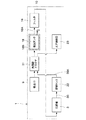
次に、図3及び図4は本発明による第2の実施の形態を示し、本実施の形態の特徴は、吸込側ドライヤの他に吐出側ドライヤを設け、これらのドライヤを共用化する構成としたことにある。なお、本実施の形態では、前記第1の実施の形態と同一の構成要素に同一の符号を付し、その説明を省略するものとする。 Next, FIGS. 3 and 4 show a second embodiment according to the present invention. The feature of this embodiment is that a discharge-side dryer is provided in addition to the suction-side dryer, and these dryers are shared. It is to have done. In the present embodiment, the same components as those in the first embodiment are denoted by the same reference numerals, and the description thereof is omitted.
30は圧縮機3の吐出側に設けられた吐出配管で、該吐出配管30は、貯留タンク22の上流側に位置する部位が第1の実施の形態とほぼ同様に形成されているものの、貯留タンク22の下流側に位置する部位には、後述の共用型ドライヤ31に向けて延びた延長配管部30Aが設けられている。
31は第1の実施の形態の吸込側ドライヤ11に代えて本実施の形態で用いられる水分除去手段としての共用型ドライヤを示している。この共用型ドライヤ31は、第1の実施の形態とほぼ同様の冷凍式ドライヤ等からなり、冷媒圧縮機12、凝縮器13、レシーバタンク14、膨張弁15、冷媒配管17と、後述の熱交換器32とによって構成されている。
しかし、共用型ドライヤ31は、圧縮機3の吸込側に設けられる吸込側ドライヤと、圧縮機3の吐出側に設けられる吐出側ドライヤとを共用化したもので、吸込空気と圧縮空気とを共通の冷媒Cによって冷却することにより、これらの空気の除湿を一緒に行うものである。
However, the shared
32は凝縮器13の流出側に接続された熱交換器で、この熱交換器32は、吸込配管10の途中に接続される吸込側エア通路32Aと、吐出配管30の延長配管部30Aの途中に接続される吐出側エア通路32Bと、これら2つのエア通路32A,32Bの近傍に配置され、冷媒配管17の途中に接続された冷媒通路32Cとを有している。
32 is a heat exchanger connected to the outflow side of the
そして、熱交換器32は、液化状態の冷媒Cをエア通路32A,32Bの近傍で気化させることにより、吸込側エア通路32Aを流れる吸込空気と、吐出側エア通路32Bを流れる圧縮空気とを一緒に冷却する。このため、吸込空気及び圧縮空気に含まれる水分は、個々のエア通路32A,32B内でそれぞれ結露し、ドレン通路(図示せず)等から外部に排出される。このように、共用型ドライヤ31は、吸込空気と圧縮空気とを乾燥させることができる。
The
かくして、このように構成される本実施の形態でも、前記第1の実施の形態とほぼ同様の作用効果を得ることができる。そして、特に本実施の形態では、共用型ドライヤ31を用いる構成としたので、この共用型ドライヤ31によって圧縮空気の除湿も行うことができ、例えば外部の空圧機器等に向けて湿度の低い圧縮空気を安定的に供給することができる。従って、圧縮機3だけでなく、これと接続される外部の機器等についても部品の錆び、劣化等を抑制することができ、空圧源として取扱いが容易な空気圧縮装置を実現することができる。
Thus, in the present embodiment configured as described above, it is possible to obtain substantially the same operational effects as those of the first embodiment. In particular, in the present embodiment, since the shared
また、共用型ドライヤ31によって吸込側ドライヤと吐出側ドライヤとを共用化することができるから、防音箱1内には、これら2つのドライヤをそれぞれ個別に配置する必要がなくなり、ドライヤに関連した部品点数や部品の配置スペース等を削減することができる。従って、吸込側と吐出側の両方にドライヤの機能を備えた空気圧縮装置であっても、これをコンパクトに形成することができ、また圧縮装置の組立作業を効率よく行うことができる。
Further, since the suction-side dryer and the discharge-side dryer can be shared by the shared
しかも、例えば従来技術のように吐出側ドライヤが予め搭載されている空気圧縮装置の場合には、吸込配管10の一部を既存の吐出側ドライヤの位置に延ばして当該ドライヤに接続することができ、これによって吸込側のドライヤも形成することができる。このため、既存の吐出側ドライヤを利用して共用型ドライヤ31を容易に実現することができ、コストアップを抑えることができる。
In addition, for example, in the case of an air compressor in which a discharge-side dryer is mounted in advance as in the prior art, a part of the
なお、前記第2の実施の形態では、吸込側と吐出側のドライヤを共用型ドライヤ31として構成する場合を例に挙げて述べた。しかし、本発明はこれに限らず、例えば図5に示す変形例のように、吸込空気を冷媒によって冷却し当該吸込空気の除湿を行う吸込側ドライヤ11と、圧縮空気を冷媒によって冷却し当該圧縮空気の除湿を行う吐出側ドライヤ41とをそれぞれ個別の冷凍式ドライヤによって構成してもよい。
In the second embodiment, the case where the suction-side and discharge-side dryers are configured as the shared
また、実施の形態では、吸込側ドライヤ11(共用型ドライヤ31)と圧縮機3との間に吸込タンク18とフィルタ19とを設ける構成とした。しかし、本発明は必ずしも吸込タンク18を用いる必要はなく、例えば吸込タンク18を搭載しない仕様の空気圧縮装置を構成してもよい。また、本発明のフィルタ19は、圧縮機3の吸込側(上流側)であれば任意の位置に接続してよいものであり、例えばフィルタ19を吸込口9に取付ける構成としてもよい。
In the embodiment, the
また、実施の形態では、水分除去手段として、冷凍式のドライヤ11,31を用いる構成とした。しかし、本発明の水分除去手段は冷凍式ドライヤに限らず、例えばシリカゲル等の除湿剤により水分を吸着して除去する吸着式のドライヤを用いる構成としてもよい。また、ドライヤ以外の水分除去手段を用いてもよく、例えば空気(冷却風)によって吸込配管10を冷却するクーラ装置等を水分除去手段として用いる構成としてもよい。
In the embodiment, the
さらに、実施の形態では、空気圧縮装置として、パッケージ型の2気筒・2段式往復動圧縮装置を例に挙げて説明した。しかし、本発明はこれに限らず、例えば単気筒または2気筒の圧縮機や、1段式の圧縮機、またはスクロール式の圧縮機を搭載した空気圧縮装置に適用してもよく、さらにはパッケージ型以外の空気圧縮装置にも広く適用することができる。 Furthermore, in the embodiment, the package type two-cylinder / two-stage reciprocating compressor has been described as an example of the air compressor. However, the present invention is not limited to this, and may be applied to, for example, a single-cylinder or two-cylinder compressor, a single-stage compressor, or an air compressor equipped with a scroll compressor. It can be widely applied to air compression devices other than molds.
1 防音箱
3 圧縮機
6,7 気筒
8 モータ
9 吸込口
10 吸込配管
11 吸込側ドライヤ(水分除去手段)
12 冷媒圧縮機
13 凝縮器
14 レシーバタンク
15 膨張弁
16,32 熱交換器
16A,32A,32B エア通路
16B,32C 冷媒通路
17 冷媒配管
18 吸込タンク
18A ドレン排出口
18B 断熱材
19 フィルタ
20 中間配管
21,30 吐出配管
22 貯留タンク
23 エア供給口
31 共用型ドライヤ(水分除去手段)
41 吐出側ドライヤ
C 冷媒
DESCRIPTION OF
DESCRIPTION OF
41 Discharge side dryer C Refrigerant
Claims (5)
The air compressor according to claim 1, 2, 3, or 4, wherein a suction tank through which suction air flows is provided between the moisture removing means and the compressor.
Priority Applications (1)
| Application Number | Priority Date | Filing Date | Title |
|---|---|---|---|
| JP2005346571A JP2007154663A (en) | 2005-11-30 | 2005-11-30 | Air compression device |
Applications Claiming Priority (1)
| Application Number | Priority Date | Filing Date | Title |
|---|---|---|---|
| JP2005346571A JP2007154663A (en) | 2005-11-30 | 2005-11-30 | Air compression device |
Publications (1)
| Publication Number | Publication Date |
|---|---|
| JP2007154663A true JP2007154663A (en) | 2007-06-21 |
Family
ID=38239374
Family Applications (1)
| Application Number | Title | Priority Date | Filing Date |
|---|---|---|---|
| JP2005346571A Pending JP2007154663A (en) | 2005-11-30 | 2005-11-30 | Air compression device |
Country Status (1)
| Country | Link |
|---|---|
| JP (1) | JP2007154663A (en) |
Cited By (4)
| Publication number | Priority date | Publication date | Assignee | Title |
|---|---|---|---|---|
| JP2012241719A (en) * | 2011-05-20 | 2012-12-10 | Linde Ag | Method and apparatus for compressing gaseous medium in single or multiple stages |
| KR101581927B1 (en) * | 2015-02-06 | 2015-12-31 | 나한도 | Water Removing Apparatus before Air Compressing of Compressor |
| CN108167639A (en) * | 2017-12-26 | 2018-06-15 | 广东万合汽车供应链管理有限公司 | A kind of air reservoir of the convenient semitrailer of damping gas storage |
| CN111336095A (en) * | 2020-03-21 | 2020-06-26 | 湖北金雄节能科技股份有限公司 | Air compressor machine protection device |
Citations (3)
| Publication number | Priority date | Publication date | Assignee | Title |
|---|---|---|---|---|
| JPH04325796A (en) * | 1991-04-26 | 1992-11-16 | Hitachi Ltd | Oil fed type screw compressor |
| JP2000205134A (en) * | 1999-01-18 | 2000-07-25 | Kobe Steel Ltd | Air compressor |
| JP2005264886A (en) * | 2004-03-22 | 2005-09-29 | Isuzu Motors Ltd | Suction noise reducing structure of air compressor |
-
2005
- 2005-11-30 JP JP2005346571A patent/JP2007154663A/en active Pending
Patent Citations (3)
| Publication number | Priority date | Publication date | Assignee | Title |
|---|---|---|---|---|
| JPH04325796A (en) * | 1991-04-26 | 1992-11-16 | Hitachi Ltd | Oil fed type screw compressor |
| JP2000205134A (en) * | 1999-01-18 | 2000-07-25 | Kobe Steel Ltd | Air compressor |
| JP2005264886A (en) * | 2004-03-22 | 2005-09-29 | Isuzu Motors Ltd | Suction noise reducing structure of air compressor |
Cited By (4)
| Publication number | Priority date | Publication date | Assignee | Title |
|---|---|---|---|---|
| JP2012241719A (en) * | 2011-05-20 | 2012-12-10 | Linde Ag | Method and apparatus for compressing gaseous medium in single or multiple stages |
| KR101581927B1 (en) * | 2015-02-06 | 2015-12-31 | 나한도 | Water Removing Apparatus before Air Compressing of Compressor |
| CN108167639A (en) * | 2017-12-26 | 2018-06-15 | 广东万合汽车供应链管理有限公司 | A kind of air reservoir of the convenient semitrailer of damping gas storage |
| CN111336095A (en) * | 2020-03-21 | 2020-06-26 | 湖北金雄节能科技股份有限公司 | Air compressor machine protection device |
Similar Documents
| Publication | Publication Date | Title |
|---|---|---|
| US6769267B2 (en) | Multistage compressor | |
| US7241121B2 (en) | Scroll fluid machine | |
| JP5027130B2 (en) | Multi-cylinder dry piston compressor with cooling air flow | |
| TW200305687A (en) | Multistage rotary compressor and refrigeration circuit system | |
| KR101215607B1 (en) | Hermetic compressor with a heat dissipation system | |
| US20060130512A1 (en) | Cooling-cycle device and cold/hot water dispenser comprising the same | |
| JP2007154663A (en) | Air compression device | |
| KR101012946B1 (en) | Multi-stage gas compressing apparatus | |
| JP2010185342A (en) | Rotary motor-driven compressor | |
| JP2007100534A (en) | Package compressor | |
| US20180195503A1 (en) | Fluid compressor | |
| JP3291469B2 (en) | Rotary compressor | |
| WO2019129432A1 (en) | A hermetic compressor | |
| JP2009108747A (en) | Hermetic electric compressor | |
| JP4606272B2 (en) | Cooling system electric compressor | |
| US20020110463A1 (en) | Horizontal closed type compressor for vehicle use and cooling system of electric compressor for vehicle use | |
| KR100711637B1 (en) | Compressor | |
| JP3631006B2 (en) | Rotary compressor | |
| JP4726444B2 (en) | Multi-cylinder rotary compressor | |
| JP3695963B2 (en) | Rotary compressor | |
| JP5032057B2 (en) | Dehumidifier | |
| KR200356283Y1 (en) | Compressor | |
| KR200351087Y1 (en) | Compressor | |
| KR200320308Y1 (en) | An apparatus for supply of compressed air | |
| JP4359164B2 (en) | 2-stage rotary compressor |
Legal Events
| Date | Code | Title | Description |
|---|---|---|---|
| A621 | Written request for application examination |
Effective date: 20080926 Free format text: JAPANESE INTERMEDIATE CODE: A621 |
|
| A521 | Written amendment |
Free format text: JAPANESE INTERMEDIATE CODE: A821 Effective date: 20080930 |
|
| A131 | Notification of reasons for refusal |
Free format text: JAPANESE INTERMEDIATE CODE: A131 Effective date: 20100928 |
|
| A977 | Report on retrieval |
Free format text: JAPANESE INTERMEDIATE CODE: A971007 Effective date: 20100930 |
|
| A02 | Decision of refusal |
Effective date: 20110208 Free format text: JAPANESE INTERMEDIATE CODE: A02 |