JP2007149190A - Optical pickup device - Google Patents
Optical pickup device Download PDFInfo
- Publication number
- JP2007149190A JP2007149190A JP2005340183A JP2005340183A JP2007149190A JP 2007149190 A JP2007149190 A JP 2007149190A JP 2005340183 A JP2005340183 A JP 2005340183A JP 2005340183 A JP2005340183 A JP 2005340183A JP 2007149190 A JP2007149190 A JP 2007149190A
- Authority
- JP
- Japan
- Prior art keywords
- light
- diffraction
- region
- dividing line
- light receiving
- Prior art date
- Legal status (The legal status is an assumption and is not a legal conclusion. Google has not performed a legal analysis and makes no representation as to the accuracy of the status listed.)
- Pending
Links
Images


Landscapes
- Optical Recording Or Reproduction (AREA)
- Optical Head (AREA)
Abstract
Description
本発明は、対物レンズシフト及び回折素子と受光素子との位置合わせずれにより生じるトラッキングエラー信号を補正する光ピックアップ装置に関する。 The present invention relates to an optical pickup device that corrects a tracking error signal caused by an objective lens shift and a misalignment between a diffraction element and a light receiving element.
トラッキングエラー信号を用いてトラッキングサーボを行う光ピックアップ装置は、特許文献1に記載されている。特許文献1に記載されている光ピックアップ装置について、図9及び図10を用いて説明する。
図9は、特許文献1に記載されている光ピックアップ装置の概略図である。図10は、回折素子と第2光検出器との位置関係を示す斜視図である。
即ち、図9に示すように、特許文献1に記載の光ピックアップ装置は、光ディスクEにレーザ光を出射する半導体レーザ100と、レーザ光を平行にするコリメートレンズ101と、このコリメートレンズ101で平行にされたレーザ光を透過し、光ディスクEで反射されたレーザ光を反射する偏光分離膜102Aを有した第1偏光ビームスプリッタ102と、第1偏光ビームスプリッタ102の偏光分離膜102Aを透過したレーザ光を光ディスクEに集光する対物レンズ103と、第1偏光ビームスプリッタ102の偏光分離膜102Aで反射された光ディスクEからの反射光のうち光磁気信号を含んだ成分の光を反射し、それ以外の光を透過する偏光分離膜104Aを有する第2偏光ビームスプリッタ104と、を有している。
An optical pickup device that performs tracking servo using a tracking error signal is described in Patent Document 1. The optical pickup device described in Patent Document 1 will be described with reference to FIGS.
FIG. 9 is a schematic diagram of an optical pickup device described in Patent Document 1. FIG. 10 is a perspective view showing the positional relationship between the diffraction element and the second photodetector.
That is, as shown in FIG. 9, the optical pickup device described in Patent Document 1 includes a
更に、この光ピックアップ装置は、第2偏光ビームスプリッタ104の偏光分離膜104Aで反射された光磁気信号を含んだ成分の光を2つの偏光成分に分離する分離膜105Aを有するウォラストンプリズム105と、2つの受光素子106A、106Bを有する第1光検出器106に集光するスポットレンズ107と、第2偏光ビームスプリッタ104の偏光分離膜104Aを透過した光磁気信号を含まない光を回折する回折素子108と、回折素子108で回折された±1次回折光、0次光をシリンドリカルレンズ109、スポットレンズ110を介して検出する第2光検出器111と、を有している。
2つの受光素子106A、106Bは、ウォラストンプリズム105の分離膜105Aで分離された2つの偏光成分を検出して光ディスクEの情報を再生する。
図10に示すように、第2光検出器111は、中央部に十字状に分割された4つの受光領域M〜Pを有する第1受光部111Aと、第1受光部111Aの両側に所定の距離隔てて配置された一対の第2、第3受光部111B、111Cとを有している。
Further, this optical pickup device includes a Wollaston
The two
As shown in FIG. 10, the
回折素子108は、格子ピッチが同一であり、かつ山部分の幅と谷部の幅とのデューティ比が一方向に減少又は増加しており、その比率が大きい方側では、±1次回折光は減少し、0次回折光は増加する構成を有している。
In the
この光ピックアップ装置を用いたフォーカスエラー信号は、光ディスクから反射され、回折素子108で回折された光が第2光検出器111における第1の受光部111Aの4つの受光領域で光電変換されて出力された信号から、非点収差法により求めることができる。
The focus error signal using this optical pickup device is reflected from the optical disk, and the light diffracted by the
一方、トラッキングエラー信号は、以下のようにして求めることができる。
まずは、対物レンズ103のオフセットを補正するためのオフセット補正信号を求める。オフセット補正信号は、第1受光部111Aの4つの受光領域M〜Pで光電変換された信号を加算して得られた第1加算値から第2、第3受光部111B、111Cで光電変換された信号を加算して得られた第2加算値に所定ゲインを乗算した乗算値を減算して求められる。
このオフセット補正信号は、対物レンズ103のシフトの方向と量によって正負に変化する。
On the other hand, the tracking error signal can be obtained as follows.
First, an offset correction signal for correcting the offset of the
This offset correction signal changes positively and negatively depending on the direction and amount of shift of the
次に、第1受光部111の4つの受光領域M〜Pのうち、光ディスクEのトラック方向と平行に分割された一方の2つの受光領域で光電変換された信号同士を加算した第3加算値から他方の2つの受光領域で光電変換された信号同士を加算した第4加算値を減算してプッシュプル信号を求める。
Next, among the four light receiving areas M to P of the first
次に、上記したプッシュプル信号からオフセット補正信号に所定の定数を乗算した乗算値を減算することにより、トラッキングエラー信号を得ることができる。
しかしながら、回折素子108で回折された0次光が第1受光部111Aの4つの受光領域M〜P上に跨って入射する必要があるので、回折素子108と第1受光部111Aの数μm程度の微小な位置合わせずれを生じた場合でも、トラッキングエラー信号のオフセットを解消できない。
また、フォーカスエラー検出を行うのに非点収差法を用いているため、ウォラストンプリズム105及び第1光検出器106が必要となり安価な光ピックアップ装置を提供することができなかった。
そこで、本発明は、前述の課題に鑑みて提案されるものであって、回折素子と光検出器との位置合わせにμmオーダーのずれを生じても良好なトラッキングエラー検出を行うことができ、かつ安価な光ピックアップ装置を提供することを目的とする。
However, since the 0th-order light diffracted by the
In addition, since the astigmatism method is used to perform focus error detection, the Wollaston
Therefore, the present invention is proposed in view of the above-described problems, and can perform good tracking error detection even if a deviation of the order of μm occurs in the alignment between the diffraction element and the photodetector. Another object of the present invention is to provide an inexpensive optical pickup device.
本願発明における第1の発明は、レーザ光を光ディスクのトラックに集光する対物レンズと、前記トラックで反射された反射光から回折光を生成する回折素子と、複数の受光領域を有し、前記回折光を受光して光電変換する光検出器と、を備え、前記各受光領域で光電変換された信号を用いてトラッキングエラー検出及びフォーカスエラー検出を行う光ピックアップ装置において、前記回折素子は、光透過性基板の一方の面に形成され、前記反射光を回折して0次光及び±1次回折光を生成する第1回折部と、前記光透過性基板の他方の面に形成された回折領域を有し、かつ前記第1回折部で生成された前記0次光を回折する第2回折部と、前記第1回折部で生成された前記±1次回折光を分岐する第3、第4回折部と、を備え、前記第2回折部の回折領域は、第1〜第8回折領域からなり、前記回折領域を前記光ディスクのトラック方向と平行に2等分割する分割線を第1分割線、前記トラック方向に平行で、かつ前記第1分割線から等距離に形成された分割線を第2、第3分割線、前記光ディスクのラジアル方向と平行に2等分割する分割線を第4分割線、前記ラジアル方向に平行で、かつ第4分割線から等距離に形成された分割線を第5、第6分割線とするとき、前記第1回折領域は、前記第2分割線、前記第4分割線、前記第5分割線及び前記回折領域の外周縁で囲まれた領域、前記第2回折領域は、前記第2分割線、前記第4分割線、前記第6分割線及び前記回折領域の外周縁で囲まれた領域、前記第3回折領域は、前記第3分割線、前記第4分割線、前記第5分割線及び前記回折領域の外周縁で囲まれた領域、第4回折領域は、前記第3分割線、前記第4分割線、前記第6分割線及び前記回折領域の外周縁で囲まれた領域、前記第5回折領域は、前記第1分割線、前記第5分割線、前記回折領域の外周縁で囲まれた第1領域、前記第6回折領域は、前記第1分割線、前記第6分割線、前記回折領域の外周縁で囲まれた第3領域、前記第7回折領域は、前記第1分割線、前記第5分割線及び前記回折領域の外周縁で囲まれた第2領域、前記第8回折領域は、前記第1分割線、前記第6分割線及び前記回折領域の外周縁で囲まれた第4領域であり、前記光検出器は、前記第1回折領域で回折された−1次回折光及び前記第7、第8回折領域で回折された+1次回折光を検出する第1受光領域と、前記第2回折領域、前記第7回折領域及び前記第8回折領域で回折された−1次回折光を検出する第2受光領域と、前記第3回折領域、前記第5、第6回折領域で回折された+1次回折光を検出する第3受光領域と、前記第4回折領域で回折された+1次回折光及び前記第5、第6回折領域で回折された−1次回折光を検出する第4受光領域と、前記第3、第4回折部で分岐された分岐光を検出する第2、第3受光部と、を備えたことを特徴とする光ピックアップ装置を提供する。
第2の発明は、前記第3、第4回折部のそれぞれは、前記反射光のスポット径と同一の大きさの第1円形回折領域と、前記第1円形回折領域を取り囲むように形成された第2円形回折領域と、を有することを特徴とする請求項1記載の光ピックアップ装置を提供する。
第3の発明は、前記2受光部は、ラジアル方向と平行に2等分割された第5、第6受光領域を有し、前記第5受光領域は、前記第3回折部における第1円形回折領域から射出された第1の射出光を検出し、前記第6受光領域は、前記第2円形回折領域から射出された第2の射出光を検出し、前記第3受光部は、ラジアル方向と平行に2等分割された第7、第8受光領域を有し、前記7受光領域は、前記第4回折部における第1円形回折領域から射出された第3の射出光を検出し、前記第8受光領域は、前記第2円形回折領域から射出された第4の射出光を検出することを特徴とする請求項2記載の光ピックアップ装置を提供する。
第4の発明は、前記第1回折部は、前記光ディスクの反射光から生成した前記±1次回折光のうちの一方を前記第3回折部或いは前記第4回折部の手前に集光させ、他方を前記第3回折部或いは前記第4回折部の前記光検出器側に集光させる回折領域を有していることを特徴とする請求項1乃至請求項3のいずれかに記載の光ピックアップ装置を提供する。
A first invention in the present invention comprises an objective lens that condenses laser light on a track of an optical disc, a diffraction element that generates diffracted light from reflected light reflected by the track, and a plurality of light receiving regions, A light detector that photoelectrically converts diffracted light by receiving the diffracted light, and an optical pickup device that performs tracking error detection and focus error detection using a signal photoelectrically converted in each light receiving region. A first diffractive portion formed on one surface of the transmissive substrate and diffracting the reflected light to generate 0th order light and ± 1st order diffracted light; and a diffraction region formed on the other surface of the light transmissive substrate. And a second diffracting unit that diffracts the zero-order light generated by the first diffracting unit, and third and fourth diffractions that branch the ± first-order diffracted light generated by the first diffracting unit. And the second diffraction The diffraction region of the first portion includes first to eighth diffraction regions, a dividing line that divides the diffraction region into two equal parts parallel to the track direction of the optical disc is defined as a first dividing line, parallel to the track direction, and the first A dividing line formed at an equal distance from one dividing line is divided into second and third dividing lines, a dividing line dividing into two equal parts parallel to the radial direction of the optical disc is a fourth dividing line, parallel to the radial direction, and When the dividing lines formed equidistant from the four dividing lines are the fifth and sixth dividing lines, the first diffraction region includes the second dividing line, the fourth dividing line, the fifth dividing line, and the A region surrounded by an outer peripheral edge of the diffraction region, the second diffraction region includes the second dividing line, the fourth dividing line, the sixth dividing line, and a region surrounded by the outer peripheral edge of the diffraction region; Three diffraction regions are the third dividing line, the fourth dividing line, the fifth dividing line, and The region surrounded by the outer peripheral edge of the diffraction region and the fourth diffraction region are the third dividing line, the fourth dividing line, the sixth dividing line, and the region surrounded by the outer peripheral edge of the diffraction region, 5 diffraction regions, the first dividing line, the fifth dividing line, the first region surrounded by the outer periphery of the diffraction region, the sixth diffraction region, the first dividing line, the sixth dividing line, The third region and the seventh diffraction region surrounded by the outer peripheral edge of the diffraction region are the first dividing line, the fifth dividing line, and the second region surrounded by the outer peripheral edge of the diffraction region, the eighth. The diffraction region is a fourth region surrounded by the first dividing line, the sixth dividing line, and an outer peripheral edge of the diffraction region, and the photodetector is diffracted by the first diffraction region. A first light receiving region for detecting folding light and + 1st order diffracted light diffracted in the seventh and eighth diffraction regions, the second diffraction region, The second light receiving region for detecting the −1st order diffracted light diffracted in the seventh diffraction region and the 8th diffraction region, and the + 1st order diffracted light diffracted in the third diffraction region, the fifth and sixth diffraction regions, A third light receiving region to detect, a fourth light receiving region to detect + 1st order diffracted light diffracted in the fourth diffraction region and a −1st order diffracted light diffracted in the fifth and sixth diffraction regions, and the third, There is provided an optical pickup device comprising: second and third light receiving portions that detect branched light branched by a fourth diffraction portion.
In the second invention, each of the third and fourth diffracting portions is formed so as to surround the first circular diffraction region having the same size as the spot diameter of the reflected light, and the first circular diffraction region. The optical pickup device according to claim 1, further comprising a second circular diffraction region.
According to a third aspect of the invention, the two light receiving portions have fifth and sixth light receiving regions that are divided into two equal parts in parallel to the radial direction, and the fifth light receiving region is the first circular diffraction in the third diffraction portion. The first light emitted from the region is detected, the sixth light receiving region detects the second light emitted from the second circular diffraction region, and the third light receiving portion The seventh and eighth light receiving regions are divided into two equal parts in parallel, and the seven light receiving regions detect third emitted light emitted from the first circular diffraction region in the fourth diffractive portion, and The optical pickup device according to claim 2, wherein the eight light receiving regions detect the fourth emitted light emitted from the second circular diffraction region.
According to a fourth aspect of the invention, the first diffractive part condenses one of the ± first-order diffracted lights generated from the reflected light of the optical disc before the third diffractive part or the fourth diffractive part, 4. The optical pickup device according to claim 1, further comprising: a diffraction region that condenses light on the photodetector side of the third diffraction portion or the fourth diffraction portion. I will provide a.
本発明によれば、第2回折部は、第1〜第8回折領域を有し、第1〜第8回折領域から回折された回折光を光検出器の第1〜第4受光領域で受光するようにしているので、回折素子と光検出器との位置合わせにμmオーダーのずれを生じても良好なトラッキングエラー検出を行うことができ、かつ安価な光ピックアップ装置を提供することができる。また、第1回折部は、前記±1次回折光のうちの一方を前記第3回折部或いは前記第4回折部の手前に集光させ、他方を前記第3回折部或いは前記第4回折部の前記光検出器側に集光させる回折領域を有しているので、SSD法を用いたフォーカスエラー信号を得ることができる。 According to the present invention, the second diffractive portion has the first to eighth diffraction regions, and receives the diffracted light diffracted from the first to eighth diffraction regions by the first to fourth light receiving regions of the photodetector. Therefore, it is possible to provide a good tracking error detection even when a deviation of the order of μm occurs in the alignment between the diffraction element and the photodetector, and to provide an inexpensive optical pickup device. The first diffracting unit condenses one of the ± first-order diffracted lights in front of the third diffracting unit or the fourth diffracting unit and the other of the third diffracting unit or the fourth diffracting unit. Since it has a diffraction region to be condensed on the photodetector side, a focus error signal using the SSD method can be obtained.
以下、本発明に係る光ピックアップ装置の実施例について、図面を参照して詳細に説明する。
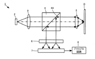
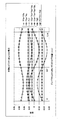
図1は、本発明に係る光ピックアップ装置を示す概略図である。図2は、回折素子と光検出器との関係を示す斜視図である。図3は、回折素子の第2回折部の各領域で回折される回折光の位置と光検出器の各受光領域に到達する位置との関係を示し、(A)は、第2回折部の分割された複数の回折領域を示す図、(B)は、第1検出部の各受光領域に到達する回折素子の各回折領域から出射された光との関係を示す図である。図4は、光検出器とプッシュプル回路との接続関係を示す図である。図5は、対物レンズシフトが0μmの場合のトラッキングエラー信号を示す図である。図6は、対物レンズシフトが150μmの場合のトラッキングエラー信号を示す図である。図7は、対物レンズシフトが300μmの場合のトラッキングエラー信号を示す図である。図8は、フォーカスエラー信号によるS字カーブを示す図である。
Hereinafter, embodiments of an optical pickup device according to the present invention will be described in detail with reference to the drawings.
FIG. 1 is a schematic view showing an optical pickup device according to the present invention. FIG. 2 is a perspective view showing the relationship between the diffraction element and the photodetector. FIG. 3 shows the relationship between the position of diffracted light diffracted in each region of the second diffractive portion of the diffractive element and the position reaching each light receiving region of the photodetector. The figure which shows the several divided diffraction area, (B) is a figure which shows the relationship with the light radiate | emitted from each diffraction area of the diffraction element which reaches | attains each light reception area | region of a 1st detection part. FIG. 4 is a diagram illustrating a connection relationship between the photodetector and the push-pull circuit. FIG. 5 is a diagram showing a tracking error signal when the objective lens shift is 0 μm. FIG. 6 is a diagram showing a tracking error signal when the objective lens shift is 150 μm. FIG. 7 is a diagram showing a tracking error signal when the objective lens shift is 300 μm. FIG. 8 is a diagram showing an S-shaped curve by the focus error signal.
図1に示すように、本発明に係る光ピックアップ装置1は、光ディスクDのトラックを照射するレーザ光を射出する半導体レーザ2と、半導体レーザ2から射出したレーザ光を平行光にするコリメートレンズ3と、レーザ光を透過し、光ディスクDからの反射光を反射させる偏光分離膜4Aを有する偏光ビームスプリッタ4と、偏光ビームスプリッタ4を透過したレーザ光を光ディスクDのトラックに集光させる対物レンズ5とから構成されている。対物レンズ5は、トラック方向に直交する方向(ラジアル方向)に移動可能である。
As shown in FIG. 1, an optical pickup device 1 according to the present invention includes a semiconductor laser 2 that emits laser light that irradiates a track of an optical disc D, and a
更に、光ピックアップ装置1は、偏光ビームスプリッタ4で反射された光ディスクDのトラックの反射光から回折光を生成する回折素子6と、回折素子6で生成された回折光を検出して光電変換する複数の受光領域を有する光検出器7と、光検出器で光電変換された信号からトラッキングエラー信号及びフォーカスエラー信号を生成するプッシュプル回路8とから構成されている。光ディスクDには、グルーブQとグルーブRが形成され、この場合のトラックは、グルーブQである。
Further, the optical pickup device 1 detects and photoelectrically converts the
以下に、回折素子6と光検出器7の構成及び配置関係について図2及び図3を用いて詳細に説明する。
まずは、回折素子6の構成について説明する。
図2に示すように、直方体状の光透過性基板9の一面9Aには、光ディスクDのトラックで反射された円形状の反射光から円形状の0次光と円形状の±1次回折光を生成する第1回折部10が形成され、他方の面9Bには、第1回折部10で生成された円形状の0次光から±1次回折光を生成する第2回折部11と、第1回折部10で生成された円形状の+1次回折光を所定角度で射出する第3回折部12と、第1回折部10で生成された円形状の−1次回折光を所定角度で射出する第4回折部13とから構成されている。
Below, the structure and arrangement | positioning relationship of the
First, the configuration of the
As shown in FIG. 2, on one
更に、第1回折部10には、光ディスクDの反射光から生成した円形状の±1次回折光のうちの一方を他方の面9Bの手前で焦点を結び、他方を他方の面9Bの後方で焦点を結ぶように回折領域が形成されている。このため、フォーカスエラー検出は、SSD法を用いることができるようになっている。
Further, the first
ここで、第1回折部10に入射する光ディスクDからの反射光について説明する。
光ディスクDのトラックを照射するレーザ光の光強度は、中央部では光強度が強く、周辺部で弱いガウス分布を有している。このため、光ディスクDのトラックからの反射光は、このガウス分布を保持した状態で、かつグルーブQとランドRの境界部で回折を生じた状態の光となる。
Here, the reflected light from the optical disc D that enters the
The light intensity of the laser light that irradiates the track of the optical disk D has a strong Gaussian distribution in the central part and a weak Gaussian distribution in the peripheral part. For this reason, the reflected light from the track of the optical disc D becomes light in a state where the Gaussian distribution is maintained and diffraction is generated at the boundary between the groove Q and the land R.
グルーブQの中央部からの反射光は、光強度が強いレーザ光がそのまま第1回折部10に入射し、グルーブQとこのグルーブQに隣接する両側のランドRとの境界部で回折した光は、グルーブQの中央部からの反射光の一部に重畳した状態で第1回折部10に入射する。この結果、図2に示すように、第1回折部10に入射する光ディスクDからの反射光は、グルーブQの中央部からの反射光L1と、グルーブQの中央部からの反射光の一部にグルーブQとこのグルーブQに隣接する両側のランドRとの境界部で回折した光が重畳した一対の反射光L2、L3とからなる。反射光L1及びグルーブQとランドRの境界部で回折した光も円形状であるので、一対の反射光L2、L3は、反射光L1とグルーブQとこのグルーブQに隣接するランドRの境界部で回折した光の共通部分で切り取られた光となり、ラグビーボール形状となる。
The reflected light from the central portion of the groove Q is a laser beam having a high light intensity that is incident on the first
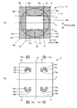
図3(A)に示すように、第2回折部11は、中央部に矩形開口部14A(回折領域でない領域)を有した正方形状の回折領域14からなる。
回折領域14は、第1〜第8回折領域S11〜S14、S21〜S24を有している。
第1〜第8回折領域S11〜S14、S21〜S24は以下の第1〜第6分割線15〜20で分割されている。
As shown in FIG. 3A, the second
The
The first to eighth diffraction regions S11 to S14 and S21 to S24 are divided by the following first to
各分割線について以下に説明する。
第1分割線15は、光ディスクDのトラック方向に2等分割する分割線であり、第2分割線16は、光ディスクDのトラック方向に平行で、かつな矩形状開口部14Aの一方の辺に接する分割線であり、第3分割線17は、光ディスクDのトラック方向に平行で、かつ矩形状開口部14Aの他方の辺に接する分割線であり、第4分割線18は、光ディスクDのラジアル方向に2等分割する分割線であり、第5分割線19は、光ディスクDのラジアル方向に平行で、かつ矩形状開口部14Aの一方の辺と直交する辺に接する分割線であり、第6分割線20は、光ディスクDのラジアル方向に平行で、かつ矩形状開口部14Aの他方の辺と直交する辺に接する分割線である。
Each dividing line will be described below.
The
第1回折領域S11は、第2分割線16、第4分割線18、第5分割線19及び回折領域14の第1外周縁14aとで囲まれた領域である。
第2回折領域S12は、第2分割線16、第4分割線18、第6分割線20及び回折領域14の第1外周縁14aで囲まれた領域である。
第3回折領域S21は、第3分割線17、第4分割線18、第5分割線19及び回折領域14の第2外周縁14bとで囲まれた領域である。
第4回折領域S22は、第3分割線17、第4分割線18、第6分割線20及び回折領域14の第2外周縁14bとで囲まれた領域である。
The first diffraction region S <b> 11 is a region surrounded by the
The second diffraction region S <b> 12 is a region surrounded by the
The third diffraction region S <b> 21 is a region surrounded by the
The fourth diffraction region S22 is a region surrounded by the
第5回折領域S13は、第1分割線15、第5分割線19及び回折領域14の第1、第3外周縁14a、14cで囲まれた領域である。
第6回折領域S14は、第1分割線15、第6分割線20及び回折領域14の第1、第4外周縁14a、14dで囲まれた領域である。
第7回折領域S23は、第1分割線15、第5分割線19及び回折領域14の第2、第3外周縁14b、14cで囲まれた領域である。
第8回折領域S24は、第1分割線15、第6分割線20及び回折領域14の第2、第4外周縁14b、14dで囲まれた領域である。
The fifth diffraction region S13 is a region surrounded by the
The sixth diffraction region S14 is a region surrounded by the
The seventh diffraction region S23 is a region surrounded by the
The eighth diffraction region S24 is a region surrounded by the
第2回折部11には、第1回折部10で生成された円形状の0次光、即ち反射光L1と、円形状の一対の反射光L2、L3がそのまま入射する。第1〜第8回折領域S11〜S14、S21〜S24の各回折領域には、第1反射光L1が入射し、第1、第2回折領域S11、S12には、反射光L2が入射し、第3、第4回折領域S21、S22には、反射光L3が入射するように形成されている。そして、矩形状開口部14Aの面する側の第1、第2回折領域S11、S12及び第3、第4回折領域の辺のそれぞれは、反射光L2、L3の接線となっている。
Circular second-order light generated by the first
レーザ光の波長をλとするとき、回折領域14は、一辺が6000λであり、第1分割線15から第2分割線16及び第3分割線17までの距離は、共に2000λである。第4分割線18から第5分割線19及び第6分割線20までの距離は、1000λである。
即ち、第1〜第4回折領域S11〜S14は、2000λ×2000λの正方形であり、第5〜第8回折領域S21〜S24は、3000λ×1000λの長方形である。
When the wavelength of the laser beam is λ, the side of the
That is, the first to fourth diffraction regions S11 to S14 are squares of 2000λ × 2000λ, and the fifth to eighth diffraction regions S21 to S24 are rectangles of 3000λ × 1000λ.
第3回折部12は、レーザ光が光ディスクDのトラックにジャストフォーカスした時の反射光が第1回折部10で生成された+1次回折光のスポット径と同じ大きさの第1円形回折部12Aと、第1円形回折部12Aを取り囲む第2円形回折部12Bとを有している。
第1回折部10で回折された+1次回折光は、第1、第2円形回折部12A、12Bに入射する。
The third diffracting
The + 1st order diffracted light diffracted by the first diffracting
第4回折部13は、レーザ光が光ディスクDのトラックにジャストフォーカスした時の反射光が第1回折部10で生成された−1次回折光のスポット径と同じ大きさの第1円形回折部13Aと、第1円形回折部13Aを取り囲む第2円形回折部13Bとを有している。
第1回折部10で回折された−1次回折光は、第1、第2円形回折部13A、13Bに入射する。
The fourth
The −1st order diffracted light diffracted by the first diffracting
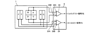
図2に示すように、光検出器7は、第2回折部11で生成された±1次回折光を検出する第1受光部21と、第3、第4回折部12から射出した射出光をそれぞれ検出する第2、第3受光部22、23とから構成される。
第1受光部21は、トラック方向と平行な方向の分割線24と、トラック方向と直交する方向の分割線25とで4等分割された第1〜第4受光領域A〜Dを有している。
As shown in FIG. 2, the
The first
第1〜第8スポット光T1a〜T8bを以下のように定義する。
第1スポット光T1bは、第1回折領域S11で回折された−1次回折光が第1受光領域Aに入射するスポット光であり、第1スポット光T1aは、第1回折領域S11で回折された+1次回折光が第1〜第4受光領域A〜D以外の領域に入射するスポット光である。
第2スポット光T2bは、第2回折領域S12で回折された−1次回折光が第2受光領域Bに入射するスポット光であり、第2スポット光T2bは、第2回折領域S12で回折された+1次回折光が第1〜第4受光領域A〜D以外の領域に入射するスポット光である。
The first to eighth spot lights T1a to T8b are defined as follows.
The first spot light T1b is spot light in which the −1st order diffracted light diffracted in the first diffraction region S11 is incident on the first light receiving region A, and the first spot light T1a is diffracted in the first diffraction region S11. + 1st order diffracted light is spot light that is incident on a region other than the first to fourth light receiving regions A to D.
The second spot light T2b is spot light in which the −1st order diffracted light diffracted in the second diffraction region S12 enters the second light receiving region B, and the second spot light T2b is diffracted in the second diffraction region S12. The first-order diffracted light is spot light that enters a region other than the first to fourth light receiving regions A to D.
第3スポット光T3aは、第3回折領域S21で回折された+1次回折光が第3受光領域Cに入射するスポット光であり、第3スポット光T3bは、第3回折領域S12で回折された−1次回折光が第1〜第4受光領域A〜D以外の領域に入射するスポット光である。
第4スポット光T4aは、第4回折領域S22で回折された+1次回折光が第4受光領域Dに入射するスポット光であり、第4スポット光T4bは、第4回折領域S22で回折された−1次回折光が第1〜第4受光領域以外の領域に入射するスポット光である。
The third spot light T3a is spot light in which the + 1st order diffracted light diffracted in the third diffraction region S21 enters the third light receiving region C, and the third spot light T3b is diffracted in the third diffraction region S12 − The first-order diffracted light is spot light that enters a region other than the first to fourth light receiving regions A to D.
The fourth spot light T4a is spot light in which the + 1st order diffracted light diffracted in the fourth diffraction region S22 enters the fourth light receiving region D, and the fourth spot light T4b is diffracted in the fourth diffraction region S22 − The first-order diffracted light is spot light that enters a region other than the first to fourth light receiving regions.
第5スポット光T5aは、第5回折領域S13で回折された+1次回折光が第3受光領域Cに入射するスポット光であり、第5スポット光T5bは、第5回折領域S13で回折された−1次回折光が第4受光領域Dに入射するスポット光である。
第6スポット光T6aは、第6回折領域S14で回折された+1次回折光が第3受光領域Cに入射するスポット光であり、第6スポット光T6bは、第6回折領域S14で回折された−1次回折光が第4受光領域Dに入射するスポット光である。
The fifth spot light T5a is spot light in which the + 1st order diffracted light diffracted in the fifth diffraction region S13 is incident on the third light receiving region C, and the fifth spot light T5b is diffracted in the fifth diffraction region S13 − The first-order diffracted light is spot light incident on the fourth light receiving region D.
The sixth spot light T6a is spot light in which the + 1st order diffracted light diffracted in the sixth diffraction region S14 is incident on the third light receiving region C, and the sixth spot light T6b is diffracted in the sixth diffraction region S14− The first-order diffracted light is spot light incident on the fourth light receiving region D.
第7スポット光T7aは、第7回折領域S23で回折された+1次回折光が第1受光領域Aに入射するスポット光であり、第7スポット光T7bは、第7回折領域S23で回折された−1次回折光が第2受光領域Bに入射するスポット光である。
第8スポット光T8aは、第4回折領域S24で回折された+1次回折光が第1受光領域Aに入射するスポット光であり、第8スポット光T8bは、第2回折領域S24で回折された−1次回折光が第2受光領域Bに入射するスポット光である。
The seventh spot light T7a is spot light in which the + 1st order diffracted light diffracted in the seventh diffraction region S23 is incident on the first light receiving region A, and the seventh spot light T7b is diffracted in the seventh diffraction region S23 − The first-order diffracted light is spot light incident on the second light receiving region B.
The eighth spot light T8a is spot light in which the + 1st order diffracted light diffracted in the fourth diffraction region S24 is incident on the first light receiving region A, and the eighth spot light T8b is diffracted in the second diffraction region S24− The first-order diffracted light is spot light incident on the second light receiving region B.
従って、各受光領域A〜Dには、以下のようにスポット光が照射される。
第1受光領域Aは、第1スポット光T1b、第7スポットT7a及び第8スポット光T8aを検出する。
第2受光領域Bは、第2スポット光T2b、第7スポット光T7b、第8スポット光T8bを検出する。
Accordingly, the light receiving areas A to D are irradiated with spot light as follows.
The first light receiving region A detects the first spot light T1b, the seventh spot T7a, and the eighth spot light T8a.
The second light receiving region B detects the second spot light T2b, the seventh spot light T7b, and the eighth spot light T8b.
第3受光領域Cは、第3スポット光T3a、第5スポット光T5a、第6スポット光T6aを検出する。
第4受光領域Dは、第4スポット光T4a、第5スポット光T5b、第6スポット光T6bを検出する。
The third light receiving region C detects the third spot light T3a, the fifth spot light T5a, and the sixth spot light T6a.
The fourth light receiving region D detects the fourth spot light T4a, the fifth spot light T5b, and the sixth spot light T6b.
このため、第1回折領域S11及び第2回折領域S12で回折された+1次回折光の第1、第2スポット光T1a,T2a、第3回折領域S21及び第4回折領域S22で回折された−1次回折光の第3、第4スポット光T3b,T4bは、第1〜第4受光領域A〜D以外の領域に入射することになり、第1〜第4受光領域A〜Dでは検出されない。 Therefore, the first and second spot lights T1a and T2a of the + 1st order diffracted light diffracted by the first diffraction region S11 and the second diffraction region S12 are diffracted by the third diffraction region S21 and the fourth diffraction region S22 −. The third and fourth spot lights T3b and T4b of the first-order diffracted light enter the areas other than the first to fourth light receiving areas A to D, and are not detected in the first to fourth light receiving areas A to D.
第2受光部22は、ラジアル方向に平行な分割線26で2等分割された第5、第6受光領域G、Hを有している。
第5受光領域Gは、第2円形回折部12Bから射出された第1射出スポット光U1を検出し、第6受光領域Hは、第1円形回折部12Aから射出された第2射出スポット光U2を検出する。
The second
The fifth light receiving region G detects the first emitted spot light U1 emitted from the second circular diffracting portion 12B, and the sixth light receiving region H is the second emitted spot light U2 emitted from the first circular diffracting
第3受光部23は、ラジアル方向に平行な分割線27で2等分割された第7、第8受光領域I、Jを有している。
第7受光領域Iは、第1円形回折部13Aから射出された第3射出スポット光U3を検出し、第8受光領域Jは、第2円形回折部12Bから射出された第4射出スポットU4光を検出する。
The third
The seventh light receiving region I detects the third emission spot light U3 emitted from the first
上記した第2回折部11の中央部に矩形状開口部14Aが形成されているのは、回折素子6と光検出器7との位置ずれがあった場合に、第1〜第4受光領域A〜Dのそれぞれに入射する第1〜第8スポット光T1b〜T8bの受光面積が等しくならず、検出信号の補正ができなくなるのを防止するためである。
The
また、上記した第3回折部12の第1円形回折部12Aの直径をジャストフォーカスした時の第1回折部10で生成された+1次回折光のスポット径と同じ大きさの径にしているのは、ジャストフォーカスからずれた場合に、第3回折部12の第1円形回折部12Aから射出する第2射出スポット光U2の径が広って、第5受光領域Gで検出されるようにして、フォーカスエラー信号を得るようにしてフォーカスエラー検出を行うためである。
第4回折部13の第1円形回折部13Aの直径をジャストフォーカスした時の第1回折部10で生成された−1次回折光のスポット径と同じ大きさの径にしていることも同様の理由である。従って、第6受光領域Hと第7受光領域Iに第3、第4回折部12、13から射出される第2、第3射出スポット光U2、U3が照射されたときがジャストフォーカス時である。
In addition, the diameter of the first circular diffracting
For the same reason, the diameter of the first circular diffracting
図4に示すように、プッシュプル回路8は、第1オペアンプ28と第2オペアンプ29とからなる。第1オペアンプ28は、光検出器7の第1、第2受光領域A、Bに共通接続された+入力端子28A、第3、第4受光領域C、Dに共通接続された−入力端子28B及び1つの出力端子28Cを有している。第2オペアンプ29は、第6、第7受光領域H、Iに共通接続された+入力端子29A、第5、第8受光領域G、Jに共通接続された−入力端子29B及び1つの出力端子29Cを有している。
As shown in FIG. 4, the push-
次に、トラッキング検出及びフォーカスエラー検出について図5〜図7を用いて詳細に説明する。
まずは、トラッキングエラー信号TEについて図5〜図7を用いて説明する。
図5〜図7中では、第1スポット光T1a、第2スポット光T2a、第3スポット光T3b、第4スポット光T4bを除いた以外の第1〜第12スポット光T1b〜T8bを第1〜第4受光領域A〜Dで得られた信号として扱うことにする。
Next, tracking detection and focus error detection will be described in detail with reference to FIGS.
First, the tracking error signal TE will be described with reference to FIGS.
5 to 7, the first to twelfth spot lights T1b to T8b other than the first spot light T1a, the second spot light T2a, the third spot light T3b, and the fourth spot light T4b are used as the first to twelfth spot lights T1b to T8b. It will be treated as a signal obtained in the fourth light receiving areas A to D.
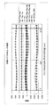
図5〜図7中の横軸は、1トラックピッチでのグルーブQ中心からのレーザスポットずれ量(μm)を示し、縦軸は、各受光領域A〜Dから得られる信号を規格化した値を示している。
ここでは、1トラックピッチは、0.74μmである。
トラッキングエラー信号TE、TE1及び補正信号TE2は、以下の式で示される。
5 to 7, the horizontal axis indicates the laser spot deviation amount (μm) from the center of the groove Q at one track pitch, and the vertical axis indicates a value obtained by standardizing signals obtained from the light receiving areas A to D. Is shown.
Here, one track pitch is 0.74 μm.
The tracking error signals TE and TE1 and the correction signal TE2 are expressed by the following equations.
図5〜図7中、◇は、T1b+T2b、□は、T3a+T4a、+は、TE1、×は、T5a+T5b+T6a+T6b、○は、T7a+T7b+T8a+T8b、*は、補正信号TE2、△は、トラッキングエラー信号TEである。 5 to 7, ◇ is T1b + T2b, □ is T3a + T4a, + is TE1, + is T5a + T5b + T6a + T6b, ○ is T7a + T7b + T8a + T8b, * is a correction signal TE2, and Δ is a tracking error signal TE.
(対物レンズ5のシフト量が0μmである場合)
図2中で対物レンズ5のシフト量が0μm(対物レンズのシフトなし)である場合には、図5に示すように、トラッキングエラー信号は、グルーブQとランドR上では、0で、かつランドRとランドRと隣接するグルーブQとの間では、大きさが等しく正負に対称であり、オフセットは生じていない。
(When the shift amount of the
In FIG. 2, when the shift amount of the
(対物レンズのシフト量が150μmである場合)
図2中で対物レンズ5のシフト量が150μmである場合には、図6に示すように、(対物レンズ5のシフト量が0μmである場合)と同様に、トラッキングエラー信号は、グルーブQとランドR上では0で、かつランドRとランドRに隣接するグルーブQとの間では、大きさが等しく正負に対称であり、オフセットは生じていない。
(When the shift amount of the objective lens is 150 μm)
When the shift amount of the
(対物レンズのシフト量が300μmである場合)
図2中で対物レンズ5のシフト量が300μmであった場合も同様に、図7に示すように、(対物レンズのシフト量が150μmである場合)と同様に、トラッキングエラー信号にオフセットは生じていない。
以上のようにして、対物レンズ5のシフトを生じてもトラッキング検出を行うことができる。また、第1〜第8スポット光T1b〜T8bは、光検出器7の各受光領域A〜Bの分割線24、25上には入射しないので、回折素子6と第1光検出器7との位置合わせにμmオーダーのずれがあった場合でも、トラッキングエラー検出に影響を与えることはない。
(When the shift amount of the objective lens is 300 μm)
Similarly, when the shift amount of the
As described above, tracking detection can be performed even if the
次に、フォーカスエラー信号について図8を用いて説明する。
図8中では、第1〜第4射出スポット光U1〜U4を第5〜第8受光領域G〜Jで得られた信号として扱うことにし、光検出器7の各受光領域G〜Jからは、U1〜U4の信号が得られることを示す。
図7中の横軸は、対物レンズ5がジャストフォーカス位置から光ディスクDに近づく方向への距離(μm)を示し、縦軸は、各受光領域から得られる信号の相対値を示し、○は、U1、◇は、U2、△は、U3、*は、U4、□は、フォーカスエラー信号FEである。
Next, the focus error signal will be described with reference to FIG.
In FIG. 8, the first to fourth emission spot lights U1 to U4 are treated as signals obtained in the fifth to eighth light receiving areas G to J, and the light receiving areas G to J of the
The horizontal axis in FIG. 7 indicates the distance (μm) in the direction in which the
図8に示すように、対物レンズ5がジャストフォーカス位置から光ディスク側に近づいた際のフォーカスエラー信号のカーブは、S字カーブの半分の曲線を示している。
図8では、対物レンズ5がジャストフォーカス位置から光ディスクDに近づく方向に対しての曲線のみを示しているが、遠ざかる方向に対しての曲線は、近づく方向に対しての曲線に対して原点を中心とする点対称の関係を有する。このため、フォーカスエラー信号は、対物レンズ5が光ディスクDに近づく場合と遠ざかる場合を示すS字曲線を描き、このような第5〜第8受光領域で第1〜第4射出スポット光U1〜U4を検出することによりSSD法によるフォーカスエラー検出を行うことができる。
As shown in FIG. 8, the curve of the focus error signal when the
In FIG. 8, only the curve in the direction in which the
次に、その動作について説明する。
半導体レーザ2からレーザ光は、コリメートレンズ3で平行光されて、偏光ビームスプリッタ4に入射する。偏光ビームスプリッタ4に入射した平行光は、偏光分離膜4Aを透過し、対物レンズ5により光ディスクDのトラックに集光する。
この後、光ディスクDに集光されたレーザ光は、トラックで反射されて円形状の反射光を生じる。この反射光は、偏光ビームスプリッタ4に入射し、偏光分離膜4Aで反射され、回折素子6に入射する。
Next, the operation will be described.
Laser light from the semiconductor laser 2 is collimated by the
Thereafter, the laser light focused on the optical disk D is reflected by the track to generate circular reflected light. The reflected light enters the polarization beam splitter 4, is reflected by the
回折素子6の第1回折部10で円形状の0次光と±1次回折光が生成され、0次光は、第2回折部11に、+1次回折光は、第3回折部12に、−1次回折光は、第4回折部13に入射する。
このとき、第1回折部10には、上記したように±1次回折光のうちの一方を他方の面9Bの手前で焦点を結び、他方を他方の面9Bの後方で焦点を結ぶように回折領域が形成されているので、SSD法によるフォーカスエラー検出を行うことができる。
The first
At this time, the first diffracting
第2回折部11に入射した0次光の中には、反射光L1、L2、L3が含まれる。
第2回折部11の第1〜第8回折領域S11〜S14、S21〜S24には、第1反射光L1が入射し、第1、第2回折領域S11、S12には、反射光L2が入射し、第3、第4回折領域S21、S22には、反射光L3が入射する。
The 0th-order light incident on the second
The first reflected light L1 is incident on the first to eighth diffraction regions S11 to S14 and S21 to S24 of the second
第2回折部11の第1回折領域S11で回折された第1スポット光T1b及び第7回折領域S23及び第8回折領域S24で回折された+1次回折光をそれぞれ第7、第8スポット光T7a、T8aは、第1受光領域Aに入射する。
第2回折領域S12及び第7回折領域S23及び第8回折領域S24で回折された第2スポット光T2b、第7、第8スポット光T7b、T8bは、第2受光領域Bに入射する。
The first spot light T1b diffracted by the first diffraction region S11 of the
The second spot light T2b, the seventh spot light T7b, and the eighth spot light T7b diffracted by the second diffraction area S12, the seventh diffraction area S23, and the eighth diffraction area S24 are incident on the second light receiving area B.
第3回折領域S21、第5回折領域S13及び第6回折領域S14で回折された第3スポット光T3a、第5、第6スポット光T5a、T6aは、第3受光領域Cに入射する。
第4回折領域S22で回折された第4スポット光T4a及び第5回折領域S13及び第6回折領域S14で回折された第5、第6スポット光T5b、T6bは、第4受光領域Dに入射する。
The third spot light T3a, the fifth and sixth spot lights T5a, T6a diffracted by the third diffraction region S21, the fifth diffraction region S13, and the sixth diffraction region S14 are incident on the third light receiving region C.
The fourth spot light T4a diffracted by the fourth diffraction region S22 and the fifth and sixth spot light T5b, T6b diffracted by the fifth diffraction region S13 and the sixth diffraction region S14 enter the fourth light receiving region D. .
第3回折部12の第2円形回折部12Bから射出された第1射出スポット光U1は、第5受光領域Gに入射する。第1円形回折部12Aから射出された第2射出スポット光U2は、第6受光領域Hに入射する。
第4回折部13の第1円形回折部13Aから射出された第3射出スポット光U3は、第7受光領域Iに入射する。第2円形回折部12Bから射出された第4射出スポット光U4は、第8受光領域Jに入射する。
The first exit spot light U1 emitted from the second circular diffraction unit 12B of the
The third exit spot light U3 emitted from the first
第1、第2受光領域A、Bで光電変換された第1スポット光T1b、第2スポット光T2b、第7スポット光T7a,T7b、第8スポット光T8a,T8bを加算した信号を第1オペアンプ28の+入力端子28Aに入力し、第3、第4受光領域C、Dで光電変換された第3スポット光T3a、第4スポット光T4a、第5スポット光T5a,T5b、第6スポット光T6a,T6bを加算した信号を−入力端子28Bに入力して、その差を演算して出力端子28Cから出力してトラッキングエラー信号を得る。 A signal obtained by adding the first spot light T1b, the second spot light T2b, the seventh spot lights T7a and T7b, and the eighth spot lights T8a and T8b photoelectrically converted in the first and second light receiving regions A and B is a first operational amplifier. The third spot light T3a, the fourth spot light T4a, the fifth spot lights T5a and T5b, and the sixth spot light T6a photoelectrically converted in the third and fourth light receiving regions C and D. , T6b are added to the negative input terminal 28B, the difference is calculated and output from the output terminal 28C to obtain a tracking error signal.
第6、第7受光領域H、Iで光電変換された第1、第2射出スポット光U2、U3を加算した信号を第2オペアンプ29の+入力端子29Aに入力し、第5、第8受光領域G、Jで光電変換された第3、第4スポット光U1、U4を加算した信号を−入力端子29Bに入力して、その差を演算して出力端子29Cから出力してフォーカスエラー信号を得る。
A signal obtained by adding the first and second emission spot lights U2 and U3 photoelectrically converted in the sixth and seventh light receiving regions H and I is input to the + input terminal 29A of the second
以上のように、本発明の実施例によれば、第1回折部10は、光ディスクDの反射光から生成した円形状の±1次回折光のうちの一方を他方の面9Bの手前で焦点を結び、他方を他方の面9Bの後方で焦点を結ぶように回折領域が形成され、第2回折部11は、中央部に矩形状開口部14Aを有した正方形状の回折領域14からなるので、対物レンズ5のシフトや回折素子6と光検出器7との位置合わせずれを生じても、正確なトラッキングエラー検出を行うことができ、かつSSD法によるフォーカスエラー検出を行うことができる。また、3ビーム法を用いて、HD−DVD(High Density Digital Versatile Disc)とBD(Blu Ray Disc)を1台のピックアップで記録再生する場合には、2つの対物レンズが必要となる。この場合、2つの対物レンズに対してオフセンター調整を行う必要がある。この点、本発明の実施例のように1ビームで行う場合には、オフセンター調整を行う必要がない。
As described above, according to the embodiment of the present invention, the first diffracting
なお、実施例では、第2回折部11には矩形状開口部14Aを有するようにしたが、円形状の開口部でも多角形状の開口部でも良い。また、第1〜第4回折領域S11〜S14を正方形、S21〜S24を長方形としたが、多角形状でも良い。第2円形回折部12B、13Bは、円形に限らず多角形状や楕円形状でも良い。実施例では、トラックをグルーブQとしたが、ランドRにしても同様である。
In the embodiment, the second
1…光ピックアップ装置、2…半導体レーザ、3…コリメートレンズ、4…偏光ビームスプリッタ、4A…偏光分離膜、5…対物レンズ、6…回折素子、7…光検出器、8…プッシュプル回路、9…光透過性基板、9A…一方の面、9B…他方の面、10…第1回折部、11…第2回折部、12…第3回折部、13…第4回折部、12A、13A…第1円形回折部、12A、13B…第2円形回折部、14…回折領域、14A…矩形状開口部、15…第1分割線、16…第2分割線、17…第3分割線、18…第4分割線、19…第5分割線、20…第6分割線、21…第1受光部、22…第2受光部、23…第3受光部、24、25、26、27…分割線、28…第1オペアンプ、29…第2オペアンプ、S11…第1回折領域、S12…第2回折領域、S21…第3回折領域、S22…第4回折領域、S13…第5回折領域、S14…第6回折領域、S23…第7回折領域、S24…第8回折領域、L1、L2、L3…反射光、A…第1受光領域、B…第2受光領域、C…第3受光領域、D…第4受光領域、G…第5受光領域、H…第6受光領域、I…第7受光領域、J…第8受光領域
DESCRIPTION OF SYMBOLS 1 ... Optical pick-up apparatus, 2 ... Semiconductor laser, 3 ... Collimating lens, 4 ... Polarization beam splitter, 4A ... Polarization separation film, 5 ... Objective lens, 6 ... Diffraction element, 7 ... Photo detector, 8 ... Push-pull circuit, DESCRIPTION OF
Claims (4)
前記回折素子は、
光透過性基板の一方の面に形成され、前記反射光を回折して0次光及び±1次回折光を生成する第1回折部と、
前記光透過性基板の他方の面に形成された回折領域を有し、かつ前記第1回折部で生成された前記0次光を回折する第2回折部と、
前記第1回折部で生成された前記±1次回折光を分岐する第3、第4回折部と、を備え、
前記第2回折部の回折領域は、第1〜第8回折領域からなり、前記回折領域を前記光ディスクのトラック方向と平行に2等分割する分割線を第1分割線、前記トラック方向に平行で、かつ前記第1分割線から等距離に形成された分割線を第2、第3分割線、前記光ディスクのラジアル方向と平行に2等分割する分割線を第4分割線、前記ラジアル方向に平行で、かつ第4分割線から等距離に形成された分割線を第5、第6分割線とするとき、
前記第1回折領域は、前記第2分割線、前記第4分割線、前記第5分割線及び前記回折領域の外周縁で囲まれた領域、前記第2回折領域は、前記第2分割線、前記第4分割線、前記第6分割線及び前記回折領域の外周縁で囲まれた領域、前記第3回折領域は、前記第3分割線、前記第4分割線、前記第5分割線及び前記回折領域の外周縁で囲まれた領域、第4回折領域は、前記第3分割線、前記第4分割線、前記第6分割線及び前記回折領域の外周縁で囲まれた領域、前記第5回折領域は、前記第1分割線、前記第5分割線、前記回折領域の外周縁で囲まれた第1領域、前記第6回折領域は、前記第1分割線、前記第6分割線、前記回折領域の外周縁で囲まれた第3領域、前記第7回折領域は、前記第1分割線、前記第5分割線及び前記回折領域の外周縁で囲まれた第2領域、前記第8回折領域は、前記第1分割線、前記第6分割線及び前記回折領域の外周縁で囲まれた第4領域であり、
前記光検出器は、
前記第1回折領域で回折された−1次回折光及び前記第7、第8回折領域で回折された+1次回折光を検出する第1受光領域と、
前記第2回折領域、前記第7回折領域及び前記第8回折領域で回折された−1次回折光を検出する第2受光領域と、
前記第3回折領域、前記第5、第6回折領域で回折された+1次回折光を検出する第3受光領域と、
前記第4回折領域で回折された+1次回折光及び前記第5、第6回折領域で回折された−1次回折光を検出する第4受光領域と、
前記第3、第4回折部で分岐された分岐光を検出する第2、第3受光部と、を備えたことを特徴とする光ピックアップ装置。 An objective lens that condenses the laser light on the track of the optical disc, a diffraction element that generates diffracted light from the reflected light reflected by the track, and a plurality of light receiving regions. The diffracted light is received and photoelectrically converted. In an optical pickup device comprising a photodetector, and performing tracking error detection and focus error detection using a signal photoelectrically converted in each light receiving region,
The diffraction element is
A first diffractive portion that is formed on one surface of the light-transmitting substrate and diffracts the reflected light to generate 0th order light and ± 1st order diffracted light;
A second diffractive portion having a diffractive region formed on the other surface of the light transmissive substrate and diffracting the zero-order light generated by the first diffractive portion;
A third and a fourth diffracting section for branching the ± first-order diffracted light generated by the first diffracting section,
The diffraction region of the second diffractive portion includes first to eighth diffraction regions, and a dividing line that divides the diffraction region into two equal parts parallel to the track direction of the optical disc is defined as a first dividing line and parallel to the track direction. The dividing lines formed at the same distance from the first dividing line are the second and third dividing lines, the dividing line that bisects the optical disk in parallel with the radial direction of the optical disc is the fourth dividing line, and is parallel to the radial direction. And when the dividing lines formed equidistant from the fourth dividing line are the fifth and sixth dividing lines,
The first diffraction region is a region surrounded by the second dividing line, the fourth dividing line, the fifth dividing line, and an outer periphery of the diffraction region, and the second diffraction region is the second dividing line, The fourth dividing line, the sixth dividing line, the region surrounded by the outer periphery of the diffraction region, the third diffraction region includes the third dividing line, the fourth dividing line, the fifth dividing line, and the The region surrounded by the outer periphery of the diffraction region, the fourth diffraction region, the third dividing line, the fourth dividing line, the sixth dividing line, and the region surrounded by the outer periphery of the diffraction region, the fifth The diffraction area is the first dividing line, the fifth dividing line, the first area surrounded by the outer periphery of the diffraction area, the sixth diffraction area is the first dividing line, the sixth dividing line, the The third region surrounded by the outer periphery of the diffraction region, the seventh diffraction region, the first dividing line, the fifth dividing line, and the diffraction The second region, the eighth diffractive region surrounded by the outer peripheral edge of the band, the first dividing line, a fourth region surrounded by the outer peripheral edge of said sixth dividing line and the diffraction region,
The photodetector is
A first light receiving region for detecting −1st order diffracted light diffracted in the first diffraction region and + 1st order diffracted light diffracted in the seventh and eighth diffraction regions;
A second light receiving region for detecting −1st order diffracted light diffracted in the second diffraction region, the seventh diffraction region, and the eighth diffraction region;
A third light receiving region for detecting + 1st order diffracted light diffracted in the third diffraction region, the fifth and sixth diffraction regions,
A fourth light receiving region for detecting + 1st order diffracted light diffracted in the fourth diffraction region and -1st order diffracted light diffracted in the fifth and sixth diffraction regions;
An optical pickup device comprising: second and third light receiving parts for detecting branched light branched by the third and fourth diffraction parts.
The first diffracting unit condenses one of ± first-order diffracted lights generated from the reflected light of the optical disc before the third diffracting unit or the fourth diffracting unit, and the other is the third diffracting unit or 4. The optical pickup device according to claim 1, further comprising a diffraction region that is focused on the photodetector side of the fourth diffraction section. 5.
Priority Applications (1)
| Application Number | Priority Date | Filing Date | Title |
|---|---|---|---|
| JP2005340183A JP2007149190A (en) | 2005-11-25 | 2005-11-25 | Optical pickup device |
Applications Claiming Priority (1)
| Application Number | Priority Date | Filing Date | Title |
|---|---|---|---|
| JP2005340183A JP2007149190A (en) | 2005-11-25 | 2005-11-25 | Optical pickup device |
Publications (1)
| Publication Number | Publication Date |
|---|---|
| JP2007149190A true JP2007149190A (en) | 2007-06-14 |
Family
ID=38210442
Family Applications (1)
| Application Number | Title | Priority Date | Filing Date |
|---|---|---|---|
| JP2005340183A Pending JP2007149190A (en) | 2005-11-25 | 2005-11-25 | Optical pickup device |
Country Status (1)
| Country | Link |
|---|---|
| JP (1) | JP2007149190A (en) |
Cited By (1)
| Publication number | Priority date | Publication date | Assignee | Title |
|---|---|---|---|---|
| WO2010131461A1 (en) * | 2009-05-15 | 2010-11-18 | パナソニック株式会社 | Optical head apparatus, light receiving element, integrated circuit, photonic integrated element, optical disc apparatus, and signal detection method |
-
2005
- 2005-11-25 JP JP2005340183A patent/JP2007149190A/en active Pending
Cited By (1)
| Publication number | Priority date | Publication date | Assignee | Title |
|---|---|---|---|---|
| WO2010131461A1 (en) * | 2009-05-15 | 2010-11-18 | パナソニック株式会社 | Optical head apparatus, light receiving element, integrated circuit, photonic integrated element, optical disc apparatus, and signal detection method |
Similar Documents
| Publication | Publication Date | Title |
|---|---|---|
| KR100831138B1 (en) | Apparatus for optically recording and reproducing information | |
| US8045432B2 (en) | Optical disc device | |
| JP2008027563A (en) | Optical pickup device | |
| JP2975395B2 (en) | Optical pickup device | |
| KR20100032824A (en) | Optical pickup apparatus | |
| JP2002208170A (en) | Optical pickup device capable of detecting change in thickness of recording medium and/or correcting spherical aberration caused by change in thickness | |
| JPH05307759A (en) | Optical pickup | |
| JP2007149190A (en) | Optical pickup device | |
| US20030218949A1 (en) | Method for detecting radial tilt of optical recording medium in optical head device, optical head device, and optical information recording/reproducing device | |
| KR100600297B1 (en) | Optical pick-up equipment for optical disk having a different track pitch | |
| US8189435B2 (en) | Spherical aberration detecting device and an optical pickup device including same | |
| JP2012113767A (en) | Optical pickup device and optical information recording and reproducing device having the same | |
| JP2009181670A (en) | Optical head device and optical disk device | |
| JP2010211859A (en) | Optical pickup device | |
| JP2012108985A (en) | Optical pickup | |
| US6335809B1 (en) | Optical pickup and hologram device | |
| WO2010131406A1 (en) | Optical head device, hologram element, optical integrated element, optical information processing device and signal detection method | |
| JP2004178771A (en) | Servo device and device for recording and reproducing optical disk information | |
| US8867325B2 (en) | Optical pickup apparatus having diffractive element for focusing and tracking plurality of light types | |
| US8045428B2 (en) | Optical pickup apparatus | |
| JP2006079785A (en) | Optical pickup device and optical disk device | |
| JP2648140B2 (en) | Optical head device | |
| JP2002216368A (en) | Optical pickup device and optical disk apparatus | |
| US7622696B2 (en) | Optical head device, optical information recording/reproducing apparatus and operation method of optical information recording/reproducing apparatus | |
| JP2006059452A (en) | Optical pickup device |