JP2007148564A - Card reader controller - Google Patents
Card reader controller Download PDFInfo
- Publication number
- JP2007148564A JP2007148564A JP2005339168A JP2005339168A JP2007148564A JP 2007148564 A JP2007148564 A JP 2007148564A JP 2005339168 A JP2005339168 A JP 2005339168A JP 2005339168 A JP2005339168 A JP 2005339168A JP 2007148564 A JP2007148564 A JP 2007148564A
- Authority
- JP
- Japan
- Prior art keywords
- card reader
- card
- communication quality
- communication
- transmission power
- Prior art date
- Legal status (The legal status is an assumption and is not a legal conclusion. Google has not performed a legal analysis and makes no representation as to the accuracy of the status listed.)
- Granted
Links
- 238000004891 communication Methods 0.000 claims abstract description 167
- 230000005540 biological transmission Effects 0.000 claims abstract description 138
- 238000001514 detection method Methods 0.000 claims abstract description 70
- 238000000034 method Methods 0.000 claims description 24
- 230000008859 change Effects 0.000 claims description 19
- 230000007423 decrease Effects 0.000 claims description 6
- 238000012545 processing Methods 0.000 description 18
- 238000010586 diagram Methods 0.000 description 17
- 230000001965 increasing effect Effects 0.000 description 14
- 230000008569 process Effects 0.000 description 14
- 238000012423 maintenance Methods 0.000 description 5
- 230000001939 inductive effect Effects 0.000 description 4
- 238000010248 power generation Methods 0.000 description 4
- 239000000284 extract Substances 0.000 description 3
- 230000006870 function Effects 0.000 description 3
- 230000033228 biological regulation Effects 0.000 description 2
- 230000001276 controlling effect Effects 0.000 description 2
- 238000012790 confirmation Methods 0.000 description 1
- 230000003247 decreasing effect Effects 0.000 description 1
- 238000001914 filtration Methods 0.000 description 1
- 230000002452 interceptive effect Effects 0.000 description 1
- 230000007246 mechanism Effects 0.000 description 1
- 230000001105 regulatory effect Effects 0.000 description 1
- 230000004044 response Effects 0.000 description 1
- 239000013589 supplement Substances 0.000 description 1
Images

Landscapes
- Near-Field Transmission Systems (AREA)
Abstract
Description
本発明は、電波を用いて非接触にてカードと通信を行うカードリーダの調整などを行うカードリーダ制御装置に関する。 The present invention relates to a card reader control device that adjusts a card reader that communicates with a card in a non-contact manner using radio waves.
現在、非接触式のICカードリーダとICカードとして、変調方式や符号化の種類など通信条件が異なる様々なタイプの組み合わせが提供されている。しかしながら、変調方式や符号化の種類など通信条件が異なることから、ICカードリーダは全種類のICカードと通信を行うことができない。
例えば、テナントビルにおいて、テナントビルの出入り口付近にICカードリーダを設置し、ICカードに記録されたデータを読み取ることにより人の出入りを監視することがある。この場合、入居するテナント毎に異なる通信条件のカードを採用することがあり、上述した理由からテナントによって採用された各ICカードに対応したICカードリーダを用意しなければならない。このとき、テナントビルの入居者が自身のICカードに対応するICカードリーダがどれかを考えてICカードをかざさなくてもすむように、各ICカードリーダが備えるアンテナを近接して設置して入居者がICカードの種類にかかわらずほぼ同じ位置にICカードをかざせばよいようにすることが考えられる。
Currently, various types of combinations with different communication conditions, such as modulation schemes and types of encoding, are provided as contactless IC card readers and IC cards. However, the IC card reader cannot communicate with all types of IC cards because the communication conditions such as the modulation method and the type of encoding are different.
For example, in a tenant building, an IC card reader may be installed near the entrance and exit of the tenant building, and the entry and exit of a person may be monitored by reading data recorded on the IC card. In this case, a card with different communication conditions may be adopted for each tenant occupying, and an IC card reader corresponding to each IC card adopted by the tenant must be prepared for the reason described above. At this time, the tenant building occupants are placed in close proximity to the antennas of each IC card reader so that they do not have to hold the IC card in consideration of which IC card reader corresponds to their IC card. It is conceivable that a person can hold the IC card at almost the same position regardless of the type of IC card.
ところが、複数のICカードリーダを近接して設置する場合、ICカードリーダとICカードとの間の通信が別のICカードリーダが出力する電波による影響を受け、ICカードリーダがICカードに記録されているデータを正しく読み出すことができない場合が生じる。
これを解決する技術として次のようなものが知られている。ICカードリーダが他のICカードリーダから干渉を受けてICカードからデータを読み出すことができない場合に、ICカードリーダが出力する搬送波の周波数を変更する。これにより、信号成分を含む側波帯の周波数領域を移動させ、他のカードリーダが出力する電波による影響を低減する(例えば、特許文献1参照。)。
The following techniques are known to solve this problem. When the IC card reader is unable to read data from the IC card due to interference from other IC card readers, the frequency of the carrier wave output from the IC card reader is changed. Thereby, the frequency region of the sideband including the signal component is moved, and the influence of the radio wave output from another card reader is reduced (see, for example, Patent Document 1).
ところが、上記の従来の仕組みは、ICカードリーダが複数の周波数の搬送波を出力することができることを必要とすることから、搬送波の周波数を変更することができないICカードリーダ間での電波の干渉を回避する場合には適用することができない。
そこで、本発明は、カードリーダが他のカードリーダから干渉を受けてカードと通信ができなくなるような状況を搬送波の周波数を変更することなく回避することができるカードリーダ制御装置を提供することを目的とする。
However, the above-described conventional mechanism requires that the IC card reader can output a carrier wave having a plurality of frequencies, so that the radio wave interference between IC card readers that cannot change the frequency of the carrier wave is reduced. It cannot be applied to avoid it.
Therefore, the present invention provides a card reader control device capable of avoiding a situation in which a card reader cannot communicate with a card due to interference from another card reader without changing the frequency of the carrier wave. Objective.
上記目的を達成するために本発明のカードリーダ制御装置は、電波を用いて非接触にてカードと行う通信の通信条件が互いに異なり、相互に干渉し得る位置に配されている複数のカードリーダの調整を行うカードリーダ制御装置において、複数の前記カードリーダの中から1つのカードリーダの指定を受け付ける受付手段と、前記受付手段により受け付けた前記カードリーダと当該カードリーダのカード読み取り範囲に存在するカードとの間で行われる通信の通信品質を検出する検出手段と、前記検出手段により検出される前記通信品質が予め定められた通信品質以下であるか否かを判断する判断手段と、前記判断手段により前記通信品質が予め定められた通信品質以下であると判断される場合に、前記受付手段により受け付けたカードリーダ以外のカードリーダの送信電力が検出時より低下するように、又は、前記受付手段により受け付けたカードリーダの送信電力が検出時より大きくなるように、送信電力の設定を行う電力設定手段と、を備えたことを特徴とする。 In order to achieve the above object, a card reader control device according to the present invention has a plurality of card readers arranged in positions where communication conditions for communication with a card in a contactless manner using radio waves are different from each other and can interfere with each other. In the card reader control device that performs the adjustment, the receiving unit that receives designation of one card reader from among the plurality of card readers, the card reader received by the receiving unit, and the card reading range of the card reader Detecting means for detecting communication quality of communication performed with the card; determining means for determining whether the communication quality detected by the detecting means is equal to or lower than a predetermined communication quality; and If the communication quality is determined to be equal to or lower than a predetermined communication quality by the means, the card reader received by the reception means Power setting means for setting the transmission power so that the transmission power of the card reader other than is lower than that at the time of detection, or so that the transmission power of the card reader received by the receiving means is larger than that at the time of detection, It is characterized by having.
上記のカードリーダ制御装置によれば、指定されたカードリーダとカードとの間で行われる通信の通信品質が予め定められた通信品質以下であれば、指定されたカードリーダからみてノイズ源となるカードリーダの送信電力を低下させ、指定されたカードリーダが受信するノイズの電力レベルが低くなるようにしている。或いは、指定されたカードリーダの送信電力を大きくして、指定されたカードリーダが受信する信号の電力レベルが大きくなるようにしている。このため、搬送波の周波数を変更することなく、カードリーダが他のカードリーダから干渉を受けてカードと通信ができなくなるような状況を回避できるようになる。 According to the above card reader control device, if the communication quality of communication performed between the designated card reader and the card is equal to or lower than the predetermined communication quality, it becomes a noise source as seen from the designated card reader. The transmission power of the card reader is lowered so that the power level of noise received by the designated card reader is lowered. Alternatively, the transmission power of the designated card reader is increased so that the power level of the signal received by the designated card reader is increased. For this reason, it becomes possible to avoid a situation in which the card reader is unable to communicate with the card due to interference from other card readers without changing the frequency of the carrier wave.
また、本発明のカードリーダ制御装置は、電波を用いて非接触にてカードと行う通信の通信条件が互いに異なり、相互に干渉し得る位置に配されている複数のカードリーダの調整を行うカードリーダ制御装置において、複数の前記カードリーダの中から1つのカードリーダの指定を受け付ける受付手段と、前記受付手段により受け付けた前記カードリーダと当該カードリーダのカード読み取り範囲に存在するカードとの間で行われる通信の通信品質を検出する検出手段と、前記検出手段により検出される前記通信品質が予め定められた通信品質以下であるか否かを判断する判断手段と、前記判断手段により前記通信品質が予め定められた通信品質以下であると判断される場合に、前記受付手段により受け付けたカードリーダが行う送信データを切り替える変調速度を検出時の変調速度と異なるように変更して変調速度の設定を行う変調速度設定手段と、を備えたことを特徴とする。なお、変調速度とは、送信データを送信するシンボルレートであり、変調速度は単位時間当たりのシンボルの切り替え回数によって変化する。また、シンボルとは、1回の変調で送信する1ビットあるいは複数ビットのデータである。 The card reader control device of the present invention is a card that adjusts a plurality of card readers arranged at positions where communication conditions for communication with a card using radio waves are different from each other and can interfere with each other. In the reader control device, a receiving unit that receives designation of one card reader from among the plurality of card readers, and the card reader received by the receiving unit and a card existing in the card reading range of the card reader. Detecting means for detecting the communication quality of the communication to be performed; determining means for determining whether the communication quality detected by the detecting means is equal to or lower than a predetermined communication quality; and determining the communication quality by the determining means Data transmitted by the card reader received by the receiving means when it is determined that is less than or equal to a predetermined communication quality A modulation rate setting means for modulating the speed of change to be different from the time of detecting modulation rate to set the modulation speed of switching, characterized by comprising a. The modulation rate is a symbol rate at which transmission data is transmitted, and the modulation rate changes depending on the number of symbol switching per unit time. A symbol is 1-bit or multiple-bit data transmitted by one modulation.
上記のカードリーダ制御装置によれば、指定されたカードリーダとカードとの間で行われる通信の通信品質が予め定められた通信品質以下であれば、指定されたカードリーダの変調速度を変更する。この変調速度の変更によって、例えば、側波帯の周波数領域がノイズ源となるカードリーダが出力する電波の電力レベルが低い周波数領域に移動すれば、指定されたカードリーダにおいて信号成分を含む側波帯の周波数領域でのノイズの電力レベルが低下する。このため、搬送波の周波数を変更することなく、カードリーダが他のカードリーダから干渉を受けてカードと通信ができなくなるような状況を回避できるようになる。 According to the above card reader control device, the modulation rate of the designated card reader is changed if the communication quality of communication performed between the designated card reader and the card is equal to or lower than the predetermined communication quality. . By changing the modulation speed, for example, if the frequency region of the sideband moves to a frequency region where the power level of the radio wave output from the card reader serving as the noise source is low, the sideband including the signal component in the designated card reader is used. The noise power level in the band frequency range is reduced. For this reason, it becomes possible to avoid a situation in which the card reader is unable to communicate with the card due to interference from other card readers without changing the frequency of the carrier wave.
また、上記のカードリーダ制御装置において、前記変調速度設定手段は変調速度の変更を変調速度を遅くすることにより行い、前記変調速度設定手段による変更後の変調速度に応じて、前記受付手段により受け付けたカードリーダの送信電力が検出時より大きくなるように送信電力の設定を行う電力設定手段を更に備えることとしてもよい。
これによれば、変調速度を遅くして指定されたカードリーダの側波帯の周波数領域を移動させながら、指定されたカードリーダの送信電力を大きくして受信信号の電力レベルが大きくなるようにしている。このため、カードリーダが他のカードリーダから干渉を受けてカードと通信ができなくなるような状況をより確実に回避できるようになる。
In the above card reader control device, the modulation speed setting means changes the modulation speed by slowing down the modulation speed, and the reception means accepts the modulation speed according to the modulation speed after the change by the modulation speed setting means. It is also possible to further include power setting means for setting the transmission power so that the transmission power of the card reader is larger than that at the time of detection.
According to this, the power level of the received signal is increased by increasing the transmission power of the designated card reader while moving the frequency region of the designated side band of the card reader by reducing the modulation speed. ing. For this reason, it is possible to more reliably avoid a situation in which the card reader cannot communicate with the card due to interference from other card readers.
なお、現在、電波法では誘導式読み書き通信設備に関して、変調速度に対して側波帯の電力レベルの上限が定められており、変調速度が遅くなるにつれて側波帯の電力レベルの上限が段階的に大きくなるように定められている。上記構成は電波法の誘導式読み書き通信設備に関する規制に沿ったものにもなっている。
また、本発明のカードリーダ制御装置は、電波を用いて非接触にてカードと行う通信の通信条件が互いに異なり、相互に干渉し得る位置に配されている複数のカードリーダの調整を行うカードリーダ制御装置において、複数の前記カードリーダの中から1つのカードリーダの指定を受け付ける受付手段と、前記受付手段により受け付けた前記カードリーダと当該カードリーダのカード読み取り範囲に存在するカードとの間で行われる通信の通信品質を検出する検出手段と、前記検出手段により検出される前記通信品質が予め定められた通信品質以下であるか否かを判断する判断手段と、前記判断手段により前記通信品質が予め定められた通信品質以下であると判断される場合に、前記受付手段により受け付けたカードリーダが電波を出力する出力タイミングを検出時の出力タイミングと異なるように変更して出力タイミングの設定を行うタイミング設定手段と、を備えたことを特徴とする。
Currently, the inductive read / write communication equipment has an upper limit on the sideband power level with respect to the modulation speed, and the upper limit of the sideband power level gradually decreases as the modulation speed decreases. It is determined to be larger. The above configuration is also in line with regulations concerning inductive read / write communication facilities of the Radio Law.
The card reader control device of the present invention is a card that adjusts a plurality of card readers arranged at positions where communication conditions for communication with a card using radio waves are different from each other and can interfere with each other. In the reader control device, a receiving unit that receives designation of one card reader from among the plurality of card readers, and the card reader received by the receiving unit and a card existing in the card reading range of the card reader. Detecting means for detecting the communication quality of the communication to be performed; determining means for determining whether the communication quality detected by the detecting means is equal to or lower than a predetermined communication quality; and determining the communication quality by the determining means Is determined to be below a predetermined communication quality, the card reader received by the receiving means outputs radio waves. And timing setting means to change the force timing to be different from the output timing for the detection to set the output timing, characterized by comprising a.
上記のカードリーダ制御装置によれば、指定されたカードリーダとカードとの間で行われる通信の通信品質が予め定められた通信品質以下であれば、指定されたカードリーダが電波を出力する出力タイミングを変更して、指定されたカードリーダからみてノイズ源となるカードリーダの出力タイミングとずれるようにする。このため、搬送波の周波数を変更することなく、カードリーダが他のカードリーダから干渉を受けてカードと通信ができなくなるような状況を回避できるようになる。 According to the above card reader control device, if the communication quality of communication performed between the specified card reader and the card is equal to or lower than the predetermined communication quality, the output from which the specified card reader outputs radio waves. The timing is changed so that it deviates from the output timing of the card reader that becomes a noise source when viewed from the designated card reader. For this reason, it becomes possible to avoid a situation in which the card reader is unable to communicate with the card due to interference from other card readers without changing the frequency of the carrier wave.
また、上記のカードリーダ制御装置の夫々において、前記検出手段は前記通信品質の検出を通信品質に関連した指標である誤り率を算出することにより行い、前記判断手段は前記誤り率が予め定められた閾値を超えた場合に前記通信品質が予め定められた通信品質以下であると判断することとしてもよい。これにより、通信品質が予め定められた通信品質以下であるか否かの判断を行う一形態を実現できる。 Further, in each of the above card reader control devices, the detection means detects the communication quality by calculating an error rate that is an index related to communication quality, and the determination means determines the error rate in advance. It may be determined that the communication quality is equal to or lower than a predetermined communication quality when the threshold value is exceeded. Thereby, the form which determines whether communication quality is below the communication quality defined beforehand is realizable.
また、本発明のカードリーダ制御装置は、電波を用いて非接触にてカードと行う通信の通信条件が互いに異なり、相互に干渉し得る位置に配されている複数のカードリーダの制御を行うカードリーダ制御装置において、複数の前記カードリーダの中からカードと通信しているカードリーダを検知する検知手段と、前記検知手段により検知される前記カードリーダ以外のカードリーダの送信電力が低下するように送信電力の制御を行う電力制御手段と、を備えたことを特徴とする。なお、「通信している」とは、カードリーダとカードとの間で例えば通信リンクが確立した段階など予め定められた段階まで通信が進んだことを意味する。 Further, the card reader control device of the present invention is a card that controls a plurality of card readers arranged at positions where communication conditions for communication with a card in a contactless manner using radio waves are different from each other and can interfere with each other. In the reader control device, a detection means for detecting a card reader communicating with a card from among the plurality of card readers, and a transmission power of a card reader other than the card reader detected by the detection means is reduced. And power control means for controlling transmission power. Note that “communicating” means that communication has progressed to a predetermined stage, for example, a stage at which a communication link is established between the card reader and the card.
上記のカードリーダ制御装置によれば、複数のカードリーダの中の1つのカードリーダがカードと通信を開始すれば、通信を開始したカードリーダからみてノイズ源となるそれ以外のカードリーダの送信電力が低くなるようにして、指定されたカードリーダが受信するノイズの電力レベルを低くする。このため、搬送波の周波数を変更することなく、カードリーダが他のカードリーダから干渉を受けてカードと通信ができなくなるような状況を回避できるようになる。 According to the above card reader control device, if one of the plurality of card readers starts communication with the card, the transmission power of other card readers that become noise sources as seen from the card reader that started communication The power level of noise received by the designated card reader is lowered. For this reason, it becomes possible to avoid a situation in which the card reader is unable to communicate with the card due to interference from other card readers without changing the frequency of the carrier wave.
《第1の実施の形態》
以下、本発明の第1の実施の形態におけるカードリーダ制御装置について図面を参照しつつ説明する。なお、第1の実施の形態におけるカードリーダ制御装置は、複数のカードリーダの導入時やメンテナンス時などに、カードリーダが他のカードリーダから干渉を受けてカードと行う通信の通信品質が予め定められた通信品質以下にならないように、カードリーダの送信電力を調整するものである。ただし、カードリーダの送信電力のレベルは搬送波の出力電力のレベルを指し、他においても同様である。
<全体構成>
本発明の第1の実施の形態におけるカードリーダ制御装置を含むシステム全体の構成について図1および図2を参照しつつ説明する。図1は本実施の形態におけるカードリーダ制御装置を含むシステム全体の構成を示すシステム構成図である。図2は図1の各非接触式のICカードリーダのアンテナコイルが配される位置関係を示す模式図である。
<< First Embodiment >>
Hereinafter, a card reader control device according to a first embodiment of the present invention will be described with reference to the drawings. Note that the card reader control device according to the first embodiment determines in advance the communication quality of the communication that the card reader performs with the card due to interference from other card readers when a plurality of card readers are introduced or during maintenance. The transmission power of the card reader is adjusted so that the communication quality does not fall below the specified communication quality. However, the level of transmission power of the card reader indicates the level of output power of the carrier wave, and the same applies to other cases.
<Overall configuration>
The configuration of the entire system including the card reader control device according to the first embodiment of the present invention will be described with reference to FIG. 1 and FIG. FIG. 1 is a system configuration diagram showing the configuration of the entire system including the card reader control device in the present embodiment. FIG. 2 is a schematic diagram showing a positional relationship in which the antenna coil of each non-contact type IC card reader of FIG. 1 is arranged.
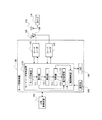
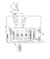
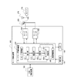
図1に示すように、カード読取装置100は、カードリーダ制御装置110と、アンテナコイル(以下、アンテナという。)126、136を備えたICカードリーダ(以下、カードリーダという。)120、130と、操作部140と、LED(Light Emitting Diode)150とを備えている。
カードリーダ制御装置110は、カードリーダ120、130の送信電力の調整を行い、カード読取装置100の運用時のカードリーダ120、130の送信電力を設定するものである。
As shown in FIG. 1, the
The card
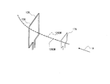
カードリーダ120、130は、常時電波を出力して自機のカード読み取り範囲に存在するICカード(以下、カードと略す。)と電波を用いて非接触により通信を行うものであり、変調方式や符号化の種類など通信条件が互いに異なっている。アンテナ126、136は、図2に示すように、図中の矢印A方向に見て互いに平面的に重なるように近接して配置されている。このため、アンテナ136はアンテナ126から放射される電磁波126EMにより干渉を受け、アンテナ126はアンテナ136から放射される電磁波136EMにより干渉を受ける。ただし、カードリーダ120、130はアンテナ126、136と矢印A方向に見て平面的に重なる近接した位置にアンテナ176が存在するカードと通信を行う。なお、後述する第2から第5の実施の形態におけるカード読取装置内のカードリーダが備えるアンテナ間の位置関係は図2に示すアンテナ間の位置関係と同様である。
The
操作部140は、カード読取装置100の入力装置であって、テンキー、確定キー、モード切替キーなどがある。モード切替キーは、カード読取装置100の動作をカードリーダ120、130の調整を行う調整モードに設定する場合に、また、調整モードを解除する場合に押下されるキーである。
LED150は、複数のLEDからなる。調整モード時に、カードリーダとカードとの間の通信の通信品質が予め定められた通信品質を超えていれば点灯するLED(以下、調整報済み知用のLEDという。)、予め定められた通信品質以下であれば点灯するLED(以下、未調整報知用のLEDという。)が割り当てられている。
The
The
カード読取装置100には上位制御装置160が接続されている。例えば、上位制御装置160はカードリーダ120、130からカードリーダ120、130がカードから読み取った識別番号が入力される。上位制御装置160は入力された識別番号が不図示の記憶装置内のデータベースに予め格納されている登録番号の何れかに一致すれば電気制御可能な入退室ドアの鍵の開錠を一定期間行う。
<カードリーダ制御装置構成>
図1に示すように、カードリーダ制御装置110は、モード切替部111と受付部112と検出部113と判断部114と電力設定部115と報知制御部116とを備える。
A
<Card reader controller configuration>
As shown in FIG. 1, the card
モード切替部111は、操作部140から入力されるモード切替キーの押下信号に基づき、カード読取装置100が調整モード以外のモードで動作しているときにはカード読取装置100の動作を調整モードに設定し、調整モードで動作しているときには調整モードを解除する。
受付部112は、調整モード時に操作部140から入力されるテンキーの押下信号に基づき、カードリーダ120、130のうちカードを読み取るカードリーダの指定を受け付ける。例えば、不図示のメモリにカードリーダ毎にカードリーダを識別するための識別番号を記憶しておき、作業者は操作部140のテンキーを利用して識別番号を入力することによってカードリーダの指定を行うことにより実現できる。
The mode switching unit 111 sets the operation of the
The accepting
検出部113は、受付部112によって指定を受け付けたカードリーダとカードとの間において行われる通信の誤り率を算出して、両者間において行われる通信の通信品質を検出する。誤り率の算出は、指定を受け付けたカードリーダから入力される当該カードリーダがカードに送信した送信データに対するカードの返信データの正誤に基づき、送信した送信データの回数に対する誤った返信データの回数の割合を算出することにより行う。なお、誤った返信データには返信データがなかった場合も含む。
The
判断部114は、検出部113により算出された誤り率が不図示のメモリに記憶されている予め定められた閾値以下であるか否かを判断し、誤り率が閾値を超えている場合に通信品質が予め定められた通信品質以下であると判断する。
電力設定部115は、判断部114により誤り率が閾値を越えていると判断された場合に、受付部112により指定を受け付けたカードリーダ以外のカードリーダに対して送信電力のレベルを1(dB)下げさせる制御信号を出力する。電力設定部115は、指定を受け付けたカードリーダ以外のカードリーダに対して制御信号を出力することによって、指定を受け付けたカードリーダ以外のカードリーダの送信電力のレベルを検出時の送信電力より1(dB)低い送信電力のレベルに設定する。
The
When the
報知制御部116は、判断部114により誤り率が閾値を越えていると判断された場合にLED150の未調整報知用のLEDを点灯させ、判断部114により誤り率が閾値以下であると判断された場合にLED150の調整済み報知用のLEDを点灯させる。
<カードリーダ構成>
以下、図1のカードリーダ120の構成について図3を参照しつつ説明する。図3は図1のカードリーダ120の装置構成を示す構成図である。
When the
<Card reader configuration>
Hereinafter, the configuration of the
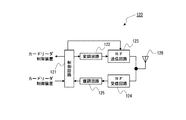
図3に示すように、カードリーダ120は、制御回路121と変調回路122とRF(Radio Frequency)送信回路123とRF受信回路124と復調回路125とアンテナ126とを備える。
制御回路121はカードリーダ120の各種制御を行うものである。制御回路121は、送信電力のレベルと変調速度との初期値を内部に保持しており、カードリーダ制御装置110の電力設定部115から入力される制御信号に基づき、内部に保持している送信電力のレベルを1(dB)下げた送信電力のレベルに変更して保持する。制御回路121は送信するデータを生成するとともに符号化して送信データを作成し、内部に保持している変調速度で送信データのデータを切り替えて変調回路122に供給する。また、制御回路121は保持している送信電力のレベルをRF送信回路123へ出力する。さらに、制御回路121は復調回路125から入力される返信データを解読する。
As shown in FIG. 3, the
The
変調回路122は制御回路121から供給される送信データで搬送波(例えば、周波数13.56(MHz)の搬送波)を所定の変調方式(例えば、変調率が100(%)のASK(Amplitude Shift Keying)方式)で変調する。RF送信回路123は制御回路121から入力される送信電力のレベルに搬送波の電力レベルがなるようにアンテナ126に流す電流の大きさを調整して送信データをアンテナ126から放射する。
The
RF受信回路124はカードからアンテナ126を介して入力される返信データを増幅し、変調速度に応じた帯域幅のフィルタでフィルタリングして帯域制限を行い、復調回路125はRF受信回路124による処理後の返信データを復調し、復調後の返信データを制御回路121へ出力する。
なお、カードリーダ130はカードリーダ120と変調方式や符号化の種類など通信条件が異なるものであるが、本発明に関連する部分はカードリーダ120と実質的に同様であるためその説明を省略する。例えば、カードリーダ130の変調方式は変調率が10(%)のASK方式である。
<カード構成>
以下、図1のカード170の構成について図4を参照しつつ説明する。図4は図1のカード170の装置構成を示す構成図である。
The
The
<Card configuration>
The configuration of the
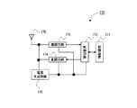
図4に示すように、カード170は、負荷変調を行うものであり、記憶装置171と復調回路172と制御回路173と変調回路174と電源生成回路175とアンテナ176とを備える。
記憶装置171はカード170に一意に割り振られた識別番号や自身の公開鍵と秘密鍵とのペアや変調速度などを記憶する。
As shown in FIG. 4, the
The
復調回路172はアンテナ176によって受信されるカードリーダからの送信データを復調して制御回路173へ出力する。制御回路173は、復調回路172から入力される復調後の送信データを復号して解読し、解読した送信データに基づき、記憶装置171から識別番号を取り出して符号化するなどして、返信データを生成する。そして、制御回路173は、記憶装置171に記憶されている変調速度で返信データのデータを切り替えて変調回路174に供給する。変調回路174は、制御回路173から入力される返信データで副搬送波(例えば、周波数が847.5(kHz)の副搬送波)を変調し、アンテナ176により受信された無変調区間の搬送波により変調後の返信データをアンテナ176から送信する。
The
電源生成回路175はアンテナ176により受信された電磁波よりカード170内で使用する電力を生成して各部へ供給する。
<カードリーダとカード間の通信>
以下、カードリーダ120とカード170との間で行われる通信の概略について記載する。
The
<Communication between card reader and card>
Hereinafter, an outline of communication performed between the
カードリーダ120の制御回路121は送信するデータを生成するとともに符号化して送信データを作成し、変調速度で送信データのデータを切り替えて変調回路122に供給する。変調回路122は制御回路121から供給される送信データで搬送波を変調し、RF送信回路123は制御回路121から入力される送信電力のレベルに応じてアンテナ126に流す電流の大きさを調整して送信データを送信する。
The
カード170はアンテナ176により受信される電磁波から電源生成回路175により電力を生成し、電源生成回路175から各部に電力を供給する。これにより、各部が起動する。復調回路172はカードリーダからの送信データを復調し、制御回路173は復調後の送信データを復号して解読する。そして、制御回路173は解読した送信データに基づいて返信データを生成し、変調速度で返信データのデータを切り替えて変調回路174に供給する。変調回路174は返信データで副搬送波を変調し、無変調区間の搬送波により変調後の返信データをアンテナ176から送信する。
The
カードリーダ120はアンテナ126によってカード170から返信データを受信すると、RF受信回路124は受信した返信データを増幅などし、復調回路125は処理後の返信データを復調する。そして、制御回路121は復調後の返信データを解読する。制御回路121は、カード読取装置100が調整モードで動作している場合、解読した返信データに基づき送信データに対する返信データの正誤を判断し、判断結果をカードリーダ制御装置110へ出力する。
<カードリーダ制御装置の動作>
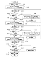
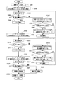
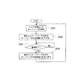
以下、カードリーダ制御装置110によって行われるカードリーダの送信電力を調整する調整動作について図5を参照しつつ説明する。図5は本実施の形態のカードリーダ制御装置が行うカードリーダの調整動作の流れを示すフローチャートである。
When the
<Operation of Card Reader Control Device>
Hereinafter, an adjustment operation for adjusting the transmission power of the card reader performed by the
カード読取装置110のカードリーダ120、130の運用時の送信電力の設定を行うために、作業者は操作部140のモード切替キーを押下する。モード切替部111は操作部140から入力されるモード切替キーの押下信号に基づきカード読取装置100の動作をカードリーダ120、130の送信電力の調整を行う調整モードに設定する(ステップS101)。
In order to set the transmission power when the
モード切替キーの押下後、作業者は操作部140のテンキーを利用してカードリーダ120の識別番号を入力してカードリーダ120の指定を行う。受付部112は操作部140から入力される押下信号に基づきカードリーダ120の指定を受け付ける(ステップS102)。
作業者は指定を行ったカードリーダ120に対応したカードをカードリーダ120のカード読み取り範囲にかざす。カードリーダの指定を受け付けてから或いはLED150の未調整報知用のLEDを点灯させてから所定時間(例えば、3秒)経過後に、カードリーダ120は、複数回、カード読み取り範囲に存在するカードに対して送信データを送信してこれに対する返信データを受信する。そして、カードリーダ120は返信データの正誤を判断し、判断結果をカードリーダ制御装置110へ出力する。検出部113は、カードリーダ120から入力される判断結果に基づき、カードリーダ120とカードとの間で行われる通信の誤り率を算出する(ステップS103)。判断部114はステップS103において算出された誤り率が予め定められた閾値以下であるか否かを判断する(ステップS104)。
After pressing the mode switching key, the operator inputs the identification number of the
The operator holds the card corresponding to the designated
ステップS104において算出された誤り率が閾値を越えていると判断された場合(S104:NO)、電力設定部115はステップS102において受け付けたカードリーダ120以外のカードリーダ130に対して送信電力のレベルを1(dB)下げさせる制御信号を出力する(ステップS105)。この制御信号により、カードリーダ130の制御回路は内部に保持している送信電力のレベルを1(dB)下げた値に変更して保持することになる。報知制御部116は、作業者に調整ができていないことを知らしめるために、LED150の未調整報知用のLEDを点灯させ(ステップS106)、ステップS103に戻る。
When it is determined that the error rate calculated in step S104 exceeds the threshold (S104: NO), the
ステップS104において誤り率が閾値以下であると判断された場合(S104:YES)、報知制御部116は、作業者に調整ができたことを知らしめるために、LED150の調整済み報知用のLEDを点灯させ(ステップS107)、ステップS108の処理へ進む。
作業者は調整済み報知用のLEDの点灯後、操作部140のテンキーを利用してカードリーダ130の識別番号を入力してカードリーダ130の指定を行う。受付部112は操作部140から入力される押下信号に基づきカードリーダ130の指定を受け付ける(ステップS108)。
When it is determined in step S104 that the error rate is equal to or lower than the threshold (S104: YES), the
After the adjusted notification LED is turned on, the operator inputs the identification number of the
作業者は指定を行ったカードリーダ130に対応したカードをカードリーダ130のカード読み取り範囲にかざす。カードリーダの指定を受け付けてから或いはLED150の未調整報知用のLEDを点灯させてから所定時間後に、カードリーダ130は、複数回、カード読み取り範囲に存在するカードに対して送信データを送信してこれに対する返信データを受信する。そして、カードリーダ130は返信データの正誤を判断し、判断結果をカードリーダ制御装置110へ出力する。検出部113は、カードリーダ130から入力される判断結果に基づき、カードリーダ130とカードとの間で行われる通信の誤り率を算出する(ステップS109)。判断部114はステップS109において算出された誤り率が予め定められた閾値以下であるか否かを判断する(ステップS110)。
The operator holds the card corresponding to the designated
ステップS110において、算出された誤り率が閾値を越えていると判断された場合(S110:NO)、電力設定部115はステップS108において受け付けたカードリーダ130以外のカードリーダ120に対して送信電力のレベルを1(dB)下げさせる制御信号を出力する(ステップS111)。この制御信号により、カードリーダ120の制御回路121は内部に保持している送信電力のレベルを1(dB)下げた値に変更して保持することになる。報知制御部116は、LED150の未調整報知用のLEDを点灯させ(ステップS112)、ステップS109に戻る。
In step S110, when it is determined that the calculated error rate exceeds the threshold (S110: NO), the
ステップS110において誤り率が閾値以下であると判断された場合(S110:YES)、報知制御部116は、LED150の調整済み報知用のLEDを点灯させ(ステップS113)、ステップS114の処理へ進む。
作業者は調整済み報知用のLEDの点灯後、ステップS108からステップS113の処理により最初に指定したカードリーダ120がカードと行う通信の通信品質が予め定められた通信品質以下になっていないかを確認するために、操作部140のテンキーを利用してカードリーダ120の識別番号を入力してカードリーダ120の指定を行う。受付部112は操作部140から入力される押下信号に基づきカードリーダ120の指定を受け付ける(ステップS114)。
When it is determined in step S110 that the error rate is equal to or less than the threshold (S110: YES), the
After the adjusted notification LED is turned on, the operator checks whether the communication quality of communication performed by the
作業者は指定を行ったカードリーダ120に対応したカードをカードリーダ120のカード読み取り範囲にかざし、カード読取装置100においてステップS103の場合と実質的に同様の処理が行われて、検出部113はカードリーダ120とカードとの間で行われる通信の誤り率を算出する(ステップS115)。判断部114はステップS115において算出された誤り率が予め定められた閾値以下であるか否かを判断する(ステップS116)。
The operator holds the card corresponding to the designated
ステップS116において誤り率が閾値以下であると判断された場合(S116:YES)、報知制御部116は、作業者に調整ができたことを知らしめるために、LED150の調整済み報知用のLEDを点灯させる(ステップS117)。そして、作業者は操作部140のモード切替キーを押下し、モード切替部111は操作部140から入力されるモード切替キーの押下信号に基づきカード読取装置100の調整モードを解除し(ステップS119)、処理を終了する。なお、カードリーダ120、130は、カード読取装置100の運用時には上記の処理により設定された送信電力のレベルで電波を出力することになる。
When it is determined in step S116 that the error rate is equal to or less than the threshold (S116: YES), the
ステップS116において誤り率が閾値を越えていると判断された場合(S116:NO)、報知制御部116は、作業者に調整ができたことを知らしめるために、LED150の未調整報知用のLEDを点灯させる(ステップS118)。そして、作業者は操作部140のモード切替キーを押下し、モード切替部111は操作部140から入力されるモード切替キーの押下信号に基づきカード読取装置100の調整モードを解除し(ステップS119)、処理を終了する。
When it is determined in step S116 that the error rate exceeds the threshold (S116: NO), the
以上説明したように、第1の実施の形態によれば、指定されたカードリーダとカードとの間で行われる通信の通信品質が予め定められた通信品質以下であれば、指定されたカードリーダからみてノイズ源となるカードリーダの送信電力を低下させ、指定されたカードリーダが受信するノイズの電力レベルを下げている。このため、搬送波の周波数を変更することなく、カードリーダが他のカードリーダから干渉を受けてカードと通信ができなくなるような状況を回避できるようになる。
《第2の実施の形態》
以下、本発明の第2の実施の形態におけるカードリーダ制御装置について図面を参照しつつ説明する。なお、複数のカードリーダの導入時やメンテナンス時などに、カードリーダが他のカードリーダから干渉を受けてカードと行う通信の通信品質が予め定められた通信品質以下にならないように、第1の実施の形態におけるカードリーダ制御装置はカードリーダの送信電力を調整するものであるのに対して、第2の実施の形態におけるカードリーダ制御装置はカードリーダの変調速度を調整するものである。
<全体構成>
本発明の第2の実施の形態におけるカードリーダ制御装置を含むシステム全体の構成について図6を参照しつつ説明する。図6は本実施の形態におけるカードリーダ制御装置を含むシステム全体の構成を示すシステム構成図である。なお、第1の実施の形態と同様の構成要素には同じ符号を付し、その説明を省略する。
As described above, according to the first embodiment, if the communication quality of communication performed between the specified card reader and the card is equal to or lower than the predetermined communication quality, the specified card reader is used. Accordingly, the transmission power of the card reader, which is a noise source, is reduced, and the power level of noise received by the designated card reader is reduced. For this reason, it becomes possible to avoid a situation in which the card reader is unable to communicate with the card due to interference from other card readers without changing the frequency of the carrier wave.
<< Second Embodiment >>
Hereinafter, a card reader control device according to a second embodiment of the present invention will be described with reference to the drawings. Note that the communication quality of communication performed by the card reader with the card due to interference from other card readers at the time of introduction or maintenance of a plurality of card readers does not fall below a predetermined communication quality. The card reader control device in the embodiment adjusts the transmission power of the card reader, whereas the card reader control device in the second embodiment adjusts the modulation speed of the card reader.
<Overall configuration>
The configuration of the entire system including the card reader control device according to the second embodiment of the present invention will be described with reference to FIG. FIG. 6 is a system configuration diagram showing the configuration of the entire system including the card reader control device in the present embodiment. In addition, the same code | symbol is attached | subjected to the component similar to 1st Embodiment, and the description is abbreviate | omitted.
カード読取装置200は、カードリーダ制御装置210と、アンテナ226、236を備えたカードリーダ220、230と、操作部140と、LED150とを備えており、カード読取装置200は上位制御装置160に接続されている。
第1の実施の形態のカードリーダ120、130がカードリーダ110からの制御信号に基づき制御回路内に保持している送信電力のレベルを変更する。これに対して、カードリーダ220、230は、カードリーダ制御装置210の後述する変調速度設定部215からの制御信号に基づき、制御回路内に保持している変調速度を制御信号に含まれる変調速度に変更する。カードリーダ220、230は、変調速度に変更があった場合には変更後の変調速度で送信データのデータを切り替える。なお、それ以外の機能については第1の実施の形態のカードリーダ120、130と同様である。
<カードリーダ制御装置構成>
図6に示すように、カードリーダ制御装置210は、モード切替部211と受付部212と検出部213と判断部214と変調速度設定部215と報知制御部216とを備える。モード切替部211、受付部212、検出部213、判断部214、および報知制御部216は、夫々、第1の実施の形態のモード切替部111、受付部112、検出部113、判断部114、および報知制御部116と同様であり、第1の実施の形態の説明が適用できるため説明を省略する。
The
The
<Card reader controller configuration>
As illustrated in FIG. 6, the card
変調速度設定部215は、内部に複数の変調速度を示す数値データ(106ksps、212ksps、424ksps、848ksps)を保持している。変調速度設定部215は、判断部214により誤り率が閾値を越えていると判断された場合に、受付部212により指定を受け付けたカードリーダに対して検出時の変調速度より1段階遅い変調速度(内部に保持している変調速度を示す数値データのうち、検出時の変調速度を示す数値データより小さいものであって、かつ、最大の変調速度を示す数値データ)を含む制御信号を出力する。変調速度設定部215は、指定を受け付けたカードリーダに対して制御信号を出力することによって、指定を受け付けたカードリーダの変調速度を検出時の変調速度より1段階遅い変調速度に設定する。なお、変調速度を大きい順番に使用することにより、カード読取装置200の調整を行う作業者は、調整作業時にカードリーダ220、230が使用する変調速度を知ることができる。
<カードリーダ制御装置の動作>
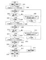
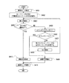
以下、カードリーダ制御装置210によって行われるカードリーダの変調速度を調整する調整動作について図7を参照しつつ説明する。図7は本実施の形態のカードリーダ制御装置が行うカードリーダの調整動作の流れを示すフローチャートである。
The modulation
<Operation of Card Reader Control Device>
Hereinafter, the adjustment operation for adjusting the modulation speed of the card reader performed by the
モード切替部211は操作部140から入力されるモード切替キーの押下信号に基づきカード読取装置200の動作をカードリーダ220、230の変調速度の調整を行う調整モードに設定する(ステップS201)。
受付部212は操作部140から入力されるテンキーの押下信号に基づき作業者が識別番号を入力することによって指定したカードリーダ220の指定を受け付ける(ステップS202)。
The
The accepting
作業者は指定を行ったカードリーダ220に対応した現時点でのカードリーダ220の変調速度と同じ変調速度のカードをカードリーダ220のカード読み取り範囲にかざす。第1の実施の形態において説明したステップS103と実質的に同様の処理がカード読取装置200において行われて、検出部213はカードリーダ220とカードとの間で行われる通信の誤り率を算出する(ステップS203)。判断部214はステップS203において算出された誤り率が予め定められた閾値以下であるか否かを判断する(ステップS204)。
The operator holds the card having the same modulation speed as the
ステップS204において算出された誤り率が閾値を越えていると判断された場合(S204:NO)、変調速度設定部215はステップS202において受け付けたカードリーダ220に対して検出時の変調速度より1段階遅い変調速度を含む制御信号を出力する(ステップS205)。この制御信号により、カードリーダ220の制御回路は内部に保持している変調速度を制御信号に含まれる検出時の変調速度より1段階遅い変調速度に変更することになる。報知制御部216は、LED150の未調整報知用のLEDを点灯させ(ステップS206)、ステップS203に戻る。
When it is determined that the error rate calculated in step S204 exceeds the threshold (S204: NO), the modulation
ステップS204において誤り率が閾値以下であると判断された場合には(S204:YES)、報知制御部216は、LED150の調整済み報知用のLEDを点灯させ(ステップS207)、ステップS208の処理へ進む。
調整済み報知用のLEDの点灯後、受付部212は操作部140から入力されるテンキーの押下信号に基づき作業者が識別番号を入力することによって指定したカードリーダ230の指定を受け付ける(ステップS208)。
When it is determined in step S204 that the error rate is equal to or lower than the threshold (S204: YES), the
After the adjusted notification LED is turned on, the accepting
作業者は指定を行ったカードリーダ230に対応した現時点でのカードリーダ230の変調速度と同じ変調速度のカードをカードリーダ230のカード読み取り範囲にかざす。第1の実施の形態において説明したステップS109と実質的に同様の処理がカード読取装置200において行われて、検出部213はカードリーダ230とカードとの間で行われる通信の誤り率を算出する(ステップS209)。判断部214はステップS209において算出された誤り率が予め定められた閾値以下であるか否かを判断する(ステップS210)。
The operator holds a card having the same modulation speed as the
ステップS210において算出された誤り率が閾値を越えていると判断された場合(S210:NO)、変調速度設定部215はステップS208において受け付けたカードリーダ230に対して検出時の変調速度より1段階遅い変調速度を含む制御信号を出力する(ステップS211)。この制御信号により、カードリーダ230の制御回路は内部に保持している変調速度を制御信号に含まれる検出時の変調速度より1段階遅い変調速度に変更することになる。報知制御部216は、LED150の未調整報知用のLEDを点灯させ(ステップS212)、ステップS209に戻る。
When it is determined that the error rate calculated in step S210 exceeds the threshold (S210: NO), the modulation
ステップS210において誤り率が閾値以下であると判断された場合には(S210:YES)、報知制御部216は、LED150の調整済み報知用のLEDを点灯させ(ステップS213)、ステップS214の処理へ進む。
作業者は調整済み報知用のLEDの点灯後、最初に指定したカードリーダ120がステップS208からステップS213の処理によりカードとの間の通信品質が予め定められた通信品質以下になっていないかを確認する。受付部212は操作部140から入力されるテンキーの押下信号に基づき作業者が識別番号を入力することによって指定したカードリーダ220の指定を受け付ける(ステップS214)。
If it is determined in step S210 that the error rate is equal to or less than the threshold (S210: YES), the
After the adjusted notification LED is turned on, the operator determines whether the first designated
作業者は指定を行ったカードリーダ220に対応した現時点でのカードリーダ220の変調速度と同じ変調速度のカードをカードリーダ220のカード読み取り範囲にかざす。第1の実施の形態において説明したステップS103と実質的に同様の処理がカード読取装置200において行われて、検出部213はカードリーダ220とカードとの間で行われる通信の誤り率を算出する(ステップS215)。判断部214はステップS215において算出された誤り率が予め定められた閾値以下であるか否かを判断する(ステップS216)。
The operator holds the card having the same modulation speed as the
ステップS216において誤り率が閾値以下であると判断された場合(S216:YES)、報知制御部216は、LED150の調整済み報知用のLEDを点灯させる(ステップS217)。そして、作業者は操作部140のモード切替キーを押下し、モード切替部211は操作部140から入力されるモード切替キーの押下信号に基づきカード読取装置200の調整モードを解除し(ステップS219)、処理を終了する。なお、カードリーダ220、230は、カード読取装置200の運用時には上記の処理により設定された変調速度により送信データの切り替えを行うことになる。
When it is determined in step S216 that the error rate is equal to or lower than the threshold (S216: YES), the
ステップS216において誤り率が閾値を越えていると判断された場合(S216:NO)、報知制御部216は、LED150の未調整報知用のLEDを点灯させる(ステップS218)。そして、作業者は操作部140のモード切替キーを押下し、モード切替部211は操作部140から入力されるモード切替キーの押下信号に基づきカード読取装置200の調整モードを解除し(ステップS219)、処理を終了する。
When it is determined in step S216 that the error rate exceeds the threshold (S216: NO), the
以上説明したように、第2の実施の形態によれば、指定されたカードリーダとカードとの間で行われる通信の通信品質が予め定められた通信品質以下であれば、指定されたカードリーダの変調速度を変更する。これによって、例えば、側波帯の周波数領域がノイズ源となるカードリーダが出力する電波の電力レベルが低い周波数領域に移動すれば、指定されたカードリーダにおいて信号成分を含む側波帯の周波数領域でのノイズの電力レベルが低下する。このため、搬送波の周波数を変更することなく、カードリーダが他のカードリーダから干渉を受けてカードと通信ができなくなるような状況を回避できる。
《第3の実施の形態》
以下、本発明の第3の実施の形態におけるカードリーダ制御装置について図面を参照しつつ説明する。なお、複数のカードリーダの導入時やメンテナンス時などに、カードリーダが他のカードリーダから干渉を受けてカードと行う通信の通信品質が予め定められた通信品質以下にならないように、第1の実施の形態におけるカードリーダ制御装置はカードリーダの送信電力を調整するものであるのに対して、第3の実施の形態におけるカードリーダ制御装置はカードリーダの変調速度と送信電力とを調整するものである。
<全体構成>
本発明の第3の実施の形態におけるカードリーダ制御装置を含むシステム全体の構成について図8を参照しつつ説明する。図8は本実施の形態におけるカードリーダ制御装置を含むシステム全体の構成を示すシステム構成図である。なお、第1の実施の形態と同様の構成要素には同じ符号を付し、その説明を省略する。
As described above, according to the second embodiment, if the communication quality of communication performed between the specified card reader and the card is equal to or lower than the predetermined communication quality, the specified card reader is used. Change the modulation speed. Thus, for example, if the frequency region of the sideband moves to a frequency region where the power level of the radio wave output from the card reader that is a noise source is low, the frequency region of the sideband that includes the signal component in the designated card reader The power level of noise at For this reason, it is possible to avoid a situation in which the card reader is unable to communicate with the card due to interference from another card reader without changing the frequency of the carrier wave.
<< Third Embodiment >>
Hereinafter, a card reader control device according to a third embodiment of the present invention will be described with reference to the drawings. Note that the communication quality of communication performed by the card reader with the card due to interference from other card readers at the time of introduction or maintenance of a plurality of card readers does not fall below a predetermined communication quality. The card reader control device in the embodiment adjusts the transmission power of the card reader, whereas the card reader control device in the third embodiment adjusts the modulation speed and transmission power of the card reader. It is.
<Overall configuration>
The configuration of the entire system including the card reader control device according to the third embodiment of the present invention will be described with reference to FIG. FIG. 8 is a system configuration diagram showing the configuration of the entire system including the card reader control device in the present embodiment. In addition, the same code | symbol is attached | subjected to the component similar to 1st Embodiment, and the description is abbreviate | omitted.
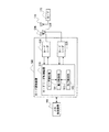
カード読取装置300は、カードリーダ制御装置310と、アンテナ326、336を備えたカードリーダ320、330と、操作部140と、LED150とを備えており、カード読取装置300は上位制御装置160に接続されている。
第1の実施の形態のカードリーダ120、130はカードリーダ110からの制御信号に基づき制御回路内に保持している送信電力のレベルを変更する。これに対して、カードリーダ320、330は、カードリーダ制御装置310の後述する変調速度設定部315からの制御信号に基づき制御回路内に保持している変調速度を制御信号に含まれる変調速度に変更する。また、カードリーダ320、330は、カードリーダ制御装置310後述する電力設定部317からの制御信号に基づき制御回路内に保持している送信電力のレベルを制御信号に含まれる送信電力のレベルに変更する。カードリーダ320、330は、変調速度に変更があった場合には変更後の変調速度で送信データのデータを切り替え、送信電力のレベルに変更があった場合には変更後の送信電力のレベルで電波を出力する。なお、それ以外の機能については第1の実施の形態のカードリーダ120、130と同様である。
<カードリーダ制御装置構成>
図8に示すように、カードリーダ制御装置310は、モード切替部311と受付部312と検出部313と判断部314と変調速度設定部315と記憶部316と電力設定部317と報知制御部318とを備える。モード切替部311、受付部312、検出部313、判断部314、および報知制御部318は、夫々、第1の実施の形態のモード切替部111、受付部112、検出部113、判断部114、および報知制御部116と同様であり、第1の実施の形態の説明が適用できるため説明を省略する。また、変調速度設定部315は、第2の実施の形態の変調速度設定部215と同様であり、第2の実施の形態の説明が適用できるため説明を省略する。
The
The
<Card reader controller configuration>
As illustrated in FIG. 8, the card
記憶部316は、変調速度毎に送信電力のレベルを記憶しており、記憶されている送信電力のレベルは変調速度が遅い方が大きいレベルになっている。ただし、誘導式読み書き通信設備に関して、電波法により変調速度における側波帯の電力レベルの上限が定められており、側波帯の電力レベルの上限は変調速度が遅くなるにつれて大きくなるようになっている。記憶部316に記憶される変調速度毎の送信電力のレベルは電波法の誘電式読み書き通信設備に関する規制を満たすようにしている。なお、変調方式がASK方式の場合、搬送波の振幅レベルをA1、変調度をmとすれば、側波帯の振幅レベルはm×A1/2である。
The
電力設定部317は、受付部312が指定を受け付けたカードリーダに対して、記憶部316に記憶されている変調速度設定部315による変更後の変調速度に対応した、検出時の送信電力のレベルより大きい、送信電力のレベルを含む制御信号を出力する。電力設定部317は、指定を受け付けたカードリーダに対して制御信号を出力することによって、指定を受け付けたカードリーダの送信電力のレベルを検出時の送信電力のレベルより大きい変更後の変調速度に対応した送信電力のレベルに設定する。
<カードリーダ制御装置調整概要>
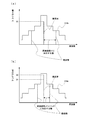
以下、本実施の形態におけるカードリーダ制御装置によるカードリーダの調整の概要について図9を参照しつつ説明する。図9は本実施の形態のカードリーダ制御装置によるカードリーダの調整を説明するための図である。図9におけるレベル316aは電波法の誘導式読み書き通信設備に関して規制された変調速度に対する側波帯の電力レベルの上限を示している。記憶部316に記憶される変調速度毎の送信電力のレベルは、電波法の誘電式読み書き通信設備に関する変調速度に対する側波帯の電力レベルの上限を超えないように(ここでは、上限となるように)、側波帯の電力レベルと変調度とを考慮して設定される。
The
<Outline of card reader control device adjustment>
Hereinafter, an outline of adjustment of the card reader by the card reader control device according to the present embodiment will be described with reference to FIG. FIG. 9 is a diagram for explaining adjustment of the card reader by the card reader control device of the present embodiment.
カードリーダ320の変調速度がv1、搬送波の電力レベルがV1であった場合(図9(a))に、カードリーダ320がカードと行う通信の通信品質が予め定められた通信品質以下であったとする。このとき、変調速度設定部315はカードリーダ320の変調速度を一段階変調速度を遅らせて変調速度v2に設定する。電力設定部317は、変調速度v2では変調速度v1に比べて搬送波の送信電力のレベルを大きくすることができるので、搬送波の電力レベルがV2になるようにカードリーダ320の送信電力のレベルを設定する。搬送波の電力レベルが大きくなることによって、側波帯の電力レベルも大きくなる。
<カードリーダ制御装置の動作>
以下、カードリーダ制御装置310によって行われるカードリーダの変調速度および送信電力を調整する調整動作について図10を参照しつつ説明する。図10は本実施の形態のカードリーダ制御装置が行うカードリーダの調整動作の流れを示すフローチャートである。
When the modulation speed of the
<Operation of Card Reader Control Device>
Hereinafter, an adjustment operation for adjusting the modulation speed and transmission power of the card reader performed by the
モード切替部311は操作部140から入力されるモード切替キーの押下信号に基づきカード読取装置300の動作をカードリーダ320、330の変調速度および送信電力のレベルの調整を行う調整モードに設定する(ステップS301)。
受付部312は操作部140から入力されるテンキーの押下信号に基づき作業者が識別番号を入力することによって指定したカードリーダ320の指定を受け付ける(ステップS302)。
The
The accepting
作業者は指定を行ったカードリーダ320に対応した現時点でのカードリーダ320の変調速度と同じ変調速度のカードをカードリーダ320のカード読み取り範囲にかざす。第1の実施の形態において説明したステップS103と実質的に同様の処理がカード読取装置300において行われて、検出部313はカードリーダ320とカードとの間で行われる通信の誤り率を算出する(ステップS303)。判断部314はステップS303において算出された誤り率が予め定められた閾値以下であるか否かを判断する(ステップS304)。
The operator holds a card having the same modulation speed as the
ステップS304において算出された誤り率が閾値を越えていると判断された場合(S304:NO)、変調速度設定部315はステップS302において受け付けたカードリーダ320に対して検出時の変調速度より1段階遅い変調速度を含む制御信号を出力する(ステップS305)。この制御信号により、カードリーダ320の制御回路は内部に保持している変調速度を制御信号に含まれる検出時の変調速度より1段階遅い変調速度に変更する。電力設定部317は記憶部316から変更後の変調速度に対応した送信電力のレベルを取り出し、取り出した送信電力のレベルが指定を受け付けたカードリーダ320の現在の送信電力のレベルより大きいか否か、つまり、送信電力を大きくできるか否かを判断する(ステップS306)。
When it is determined that the error rate calculated in step S304 exceeds the threshold (S304: NO), the modulation
ステップS306において送信電力のレベルを大きくできないと判断された場合(S306:NO)、報知制御部318はLED150の未調整報知用のLEDを点灯させ(ステップS308)、ステップS303に戻る。
ステップS306において送信電力のレベルを大きくできると判断された場合(S306:YES)、電力設定部317はステップS302において受け付けたカードリーダ320に対して記憶部316から取り出した送信電力のレベルを含む制御信号を出力する(ステップS307)。この制御信号により、カードリーダ320の制御回路は内部に保持している送信電力のレベルを制御信号に含まれる検出時の送信電力のレベルより大きい変更後の変調速度に対応した送信電力のレベルに変更することになる。そして、報知制御部318はLED150の未調整報知用のLEDを点灯させ(ステップS308)、ステップS303に戻る。
If it is determined in step S306 that the transmission power level cannot be increased (S306: NO), the
When it is determined in step S306 that the transmission power level can be increased (S306: YES), the
ステップS304において誤り率が閾値以下であると判断された場合(S304:YES)、報知制御部318はLED150の調整済み報知用のLEDを点灯させ(ステップS309)、ステップS310の処理へ進む。
調整済み報知用のLEDの点灯後、受付部312は操作部140から入力されるテンキーの押下信号に基づき作業者が識別番号を入力することによって指定したカードリーダ330の指定を受け付ける(ステップS310)。
If it is determined in step S304 that the error rate is equal to or less than the threshold (S304: YES), the
After the adjusted notification LED is turned on, the accepting
作業者は指定を行ったカードリーダ330に対応した現時点でのカードリーダ330の変調速度と同じ変調速度のカードをカードリーダ330のカード読み取り範囲にかざす。第1の実施の形態において説明したステップS109と実質的に同様の処理がカード読取装置300において行われて、検出部313はカードリーダ330とカードとの間で行われる通信の誤り率を算出する(ステップS311)。判断部314はステップS311において算出された誤り率が予め定められた閾値以下であるか否かを判断する(ステップS312)。
The operator holds a card having the same modulation speed as the
ステップS312において算出された誤り率が閾値を越えていると判断された場合(S312:NO)、変調速度設定部315はステップS310において受け付けたカードリーダ330に対して検出時の変調速度より1段階遅い変調速度を含む制御信号を出力する(ステップS313)。この制御信号により、カードリーダ330の制御回路は内部に保持している変調速度を制御信号に含まれる検出時の変調速度より1段階遅い変調速度に変更する。電力設定部317は記憶部316から変更後の変調速度に対応した送信電力のレベルを取り出し、取り出した送信電力のレベルが指定を受け付けたカードリーダ330の現在の送信電力のレベルより大きいか否か、つまり、送信電力を大きくできるか否かを判断する(ステップS314)。
When it is determined that the error rate calculated in step S312 exceeds the threshold (S312: NO), the modulation
ステップS314において送信電力のレベルを大きくできないと判断された場合(S314:NO)、報知制御部318はLED150の未調整報知用のLEDを点灯させ(ステップS316)、ステップS311に戻る。
ステップS314において送信電力のレベルを大きくできると判断された場合(S314:YES)、電力設定部317はステップS310において受け付けたカードリーダ330に対して記憶部316から取り出した送信電力のレベルを含む制御信号を出力する(ステップS315)。この制御信号により、カードリーダ330の制御回路は内部に保持している送信電力のレベルを制御信号に含まれる検出時の送信電力のレベルより大きい変更後の変調速度に対応した送信電力のレベルに変更することになる。そして、報知制御部318はLED150の未調整報知用のLEDを点灯させ(ステップS316)、ステップS311に戻る。
If it is determined in step S314 that the transmission power level cannot be increased (S314: NO), the
If it is determined in step S314 that the transmission power level can be increased (S314: YES), the
ステップS312において誤り率が閾値以下であると判断された場合(S312:YES)、報知制御部318はLED150の調整済み報知用のLEDを点灯させ(ステップS317)、ステップS318の処理へ進む。
作業者は調整済み報知用のLEDの点灯後、ステップS310からステップS317の処理により最初に指定したカードリーダ320がカードと行う通信の通信品質が予め定められた通信品質以下になっていないかを確認する。受付部312は操作部140から入力されるテンキーの押下信号に基づき作業者が識別番号を入力することによって指定したカードリーダ320の指定を受け付ける(ステップS318)。
When it is determined in step S312 that the error rate is equal to or less than the threshold (S312: YES), the
After the adjusted notification LED is turned on, the operator checks whether the communication quality of communication performed by the
作業者は指定を行ったカードリーダ320に対応した現時点でのカードリーダ320の変調速度と同じ変調速度のカードをカードリーダ320のカード読み取り範囲にかざす。第1の実施の形態において説明したステップS103と実質的に同様の処理がカード読取装置300において行われて、検出部313はカードリーダ320とカードとの間で行われる通信の誤り率を算出する(ステップS319)。判断部314はステップS319において算出された誤り率が予め定められた閾値以下であるか否かを判断する(ステップS320)。
The operator holds a card having the same modulation speed as the
ステップS320において誤り率が閾値以下であると判断された場合(S320:YES)、報知制御部318はLED150の調整済み報知用のLEDを点灯させる(ステップS321)。そして、作業者は操作部140のモード切替キーを押下し、モード切替部311は操作部140から入力されるモード切替キーの押下信号に基づきカード読取装置300の調整モードを解除し(ステップS323)、処理を終了する。なお、カードリーダ320、330は、カード読取装置300の運用時には上記の処理により設定された変調速度により送信データの切り替えを行い、設定された送信電力のレベルで電波を出力することになる。
When it is determined in step S320 that the error rate is equal to or less than the threshold value (S320: YES), the
ステップS320において誤り率が閾値を越えていると判断された場合(S320:NO)、報知制御部318はLED150の未調整報知用のLEDを点灯させる(ステップS322)。そして、作業者は操作部140のモード切替キーを押下し、モード切替部311は操作部140から入力されるモード切替キーの押下信号に基づきカード読取装置300の調整モードを解除し(ステップS323)、処理を終了する。
If it is determined in step S320 that the error rate exceeds the threshold (S320: NO), the
以上説明したように、第3の実施の形態によれば、指定されたカードリーダとカードとの間で行われる通信の通信品質が予め定められた通信品質以下であれば、指定されたカードリーダの変調速度を遅くする。これによって、例えば、側波帯の周波数領域がノイズ源となるカードリーダが出力する電波の電力レベルが低い周波数領域に移動すれば、指定されたカードリーダにおいて信号成分を含む側波帯の周波数領域でのノイズの電力レベルが低下する。また、指定されたカードリーダが変更後の変調速度において送信電力のレベルを大きくできる場合には送信電力のレベルを大きくして、指定されたカードリーダが受信する受信信号の電力レベルを大きくしている。これにより、搬送波の周波数を変更することなく、カードリーダが他のカードリーダから干渉を受けてカードと通信ができなくなるような状況を回避できる。
《第4の実施の形態》
以下、本発明の第4の実施の形態におけるカードリーダ制御装置について図面を参照しつつ説明する。なお、複数のカードリーダの導入時やメンテナンス時などに、カードリーダが他のカードリーダから干渉を受けてカードと行う通信の通信品質が予め定められた通信品質以下にならないように、第1の実施の形態におけるカードリーダ制御装置はカードリーダの送信電力を調整するものであるのに対して、第4の実施の形態におけるカードリーダ制御装置はカードリーダが電波を出力する出力タイミングを調整するものである。
<全体構成>
本発明の第4の実施の形態におけるカードリーダ制御装置を含むシステム全体の構成について図11を参照しつつ説明する。図11は本実施の形態におけるカードリーダ制御装置を含むシステム全体の構成を示すシステム構成図である。なお、第1の実施の形態と同様の構成要素には同じ符号を付し、その説明を省略する。
As described above, according to the third embodiment, if the communication quality of communication performed between the specified card reader and the card is equal to or lower than the predetermined communication quality, the specified card reader Decrease the modulation speed. Thus, for example, if the frequency region of the sideband moves to a frequency region where the power level of the radio wave output from the card reader that is a noise source is low, the frequency region of the sideband that includes the signal component in the designated card reader The power level of noise at Also, if the designated card reader can increase the transmission power level at the changed modulation speed, the transmission power level is increased, and the power level of the received signal received by the designated card reader is increased. Yes. Thereby, it is possible to avoid a situation in which the card reader is unable to communicate with the card due to interference from other card readers without changing the frequency of the carrier wave.
<< Fourth Embodiment >>
Hereinafter, a card reader control device according to a fourth embodiment of the present invention will be described with reference to the drawings. Note that the communication quality of communication performed by the card reader with the card due to interference from other card readers at the time of introduction or maintenance of a plurality of card readers does not fall below a predetermined communication quality. The card reader control device in the embodiment adjusts the transmission power of the card reader, whereas the card reader control device in the fourth embodiment adjusts the output timing at which the card reader outputs radio waves. It is.
<Overall configuration>
The configuration of the entire system including the card reader control device according to the fourth embodiment of the present invention will be described with reference to FIG. FIG. 11 is a system configuration diagram showing the configuration of the entire system including the card reader control device in the present embodiment. In addition, the same code | symbol is attached | subjected to the component similar to 1st Embodiment, and the description is abbreviate | omitted.
カード読取装置400は、カードリーダ制御装置410と、アンテナ426、436を備えたカードリーダ420、430と、操作部140と、LED150とを備えており、カード読取装置400は上位制御装置160に接続されている。
カードリーダ420、430は、制御回路内に変調速度と送信電力のレベルとを記憶するとともに、さらに、アンテナ426、436に電流を流して電波を出力する1周期内の出力タイミングを記憶する。第1の実施の形態のカードリーダ120、130が常時電波を出力するのに対して、カードリーダ420、430は、制御回路内に保持している出力タイミングにてアンテナ426、436に電流を流して電波を出力する。また、カードリーダ120、130がカードリーダ110からの制御信号に基づき制御回路内に保持している送信電力のレベルを変更するのに対して、カードリーダ420、430は、カードリーダ制御装置410の後述するタイミング設定部415からの制御信号に基づき、制御回路内に保持している出力タイミングを制御信号に含まれる出力タイミングに変更する。なお、それ以外の機能については第1の実施の形態のカードリーダ120、130と同様である。
<カードリーダ制御装置構成>
図11に示すように、カードリーダ制御装置410は、モード切替部411と受付部412と検出部413と判断部414とタイミング設定部415と報知制御部416とを備える。モード切替部411、受付部412、検出部413、および判断部414は、夫々、第1の実施の形態のモード切替部111、受付部112、検出部113、および判断部114と同様であり、第1の実施の形態の説明が適用できるため説明を省略する。
The
The
<Card reader controller configuration>
As shown in FIG. 11, the card
タイミング設定部415は、判断部414により誤り率が閾値を越えていると判断された場合に、受付部412により指定を受け付けたカードリーダに対して検出時の出力タイミングと異なる出力タイミングをランダムに決定し、決定した出力タイミングを含む制御信号を出力する。タイミング設定部415は、指定を受け付けたカードリーダに対して制御信号を出力することによって、指定を受け付けたカードリーダの出力タイミングを検出時の出力タイミングと異なる出力タイミングに設定する。
When the
報知制御部416は、判断部414により誤り率が閾値を越えていると判断された場合にLED150の未調整報知用のLEDを点灯させ、連続して11回誤り率が閾値を超えていると判断された場合にLED150の未調整報知用のLEDを点滅させる。また、報知制御部416は、判断部414により誤り率が閾値以下であると判断された場合にLED150の調整済み報知用のLEDを点灯させる。
<カードリーダ制御装置の動作>
以下、カードリーダ制御装置410によって行われるカードリーダの出力タイミングを調整する調整動作について図12を参照しつつ説明する。図12は本実施の形態のカードリーダ制御装置が行うカードリーダの調整動作の流れを示すフローチャートである。
When the
<Operation of Card Reader Control Device>
Hereinafter, an adjustment operation for adjusting the output timing of the card reader performed by the
モード切替部411は操作部140から入力されるモード切替キーの押下信号に基づきカード読取装置400の動作をカードリーダ420、430の出力タイミングの調整を行う調整モードに設定する(ステップS401)。
受付部412は操作部140から入力されるテンキーの押下信号に基づき作業者が識別番号を入力することによって指定したカードリーダ420の指定を受け付ける(ステップS402)。
The
The accepting
作業者は指定を行ったカードリーダ420に対応したカードをカードリーダ420のカード読み取り範囲にかざす。第1の実施の形態において説明したステップS103と実質的に同様の処理がカード読取装置400において行われて、検出部413はカードリーダ420とカードとの間で行われる通信の誤り率を算出する(ステップS403)。判断部414はステップS403において算出された誤り率が予め定められた閾値以下であるか否かを判断する(ステップS404)。
The operator holds the card corresponding to the designated
ステップS404において算出された誤り率が閾値を越えていると判断された場合(S404:NO)、タイミング設定部415はカウンタのカウンタ値を1カウントアップし(ステップS405)、カウントアップ後のカウンタ値が10より大きいか否かを判断する(ステップS406)。
ステップS406においてカウンタ値が10以下であると判断された場合(S406:NO)、タイミング設定部415はステップS402において受け付けたカードリーダ420の出力タイミングを検出時の出力タイミングと異なるようにランラムに決定する。そして、タイミング設定部415はカードリーダ420に対して決定した出力タイミングを含む制御信号を出力する(ステップS407)。この制御信号により、カードリーダ420の制御回路は内部に保持している出力タイミングを制御信号に含まれる検出時の出力タイミングと異なる出力タイミングに変更することになる。そして、報知制御部416はLED150の未調整報知用のLEDを点灯させ(ステップS408)、ステップS403に戻る。
When it is determined that the error rate calculated in step S404 exceeds the threshold (S404: NO), the
When it is determined in step S406 that the counter value is 10 or less (S406: NO), the
ステップS406においてカウンタ値が10を超えていると判断された場合(S406:YES)、作業者に調整ができなかったことを知らしめるために、報知制御部416はLED150の未調整報知用のLEDを点滅させる(ステップS409)。そして、作業者は操作部140のモード切替キーを押下し、モード切替部411は操作部140から入力されるモード切替キーの押下信号に基づきカード読取装置400の調整モードを解除し(ステップS411)、処理を終了する。なお、カウンタを利用することによって出力タイミングを変更する回数の上限を設けている。
When it is determined in step S406 that the counter value exceeds 10 (S406: YES), the
ステップS404において誤り率が閾値以下であると判断された場合(S404:YES)、報知制御部416はLED150の調整済み報知用のLEDを点灯させる(ステップS410)。そして、作業者は操作部140のモード切替キーを押下し、モード切替部411は操作部140から入力されるモード切替キーの押下信号に基づきカード読取装置400の調整モードを解除し(ステップS411)、処理を終了する。なお、カードリーダ420、430は、カード読取装置400の運用時には上記の処理により設定された出力タイミングにより電波を出力することになる。
When it is determined in step S404 that the error rate is equal to or lower than the threshold (S404: YES), the
以上説明したように、第4の実施の形態によれば、指定されたカードリーダとカードとの間で行われる通信の通信品質が予め定められた通信品質以下であれば、指定されたカードリーダの電波を出力する出力タイミングを変更して、ノイズ源となるカードリーダが電波を出力する出力タイミングとずらす。これにより、搬送波の周波数を変更することなく、カードリーダが他のカードリーダから干渉を受けてカードと通信ができなくなるような状況を回避できるようになる。
《第5の実施の形態》
以下、本発明の第5の実施の形態におけるカードリーダ制御装置について図面を参照しつつ説明する。なお、第1から第4の実施の形態はカードリーダの導入時或いはメンテナンス時などにカードリーダの送信電力などを調整するものであるのに対して、第5の実施の形態におけるカードリーダ制御装置は、複数のカードリーダの運用時に、カードリーダが他のカードリーダから干渉を受けてカードとの間の通信が途中でできなくなることを防ぐために、カードリーダの送信電力を制御するものである。
<全体構成>
本発明の第5の実施の形態におけるカードリーダ制御装置を含むシステム全体の構成について図13を参照しつつ説明する。図13は本実施の形態におけるカードリーダ制御装置を含むシステム全体の構成を示すシステム構成図である。なお、第1の実施の形態と同様の構成要素には同じ符号を付し、その説明を省略する。
As described above, according to the fourth embodiment, if the communication quality of communication performed between the specified card reader and the card is equal to or lower than the predetermined communication quality, the specified card reader The output timing at which the radio wave is output is changed to be shifted from the output timing at which the card reader serving as the noise source outputs the radio wave. As a result, it is possible to avoid a situation in which the card reader is not able to communicate with the card due to interference from other card readers without changing the frequency of the carrier wave.
<< Fifth Embodiment >>
Hereinafter, a card reader control device according to a fifth embodiment of the present invention will be described with reference to the drawings. The first to fourth embodiments adjust the transmission power of the card reader at the time of introduction or maintenance of the card reader, whereas the card reader control device in the fifth embodiment. This is to control the transmission power of the card reader in order to prevent the card reader from interfering with other cards readers during communication with a plurality of card readers.
<Overall configuration>
The configuration of the entire system including the card reader control device according to the fifth embodiment of the present invention will be described with reference to FIG. FIG. 13 is a system configuration diagram showing the configuration of the entire system including the card reader control device in the present embodiment. In addition, the same code | symbol is attached | subjected to the component similar to 1st Embodiment, and the description is abbreviate | omitted.
カード読取装置500は、カードリーダ制御装置510と、アンテナ526、536を備えたカードリーダ520、530と、操作部140と、LED150とを備えており、カード読取装置500は上位制御装置160に接続されている。
カードリーダ520、530は、カードとの間で予め定められた段階(本実施の形態ではカードとの間で通信リンクを確立した段階)になると、カードリーダ制御装置510に対してカードと通信をしていることを通知する通信通知信号を出力する。また、カードリーダ520、530は、カードとの通信が完了すると、カードリーダ制御装置510に対してカードとの通信が完了したことを通知する完了通知信号を出力する。カードリーダ520、530はカードリーダ制御装置510からの制御信号に基づき送信電力を一時的に低下させる。なお、カードリーダ520、530が通信の際に行う基本的な動作は第1の実施の形態のカードリーダ120、130と実質的に同様である。
<カードリーダ制御装置構成>
図13に示すように、カードリーダ制御装置510は、リーダ検知部511と完了検知部512と電力制御部513とを備える。
The
When the
<Card reader controller configuration>
As shown in FIG. 13, the card
リーダ検知部511はカードリーダから入力される通信通知信号に基づきカードと通信リンクを確立したカードリーダ、言い換えるとカードと通信しているカードリーダを検知する。完了検知部512はカードリーダから入力される完了通知信号に基づき通信をしていたカードリーダが通信を完了したことを検知する。
電力制御部513はリーダ検知部511によってカードと通信しているカードリーダが検知されると、リーダ検知部511により検知されたカードリーダ以外のカードリーダに対して送信電力のレベルを低下させる(例えば送信電力を0にさせる)制御信号を出力して、検知されたカードリーダ以外のカードリーダの送信電力を低下させる。また、電力制御部513は、完了検知部512によってカードリーダが通信を完了したことを検知すると、リーダ検知部511により検知されたカードリーダ以外のカードリーダに対して送信電力のレベルを元に戻させる制御信号を出力し、検知されたカードリーダ以外のカードリーダの送信電力を元に戻す。
<カードリーダ制御装置の動作>
以下、カードリーダ制御装置510によって行われるカードリーダの送信電力を制御する制御動作について図14を参照しつつ説明する。図14は本実施の形態のカードリーダ制御装置が行うカードリーダの調整動作の流れを示すフローチャートである。なお、カードと通信を行うカードリーダが520であるとして記載する。
The
When the
<Operation of Card Reader Control Device>
Hereinafter, a control operation for controlling the transmission power of the card reader performed by the
リーダ検知部511がカードリーダ520から入力される通信通知信号に基づきカードリーダ520がカードとの間で通信リンクを確立して通信していることを検知する(ステップS501)。電力制御部513は検知したカードリーダ520以外のカードリーダ530に対して送信電力のレベルを低下させる制御信号を出力する(ステップS502)。この制御信号により、カードリーダ530の送信電力が低下する。
Based on the communication notification signal input from the
完了検知部512はカードリーダ520がカードとの間の通信を完了したか否かをカードリーダ520から入力される完了通知信号に基づき検知する(ステップS503)。カードリーダ520がカードとの間の通信を完了したことを検知できなかった場合(S503:NO)、ステップS503に戻り、引き続きカードリーダ520がカードとの間の通信を完了したかを監視する。
The
ステップS503においてカードリーダ520がカードとの間の通信を完了したことを検知した場合(S503:YES)、電力制御部513はステップS501においてリーダ検知部511が検知したカードリーダ520以外のカードリーダ530に対して送信電力を元に戻させる制御信号を出力する(ステップS504)。この制御信号により、カードリーダ530の送信電力が元に戻る。
When it is detected in step S503 that the
以上説明したように、第5の実施の形態によれば、カードリーダの何れかがカードと通信をしていることを検知すると、カードと通信を行っているカードリーダ以外のカードリーダの送信電力を低下させる。このため、搬送波の周波数を変更することなく、カードリーダが他のカードリーダから干渉を受けてカードと通信ができなくなるような状況を回避できるようになる。
《補足》
上記の第1の実施の形態では、カードリーダ読取装置内のカードリーダが2台の場合であるが、これに限られず、カードリーダが3台以上であってもよい。この場合、指定されたカードリーダ以外の全てのカードリーダの送信電力を下げるようにしてもよく、指定されたカードリーダ以外の1台或いは複数台のカードリーダの送信電力を下げるようにしてもよい。
As described above, according to the fifth embodiment, when it is detected that any of the card readers is communicating with the card, the transmission power of a card reader other than the card reader that is communicating with the card. Reduce. For this reason, it becomes possible to avoid a situation in which the card reader is unable to communicate with the card due to interference from other card readers without changing the frequency of the carrier wave.
《Supplement》
In the first embodiment, there are two card readers in the card reader reading device. However, the present invention is not limited to this, and there may be three or more card readers. In this case, the transmission power of all card readers other than the designated card reader may be lowered, or the transmission power of one or a plurality of card readers other than the designated card reader may be lowered. .
また、同様に、上記の第2から第5の実施の形態では、カードリーダ読取装置内のカードリーダが2台の場合であるが、これに限られず、カードリーダが3台以上であってもよい。
さらに、上記の第1から第5の実施の形態では、カードリーダ制御装置がカード読取装置内にある場合であるが、これに限られず、上位制御装置内に設けるなどカード読取装置外にあってもよい。
Similarly, in the second to fifth embodiments, there are two card readers in the card reader reading device. However, the present invention is not limited to this, and there may be three or more card readers. Good.
Furthermore, in the above first to fifth embodiments, the card reader control device is in the card reading device, but is not limited thereto, and is provided outside the card reading device such as being provided in the host control device. Also good.
さらに、上記の第1の実施の形態においては、指定されたカードリーダとカードとの間で行われる通信の通信品質が予め定められた通信品質以下であれば指定されたカードリーダ以外のカードリーダの送信電力を低下させている場合である。が、これに限らず、指定されたカードリーダの送信電力を高くするようにしてもよい。
さらに、上記の第2の実施の形態によれば、変調速度を段階的に遅くするような場合であるが、これに限られず、変調速度を段階的に速くするようにしてもよい。
Furthermore, in the first embodiment, a card reader other than the designated card reader is used if the communication quality of communication performed between the designated card reader and the card is equal to or lower than the predetermined communication quality. This is a case where the transmission power is reduced. However, the present invention is not limited to this, and the transmission power of the designated card reader may be increased.
Further, according to the second embodiment, the modulation rate is gradually decreased. However, the present invention is not limited to this, and the modulation rate may be increased stepwise.
さらに、上記の第1から第4の実施の形態においては、カードリーダとカードとの間の通信の誤り率を送信データの送信回数に対する誤った返信データの受信回数の割合としていたが、これに限らず、例えば、カードリーダ側が内部に保持している複数のビットからなるデータをカードからカードリーダへ出力するようにしておき、ビットの数に対する誤ったビットの数の割合としてもよい。 Furthermore, in the first to fourth embodiments described above, the error rate of communication between the card reader and the card is the ratio of the number of erroneous return data receptions to the number of transmission data transmissions. For example, data composed of a plurality of bits held on the card reader side may be output from the card to the card reader, and the ratio of the number of erroneous bits to the number of bits may be used.
100、200、300、400、500 カード読取装置
110、210、310、410、510 カードリーダ制御装置
111、211、311、411 モード切替部
112、212、312、412 受付部
113、213、313、413 検出部
114、214、314、414 判断部
115、317、 電力設定部
116、216、318、416 報知制御部
215、315、 変調速度設定部
316 記憶部
511 リーダ検知部
512 完了検知部
513 電力制御部
100, 200, 300, 400, 500
Claims (6)
複数の前記カードリーダの中から1つのカードリーダの指定を受け付ける受付手段と、
前記受付手段により受け付けた前記カードリーダと当該カードリーダのカード読み取り範囲に存在するカードとの間で行われる通信の通信品質を検出する検出手段と、
前記検出手段により検出される前記通信品質が予め定められた通信品質以下であるか否かを判断する判断手段と、
前記判断手段により前記通信品質が予め定められた通信品質以下であると判断される場合に、前記受付手段により受け付けたカードリーダ以外のカードリーダの送信電力が検出時より低下するように、又は、前記受付手段により受け付けたカードリーダの送信電力が検出時より大きくなるように、送信電力の設定を行う電力設定手段と、
を備えたことを特徴とするカードリーダ制御装置。 In a card reader control device that adjusts a plurality of card readers arranged at positions where communication conditions for communication with a card in a non-contact manner using radio waves are different from each other and can interfere with each other,
Accepting means for accepting designation of one card reader among the plurality of card readers;
Detecting means for detecting communication quality of communication performed between the card reader received by the receiving means and a card existing in a card reading range of the card reader;
Determining means for determining whether or not the communication quality detected by the detecting means is equal to or lower than a predetermined communication quality;
When it is determined by the determining means that the communication quality is equal to or lower than a predetermined communication quality, the transmission power of a card reader other than the card reader received by the receiving means is lower than that at the time of detection, or Power setting means for setting the transmission power so that the transmission power of the card reader received by the receiving means is larger than that at the time of detection;
A card reader control device comprising:
複数の前記カードリーダの中から1つのカードリーダの指定を受け付ける受付手段と、
前記受付手段により受け付けた前記カードリーダと当該カードリーダのカード読み取り範囲に存在するカードとの間で行われる通信の通信品質を検出する検出手段と、
前記検出手段により検出される前記通信品質が予め定められた通信品質以下であるか否かを判断する判断手段と、
前記判断手段により前記通信品質が予め定められた通信品質以下であると判断される場合に、前記受付手段により受け付けたカードリーダが行う送信データを切り替える変調速度を検出時の変調速度と異なるように変更して変調速度の設定を行う変調速度設定手段と、
を備えたことを特徴とするカードリーダ制御装置。 In a card reader control device that adjusts a plurality of card readers arranged at positions where communication conditions for communication with a card in a non-contact manner using radio waves are different from each other and can interfere with each other,
Accepting means for accepting designation of one card reader among the plurality of card readers;
Detecting means for detecting communication quality of communication performed between the card reader received by the receiving means and a card existing in a card reading range of the card reader;
Determining means for determining whether or not the communication quality detected by the detecting means is equal to or lower than a predetermined communication quality;
When the determination means determines that the communication quality is equal to or lower than a predetermined communication quality, the modulation speed for switching transmission data performed by the card reader received by the reception means is different from the modulation speed at the time of detection. A modulation speed setting means for changing and setting the modulation speed;
A card reader control device comprising:
前記変調速度設定手段による変更後の変調速度に応じて、前記受付手段により受け付けたカードリーダの送信電力が検出時より大きくなるように送信電力の設定を行う電力設定手段を更に備えたことを特徴とする請求項2記載のカードリーダ制御装置。 The modulation speed setting means changes the modulation speed by slowing down the modulation speed,
The apparatus further comprises power setting means for setting the transmission power so that the transmission power of the card reader received by the receiving means is larger than that at the time of detection according to the modulation speed after the change by the modulation speed setting means. The card reader control device according to claim 2.
複数の前記カードリーダの中から1つのカードリーダの指定を受け付ける受付手段と、
前記受付手段により受け付けた前記カードリーダと当該カードリーダのカード読み取り範囲に存在するカードとの間で行われる通信の通信品質を検出する検出手段と、
前記検出手段により検出される前記通信品質が予め定められた通信品質以下であるか否かを判断する判断手段と、
前記判断手段により前記通信品質が予め定められた通信品質以下であると判断される場合に、前記受付手段により受け付けたカードリーダが電波を出力する出力タイミングを検出時の出力タイミングと異なるように変更して出力タイミングの設定を行うタイミング設定手段と、
を備えたことを特徴とするカードリーダ制御装置。 In a card reader control device that adjusts a plurality of card readers arranged at positions where communication conditions for communication with a card in a non-contact manner using radio waves are different from each other and can interfere with each other,
Accepting means for accepting designation of one card reader among the plurality of card readers;
Detecting means for detecting communication quality of communication performed between the card reader received by the receiving means and a card existing in a card reading range of the card reader;
Determining means for determining whether or not the communication quality detected by the detecting means is equal to or lower than a predetermined communication quality;
When the determination means determines that the communication quality is equal to or lower than a predetermined communication quality, the output timing at which the card reader received by the reception means outputs radio waves is changed to be different from the output timing at the time of detection. Timing setting means for setting the output timing,
A card reader control device comprising:
前記判断手段は前記誤り率が予め定められた閾値を超えた場合に前記通信品質が予め定められた通信品質以下であると判断することを特徴とする請求項1から請求項4の何れか1項に記載のカードリーダ制御装置。 The detection means performs the detection of the communication quality by calculating an error rate that is an index related to the communication quality,
5. The method according to claim 1, wherein the determination unit determines that the communication quality is equal to or lower than a predetermined communication quality when the error rate exceeds a predetermined threshold value. The card reader control device according to item.
複数の前記カードリーダの中からカードと通信しているカードリーダを検知する検知手段と、
前記検知手段により検知される前記カードリーダ以外のカードリーダの送信電力が低下するように送信電力の制御を行う電力制御手段と、
を備えたことを特徴とするカードリーダ制御装置。 In a card reader control device for controlling a plurality of card readers arranged in positions where communication conditions for communication with a card in a contactless manner using radio waves are different from each other and can interfere with each other,
Detecting means for detecting a card reader communicating with the card from among the plurality of card readers;
Power control means for controlling transmission power so that transmission power of a card reader other than the card reader detected by the detection means decreases;
A card reader control device comprising:
Priority Applications (1)
| Application Number | Priority Date | Filing Date | Title |
|---|---|---|---|
| JP2005339168A JP4797596B2 (en) | 2005-11-24 | 2005-11-24 | Card reader control device |
Applications Claiming Priority (1)
| Application Number | Priority Date | Filing Date | Title |
|---|---|---|---|
| JP2005339168A JP4797596B2 (en) | 2005-11-24 | 2005-11-24 | Card reader control device |
Publications (2)
| Publication Number | Publication Date |
|---|---|
| JP2007148564A true JP2007148564A (en) | 2007-06-14 |
| JP4797596B2 JP4797596B2 (en) | 2011-10-19 |
Family
ID=38209941
Family Applications (1)
| Application Number | Title | Priority Date | Filing Date |
|---|---|---|---|
| JP2005339168A Expired - Fee Related JP4797596B2 (en) | 2005-11-24 | 2005-11-24 | Card reader control device |
Country Status (1)
| Country | Link |
|---|---|
| JP (1) | JP4797596B2 (en) |
Cited By (5)
| Publication number | Priority date | Publication date | Assignee | Title |
|---|---|---|---|---|
| CN102273049A (en) * | 2009-05-13 | 2011-12-07 | 佳能株式会社 | Power-supplying device, control method of the same, and power supply system |
| KR101352914B1 (en) | 2012-09-05 | 2014-02-18 | 재단법인대구경북과학기술원 | Method for localizing object using signal collision of rfid readers |
| US8680715B2 (en) | 2009-05-13 | 2014-03-25 | Canon Kabushiki Kaisha | Power supplying device, control method for the same, and power-supplying system |
| JP2015125590A (en) * | 2013-12-26 | 2015-07-06 | 富士通フロンテック株式会社 | Radio communication system, and radio communication method |
| JP2019136890A (en) * | 2018-02-07 | 2019-08-22 | 京セラドキュメントソリューションズ株式会社 | Display apparatus and image formation apparatus |
Families Citing this family (1)
| Publication number | Priority date | Publication date | Assignee | Title |
|---|---|---|---|---|
| KR102544939B1 (en) | 2016-11-14 | 2023-06-21 | 삼성전자주식회사 | Near field communication device |
Citations (4)
| Publication number | Priority date | Publication date | Assignee | Title |
|---|---|---|---|---|
| JPH07230560A (en) * | 1994-02-18 | 1995-08-29 | Nippon Signal Co Ltd:The | Non-contact automatic ticket checking machine |
| JPH10293824A (en) * | 1997-04-18 | 1998-11-04 | Omron Corp | Identification system and data reader |
| JP2003076955A (en) * | 2001-08-30 | 2003-03-14 | Nippon Signal Co Ltd:The | How to prevent reader / writer interference |
| JP2005157593A (en) * | 2003-11-21 | 2005-06-16 | Matsushita Electric Works Ltd | Non-contact id system |
-
2005
- 2005-11-24 JP JP2005339168A patent/JP4797596B2/en not_active Expired - Fee Related
Patent Citations (4)
| Publication number | Priority date | Publication date | Assignee | Title |
|---|---|---|---|---|
| JPH07230560A (en) * | 1994-02-18 | 1995-08-29 | Nippon Signal Co Ltd:The | Non-contact automatic ticket checking machine |
| JPH10293824A (en) * | 1997-04-18 | 1998-11-04 | Omron Corp | Identification system and data reader |
| JP2003076955A (en) * | 2001-08-30 | 2003-03-14 | Nippon Signal Co Ltd:The | How to prevent reader / writer interference |
| JP2005157593A (en) * | 2003-11-21 | 2005-06-16 | Matsushita Electric Works Ltd | Non-contact id system |
Cited By (8)
| Publication number | Priority date | Publication date | Assignee | Title |
|---|---|---|---|---|
| CN102273049A (en) * | 2009-05-13 | 2011-12-07 | 佳能株式会社 | Power-supplying device, control method of the same, and power supply system |
| US8680715B2 (en) | 2009-05-13 | 2014-03-25 | Canon Kabushiki Kaisha | Power supplying device, control method for the same, and power-supplying system |
| CN102273049B (en) * | 2009-05-13 | 2014-04-09 | 佳能株式会社 | Power supply device, control method of power supply device, and power supply system |
| US9543777B2 (en) | 2009-05-13 | 2017-01-10 | Canon Kabushiki Kaisha | Power supplying device and power transmission device |
| USRE48483E1 (en) | 2009-05-13 | 2021-03-23 | Canon Kabushiki Kaisha | Power-supplying device, control method for the same, and power-supplying system |
| KR101352914B1 (en) | 2012-09-05 | 2014-02-18 | 재단법인대구경북과학기술원 | Method for localizing object using signal collision of rfid readers |
| JP2015125590A (en) * | 2013-12-26 | 2015-07-06 | 富士通フロンテック株式会社 | Radio communication system, and radio communication method |
| JP2019136890A (en) * | 2018-02-07 | 2019-08-22 | 京セラドキュメントソリューションズ株式会社 | Display apparatus and image formation apparatus |
Also Published As
| Publication number | Publication date |
|---|---|
| JP4797596B2 (en) | 2011-10-19 |
Similar Documents
| Publication | Publication Date | Title |
|---|---|---|
| US7304579B2 (en) | RFID reader to select code modules | |
| US5471203A (en) | Admission managing system | |
| CA2237657C (en) | Power transmission system, power transmission/communication system and reader and/or writer | |
| CN101517599A (en) | Apparatus and method for integrated reader and tag | |
| US6836208B2 (en) | Contactless data transmission system and method for contactless data transmission | |
| WO2007139665A2 (en) | Rfid tag with programmable read range | |
| JP4797596B2 (en) | Card reader control device | |
| CN102262737A (en) | information processing device and receiving method | |
| EP1614268B1 (en) | A transponder reader capable of reading transponders having different signalling protocols | |
| CN107341525B (en) | Interactive communication device, system and program provided with interactive communication device | |
| JP2005208754A (en) | Non-contact IC card communication device | |
| KR100858053B1 (en) | A Passive RFID Reader and Operation Control Method | |
| CN112216000A (en) | Gate machine | |
| EP1793324A1 (en) | RFID reader having automatic gain control in reception path | |
| EP1053599A1 (en) | A system for ensuring type acceptance requirements and enhancing equipment capabilities in a rf system | |
| JP2007257147A (en) | Radio communication medium and radio reading apparatus | |
| JP6825481B2 (en) | RFID reader | |
| JPH10111916A (en) | Non-contact processing equipment | |
| CN117278071B (en) | NFC-based compatible antenna control method, system and storage medium | |
| JP2006352574A (en) | Radio communication equipment, radio signal processing method and computer program | |
| CN110969225B (en) | Adaptive big data processing method and storage medium | |
| JP2005295145A (en) | Wireless communication device | |
| JP2005295220A (en) | Wireless communication apparatus, wireless communication system, and wireless communication method | |
| JP6829039B2 (en) | Station equipment and programs | |
| JP2005092638A (en) | Contactless ic card reader |
Legal Events
| Date | Code | Title | Description |
|---|---|---|---|
| A621 | Written request for application examination |
Free format text: JAPANESE INTERMEDIATE CODE: A621 Effective date: 20080625 |
|
| A131 | Notification of reasons for refusal |
Free format text: JAPANESE INTERMEDIATE CODE: A131 Effective date: 20110419 |
|
| A521 | Request for written amendment filed |
Free format text: JAPANESE INTERMEDIATE CODE: A523 Effective date: 20110620 |
|
| TRDD | Decision of grant or rejection written | ||
| A01 | Written decision to grant a patent or to grant a registration (utility model) |
Free format text: JAPANESE INTERMEDIATE CODE: A01 Effective date: 20110705 |
|
| A01 | Written decision to grant a patent or to grant a registration (utility model) |
Free format text: JAPANESE INTERMEDIATE CODE: A01 |
|
| A61 | First payment of annual fees (during grant procedure) |
Free format text: JAPANESE INTERMEDIATE CODE: A61 Effective date: 20110718 |
|
| FPAY | Renewal fee payment (event date is renewal date of database) |
Free format text: PAYMENT UNTIL: 20140812 Year of fee payment: 3 |
|
| R150 | Certificate of patent or registration of utility model |
Free format text: JAPANESE INTERMEDIATE CODE: R150 |
|
| LAPS | Cancellation because of no payment of annual fees |