JP2007147079A - Method of manufacturing hub ring and outward member of wheel bearing device - Google Patents
Method of manufacturing hub ring and outward member of wheel bearing device Download PDFInfo
- Publication number
- JP2007147079A JP2007147079A JP2007010015A JP2007010015A JP2007147079A JP 2007147079 A JP2007147079 A JP 2007147079A JP 2007010015 A JP2007010015 A JP 2007010015A JP 2007010015 A JP2007010015 A JP 2007010015A JP 2007147079 A JP2007147079 A JP 2007147079A
- Authority
- JP
- Japan
- Prior art keywords
- raceway surface
- wheel
- outer member
- angle
- fiber flow
- Prior art date
- Legal status (The legal status is an assumption and is not a legal conclusion. Google has not performed a legal analysis and makes no representation as to the accuracy of the status listed.)
- Pending
Links
Images


Classifications
-
- F—MECHANICAL ENGINEERING; LIGHTING; HEATING; WEAPONS; BLASTING
- F16—ENGINEERING ELEMENTS AND UNITS; GENERAL MEASURES FOR PRODUCING AND MAINTAINING EFFECTIVE FUNCTIONING OF MACHINES OR INSTALLATIONS; THERMAL INSULATION IN GENERAL
- F16C—SHAFTS; FLEXIBLE SHAFTS; ELEMENTS OR CRANKSHAFT MECHANISMS; ROTARY BODIES OTHER THAN GEARING ELEMENTS; BEARINGS
- F16C33/00—Parts of bearings; Special methods for making bearings or parts thereof
- F16C33/30—Parts of ball or roller bearings
- F16C33/58—Raceways; Race rings
- F16C33/64—Special methods of manufacture
-
- B—PERFORMING OPERATIONS; TRANSPORTING
- B21—MECHANICAL METAL-WORKING WITHOUT ESSENTIALLY REMOVING MATERIAL; PUNCHING METAL
- B21J—FORGING; HAMMERING; PRESSING METAL; RIVETING; FORGE FURNACES
- B21J1/00—Preparing metal stock or similar ancillary operations prior, during or post forging, e.g. heating or cooling
- B21J1/02—Preliminary treatment of metal stock without particular shaping, e.g. salvaging segregated zones, forging or pressing in the rough
- B21J1/025—Preliminary treatment of metal stock without particular shaping, e.g. salvaging segregated zones, forging or pressing in the rough affecting grain orientation
-
- F—MECHANICAL ENGINEERING; LIGHTING; HEATING; WEAPONS; BLASTING
- F16—ENGINEERING ELEMENTS AND UNITS; GENERAL MEASURES FOR PRODUCING AND MAINTAINING EFFECTIVE FUNCTIONING OF MACHINES OR INSTALLATIONS; THERMAL INSULATION IN GENERAL
- F16C—SHAFTS; FLEXIBLE SHAFTS; ELEMENTS OR CRANKSHAFT MECHANISMS; ROTARY BODIES OTHER THAN GEARING ELEMENTS; BEARINGS
- F16C19/00—Bearings with rolling contact, for exclusively rotary movement
- F16C19/02—Bearings with rolling contact, for exclusively rotary movement with bearing balls essentially of the same size in one or more circular rows
- F16C19/14—Bearings with rolling contact, for exclusively rotary movement with bearing balls essentially of the same size in one or more circular rows for both radial and axial load
- F16C19/18—Bearings with rolling contact, for exclusively rotary movement with bearing balls essentially of the same size in one or more circular rows for both radial and axial load with two or more rows of balls
- F16C19/181—Bearings with rolling contact, for exclusively rotary movement with bearing balls essentially of the same size in one or more circular rows for both radial and axial load with two or more rows of balls with angular contact
- F16C19/183—Bearings with rolling contact, for exclusively rotary movement with bearing balls essentially of the same size in one or more circular rows for both radial and axial load with two or more rows of balls with angular contact with two rows at opposite angles
- F16C19/184—Bearings with rolling contact, for exclusively rotary movement with bearing balls essentially of the same size in one or more circular rows for both radial and axial load with two or more rows of balls with angular contact with two rows at opposite angles in O-arrangement
-
- F—MECHANICAL ENGINEERING; LIGHTING; HEATING; WEAPONS; BLASTING
- F16—ENGINEERING ELEMENTS AND UNITS; GENERAL MEASURES FOR PRODUCING AND MAINTAINING EFFECTIVE FUNCTIONING OF MACHINES OR INSTALLATIONS; THERMAL INSULATION IN GENERAL
- F16C—SHAFTS; FLEXIBLE SHAFTS; ELEMENTS OR CRANKSHAFT MECHANISMS; ROTARY BODIES OTHER THAN GEARING ELEMENTS; BEARINGS
- F16C2326/00—Articles relating to transporting
- F16C2326/01—Parts of vehicles in general
- F16C2326/02—Wheel hubs or castors
Abstract
Description
この発明は、自動車の車輪を支持する車輪用軸受装置におけるハブ輪および外方部材の製造方法に関する。 The present invention relates to a method of manufacturing a hub wheel and an outer member in a wheel bearing device that supports a wheel of an automobile.
ハブユニット形式等の車輪用軸受装置におけるハブ輪および外輪は、鍛造後に旋削加工して製造される。鍛造工程としては、例えば炭素含有量が0.4〜0.8%の炭素鋼のバー材を断面方向に切断した後、1100℃前後に加熱して、据え込み、荒成形、仕上成形、および内径抜きを行うのが、一般的である。 A hub wheel and an outer ring in a wheel bearing device such as a hub unit type are manufactured by turning after forging. As a forging process, for example, after cutting a carbon steel bar material having a carbon content of 0.4 to 0.8% in the cross-sectional direction, it is heated to around 1100 ° C., upsetting, rough forming, finish forming, and It is common to remove the inner diameter.
上記のように鍛造されるため、バー材のファイバーフローは、鍛造後にハブ輪は図11に示すように、また外輪は図13に示すとおりとなる。同図において、ハブ輪81または外輪84の旋削後の仕上げ形状を破線で示した。
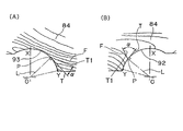
図12は、図11におけるハブ輪81の旋削加工により軌道面90を形成した部分Aの拡大断面を示す。図14(A),(B)は、それぞれ図13に示す外輪84の旋削加工により軌道面92,93を形成した部分A,Bの拡大断面を示す。これら図12,図14において、溝状軌道面90,92,93の曲率の生じた底側の縁部Xから肩側の縁部Yの範囲で、溝曲率中心OからファイバーフローFの断面が析出している点Pまでを直線Lで結び、その直線Lと軌道面の交点Pで接線Tを引き、ファイバーフローFの接線T1との角度αをそれぞれで求めた。この角度を、軌道面に対するファイバーフローFの角度αと定義した。
このファイバーフローの角度αは、加工取り代の大きさ(軌道面の鍛造輪郭形状と旋削仕上げ形状の差)の関係があり、加工取り代が大きい程、ファイバーフローの角度αが大きくなる傾向にあり、ハブ輪81では15°<α<20°であり、外輪84では加工取り代が大きく15°<α<80°範囲でばらつく。
Since it is forged as described above, the fiber flow of the bar material is as shown in FIG. 11 for the hub wheel and the outer ring as shown in FIG. 13 after forging. In the figure, the finished shape of the
FIG. 12 shows an enlarged cross section of a portion A where the
The fiber flow angle α is related to the size of machining allowance (difference between the forged contour shape of the raceway surface and the turning finish shape), and the fiber machining angle α tends to increase as the machining allowance increases. Yes, the
このファイバーフローFは、バー材成形時に生じる材料の流れであり、製鋼時に取り切れない不純物が若干存在し、不純物はファイバーフローFに沿って存在する。一般に正常な潤滑条件下での転がり疲労寿命の起点は、材料中の不純物、特に酸化系の不純物とされており、不純物が大きく長さも長いほど、またその数が多いほど、寿命が低下すると言われている。 The fiber flow F is a material flow that occurs during molding of the bar material, and there are some impurities that cannot be removed during steelmaking, and the impurities exist along the fiber flow F. In general, the starting point of rolling fatigue life under normal lubrication conditions is considered to be impurities in the material, especially oxidation-type impurities, and the longer the impurity is, the longer the length, and the greater the number, the shorter the life. It has been broken.
試験片における試験結果であるが、軌道面に対するファイバーフローの角度と転がり寿命には相関関係があり、角度が大きくなるに従って転がり寿命が低下することが知られている。また、車輪用軸受装置においても、パイプ素材からの製造に比べ、丸棒素材からの製造がファイバーフローの分断を軽微になるとの記載もある(例えば特許文献1)。 Although it is a test result in the test piece, there is a correlation between the angle of the fiber flow with respect to the raceway surface and the rolling life, and it is known that the rolling life decreases as the angle increases. In addition, even in the wheel bearing device, there is a description that the production from the round bar material is lighter than the production from the pipe material (for example, Patent Document 1).
しかし、従来の車輪用軸受装置では、現在求められている転がり疲労寿命は満足するため、基本的にはファイバーフローが考慮されておらず、鍛造の行い易さだけで旋削前の素材形状を決定していた。しかし、鍛造の行い易い旋削前の素材形状は加工取り代が多く、旋削加工の工数を増大させ、その結果、製造コストが増大し、製品の低コスト化に繋がらない。一方、現在十分に転がり寿命は満足しているとは言え、過酷な条件で使用される自動車部品である車輪用軸受装置は、今後さらに厳しい転がり疲労寿命を要求されることが考えられる。上記特許文献1にはパイプ素材の製造より丸棒素材の製造の方がファイバーフローの分断が少なくできる旨の記載はあるが、ファイバーフローの分断を少なくするための工夫や、ファイバーフローの角度に対する考慮はなされていない。また、特許文献1に記載の製造方法は、鍔を有しない外輪についての製造方法であり、ハブ輪や鍔付きの外輪では適用または応用の可否が不明である。
However, conventional wheel bearing devices satisfy the currently required rolling fatigue life, so fiber flow is basically not considered, and the material shape before turning is determined only by the ease of forging. Was. However, the material shape before turning, which is easy to forge, has a large machining allowance and increases the number of turning processes. As a result, the manufacturing cost increases and the cost of the product does not decrease. On the other hand, although the rolling life is sufficiently satisfied at present, it is conceivable that the wheel bearing device which is an automobile part used under severe conditions will be required to have a more severe rolling fatigue life in the future. In the above-mentioned
この発明の目的は、軌道面の加工取り代を削減することにより、軌道面の転がり寿命の向上が図れ、材料重量の削減および切削加工時間の短縮が図れる車輪用軸受装置のハブ輪および外方部材の製造方法を提供することである。 The object of the present invention is to reduce the machining allowance of the raceway surface, thereby improving the rolling life of the raceway surface, reducing the weight of the material and shortening the cutting time, and the hub wheel and the outer side of the wheel bearing device. It is providing the manufacturing method of a member.
この発明の車輪用軸受装置におけるハブ輪の製造方法は、内周に複列の軌道面が形成された外方部材と、この外方部材の軌道面と対向する複列の軌道面を形成した内方部材とを備え、前記内方部材が一つの軌道面と車輪取付フランジが形成されたハブ輪を有し、車体に対して車輪を回転自在に支持する車輪用軸受装置における、前記ハブ輪の製造方法であって、
鋼製のバー材を所定寸法に切断した素材を鍛造する鍛造工程と、鍛造完成後の素材に対して前記軌道面を旋削する旋削工程とを含み、ハブ輪の軌道面に対するファイバーフローの角度が15°以下となることを特徴とする。
この発明の車輪用軸受装置における外方部材の製造方法は、外周にフランジを有し内周に複列の軌道面が形成された外方部材と、この外方部材の軌道面と対向する複列の軌道面を形成した内方部材とを備え、車体に対して車輪を回転自在に支持する車輪用軸受装置における、前記外方部材の製造方法であって、
鋼製のバー材を所定寸法に切断した素材を鍛造する鍛造工程と、鍛造完成後の素材に対して前記軌道面を旋削する旋削工程とを含み、外方部材の軌道面に対するファイバーフローの角度が15°以下となることを特徴とする。
上記各軌道面は、ボールからなる転動体に対応した断面が円弧状の面であっても、また円すいころからなる転動体に対応したテーパ状の面であっても良い。
The hub wheel manufacturing method in the wheel bearing device of the present invention includes an outer member having a double-row raceway surface formed on the inner periphery and a double-row raceway surface facing the raceway surface of the outer member. An inner member, and the inner member has a hub wheel formed with one raceway surface and a wheel mounting flange, and the hub wheel in a wheel bearing device for rotatably supporting a wheel with respect to a vehicle body A manufacturing method of
Including a forging process for forging a material obtained by cutting a steel bar material into a predetermined dimension, and a turning process for turning the raceway surface with respect to the forged material, and the angle of the fiber flow with respect to the raceway surface of the hub ring It is 15 degrees or less.
The method of manufacturing the outer member in the wheel bearing device of the present invention includes an outer member having a flange on the outer periphery and a double-row raceway surface formed on the inner periphery, and a compound facing the raceway surface of the outer member. An inner member formed with a raceway surface of a row, in a wheel bearing device for rotatably supporting a wheel with respect to a vehicle body, the method for manufacturing the outer member,
Including a forging step of forging a material obtained by cutting a steel bar material into a predetermined size, and a turning step of turning the raceway surface with respect to the forged material, and an angle of the fiber flow with respect to the raceway surface of the outer member Is 15 ° or less.
Each of the raceway surfaces may be an arc-shaped surface corresponding to a rolling element made of a ball, or may be a tapered surface corresponding to a rolling element made of a tapered roller.
軌道面に対するファイバーフローの角度と転がり寿命には相関があり、角度が大きくなるに従って転がり寿命が低下する。内方部材、外方部材とも寿命比から見るとファイバーフローの角度を15°以下にすることで、ファイバーフローの角度零とほぼ同等の転がり寿命が得られることが判った。また、ファイバーフローを15°以下にするには軌道面の加工取り代を削減することになり、材料投入重量の削減および切削加工時間の短縮が図れることになる。 There is a correlation between the angle of the fiber flow with respect to the raceway surface and the rolling life, and the rolling life decreases as the angle increases. From the viewpoint of the life ratio of both the inner member and the outer member, it has been found that a rolling life almost equal to the fiber flow angle of zero can be obtained by setting the fiber flow angle to 15 ° or less. Further, when the fiber flow is set to 15 ° or less, the machining allowance of the raceway surface is reduced, and the material input weight and the cutting time can be shortened.
この発明において、ハブ輪または外方部材のいずれかについてのみファイバーフローの角度を上記のように規制しても、そのハブ輪または外方部材について効果が得られるが、ハブ輪および外方部材の両方について、上記のようにファイバーフローの角度を規制することがより好ましい。
また、ハブ輪の軌道面に対するファイバーフローの角度、および外方部材の軌道面に対するファイバーフローの角度は、いずれも、より好ましくは10°以下である。特に、ハブ輪の軌道面に対するファイバーフローの角度を10°以下とすることが好ましい。したがって、例えば、外方部材の軌道面に対するファイバーフローの角度を15°以下とし、ハブ輪の軌道面に対するファイバーフローの角度を10°以下としても良い。
In this invention, even if the angle of the fiber flow is restricted as described above only for either the hub ring or the outer member, the effect is obtained for the hub ring or the outer member. For both, it is more preferable to regulate the angle of the fiber flow as described above.
The angle of the fiber flow with respect to the raceway surface of the hub wheel and the angle of the fiber flow with respect to the raceway surface of the outer member are both preferably 10 ° or less. In particular, the angle of the fiber flow with respect to the raceway surface of the hub wheel is preferably set to 10 ° or less. Therefore, for example, the angle of the fiber flow with respect to the raceway surface of the outer member may be 15 ° or less, and the angle of the fiber flow with respect to the raceway surface of the hub wheel may be 10 ° or less.
この発明の車輪用軸受装置のハブ輪の製造方法は、外方部材が外周にフランジを有しない形式のものにおいても適用される。
すなわち、内周に複列の軌道面が形成された外方部材と、この外方部材の軌道面と対向する複列の軌道面を形成した内方部材と、両軌道面間に介在した複列の転動体と、外方部材と内方部材間の両端の密封装置とを備え、車体に対して車輪を回転自在に支持する車輪用軸受装置において、内方部材が一つの軌道面と車輪取付フランジが形成されたハブ輪を有するものである場合に、このハブ輪の上記軌道面に対するファイバーフローの角度を15°以下としても良い。この場合も、ハブ輪の上記軌道面に対するファイバーフローの角度は、より好ましくは10°以下である。
The hub wheel manufacturing method for a wheel bearing device according to the present invention is also applicable to a type in which the outer member does not have a flange on the outer periphery.
That is, an outer member in which a double row raceway surface is formed on the inner periphery, an inner member in which a double row raceway surface facing the outer member raceway surface is formed, and a composite member interposed between both raceway surfaces. A bearing device for a wheel having a rolling element in a row and a sealing device at both ends between an outer member and an inner member and rotatably supporting the wheel with respect to the vehicle body. In the case where a hub ring having a mounting flange is formed, the angle of the fiber flow with respect to the raceway surface of the hub ring may be 15 ° or less. Also in this case, the angle of the fiber flow with respect to the raceway surface of the hub wheel is more preferably 10 ° or less.
また、この発明は第2世代タイプ等の車輪用軸受装置における外方部材の製造方法においても適用できる。すなわち外周にフランジを有し内周に複列の軌道面が形成された外方部材と、この外方部材の軌道面と対向する複列の軌道面を形成した内方部材と、両軌道面間に介在した複列の転動体と、外方部材と内方部材間の両端の密封装置とを備え、車体に対して車輪を回転自在に支持する車輪用軸受装置において、外方部材の上記軌道面に対するファイバーフローの角度を15°以下としても良い。このファイバーフローの角度も、より好ましくは10°以下である。この車輪用軸受装置の場合、外方部材と内方部材のいずれが回転側としても良い。外方部材が回転側である場合、外方部材の外周のフランジは車輪取付フランジとなり、内方部材が回転側である場合、外方部材の外周のフランジの車体への取付用のフランジとなる。 The present invention can also be applied to a method for manufacturing an outer member in a wheel bearing device of the second generation type or the like. That is, an outer member having a flange on the outer periphery and a double-row raceway surface formed on the inner periphery, an inner member forming a double-row raceway surface facing the raceway surface of the outer member, and both raceway surfaces In a wheel bearing device comprising a double row rolling element interposed therebetween and a sealing device at both ends between the outer member and the inner member, the wheel bearing device rotatably supporting the wheel with respect to the vehicle body, the outer member described above The angle of the fiber flow with respect to the raceway surface may be 15 ° or less. The angle of this fiber flow is also preferably 10 ° or less. In the case of this wheel bearing device, either the outer member or the inner member may be on the rotating side. When the outer member is on the rotating side, the outer peripheral flange of the outer member is a wheel mounting flange, and when the inner member is on the rotating side, the outer peripheral flange of the outer member is a flange for mounting on the vehicle body. .
この発明のハブ輪および外方部材の製造方法を適用する車輪用軸受装置は、内方部材の他方の軌道面が、ハブ輪の端部の外周に嵌合した内輪であっても良い。すなわち、第3世代の車輪用軸受装置であっても良い。 The wheel bearing device to which the hub wheel and the outer member manufacturing method of the present invention is applied may be an inner ring in which the other raceway surface of the inner member is fitted to the outer periphery of the end portion of the hub wheel. That is, it may be a third generation wheel bearing device.
この発明の外方部材の製造方法を適用する車輪用軸受装置は、内方部材が、外方部材に設けられた複列の軌道面に対向する各列の軌道面を有する2個の内輪であっても良い。すなわち、第2世代の車輪用軸受装置であっても良い。この場合に、外輪回転タイプのものであっても、また内輪回転タイプのものであっても良い。
この発明のハブ輪および外方部材の製造方法を適用する車輪用軸受装置は、さらに第4世代の車輪用軸受装置であっても良い。
The wheel bearing device to which the outer member manufacturing method according to the present invention is applied has two inner rings in which the inner member has each row of raceways facing the double row raceway provided on the outer member. There may be. That is, it may be a second generation wheel bearing device. In this case, an outer ring rotating type or an inner ring rotating type may be used.
The wheel bearing device to which the hub wheel and outer member manufacturing method of the present invention is applied may be a fourth generation wheel bearing device.
この発明の車輪用軸受装置におけるハブ輪および外方部材の製造方法において、上記のようにファイバーフローの角度を規定した軌道輪であるハブ輪または外方部材の材質は、軸受鋼、浸炭鋼、または炭素含有量が0.4〜0.8%の炭素鋼製のいずれであっても良い。
これらの材質の鋼材の場合に、上記各軌道面とファイバーフローとの角度の関係が確認された。
In the manufacturing method of the hub wheel and the outer member in the wheel bearing device of the present invention, the material of the hub ring or the outer member that is the race ring that defines the angle of the fiber flow as described above is a bearing steel, a carburized steel, Alternatively, any carbon steel having a carbon content of 0.4 to 0.8% may be used.
In the case of these steel materials, the relationship between the angles of the raceways and the fiber flow was confirmed.
この発明の車輪用軸受装置のハブ輪の製造方法および外方部材の製造方法は、外周に車輪取付フランジを有するハブ輪の軌道面に対するファイバーフローの角度を15°以下とし、または外周にフランジを有する外方部材の軌道面に対するファイバーフローの角度を15°以下とする方法であるため、軌道面の転がり寿命の向上が図れ、かつ軌道面の加工取り代が削減できて、材料投入重量の削減および切削加工時間の短縮が図れるという効果が得られる。 In the wheel bearing device hub wheel manufacturing method and outer member manufacturing method of the present invention, the fiber flow angle with respect to the raceway surface of the hub wheel having the wheel mounting flange on the outer periphery is set to 15 ° or less, or the flange is formed on the outer periphery. Since the fiber flow angle with respect to the raceway surface of the outer member is 15 ° or less, the rolling life of the raceway surface can be improved and the machining allowance of the raceway surface can be reduced, reducing the material input weight. In addition, the effect of shortening the cutting time can be obtained.
この発明の第1の実施形態を図1ないし図7と共に説明する。この実施形態は、第3世代のボールタイプ,駆動輪用で,内輪回転型の車輪用軸受装置に適用した例である。この車輪用軸受装置は、ハブ輪1およびこのハブ輪1のインボード側端の外周に嵌合した内輪2からなる内方部材3と、外方部材4とを備え、車体に対して車輪を回転自在に支持するものである。ハブ輪1は、アウトボード側端に車輪取付用のフランジ5を有しており、フランジ5の周方向複数箇所に形成されたボルト挿通孔7に、車輪取付用のボルト8が圧入されている。また、ハブ輪1は、中央孔1aが貫通した筒状の部材とされている。中央孔1aには、図示しない等速自在継手の外側継手部材の軸部が嵌合している。上記ハブ輪1および内輪2に、複列の軌道面10,11の片方ずつが設けられている。外方部材4は、単独の外輪からなり、外周に車体への取付用のフランジ6を有している。このフランジ6の周方向複数箇所にボルト挿通孔9が形成されている。外方部材4は、ハブ輪1および内輪2の軌道面10,11に対向する複列の軌道面12,13を有し、両列の対向する軌道面10,12間、および軌道面11,13間に転動体14が介在している。軌道面10〜13は、接触角を生じさせる面とされ、この軸受はアンギュラ型のものとされる。転動体14は鋼球等のボールである。これら転動体14は、各列毎に保持器29により保持されている。内方部材3と外方部材4との間の軸受空間における両端は、密封装置15,16により密封されている。密封装置15,16は、例えば外方部材4の内径面に取付けられてシールリップがハブ輪1および内輪2の外径面に接する接触シール等からなる。
A first embodiment of the present invention will be described with reference to FIGS. This embodiment is an example applied to a third-generation ball type and drive wheel and an inner ring rotating type wheel bearing device. This wheel bearing device includes an
ハブ輪1および外方部材4は、いずれも鍛造後に旋削加工して製造される。ハブ輪1および外方部材4の材質は、例えば軸受鋼、または浸炭鋼、または炭素含有量が0.4〜0.8%の炭素鋼とされる。鍛造工程では、ハブ輪1および外方部材4は、図2(A),(B)それぞれ示すように、上記材質のバー材Wを所定寸法に切断し、1100℃前後に加熱して、据え込み、荒成形、仕上成形、および内径抜きを行う。このような鍛造工程により、ハブ輪1は図3に示す形状に、外方部材4は図5に示す形状にそれぞれ加工される。同図において、ハブ輪1および外方部材4の旋削後の仕上げ形状を破線で示した。また、ファイバーフローFを示す曲線を同図の断面中に示した。ハブ輪1は、仕上げ形状おいて、外径面における軌道面10のアウトボード側に円弧状断面形状のシール接触面17が続き、このシール接触面17がフランジ5の側面に続く形状とされている。軌道面10よりもインボード側の外径面部分は、断面が直線状となる円筒面状とされている。外方部材4は、最小径となる円筒面状部分18の両側に断面が円弧状の軌道面12,13がそれぞれ続き、これら軌道面12,13から両端側へ軌道面12,13の最大径よりも僅かに小径の円筒面状部分19,20が続く形状とされている。
Both the
ハブ輪1の軌道面10は図4に拡大して示す形状とされる。外方部材4の軌道面12,13は、それぞれ図6(A),(B)に拡大して示す形状とされる。これら図4に示すように、ハブ輪1の軌道面10に対するファイバーフローFの角度αは、15°以下、より好ましくは10°以下とする。また、図6(A),(B)に示すように、外方部材4の軌道面12,13に対するファイバーフローFの角度αは、いずれも15°以下、より好ましくは10°以下とする。
The
軌道面10,12,13に対するファイバーフローFの角度αは、次のように定義される。すなわち、軌道面10,12,13の曲率の生じた底側の縁部Xから肩側の縁部Yの範囲で、溝曲率中心OからファイバーフローFの断面が析出している点までを直線Lで結び、その直線Lと軌道面10,12,13の交点Pで接線Tを引き、各交点PにおけるファイバーフローFの接線T1と軌道面10,12,13の上記接線Tとが成す角度αを、軌道面に対するファイバーフローの角度αとする。なお、軌道面がテーパ面である場合は、上記接線Tの代わりに、軌道面となるテーパ面の断面に沿う直線、つまりテーパ面の母線を用い、その母線とファイバーフローFの接線T1とが成す角度とする。また、テーパ面がクラウニング形状の場合は、クラウニング曲線の接線をTとする。
The angle α of the fiber flow F with respect to the raceway surfaces 10, 12, and 13 is defined as follows. That is, a straight line extends from the groove curvature center O to the point where the cross section of the fiber flow F is deposited in the range from the bottom edge X to the shoulder edge Y where the curvature of the raceway surfaces 10, 12, and 13 occurs. L is connected by L, and a tangent line T is drawn at the intersection point P between the straight line L and the raceway surfaces 10, 12, 13, and the angle formed by the
上記構成の作用につき説明する。軌道面10,12,13に対するファイバーフローFの角度αと転がり寿命には相関関係があり、角度が大きくなるに従って転がり寿命が低下する。試験、研究の結果、ハブ輪1においては、ファイバーフローFの角度αを15°以下とすることで、また外方部材4においても、ファイバーフローFの角度αを15°以下とすることで、従来に比べて軌道面10,12,13の転がり寿命の向上が顕著に得られることが判った。また、これらのファイバーフローFの角度αは、10°以下とすることで、各軌道面10,12,13の転がり寿命の向上がより一層顕著に得られることが判った。また、ファイバーフローFの角度αを上記のようにハブ輪で15°以下、外方部材4で15°以下と小さくすることは、鍛造完成後の素材形状を極限的に最終形状に近づけることで達成できる。このことは、結果的に、軌道面10,12,13の加工取り代を削減することになり、材料投入重量の削減および切削加工時間の短縮が図れることになる。
The operation of the above configuration will be described. There is a correlation between the angle α of the fiber flow F with respect to the raceway surfaces 10, 12, and 13 and the rolling life, and the rolling life decreases as the angle increases. As a result of the test and research, in the
図7(A)は、棒材から軌道面を削り出した転動疲労試験片での試験結果を示し、軌道面に対するファイバーフローの角度が0°、15°、30°、45°、90°の各場合の結果を示している。同図(B)は、上記各試験片と棒材の軸心方向との関係を示す。同図(A)から、転がり寿命比を見ると、ファイバーフローの角度が0°のとき(理想)の転がり寿命に対してファイバーフローの角度15°以下では略同等の転がり寿命を得られることがわかる。 FIG. 7A shows a test result of a rolling fatigue test piece obtained by cutting the raceway surface from the bar, and the fiber flow angles with respect to the raceway surface are 0 °, 15 °, 30 °, 45 °, 90 °. The result of each case is shown. FIG. 5B shows the relationship between each test piece and the axial direction of the bar. From the figure (A), the rolling life ratio shows that when the fiber flow angle is 0 ° (ideal), the rolling life ratio can be substantially equivalent when the fiber flow angle is 15 ° or less. Recognize.
ファイバーフローの測定方法を説明する。
1.ファイバーフローの析出手順
(1)ハブ輪、外輪をカッターにて軸方向に1箇所切断して試料を作成する。
(2)75〜80℃に加熱した塩酸溶液(塩酸50%+水50%)に試料を投入する。
(3)10〜15分間、試料を浸漬。
(4)試料を取り出し、水洗、乾燥、防錆する。
2.ファイバーフローの判定
上記の手順で析出したファイバーフローの軌道面部の断面写真を取り、倍率2〜5倍で軌道面の底部から肩部の析出ファイバーフローの角度を求める。
A method for measuring the fiber flow will be described.
1. Fiber Flow Precipitation Procedure (1) A sample is prepared by cutting the hub wheel and outer ring in one axial direction with a cutter.
(2) A sample is put into a hydrochloric acid solution (hydrochloric acid 50% + water 50%) heated to 75 to 80 ° C.
(3) Immerse the sample for 10-15 minutes.
(4) Take out the sample, wash with water, dry and rust.
2. Determination of Fiber Flow Take a cross-sectional photograph of the raceway surface portion of the fiber flow deposited by the above procedure, and determine the angle of the deposited fiber flow from the bottom of the raceway surface to the shoulder at a magnification of 2 to 5.
なお、上記実施形態は、ハブ輪1に内輪2を圧入またはボルト(図示せず)で固定する形式のものとしたが、図8(A)に示すように、ハブ輪1のインボード側端部に設けた加締部21で内輪2をハブ輪1に固定するものとしても良い。また、図8(B)に示すように、従動輪用の車輪用軸受装置としても良い。同図の車輪用軸受装置は、ハブ輪1が中央孔1aを有しないものとされている他は、図8(A)の例と同じである。
In the above embodiment, the
また、上記各実施形態は、いずれも第3世代の車輪用軸受装置に適用した場合につき説明したが、この発明は第2世代や第4世代の車輪用軸受装置に適用することもできる。 Moreover, although each said embodiment demonstrated as the case where all were applied to the 3rd generation wheel bearing apparatus, this invention can also be applied to the 2nd generation or the 4th generation wheel bearing apparatus.
図9(A)は、第2世代で外輪回転タイプとした例である。この車輪用軸受装置は、単独の外輪からなる外方部材30が内周に複列の軌道面31,32を有し、これら複列の軌道面31,32に対向する軌道面33,34を有する内方部材35と、両列の対向する軌道面31,33間、軌道面32,34間に介在した転動体36とを備えている。内方部材35は、各列毎の軌道面33,34を有する内輪35A,35Bを並べたものとされている。この第2世代の外輪回転タイプの場合、外方部材30の外周アウトボード側に車輪取付フランジ5Aが形成されている。この例においては、外方部材30の軌道面31,32に対するファイバーフロー(図示せず)の角度を15°以下とし、より好ましくは10°以下としている。
FIG. 9A is an example of the outer ring rotation type in the second generation. In this wheel bearing device, an
図9(B)は、第2世代で内輪回転タイプとした例である。この車輪用軸受装置は、フランジ6Aを有する外方部材4Aに設けられた複列の軌道面41,42に対向する複列の軌道面43,44を有する内方部材45と、両列の対向する軌道面41,43間、軌道面42,44間に介在した転動体46とを備える。内方部材45は、各列毎の軌道面43,44を有する内輪45A,45Bを並べたものとされている。この実施形態では、外方部材4Aの軌道面41,42に対するファイバーフロー(図示せず)の角度が15°以下とされ、より好ましくは10°以下とされる。この第2世代の内輪回転タイプの場合、内輪45A,45Bは図示しない車輪取付フランジを有するハブ輪の外周に嵌合されるのが一般的な使われ方である。
FIG. 9B is an example of the inner ring rotation type in the second generation. This wheel bearing device includes an
図10は、第4世代の車輪用軸受装置に適用した例である。この車輪用軸受装置は、車輪取付用のフランジ5Bを有するハブ輪1B、およびこのハブ輪1Bの内周に軸部51aが嵌合した等速ジョイント外輪51により内方部材52が構成され、ハブ輪1Bおよび等速ジョイント外輪51に軌道面53,54が形成される。外方部材4Bは外周に車体への取付用のフランジ6Bを有し、内周に上記各軌道面53,54と対向する軌道面55,56が形成されている。対向する各軌道面53,55間および軌道面54,56間に、転動体57が介在している。この実施形態では、外方部材4Bの軌道面55,56に対するファイバーフロー(図示せず)の角度が15°以下とされている。また、ハブ輪1Bの軌道面53に対するファイバーフロー(図示せず)の角度が10°以下とされている。なお、ハブ輪1Bの軌道面53に対するファイバーフロー(図示せず)の角度は15°以下であれば良く、また外方部材4Bの軌道面55,56に対するファイバーフロー(図示せず)の角度は、より好ましくは10°以下である。
FIG. 10 shows an example applied to a fourth-generation wheel bearing device. In this wheel bearing device, an
なお、上記各実施形態は、いずれもボールタイプの車輪用軸受装置としたが、この発明は、円すいころ軸受タイプの車輪用軸受装置におけるハブ輪および外方部材の製造方法にも適用することができる。
またこの発明において、軌道面に対するファイバーフローの角度を15°以下としたという要件、および10°以下としたという要件は、いずれも実質上全周において満たされていれば良い。
Each of the above embodiments is a ball type wheel bearing device, but the present invention can also be applied to a method of manufacturing a hub wheel and an outer member in a tapered roller bearing type wheel bearing device. it can.
In the present invention, both the requirement that the angle of the fiber flow with respect to the raceway surface is 15 ° or less, and the requirement that the angle of 10 ° or less are satisfied may be satisfied substantially over the entire circumference.
1…ハブ輪
2…内輪
3…内方部材
4…外方部材
5…フランジ
6…フランジ
10,11…軌道面
12,13…軌道面
14…転動体
15,16…密封装置
F…ファイバーフロー
α…角度
DESCRIPTION OF
Claims (2)
鋼製のバー材を所定寸法に切断した素材を鍛造する鍛造工程と、鍛造完成後の素材に対して前記軌道面を旋削する旋削工程とを含み、ハブ輪の軌道面に対するファイバーフローの角度が15°以下となることを特徴とする車輪用軸受装置のハブ輪の製造方法。 An outer member having a double-row raceway surface formed on the inner periphery, and an inner member having a double-row raceway surface facing the raceway surface of the outer member. A method of manufacturing the hub wheel in a wheel bearing device having a hub wheel formed with a surface and a wheel mounting flange, and rotatably supporting the wheel with respect to the vehicle body,
Including a forging process for forging a material obtained by cutting a steel bar material into a predetermined dimension, and a turning process for turning the raceway surface with respect to the forged material, and the angle of the fiber flow with respect to the raceway surface of the hub ring The manufacturing method of the hub ring of the wheel bearing apparatus characterized by being 15 degrees or less.
鋼製のバー材を所定寸法に切断した素材を鍛造する鍛造工程と、鍛造完成後の素材に対して前記軌道面を旋削する旋削工程とを含み、外方部材の軌道面に対するファイバーフローの角度が15°以下となることを特徴とする車輪用軸受装置の外方部材の製造方法。
An outer member having a flange on the outer periphery and having a double-row raceway surface formed on the inner periphery, and an inner member having a double-row raceway surface facing the raceway surface of the outer member, In the wheel bearing device for rotatably supporting the wheel, a method for manufacturing the outer member,
Including a forging step of forging a material obtained by cutting a steel bar material into a predetermined size, and a turning step of turning the raceway surface with respect to the forged material, and an angle of the fiber flow with respect to the raceway surface of the outer member The manufacturing method of the outward member of the bearing apparatus for wheels characterized by becoming 15 degrees or less.
Priority Applications (1)
| Application Number | Priority Date | Filing Date | Title |
|---|---|---|---|
| JP2007010015A JP2007147079A (en) | 2007-01-19 | 2007-01-19 | Method of manufacturing hub ring and outward member of wheel bearing device |
Applications Claiming Priority (1)
| Application Number | Priority Date | Filing Date | Title |
|---|---|---|---|
| JP2007010015A JP2007147079A (en) | 2007-01-19 | 2007-01-19 | Method of manufacturing hub ring and outward member of wheel bearing device |
Related Parent Applications (1)
| Application Number | Title | Priority Date | Filing Date |
|---|---|---|---|
| JP2003317862A Division JP2005083513A (en) | 2003-09-10 | 2003-09-10 | Wheel bearing device |
Publications (1)
| Publication Number | Publication Date |
|---|---|
| JP2007147079A true JP2007147079A (en) | 2007-06-14 |
Family
ID=38208700
Family Applications (1)
| Application Number | Title | Priority Date | Filing Date |
|---|---|---|---|
| JP2007010015A Pending JP2007147079A (en) | 2007-01-19 | 2007-01-19 | Method of manufacturing hub ring and outward member of wheel bearing device |
Country Status (1)
| Country | Link |
|---|---|
| JP (1) | JP2007147079A (en) |
Cited By (3)
| Publication number | Priority date | Publication date | Assignee | Title |
|---|---|---|---|---|
| US8393987B2 (en) | 2008-10-22 | 2013-03-12 | Ntn Corporation | Chain tensioner |
| JP2015048915A (en) * | 2013-09-03 | 2015-03-16 | 日本精工株式会社 | Wheel supporting rolling bearing unit and method of manufacturing hub for the same |
| WO2015050258A1 (en) * | 2013-10-04 | 2015-04-09 | Ntn株式会社 | Production method for outer member for wheel bearing device |
Citations (4)
| Publication number | Priority date | Publication date | Assignee | Title |
|---|---|---|---|---|
| JPS60170547A (en) * | 1984-02-13 | 1985-09-04 | Ntn Toyo Bearing Co Ltd | Production of bearing race |
| JPH0566215B2 (en) * | 1988-06-17 | 1993-09-21 | Kotani Tanko Kk | |
| JPH06170479A (en) * | 1992-12-08 | 1994-06-21 | Nippon Seiko Kk | Manufacture of outer ring of ball bearing |
| JP2003090350A (en) * | 2001-09-17 | 2003-03-28 | Ntn Corp | Fixing structure of bearing for wheel and bearing for wheel |
-
2007
- 2007-01-19 JP JP2007010015A patent/JP2007147079A/en active Pending
Patent Citations (4)
| Publication number | Priority date | Publication date | Assignee | Title |
|---|---|---|---|---|
| JPS60170547A (en) * | 1984-02-13 | 1985-09-04 | Ntn Toyo Bearing Co Ltd | Production of bearing race |
| JPH0566215B2 (en) * | 1988-06-17 | 1993-09-21 | Kotani Tanko Kk | |
| JPH06170479A (en) * | 1992-12-08 | 1994-06-21 | Nippon Seiko Kk | Manufacture of outer ring of ball bearing |
| JP2003090350A (en) * | 2001-09-17 | 2003-03-28 | Ntn Corp | Fixing structure of bearing for wheel and bearing for wheel |
Cited By (4)
| Publication number | Priority date | Publication date | Assignee | Title |
|---|---|---|---|---|
| US8393987B2 (en) | 2008-10-22 | 2013-03-12 | Ntn Corporation | Chain tensioner |
| JP2015048915A (en) * | 2013-09-03 | 2015-03-16 | 日本精工株式会社 | Wheel supporting rolling bearing unit and method of manufacturing hub for the same |
| WO2015050258A1 (en) * | 2013-10-04 | 2015-04-09 | Ntn株式会社 | Production method for outer member for wheel bearing device |
| JP2015071183A (en) * | 2013-10-04 | 2015-04-16 | Ntn株式会社 | Manufacturing method of outer member of wheel bearing device |
Similar Documents
| Publication | Publication Date | Title |
|---|---|---|
| JP2005083513A (en) | Wheel bearing device | |
| JP6523677B2 (en) | Method of manufacturing hub wheel and inner member of wheel bearing device | |
| US20100239202A1 (en) | Double-row angular bearing, bearing device for wheel, method of producing outer race, and method of producing inner race | |
| CN101743133B (en) | Wheel bearing apparatus for a vehicle | |
| JPH11129703A (en) | Rolling bearing unit for wheel supporting | |
| US10137541B2 (en) | Method for manufacturing bearing ring member | |
| JP2002250358A (en) | Rolling bearing unit for supporting wheel | |
| JP2006220221A (en) | Rolling bearing, bearing unit | |
| JP2007147079A (en) | Method of manufacturing hub ring and outward member of wheel bearing device | |
| JP2007016959A (en) | Method of manufacturing outer ring of rolling bearing unit for supporting wheel | |
| JP4536086B2 (en) | Wheel bearing device and manufacturing method thereof | |
| JP4572864B2 (en) | Wheel support bearing unit outer member, wheel support bearing unit | |
| JP2008173995A (en) | Bearing device for wheel | |
| JP5166757B2 (en) | Wheel bearing and wheel bearing device provided with the same | |
| JP2008162568A (en) | Wheel supporting double row rolling bearing unit, and manufacturing method thereof | |
| JP2008101685A (en) | Bearing device for wheel and its manufacturing method | |
| JP4561389B2 (en) | Outside member of bearing unit | |
| JP6171741B2 (en) | Manufacturing method of wheel-supporting rolling bearing unit and manufacturing method of wheel-supporting rolling bearing unit hub | |
| JP5252834B2 (en) | Manufacturing method of wheel bearing device | |
| JP6224402B2 (en) | Method for manufacturing outer member of wheel bearing device | |
| JP2007100715A (en) | Bearing device for vehicle | |
| JP3601537B2 (en) | Rolling bearing unit for wheel support | |
| JP2023043696A (en) | Wheel bearing device | |
| EP2684709A1 (en) | Shaft member for rolling bearing device for wheel | |
| JP2023059592A (en) | Method for manufacturing hub unit bearing |
Legal Events
| Date | Code | Title | Description |
|---|---|---|---|
| A131 | Notification of reasons for refusal |
Free format text: JAPANESE INTERMEDIATE CODE: A131 Effective date: 20091027 |
|
| A521 | Written amendment |
Free format text: JAPANESE INTERMEDIATE CODE: A523 Effective date: 20091225 |
|
| A131 | Notification of reasons for refusal |
Free format text: JAPANESE INTERMEDIATE CODE: A131 Effective date: 20100406 |
|
| A521 | Written amendment |
Free format text: JAPANESE INTERMEDIATE CODE: A523 Effective date: 20100602 |
|
| A131 | Notification of reasons for refusal |
Free format text: JAPANESE INTERMEDIATE CODE: A131 Effective date: 20100914 |
|
| A02 | Decision of refusal |
Free format text: JAPANESE INTERMEDIATE CODE: A02 Effective date: 20110222 |