JP2007147064A - Bearing device for wheel - Google Patents
Bearing device for wheel Download PDFInfo
- Publication number
- JP2007147064A JP2007147064A JP2006214124A JP2006214124A JP2007147064A JP 2007147064 A JP2007147064 A JP 2007147064A JP 2006214124 A JP2006214124 A JP 2006214124A JP 2006214124 A JP2006214124 A JP 2006214124A JP 2007147064 A JP2007147064 A JP 2007147064A
- Authority
- JP
- Japan
- Prior art keywords
- wheel
- rolling surface
- balls
- bearing device
- ball
- Prior art date
- Legal status (The legal status is an assumption and is not a legal conclusion. Google has not performed a legal analysis and makes no representation as to the accuracy of the status listed.)
- Pending
Links
Images


Abstract
Description
本発明は、自動車等の車輪を回転自在に支承する車輪用軸受装置、特に、組立時におけるボール傷の発生を抑制して軸受の音響特性を高めると共に、高剛性化と軸受の長寿命化を図った車輪用軸受装置に関するものである。 The present invention relates to a wheel bearing device for rotatably supporting a wheel of an automobile or the like, and in particular, to improve the acoustic characteristics of the bearing by suppressing the occurrence of ball scratches during assembly, and to increase the rigidity and the life of the bearing. The present invention relates to the wheel bearing device shown.
従来から自動車等の車輪を支持する車輪用軸受装置は、車輪を取り付けるためのハブ輪を転がり軸受を介して回転自在に支承するもので、駆動輪用と従動輪用とがある。構造上の理由から、駆動輪用では内輪回転方式が、従動輪用では内輪回転と外輪回転の両方式が一般的に採用されている。この車輪用軸受装置には、所望の軸受剛性を有し、ミスアライメントに対しても耐久性を発揮すると共に、燃費向上の観点から回転トルクが小さい複列アンギュラ玉軸受が多用されている。この複列アンギュラ玉軸受は、固定輪と回転輪との間に複数のボールを介在させ、このボールに所定の接触角を付与して固定輪および回転輪に接触させている。 2. Description of the Related Art Conventionally, a wheel bearing device for supporting a wheel of an automobile or the like is such that a hub wheel for mounting a wheel is rotatably supported via a rolling bearing, and there are a drive wheel and a driven wheel. For structural reasons, an inner ring rotation method is generally used for driving wheels, and an inner ring rotation method and an outer ring rotation method are generally used for driven wheels. As the wheel bearing device, a double-row angular ball bearing having a desired bearing rigidity, exhibiting durability against misalignment, and having a small rotational torque from the viewpoint of improving fuel efficiency is often used. In this double row angular contact ball bearing, a plurality of balls are interposed between a fixed ring and a rotating ring, and a predetermined contact angle is given to the balls so as to contact the fixed ring and the rotating ring.
また、車輪用軸受装置には、懸架装置を構成するナックルとハブ輪との間に複列アンギュラ玉軸受等からなる車輪用軸受を嵌合させた第1世代と称される構造から、外方部材の外周に直接車体取付フランジまたは車輪取付フランジが形成された第2世代構造、また、ハブ輪の外周に一方の内側転走面が直接形成された第3世代構造、あるいは、ハブ輪と等速自在継手の外側継手部材の外周にそれぞれ内側転走面が直接形成された第4世代構造とに大別されている。 Further, the wheel bearing device has a structure called a first generation in which a wheel bearing composed of a double row angular ball bearing or the like is fitted between a knuckle and a hub wheel constituting a suspension device. Second generation structure in which body mounting flange or wheel mounting flange is formed directly on the outer periphery of the member, third generation structure in which one inner rolling surface is directly formed on the outer periphery of the hub wheel, or hub wheel, etc. It is roughly classified into a fourth generation structure in which the inner rolling surface is directly formed on the outer periphery of the outer joint member of the speed universal joint.
こうした車輪用軸受装置において、従来は両列の軸受が同一仕様のため、静止時には充分な剛性を有するが、車両の旋回時には必ずしも最適な剛性が得られていない。すなわち、静止時の車重は複列の転がり軸受の略中央に作用するように車輪との位置関係が決められているが、旋回時には、旋回方向の反対側(右旋回の場合は車両の左側)の車軸に、より大きなラジアル荷重やアキシアル荷重が負荷される。したがって、旋回時には、インナー側の軸受列よりもアウター側の軸受列の剛性を高めることが有効とされている。そこで、装置を大型化させることなく高剛性化を図った車輪用軸受装置として、図7に示すものが知られている。 In such a wheel bearing device, conventionally, both rows of bearings have the same specification, so that they have sufficient rigidity when stationary, but the optimum rigidity is not always obtained when the vehicle turns. That is, the position of the vehicle weight when stationary is determined so that it acts on the approximate center of the double row rolling bearing, but when turning, the opposite side of the turning direction (when turning right, the vehicle Larger radial load or axial load is applied to the left axle. Therefore, at the time of turning, it is effective to increase the rigidity of the outer bearing row rather than the inner bearing row. Then, what is shown in FIG. 7 is known as a wheel bearing apparatus which achieved high rigidity without enlarging an apparatus.
この車輪用軸受装置50は、外周にナックル(図示せず)に取り付けられるための車体取付フランジ51cを一体に有し、内周に複列の外側転走面51a、51bが形成された外方部材51と、一端部に車輪(図示せず)を取り付けるための車輪取付フランジ53を一体に有し、外周に複列の外側転走面51a、51bに対向する一方の内側転走面52aと、この内側転走面52aから軸方向に延びる小径段部52bが形成されたハブ輪52、およびこのハブ輪52の小径段部52bに外嵌され、複列の外側転走面51a、51bに対向する他方の内側転走面54aが形成された内輪54からなる内方部材55と、これら両転走面間に収容された複列のボール56、57と、これら複列のボール56、57を転動自在に保持する保持器58、59とを備えた複列アンギュラ玉軸受で構成されている。
This
内輪54は、ハブ輪52の小径段部52bを径方向外方に塑性変形させて形成した加締部52cによって軸方向に固定されている。そして、外方部材51と内方部材55との間に形成される環状空間の開口部にシール60、61が装着され、軸受内部に封入された潤滑グリースの漏洩と、外部から軸受内部に雨水やダスト等が侵入するのを防止している。
The
ここで、アウター側のボール56のピッチ円直径D1が、インナー側のボール57のピッチ円直径D2よりも大径に設定されている。これに伴い、ハブ輪52の内側転走面52aが内輪54の内側転走面54aよりも拡径され、あわせて外方部材51のアウター側の外側転走面51aがインナー側の外側転走面51bよりも拡径されている。そして、アウター側のボール56がインナー側のボール57よりも多数収容されている。このように、各ピッチ円直径D1、D2をD1>D2に設定することにより、車両の静止時だけでなく旋回時においても剛性が向上し、車輪用軸受装置50の長寿命化を図ることができる。
然しながら、こうした従来の車輪用軸受装置50の場合、アウター側のボール56のピッチ円直径D1がインナー側のボール57のピッチ円直径D2よりも大径に設定されているため、ハブ輪52において、アウター側の内側転走面52aと、内輪54が圧入される小径段部52bとの間には段部63が形成される。すなわち、少なくとも両ピッチ円直径D1、D2の径差分の段差(D1−D2)/2からなる段部63ができるため、軸受の組立工程において、外方部材51のアウター側の外側転走面51aに仮組みされたアウター側のボール56が、内側転走面52aのカウンタ部62をはじめハブ輪52の段部63に接触する恐れがあった。
However, in such a conventional wheel bearing
また、保持器58、59によって保持された複列のボール56、57を外方部材51の複列の外側転走面51a、51bに仮組みする際においても、ボール56、57が外側転走面51a、51bのカウンタ部64、65に擦れながら挿入されるため、カウンタ部64、65の旋削目がボール56、57に転写したり、あるいは、カウンタ部64、65の角部にボール56、57が接触することにより、ボール56、57に微小な傷が付く恐れがあった。このように、組立工程において、ボール56、57に微小な傷が発生すると、軸受の音響特性が低下するだけでなく短寿命の原因となる恐れがあるため、組立工程はおのずと慎重にならざるを得なく、量産性を阻害する要因の一つとなっていた。
Further, when the double rows of
本発明は、このような事情に鑑みてなされたもので、装置の高剛性化を図ると共に、組立工程等におけるボール傷の発生を抑制し、軸受の長寿命化を図った車輪用軸受装置を提供することを目的としている。 SUMMARY OF THE INVENTION The present invention has been made in view of such circumstances, and provides a wheel bearing device that increases the rigidity of the device and suppresses the occurrence of ball scratches in the assembly process and the like, thereby extending the life of the bearing. It is intended to provide.
係る目的を達成すべく、本発明のうち請求項1記載の発明は、内周に複列の外側転走面が形成された外方部材と、内周に前記複列の外側転走面に対向する複列の内側転走面が設けられた内方部材と、この内方部材と前記外方部材の両転走面間に転動自在に収容された複列のボール群とを備えた車輪用軸受装置において、前記複列のボール群のうち前記車輪取付フランジに近い側のボール群のピッチ円直径が、前記車輪取付フランジに遠い側のボール群のピッチ円直径よりも大径に設定されると共に、前記カウンタ部が滑らかな円弧状に形成され、前記カウンタ部の内周面の表面粗さが3.2Ra以下に規制されている。
In order to achieve such an object, the invention according to
このように、複列アンギュラ玉軸受で構成された車輪用軸受装置において、複列のボール群のうち車輪取付フランジに近い側のボール群のピッチ円直径が、車輪取付フランジに遠い側のボール群のピッチ円直径よりも大径に設定されると共に、カウンタ部が滑らかな円弧状に形成され、カウンタ部の内周面の表面粗さが3.2Ra以下に規制されているので、組立時のボール接触傷やボール振動による打ち傷等を抑制することができ、軸受の音響特性を向上させると共に、製品品質の信頼性を向上させることができる。したがって、装置の高剛性化を図ると共に、軸受の長寿命化を図った車輪用軸受装置を提供することができる。 In this way, in the wheel bearing device constituted by the double row angular ball bearing, the pitch circle diameter of the ball group closer to the wheel mounting flange in the double row ball group has a ball group far from the wheel mounting flange. Since the counter portion is formed in a smooth arc shape and the surface roughness of the inner peripheral surface of the counter portion is regulated to 3.2 Ra or less, Ball contact flaws, ball hitting due to ball vibration, and the like can be suppressed, and the acoustic characteristics of the bearing can be improved and the reliability of product quality can be improved. Therefore, it is possible to provide a wheel bearing device in which the rigidity of the device is increased and the life of the bearing is extended.
好ましくは、請求項2に記載の発明のように、前記複列のボールの外径が同じで、前記車輪取付フランジに近い側のボール群の個数が前記車輪取付フランジに遠い側のボール群の個数よりも多く設定されていれば、高剛性化を図りながら軸受寿命を確保することができる。
Preferably, as in the invention according to
また、請求項3に記載の発明のように、前記各転走面の肩部の角部が面潰しされて滑らかな円弧状に形成されていれば、各転走面とボールとの接触による接触楕円が肩部にかかってもエッジロードが発生するのを抑制することができ、軸受の長寿命化を図ることができる。
Moreover, if the corner | angular part of the shoulder part of each said rolling surface is crushed and formed in smooth arc shape like invention of
また、請求項4に記載の発明のように、前記外側転走面の肩部とカウンタ部の内周面が、熱処理後に総型砥石によって前記転走面と同時研削により形成されていれば、繋ぎ部を一層滑らかにすると共に、内周面の表面粗さを向上させ、ボールがこの内周面に擦れて挿入されてもボールに転写傷が付くのを抑制することができる。
Further, as in the invention according to
また、請求項5に記載の発明は、前記内方部材が、一端部に車輪取付フランジを一体に有し、外周に前記複列の外側転走面に対向する一方の内側転走面と、この内側転走面から軸方向に延びる小径段部が形成されたハブ輪、およびこのハブ輪の小径段部に圧入され、外周に前記複列の外側転走面に対向する他方の内側転走面が形成された内輪からなると共に、前記ハブ輪の前記車輪取付フランジ側の端部にすり鉢状の凹所が形成され、この凹所の深さが少なくとも前記ハブ輪の内側転走面の溝底付近とされ、前記ハブ輪の外郭形状が当該凹所に対応して略均一な肉厚となるように形成されているので、装置の軽量・コンパクト化と高剛性化という相反する課題を同時に解決することができる。
Further, in the invention according to
本発明に係る車輪用軸受装置は、内周に複列の外側転走面が形成された外方部材と、
内周に前記複列の外側転走面に対向する複列の内側転走面が設けられた内方部材と、この内方部材と前記外方部材の両転走面間に転動自在に収容された複列のボール群とを備えた車輪用軸受装置において、前記複列のボール群のうち前記車輪取付フランジに近い側のボール群のピッチ円直径が、前記車輪取付フランジに遠い側のボール群のピッチ円直径よりも大径に設定されると共に、前記カウンタ部が滑らかな円弧状に形成され、前記カウンタ部の内周面の表面粗さが3.2Ra以下に規制されているので、組立時のボール接触傷やボール振動による打ち傷等を抑制することができ、軸受の音響特性を向上させると共に、製品品質の信頼性を向上させることができる。したがって、装置の高剛性化を図ると共に、軸受の長寿命化を図った車輪用軸受装置を提供することができる。
The wheel bearing device according to the present invention, an outer member having a double row outer rolling surface formed on the inner periphery,
An inner member provided with a double row inner rolling surface facing the outer rolling surface of the double row on the inner periphery, and freely rollable between both rolling surfaces of the inner member and the outer member In a wheel bearing device including a double row ball group accommodated, a pitch circle diameter of a ball group closer to the wheel mounting flange in the double row ball group is closer to the wheel mounting flange. The diameter is set larger than the pitch circle diameter of the ball group, the counter portion is formed in a smooth arc shape, and the surface roughness of the inner peripheral surface of the counter portion is regulated to 3.2 Ra or less. In addition, it is possible to suppress ball contact damage during assembly and damage due to ball vibration, and the acoustic characteristics of the bearing can be improved, and the reliability of product quality can be improved. Therefore, it is possible to provide a wheel bearing device in which the rigidity of the device is increased and the life of the bearing is extended.
外周にナックルに取り付けられるための車体取付フランジを一体に有し、内周に複列の外側転走面が形成された外方部材と、一端部に車輪を取り付けるための車輪取付フランジを一体に有し、外周に前記複列の外側転走面に対向する一方の内側転走面と、この内側転走面から軸方向に延びる小径段部が形成されたハブ輪、およびこのハブ輪の小径段部に圧入され、外周に前記複列の外側転走面に対向する他方の内側転走面が形成された内輪からなる内方部材と、この内方部材と前記外方部材の両転走面間に転動自在に収容された複列のボール群とを備え、前記小径段部の端部を径方向外方に塑性変形させて形成した加締部により前記内輪がハブ輪に対して軸方向に固定された車輪用軸受装置において、前記複列のボール群のうち前記車輪取付フランジに近い側のボール群のピッチ円直径が、前記車輪取付フランジに遠い側のボール群のピッチ円直径よりも大径に設定され、前記複列のボールの外径が同じで、前記車輪取付フランジに近い側のボール群の個数が前記車輪取付フランジに遠い側のボール群の個数よりも多く設定されると共に、前記外側転走面の肩部とカウンタ部が、熱処理後に総型砥石によって前記各転走面と同時研削され、角部が面潰しされて滑らかな円弧状に形成され、前記カウンタ部の内周面の表面粗さが3.2Ra以下に規制されている。 A body mounting flange for mounting to the knuckle on the outer periphery is integrated, an outer member with a double row outer raceway formed on the inner periphery, and a wheel mounting flange for mounting the wheel on one end is integrated. A hub wheel having one inner rolling surface facing the outer rolling surface of the double row on the outer periphery, a small diameter step portion extending in the axial direction from the inner rolling surface, and a small diameter of the hub wheel An inner member consisting of an inner ring that is press-fitted into a stepped portion and has the other inner rolling surface facing the outer rolling surface of the double row on the outer periphery, and both rolling of the inner member and the outer member A plurality of ball groups accommodated in a rollable manner between the surfaces, and the inner ring is connected to the hub ring by a caulking portion formed by plastically deforming an end of the small diameter step portion radially outward. In the wheel bearing device fixed in the axial direction, the wheel mounting in the double row ball group. The pitch circle diameter of the ball group closer to the lunge is set to be larger than the pitch circle diameter of the ball group farther from the wheel mounting flange, the outer diameter of the double row balls is the same, and the wheel mounting The number of ball groups closer to the flange is set to be larger than the number of ball groups farther from the wheel mounting flange, and the shoulder and counter portion of the outer rolling surface are subjected to the above-mentioned grinding wheel after heat treatment. Simultaneously with each rolling surface, the corners are flattened to form a smooth arc shape, and the surface roughness of the inner peripheral surface of the counter unit is regulated to 3.2 Ra or less.
以下、本発明の実施の形態を図面に基づいて詳細に説明する。
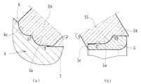
図1は、本発明に係る車輪用軸受装置の第1の実施形態を示す縦断面図、図2は、図1のアウター側の軸受列を示す要部拡大図、図3は、図1のインナー側の軸受列を示す要部拡大図、図4は、熱処理後の外方部材の研削加工を示す説明図、図5(a)は、熱処理後のハブ輪の研削加工を示す説明図、(b)は、熱処理後の内輪の研削加工を示す説明図である。なお、以下の説明では、車両に組み付けた状態で車両の外側寄りとなる側をアウター側(図面左側)、中央寄り側をインナー側(図面右側)という。
Hereinafter, embodiments of the present invention will be described in detail with reference to the drawings.
FIG. 1 is a longitudinal sectional view showing a first embodiment of a wheel bearing device according to the present invention, FIG. 2 is an enlarged view of a main part showing a bearing row on the outer side of FIG. 1, and FIG. FIG. 4 is an explanatory view showing grinding of the outer member after heat treatment, FIG. 5 (a) is an explanatory view showing grinding of the hub wheel after heat treatment, (B) is explanatory drawing which shows the grinding process of the inner ring | wheel after heat processing. In the following description, the side closer to the outer side of the vehicle in a state assembled to the vehicle is referred to as the outer side (left side in the drawing), and the side closer to the center is referred to as the inner side (right side in the drawing).
この車輪用軸受装置は第3世代と呼称される従動輪用であって、内方部材1と外方部材2、および両部材1、2間に転動自在に収容された複列のボール3、3群とを備えている。内方部材1は、ハブ輪4と、このハブ輪4に所定のシメシロを介して圧入された内輪5とからなる。ハブ輪4は、一端部に車輪(図示せず)を取り付けるための車輪取付フランジ6を一体に有し、外周に一方(アウター側)の内側転走面4aと、この内側転走面4aから軸方向に延びる軸状部7を介して小径段部4bが形成されている。車輪取付フランジ6にはハブボルト6aが周方向等配に植設されると共に、これらハブボルト6a間には円孔6bが形成されている。この円孔6bは軽量化に寄与できるだけでなく、装置の組立・分解工程において、レンチ等の締結治具をこの円孔6bから挿入することができ作業を簡便化することができる。
This wheel bearing device is for a driven wheel called a third generation, and includes an
内輪5は、外周に他方(インナー側)の内側転走面5aが形成され、ハブ輪4の小径段部4bに圧入されると共に、この小径段部4bの端部を塑性変形させて形成した加締部4cによって軸方向に固定されている。なお、内輪5はSUJ2等の高炭素クロム鋼で形成され、ズブ焼入れによって芯部まで58〜64HRCの範囲に硬化処理されている。
The
ハブ輪4はS53C等の炭素0.40〜0.80wt%を含む中炭素鋼で形成され、内側転走面4aをはじめ、車輪取付フランジ6のインナー側の基部6cから小径段部4bに亙って高周波焼入れによって表面硬さを58〜64HRCの範囲に硬化処理されている。なお、加締部4cは鍛造加工後の表面硬さのままとされている。これにより、車輪取付フランジ6に負荷される回転曲げ荷重に対して充分な機械的強度を有し、内輪5の嵌合部となる小径段部4bの耐フレッティング性が向上すると共に、微小なクラック等の発生がなく加締部4cの塑性加工をスムーズに行うことができる。
The
外方部材2は、外周にナックル(図示せず)に取り付けられるための車体取付フランジ2cを一体に有し、内周にハブ輪4の内側転走面4aに対向するアウター側の外側転走面2aと、内輪5の内側転走面5aに対向するインナー側の外側転走面2bが一体に形成されている。これら両転走面間に複列のボール3、3が収容され、保持器9、10によって転動自在に保持されている。この外方部材2はS53C等の炭素0.40〜0.80wt%を含む中炭素鋼で形成され、複列の外側転走面2a、2bが高周波焼入れによって表面硬さを58〜64HRCの範囲に硬化処理されている。そして、外方部材2と内方部材1との間に形成される環状空間のアウター側端部にはシール11が装着され、インナー側端部(内輪5)には車輪の回転速度を検出するための磁気エンコーダ12が固定されると共に、外方部材2の開口端部を覆うキャップ(図示せず)が装着されている。これらシール11およびキャップによって、軸受内部に封入されたグリースの外部への漏洩と、外部から雨水やダスト等が軸受内部に侵入するのを防止している。なお、ここでは、従動輪側の第3世代構造を例示したが、本発明に係る車輪用軸受装置はこれに限らず、第1および第2世代、あるいは第4世代構造であっても良い。
The
ここで、本実施形態では、アウター側のボール3群のピッチ円直径PCDoがインナー側のボール3群のピッチ円直径PCDiよりも大径に設定されている。そして、複列のボール3、3の外径dは同じであるが、このピッチ円直径PCDo、PCDiの違いにより、アウター側のボール3群の個数がインナー側のボール3群の個数よりも多く設定されている。
Here, in the present embodiment, the pitch circle diameter PCDo of the outer three
ハブ輪4の外郭形状は、内側転走面4aの溝底部からカウンタ部Aと、このカウンタ部Aから軸方向に延びる軸状部7とテーパ状の段部7a、および内輪5が突き合わされる肩部8を介して小径段部4bに続いている。ハブ輪4のアウター側の端部にはすり鉢状の凹所13が形成され、この凹所13の深さは、内側転走面4aの溝底を越え、軸状部7の段部7a付近までの深さとされている。そして、凹所13がハブ輪21の外郭形状に沿って形成され、ハブ輪4のアウター側が略均一な肉厚となっている。また、ピッチ円直径PCDo、PCDiの違いに伴い、ハブ輪4の内側転走面4aは内輪5の内側転走面5aよりも拡径して形成され、軸状部7の外径が内側転走面5aの溝底径よりも大径に設定されている。
The outer shape of the
一方、外方部材2において、ピッチ円直径PCDo、PCDiの違いに伴い、アウター側の外側転走面2aがインナー側の外側転走面2bよりも拡径して形成され、アウター側の外側転走面2aから円筒状の肩部14と段部15を介して小径側の肩部16に続き、インナー側の外側転走面2bに到っている。そして、この外側転走面2bの溝底径と大径側の肩部14の内径が略同一寸法に設定されている。
On the other hand, in the
こうした構成の車輪用軸受装置では、アウター側のボール3群のピッチ円直径PCDoをインナー側のボール3群のピッチ円直径PCDiよりも大径に設定され、ボール3群の個数もアウター側の個数が多く設定されているため、インナー側に比べアウター側部分の軸受剛性が増大し、軸受の長寿命化を図ることができる。さらに、ハブ輪4のアウター側端部に凹所13が外郭形状に沿って形成され、ハブ輪4のアウター側が均一な肉厚に設定されているので、装置の軽量・コンパクト化と高剛性化という相反する課題を解決することができる。
In the wheel bearing device having such a configuration, the pitch circle diameter PCDo of the
また、本実施形態では、アウター側部分の軸受剛性を向上させた上で、インナー側のボール3群のピッチ円直径PCDiに対するボール3の外径dの割合d/PCDiを、所定の範囲、ここでは、0.14≦(d/PCDi)≦0.25の範囲に規定されている。すなわち、ピッチ円直径PCDiが同じであっても、ボール3の外径dを小さくして個数を増やすことにより軸受剛性が高くなるため、剛性の面からはボール3の外径dが小さい方が好ましいとされている。ところが、このボール3の外径dが小さくなる程転動疲労寿命の方が低下するため、寿命の面からはボール3の外径dが大きい方が好ましい。
Further, in this embodiment, after improving the bearing rigidity of the outer side portion, the ratio d / PCDi of the outer diameter d of the
ここで、ピッチ円直径PCDiとボール3の外径dの関係をFEM解析(有限要素法による解析)により求めた結果、d/PCDiが0.25を超えた場合、車輪用軸受装置としては剛性の向上にならず、一方、d/PCDiが0.14未満であると、車輪用軸受装置として転動疲労寿命が不足することが判った。したがって、アウター側のボール3群のピッチ円直径PCDoを拡径させてアウター側部分の軸受剛性を向上させた上で、インナー側のボール3群のピッチ円直径PCDiとボール3の外径dとの関係を、0.14≦(d/PCDi)≦0.25の範囲に規定することにより、高剛性化を図りながら軸受寿命を確保することができる。
Here, when the relationship between the pitch circle diameter PCDi and the outer diameter d of the
さらに本実施形態では、各転走面と肩部(基部)6c、肩部14、肩部(内輪外径)5b、肩部16の角部(境界)17、18、19、20が面潰し(丸められて)されて滑らかな円弧状に形成されると共に、カウンタ部A、B、C、Dと各転走面の角部(境界)も面潰し(丸められて)されて滑らかな円弧状に形成されている。ここで、カウンタ部A、B、C、Dは各転走面の各肩部6c、14、5b、16と軸方向に対向する部分を示す。具体的には、図2および図3に拡大して示すように、面取りの軸方向寸法Laが0.15〜0.8mm、好ましくは、0.15〜0.3mm、径方向寸法Lrが0.15〜0.8mm、好ましくは、0.15〜0.3mmの範囲に形成され、そして、角アールRが0.15〜2.0R、好ましくは、0.45〜0.7Rの範囲に設定され、各繋ぎ部が滑らかに形成されている。この角アールRが0.15R未満となれば、ボール3に擦り傷がつき易くなってしまい、一方、角アールRが2.0Rを超えると、各肩部の角部17〜20においてはボール3の接触楕円が乗り上げて内側転走面4aから外れ易く、エッジロードが発生する恐れがあって好ましくない。ここで、エッジロードとは、角部等に発生する過大な応力集中を言い、早期剥離の要因の一つとなる。
Furthermore, in this embodiment, each rolling surface, shoulder part (base part) 6c,
各転走面の各肩部の角部17〜20およびカウンタ部A〜Dは、図4および図5に示すように、熱処理後、総型砥石によって転走面と同時に研削加工されている。すなわち、図4に示すように、外方部材2の複列の外側転走面2a、2bは総型砥石21によって一体に研削加工されて形成されるが、この時、肩部14、16の角部18、20およびカウンタ部B、Dもこの総型砥石21によって同時研削される。ここで、カウンタ部B、Dの内周面22、23も一体に研削加工され、その表面粗さが3.2Ra以下に規制されている。Raは、JISの粗さ形状パラメータの一つで(JIS B0601−1994)、算術平均粗さ、すなわち、平均線から絶対値偏差の平均値を言う。これにより、複列の外側転走面2a、2bにボール3を仮組みする際、ボール3が外側転走面2a、2bのカウンタ部B、Dの内周面22、23に擦れながら挿入されてもボール3に転写することはなく、また、カウンタ部B、Dの角部にボール3が接触しても打ち傷が付くのを抑制することができる。
As shown in FIGS. 4 and 5, the
なお、ここでは、カウンタ部B、Dの内周面22、23が外側転走面2a、2bと総型砥石によって同時に研削加工されたものを例示したが、これに限らず、予め旋削加工によって形成されても良い。この場合、旋削目がリード目あるいは交差目であればボール3に転写する恐れがあるため、トラバース加工でなくプランジカットによる旋削加工が好ましいが、バイトの送り速度を遅くして(0.2mm/rev以下)も良い。この場合、バイトの送りによるリード目の山部はなくならないが、山部の高さが低くなり表面粗さが改善される。表1に、バイト送り速度と、カウンタ部B、Dの内周面22、23の表面粗さ、および軸受装置の組立の際に生じるボール3の擦り傷の深さを検証した結果を示す。
In this example, the inner

表1から、バイト送り速度を0.2mm/rev以下とすると、カウンタ部B、Dの内周面22、23の表面粗さが3.3Ra以下となる。すなわち、旋削加工による加工痕が小さくなり、軸受装置の組立時にボール3に擦り傷が発生しなくなることが判る。
From Table 1, when the bite feed rate is 0.2 mm / rev or less, the surface roughness of the inner
また、図5(a)に示すように、シールランド部となる車輪取付フランジ6の基部6cおよび内側転走面4aは総型砥石22によって一体に研削加工されて形成されるが、この時、肩部6cの角部17およびカウンタ部Aもこの総型砥石24によって同時研削される。また、内輪5においても、図5(b)に示すように、内側転走面5aをはじめ、磁気エンコーダ12が圧入される大径側の外径面5bおよび小径(正面)側端面5cは総型砥石25によって一体に研削加工されて形成されるが、この時、肩部5bの角部19およびカウンタ部Cもこの総型砥石23によって同時研削される。
Further, as shown in FIG. 5A, the
このように本実施形態では、各転走面の各肩部の角部17〜20およびカウンタ部A〜Dが、各転走面2a、2b、4a、5aと共に総型砥石21、22、23によって同時研削され、角部が面潰しされて滑らかな円弧状に形成されると共に、カウンタ部B、Dの内周面22、23が所定の表面粗さ以下に規制されているので、各転走面2a、2b、4a、5aとボール3との接触による接触楕円が角部にかかってもエッジロードが発生するのを抑制することができ、軸受の長寿命化を図ることができるだけでなく、組立時のボール接触傷やボール振動による打ち傷等を抑制することができ、軸受の音響特性を向上させると共に、製品品質の信頼性を向上させることができる。したがって、装置の高剛性化を図ると共に、軸受の長寿命化を図った車輪用軸受装置を提供することができる。
As described above, in this embodiment, the
図6は、本発明に係る車輪用軸受装置の第2の実施形態を示す縦断面図である。なお、前述した実施形態と同一の部位、同一の部品、あるいは同一の機能を有する部位には同じ符号を付けてその詳細な説明を省略する。 FIG. 6 is a longitudinal sectional view showing a second embodiment of the wheel bearing device according to the present invention. In addition, the same code | symbol is attached | subjected to the site | part same as the embodiment mentioned above, the same component, or the site | part which has the same function, and the detailed description is abbreviate | omitted.
この車輪用軸受装置は従動輪用の第2世代と呼称される外輪回転タイプであって、内方部材26と外方部材27、および両部材26、27間に転動自在に収容された複列のボール3、3群とを備えている。内方部材26は、外周に内側転走面28a、5aが形成された一対の内輪28、5からなる。
This wheel bearing device is an outer ring rotating type called a second generation for a driven wheel, and includes a plurality of
外方部材27はS53C等の炭素0.40〜0.80wt%を含む中炭素鋼からなり、外周に車輪(図示せず)を取り付けるための車輪取付フランジ6を一体に有し、内周に複列の外側転走面2a、2bが形成されている。そして、両転走面間には複列のボール3、3群が保持器9、10を介して転動自在に収容され、背面合せタイプの複列アンギュラ玉軸受を構成している。また、外方部材27のインナー側端部にシール29が装着されると共に、アウター側端部には内輪28との間にラビリンスシール30が構成され、外方部材27の開口端部に装着されたキャップ(図示せず)とで、軸受内部に封入されたグリースの外部への漏洩と、外部から雨水やダスト等が軸受内部に侵入するのを防止している。
The
ここで、本実施形態では、アウター側のボール3群のピッチ円直径PCDoがインナー側のボール3群のピッチ円直径PCDiよりも大径に設定されている。そして、複列のボール3、3の外径dは同じであるが、このピッチ円直径PCDo、PCDiの違いにより、アウター側のボール3群の個数がインナー側のボール3群の個数よりも多く設定されている。また、ピッチ円直径PCDo、PCDiの違いに伴い、アウター側の内輪28の内側転走面28aがインナー側の内輪5の内側転走面5aよりも拡径して形成されている。
Here, in the present embodiment, the pitch circle diameter PCDo of the outer three
本実施形態においても、前述した実施形態と同様、インナー側に比べアウター側部分の軸受剛性が増大し、軸受の長寿命化を図ることができると共に、各転走面の各肩部の角部17〜20およびカウンタ部A〜Dの角部が面潰しされて滑らかな円弧状に形成されると共に、外方部材27のカウンタ部B、Dの内周面31、22の表面粗さが3.2Ra以下に規制されているので、組立時のボール3の接触傷や振動による打ち傷等を抑制することができる。なお、この種の車輪用軸受装置では、搬送時や自動車メーカでの組立工程において、振動や衝撃荷重によってボール3に打ち傷が発生するのを抑制することができる。なお、外方部材27のカウンタ部B、Dの内周面31、22のうちインナー側の内周面22の方は、熱処理後に外側転走面2bと同時研削により形成されているが、アウター側の内周面31の方は、熱処理前の旋削加工によって形成されている。
Also in the present embodiment, as in the above-described embodiment, the bearing rigidity of the outer side portion is increased compared to the inner side, the life of the bearing can be extended, and the corners of the shoulder portions of the rolling surfaces can be achieved. 17 to 20 and the corners of the counter parts A to D are flattened to form a smooth arc shape, and the inner
以上、本発明の実施の形態について説明を行ったが、本発明はこうした実施の形態に何等限定されるものではなく、あくまで例示であって、本発明の要旨を逸脱しない範囲内において、さらに種々なる形態で実施し得ることは勿論のことであり、本発明の範囲は、特許請求の範囲の記載によって示され、さらに特許請求の範囲に記載の均等の意味、および範囲内のすべての変更を含む。 The embodiment of the present invention has been described above, but the present invention is not limited to such an embodiment, and is merely an example, and various modifications can be made without departing from the scope of the present invention. Of course, the scope of the present invention is indicated by the description of the scope of claims, and further, the equivalent meanings described in the scope of claims and all modifications within the scope of the scope of the present invention are included. Including.
本発明に係る車輪用軸受装置は、駆動輪用、従動輪用に拘わらず、第1乃至第4世代構造の車輪用軸受装置に適用することができる。 The wheel bearing device according to the present invention can be applied to a wheel bearing device having a first to fourth generation structure regardless of whether it is for driving wheels or driven wheels.
1、26・・・・・・・・・・・・・内方部材
2、27・・・・・・・・・・・・・外方部材
3・・・・・・・・・・・・・・・・ボール
4・・・・・・・・・・・・・・・・ハブ輪
4a、5a、28a・・・・・・・・内側転走面
4b・・・・・・・・・・・・・・・小径段部
4c・・・・・・・・・・・・・・・加締部
5、28・・・・・・・・・・・・・内輪
5b・・・・・・・・・・・・・・・大径側の外径面
5c・・・・・・・・・・・・・・・小径端面
6・・・・・・・・・・・・・・・・車輪取付フランジ
6a・・・・・・・・・・・・・・・ハブボルト
6b・・・・・・・・・・・・・・・円孔
6c・・・・・・・・・・・・・・・基部
7・・・・・・・・・・・・・・・・軸状部
7a・・・・・・・・・・・・・・・段部
8、14、16、・・・・・・・・・・肩部
9、10・・・・・・・・・・・・・保持器
11、29・・・・・・・・・・・・シール
12・・・・・・・・・・・・・・・磁気エンコーダ
13・・・・・・・・・・・・・・・凹所
15・・・・・・・・・・・・・・・段部
17、18、19、20・・・・・・肩部の角部
21、24、25・・・・・・・・・総型砥石
22、23、31・・・・・・・・・カウンタ部の内周面
30・・・・・・・・・・・・・・・ラビリンスシール
50・・・・・・・・・・・・・・・車輪用軸受装置
51・・・・・・・・・・・・・・・外方部材
51a・・・・・・・・・・・・・・アウター側の外側転走面
51b・・・・・・・・・・・・・・インナー側の外側転走面
51c・・・・・・・・・・・・・・車体取付フランジ
52・・・・・・・・・・・・・・・ハブ輪
52a、54a・・・・・・・・・・内側転走面
52b・・・・・・・・・・・・・・小径段部
52c・・・・・・・・・・・・・・加締部
53・・・・・・・・・・・・・・・車輪取付フランジ
54・・・・・・・・・・・・・・・内輪
55・・・・・・・・・・・・・・・内方部材
56、57・・・・・・・・・・・・ボール
58、59・・・・・・・・・・・・保持器
60、61・・・・・・・・・・・・シール
62・・・・・・・・・・・・・・・カウンタ部
63・・・・・・・・・・・・・・・段部
64、65・・・・・・・・・・・・カウンタ部の内周面
A、B、C、D・・・・・・・・・・カウンタ部
D1・・・・・・・・・・・・・・・アウター側のボールのピッチ円直径
D2・・・・・・・・・・・・・・・インナー側のボールのピッチ円直径
d・・・・・・・・・・・・・・・・ボールの外径
La・・・・・・・・・・・・・・・面取りの軸方向寸法
Lr・・・・・・・・・・・・・・・面取りの径方向寸法
PCDo・・・・・・・・・・・・・アウター側のボールのピッチ円直径
PCDi・・・・・・・・・・・・・インナー側のボールのピッチ円直径
R・・・・・・・・・・・・・・・・角アール
1, 26 ...
Claims (5)
内周に前記複列の外側転走面に対向する複列の内側転走面が設けられた内方部材と、
この内方部材と前記外方部材の両転走面間に転動自在に収容された複列のボール群とを備えた車輪用軸受装置において、
前記複列のボール群のうち前記車輪取付フランジに近い側のボール群のピッチ円直径が、前記車輪取付フランジに遠い側のボール群のピッチ円直径よりも大径に設定されると共に、前記カウンタ部が滑らかな円弧状に形成され、前記カウンタ部の内周面の表面粗さが3.2Ra以下に規制されていることを特徴とする車輪用軸受装置。 An outer member having a double row outer raceway formed on the inner periphery;
An inner member provided with an inner rolling surface of a double row facing the outer rolling surface of the double row on the inner periphery;
In the wheel bearing device comprising the inner member and a double-row ball group accommodated so as to roll freely between both rolling surfaces of the outer member,
The pitch circle diameter of the ball group closer to the wheel mounting flange in the double row ball group is set larger than the pitch circle diameter of the ball group far from the wheel mounting flange, and the counter The wheel bearing device is characterized in that the portion is formed in a smooth arc shape, and the surface roughness of the inner peripheral surface of the counter portion is regulated to 3.2 Ra or less.
Priority Applications (5)
| Application Number | Priority Date | Filing Date | Title |
|---|---|---|---|
| JP2006214124A JP2007147064A (en) | 2005-10-31 | 2006-08-07 | Bearing device for wheel |
| PCT/JP2006/319693 WO2007037477A1 (en) | 2005-09-30 | 2006-10-02 | Bearing device for wheel |
| EP06811041.0A EP1944518B1 (en) | 2005-09-30 | 2006-10-02 | Bearing device for wheel |
| CN2006800362148A CN101278134B (en) | 2005-09-30 | 2006-10-02 | Bearing apparatus for a wheel of vehicle |
| US12/057,531 US8840313B2 (en) | 2005-09-30 | 2008-03-28 | Bearing apparatus for a wheel of vehicle |
Applications Claiming Priority (2)
| Application Number | Priority Date | Filing Date | Title |
|---|---|---|---|
| JP2005316053 | 2005-10-31 | ||
| JP2006214124A JP2007147064A (en) | 2005-10-31 | 2006-08-07 | Bearing device for wheel |
Publications (1)
| Publication Number | Publication Date |
|---|---|
| JP2007147064A true JP2007147064A (en) | 2007-06-14 |
Family
ID=38208691
Family Applications (1)
| Application Number | Title | Priority Date | Filing Date |
|---|---|---|---|
| JP2006214124A Pending JP2007147064A (en) | 2005-09-30 | 2006-08-07 | Bearing device for wheel |
Country Status (1)
| Country | Link |
|---|---|
| JP (1) | JP2007147064A (en) |
Cited By (4)
| Publication number | Priority date | Publication date | Assignee | Title |
|---|---|---|---|---|
| WO2009081554A1 (en) * | 2007-12-20 | 2009-07-02 | Ntn Corporation | Bearing device for wheel |
| JP2010127323A (en) * | 2008-11-26 | 2010-06-10 | Ntn Corp | Bearing for wheel |
| JP2010159011A (en) * | 2009-01-09 | 2010-07-22 | Nsk Ltd | Hub unit for supporting drive wheel |
| DE212014000153U1 (en) | 2013-07-11 | 2016-02-17 | Nsk Ltd. | Wheel mounting unit with rolling bearing with a sealing ring |
-
2006
- 2006-08-07 JP JP2006214124A patent/JP2007147064A/en active Pending
Cited By (7)
| Publication number | Priority date | Publication date | Assignee | Title |
|---|---|---|---|---|
| WO2009081554A1 (en) * | 2007-12-20 | 2009-07-02 | Ntn Corporation | Bearing device for wheel |
| JP2009149183A (en) * | 2007-12-20 | 2009-07-09 | Ntn Corp | Bearing device for wheel |
| US8092096B2 (en) | 2007-12-20 | 2012-01-10 | Ntn Corporation | Wheel bearing apparatus for a vehicle |
| CN101945773B (en) * | 2007-12-20 | 2013-01-30 | Ntn株式会社 | Bearing device for wheel |
| JP2010127323A (en) * | 2008-11-26 | 2010-06-10 | Ntn Corp | Bearing for wheel |
| JP2010159011A (en) * | 2009-01-09 | 2010-07-22 | Nsk Ltd | Hub unit for supporting drive wheel |
| DE212014000153U1 (en) | 2013-07-11 | 2016-02-17 | Nsk Ltd. | Wheel mounting unit with rolling bearing with a sealing ring |
Similar Documents
| Publication | Publication Date | Title |
|---|---|---|
| US8840313B2 (en) | Bearing apparatus for a wheel of vehicle | |
| JP4489672B2 (en) | Wheel bearing device | |
| WO2007049437A1 (en) | Bearing device for wheel | |
| EP1691090A1 (en) | Bearing device for wheel | |
| US20120148181A1 (en) | Wheel Bearing | |
| JP2008115949A (en) | Bearing device for wheel | |
| JP4693752B2 (en) | Manufacturing method of wheel bearing device | |
| JP2008057712A (en) | Wheel bearing device | |
| JP6366233B2 (en) | Wheel bearing device | |
| JP2007147064A (en) | Bearing device for wheel | |
| JP5166757B2 (en) | Wheel bearing and wheel bearing device provided with the same | |
| JP2008173995A (en) | Bearing device for wheel | |
| JP2007100715A (en) | Bearing device for vehicle | |
| JP5099875B2 (en) | Wheel bearing device | |
| JP2008051164A (en) | Bearing device for wheel | |
| JP4993342B2 (en) | Wheel bearing device | |
| JP4998980B2 (en) | Wheel bearing device | |
| JP2007120594A (en) | Wheel bearing device | |
| JP2008051165A (en) | Bearing device for wheel | |
| JP4969899B2 (en) | Wheel bearing device | |
| JP4993341B2 (en) | Wheel bearing device | |
| JP5024850B2 (en) | Wheel bearing device | |
| JP5236097B2 (en) | Wheel bearing device | |
| JP2005349928A (en) | Bearing device for wheel | |
| JP4936739B2 (en) | Wheel bearing device |
Legal Events
| Date | Code | Title | Description |
|---|---|---|---|
| A02 | Decision of refusal |
Free format text: JAPANESE INTERMEDIATE CODE: A02 Effective date: 20070626 |
|
| A521 | Written amendment |
Free format text: JAPANESE INTERMEDIATE CODE: A523 Effective date: 20070827 |
|
| A911 | Transfer of reconsideration by examiner before appeal (zenchi) |
Effective date: 20070831 Free format text: JAPANESE INTERMEDIATE CODE: A911 |
|
| A912 | Removal of reconsideration by examiner before appeal (zenchi) |
Free format text: JAPANESE INTERMEDIATE CODE: A912 Effective date: 20071109 |