JP2007145476A - Sheet material reversing device - Google Patents
Sheet material reversing device Download PDFInfo
- Publication number
- JP2007145476A JP2007145476A JP2005340609A JP2005340609A JP2007145476A JP 2007145476 A JP2007145476 A JP 2007145476A JP 2005340609 A JP2005340609 A JP 2005340609A JP 2005340609 A JP2005340609 A JP 2005340609A JP 2007145476 A JP2007145476 A JP 2007145476A
- Authority
- JP
- Japan
- Prior art keywords
- sheet material
- driving
- drive
- roller
- conveyance
- Prior art date
- Legal status (The legal status is an assumption and is not a legal conclusion. Google has not performed a legal analysis and makes no representation as to the accuracy of the status listed.)
- Withdrawn
Links
Images


Abstract
Description
本発明は、複写機、ファクシミリ、プリンタ等の画像形成装置に用いるシート材搬送装置の搬送経路内に具備されるシート材反転装置に関する。 The present invention relates to a sheet material reversing device provided in a conveyance path of a sheet material conveyance device used in an image forming apparatus such as a copying machine, a facsimile machine, or a printer.
複写機、ファクシミリ、プリンタ等の両面プリント機能を有する画像形成装置には、その搬送区間内においてシート材の表裏を反転させるためのシート材反転装置が具備されている。一般的な構成は複数のシート材搬送経路合流部位に、その搬送経路を切換るためのフラッパを有している。搬送されるシート材は一旦、所定のシート材搬送経路にバッファリングされた後、フラッパ手段の切換動作がなされてから、シート材を挟持しているローラ対の逆転動作をすることにより、搬送路上におけるシート材の先/後端を入れ替えることにより、シート材表裏を反転させる。そしてシート材は画像形成部に再給紙されることによって両面プリントが達成される。 2. Description of the Related Art Image forming apparatuses having a double-sided printing function such as a copying machine, a facsimile machine, and a printer are provided with a sheet material reversing device for reversing the front and back of a sheet material in the conveyance section. A general configuration includes a flapper for switching the conveyance paths at a plurality of sheet material conveyance path joining portions. The sheet material to be conveyed is once buffered in a predetermined sheet material conveyance path, and after the switching operation of the flapper means is performed, the roller pair holding the sheet material is reversed to perform the reverse operation on the conveyance path. The front and back sides of the sheet material are reversed by exchanging the front and rear ends of the sheet material. The sheet material is re-fed to the image forming unit to achieve double-sided printing.
特許文献1に記載される両面プリント対応の画像形成装置本体には、フラッパを有する上記構成のシート材反転装置が具備されており、画像形成装置の搬送経路内においてシート材先端レジストレーションを達成する発明事例が明記されている。
参考文献1に記載されるフラッパ「第2の切り換えガイド」は、シート材搬送ローラの駆動力によって切換動作する構成となっておらず、図示しないソレノイドによって切換駆動される構成と明記されている。
The flapper “second switching guide” described in
参考文献1によればフラッパ「第2の切り換えガイド」を所定位置に切り換える間は、シート材搬送を一旦停止しなければならず、その動作実現のためフラッパはソレノイドによって、ローラ対は複数クラッチにより各々独立駆動する構成となっている。
According to
しかしながら、フラッパの切換動作のためだけにソレノイドを具備するような上記シート材反転装置は、装置小型化に適さないばかりか、コストアップ要因となる。 However, the sheet material reversing device having a solenoid only for the switching operation of the flapper is not suitable for downsizing of the device but also increases the cost.
そこで本発明の目的は、フラッパの切換駆動と関連するローラ対の回転駆動とを共通の駆動源によって動作させる構成でありながら、アクチュエータを必要とせず、且つ駆動源を停止することなくフラッパの切換動作に必要な時間だけ、シート材搬送を停止することが可能なシート材反転装置を提供することによって、装置小型化・コストダウン化を実現することである。 Accordingly, an object of the present invention is to switch the flapper without requiring an actuator and stopping the driving source, while the configuration is such that the switching driving of the flapper and the rotational driving of the associated roller pair are operated by a common driving source. By providing a sheet material reversing device capable of stopping sheet material conveyance for a time required for operation, it is possible to reduce the size and cost of the apparatus.
本発明の請求項1に係るシート材反転装置は、
第1搬送部と第2搬送部との搬送区間に第1の姿勢に位置している搬送経路切換手段を有する搬送経路において、上記第2搬送部に配置されるローラ対の駆動ローラ軸上に係合部が形成されており、上記駆動ローラ軸周りに回転勘合する駆動伝達手段上には上記係合部が突き当たることによって上記駆動ローラと上記駆動伝達手段とが一体となって回転するための被係合部が形成されており、摩擦部材と被摩擦部材とを対向押圧して駆動力の伝達を行う摩擦伝達手段において、上記摩擦部材は上記駆動伝達手段を回転させるための駆動手段と連結されており、上記被摩擦部材は上記搬送経路切換手段と連結する装置構成に関して、
上記第1搬送部から上記第2搬送部にシート材を搬送する方向に上記駆動手段が正転し続けて、上記シート材後端が上記搬送経路切換手段を通過した後、第3搬送部へシート材搬送を行う為に上記駆動手段を逆転することにより、上記搬送経路切換手段が第1の姿勢から第2の姿勢への移動中、上記駆動ローラ対が回転停止するに十分な減速比を有する駆動系列により、上記駆動手段から上記駆動伝達手段へ駆動力伝達が行われてシート材を第1搬送部から第3搬送部へ反転搬送することを特徴とする。
The sheet material reversing device according to
In the transport path having the transport path switching means located in the first posture in the transport section between the first transport section and the second transport section, on the driving roller shaft of the roller pair disposed in the second transport section An engagement portion is formed, and the drive roller and the drive transmission means rotate together as a result of the engagement portion abutting on the drive transmission means that is rotationally fitted around the drive roller shaft. In a friction transmission means that is formed with an engaged portion and presses the friction member and the friction member against each other to transmit a driving force, the friction member is connected to a driving means for rotating the driving transmission means The friction member is connected to the conveying path switching means with respect to the apparatus configuration.
The drive means continues to rotate forward in the direction in which the sheet material is conveyed from the first conveyance section to the second conveyance section, and after the trailing edge of the sheet material passes the conveyance path switching means, to the third conveyance section By reversing the driving means for carrying the sheet material, a reduction ratio sufficient to stop the rotation of the driving roller pair while the conveying path switching means is moving from the first position to the second position is obtained. The driving force is transmitted from the driving means to the drive transmitting means by the driving system, and the sheet material is reversely conveyed from the first conveying unit to the third conveying unit.
フラッパの切換駆動と関連するローラ対の回転駆動とを共通の駆動源によって動作させる構成でありながら、アクチュエータを必要とせず、且つ駆動源を停止することなくフラッパの切換動作に必要な時間だけ、シート材搬送を停止することが可能なシート材反転装置を提供することによって、装置小型化・コストダウン化を実現可能となる。 Although it is a configuration in which the switching drive of the flapper and the rotational drive of the associated roller pair are operated by a common drive source, the actuator is not required and only the time required for the switching operation of the flapper without stopping the drive source, By providing a sheet material reversing apparatus capable of stopping the sheet material conveyance, it is possible to realize apparatus downsizing and cost reduction.
以下、本発明の実施の形態を添付図面を参照して説明する。 Embodiments of the present invention will be described below with reference to the accompanying drawings.
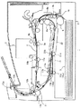
図1は本発明の両面プリント機能を有する中央基準搬送のインクジェット式画像形成装置本体図である。シート材搬送の流れおよび本発明の特徴となるシート材反転装置の説明は以下の通り。 FIG. 1 is a view of the main body of an inkjet image forming apparatus with central reference transport having a double-sided printing function according to the present invention. The flow of the sheet material conveyance and the description of the sheet material reversing device which is a feature of the present invention are as follows.
カセット2に積載収容されているシート材5は、給紙ローラ6により分離され、画像形成装置本体1内を一点鎖線に記すシート材搬送路中に給紙されていく。画像形成装置本体1内に配置されている搬送ローラ対10,12,13,21、および拍車斜送ローラ対15,16,17の構成はすべて、シート材の画像形成面側に位置する側が従動拍車ローラとなり、その対向側は駆動ローラとなっている。そのため乾燥途上の画像形成面が上記ローラを通過する際に生じやすい弊害、すなわちローラ表面にインクが転写されて汚されてしまいシート材表面にその汚れをスタンプ状に次々と転写してしまうことを防ぐ構成となっている。
The
上記分離されたシート材が搬送ローラ対7を通過した後、LFローラ対9によりその先端部が挟持されると印字可能な状態となる。紙面垂直方向への往復運動するキャリッジ3と上記分離されたシート材を搬送するLFローラ対9とがそれぞれ間欠的に運動しつつ、上記キャリッジ3が往復運動している間、具備されるインクジェットヘッド4がインク滴をシート材表面に向けて吐出することにより上記シート材表面に所定の画像形成を達成する。上記シート材先端は画像形成の進捗に応じてフラッパ11、搬送ローラ対12、13を通過後、画像形成装置本体1の機外にむけた方向に搬送されていく。片面プリントの場合はその方向のままに上記シート材は機外に排出される。一方、両面プリントの場合は、搬送ローラ対12,13の搬送区間に画像形成終了したシート材の後端が位置すると、搬送ローラ12,13を回転駆動する不図示のモータが逆転する。
After the separated sheet material passes through the conveying roller pair 7, if the leading end is sandwiched by the LF roller pair 9, printing is possible. Inkjet head provided while the carriage 3 reciprocates while the carriage 3 reciprocating in the vertical direction of the paper and the LF roller pair 9 conveying the separated sheet material move intermittently. 4 achieves predetermined image formation on the surface of the sheet material by ejecting ink droplets toward the surface of the sheet material. The leading edge of the sheet material is conveyed in the direction toward the outside of the image forming apparatus
上記不図示のモータの逆転動作により、摩擦クラッチを介してモータに連結されるフラッパ11は搬送経路を切り換えるよう上方向(図中矢印方向)に回動している間は、後述する装置構成によりモータからの駆動力が所定時間伝達されないので搬送ローラ対12,13はシート材を挟持したままフラッパ11の回動に必要十分な時間のみシート材搬送を停止する。
By the reverse rotation of the motor (not shown), the
引き続きモータを逆転駆動すると、搬送ローラ対12,13には不図示のモータの駆動力が伝達されて、上記シート材の後端を今度は先端として両面搬送路を構成する搬送ガイド14にむけてシート材搬送を行う。
When the motor is continuously driven in the reverse direction, the driving force of the motor (not shown) is transmitted to the pair of conveying rollers 12 and 13, and this time, toward the
この搬送ガイド14を上記シート材が通過する際、シート材はそのシート幅に対応した搬送経路を択一的に搬送されていき、いずれかのシート材斜送手段となる拍車斜送ローラ対15,16,17のひとつを通過する。その結果、各シート幅に応じた設計基準位置にシート材がきちんと位置するようレジストレーション動作が行われる。
When the sheet material passes through the
この一連の搬送動作によって片面プリント済のシート材は表裏が反転されており、搬送ローラ対21,8を通過後、画像形成部であるLFローラ対9にむけて再び給紙されることにより、今度はシート材裏面に画像形成動作がなされ、搬送ローラ対12,13により排出されて両面プリントを達成する。 By this series of conveyance operations, the front and back sides of the sheet material printed on one side are reversed, and after passing through the conveyance roller pairs 21 and 8, the sheet material is fed again toward the LF roller pair 9 which is an image forming unit, This time, an image forming operation is performed on the back surface of the sheet material, and the sheet is discharged by the conveying roller pairs 12 and 13 to achieve double-sided printing.
図2はシート材反転装置断面図である。 FIG. 2 is a cross-sectional view of the sheet material reversing device.
請求項1記載の第1〜3搬送部は記載したシート材搬送区間の通りであり、搬送切換手段とはフラッパ11のことであり、はバネ111によって11bの方向になるよう一方向に引張り力が作用している。搬送切換手段であるフラッパ11の請求項1記載の第1の姿勢とは11aの状態であり、第2の姿勢とは11bの状態である。請求項1記載のローラ対とは搬送ローラ対12のことであり、駆動ローラとは12aのことである。
The first to third conveyance sections according to
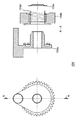
図3は両面搬送経路のシート材反転装置全体図であり、対応する構成品間の駆動系統図は図6である。ここで請求項1記載の駆動ローラ軸上の係合部とは平行ピン108、駆動伝達手段とはギヤ106、摩擦伝達手段とは摩擦クラッチ104、駆動手段とはモータ101である。
FIG. 3 is an overall view of the sheet material reversing device of the double-sided conveyance path, and the drive system diagram between corresponding components is FIG. Here, the engaging portion on the drive roller shaft according to
(摩擦クラッチ104の構成)
図5に摩擦クラッチ104の構成を記載する。
(Configuration of friction clutch 104)
FIG. 5 shows the configuration of the
請求項1記載の摩擦部材とは上記ギヤ104bであり、非摩擦部材とはアーム部材104aのことであり、上述の通りアーム部材104aはフラッパ11と接することで、その姿勢を第1の姿勢に位置させるための部材である。
The friction member according to
摩擦クラッチはアーム部材104a、ギヤ104b、止め輪104c、圧縮バネ104dの4部品から構成される。圧縮バネ104dを包含するギヤ104bが、アーム部材104aの軸部と勘合して止め輪104cにより締結されている。圧縮バネ104dの押圧力をアーム部材104a、ギヤ104bの両部材対向面で受ける構成となっているため(矢印部)、ギア104bに駆動がかかるとその摩擦力によりアーム部材104aと一体となって回転する。しかし、アーム部材104aに上記摩擦トルク以上の負荷がにアーム部材104aに加わると、摩擦面にてすべりが生じて、ギア104bと、アーム部材104aは回転差が生じ互いに差動しあう機械要素として機能する。
The friction clutch is composed of four parts: an
(駆動ローラ12aの構成)
図4に駆動ローラ12aの構成を記載する。
(Configuration of
FIG. 4 shows the configuration of the
請求項1の係合部とは駆動伝達手段であるギヤ106上に形成される////部のことであり、被係合部材とは平行ピン108である。
The engaging portion of
搬送ローラ対12を構成する駆動ローラ12aは、平行ピン108をその軸に通して図示する駆動列のギヤ16と軸勘合している。同様に搬送ローラ対13を構成する駆動ローラ13aも平行ピン108をその軸上に通して図示するプーリ107と軸勘合している。
The
駆動ローラ12aは図示せぬ軸受で支持されており、ギヤ106の上記係合部と駆動ローラ12a上の平行ピン108とが接触しない状態では、駆動力が伝達されない構成となっている。
The driving
本構成はメカタイマーとして駆動系統内で機能する機械要素となる。 This configuration is a mechanical element that functions as a mechanical timer in the drive system.
図3は両面搬送経路のシート材反転装置全体図である。 FIG. 3 is an overall view of the sheet material reversing device in the double-sided conveyance path.
ここでモータ101が所定方向に回転駆動すると各ギヤ、およびプーリにより構成される駆動系全体が回転駆動し、摩擦クラッチ104が図示する矢印CCW方向に回転すると、斜線部/////の部位がフラッパと接触し、上記図2記載の第1の姿勢にフラッパ11を矢印DOWN方向に押し下げ、第1搬送部をシート材搬送可能となる状態にすることができる。
Here, when the
上記図1の解説のごとく表面に画像形成されたシート材の後端がローラ対12を通過した後、モータ101を逆転動作すれば、上記駆動ローラ12aの構成の通り、平行ピン108はギア106と係合しなくなり、ギヤ106の駆動力が駆動ローラ12aに伝達されず、結果として搬送ローラ12,13によるシート材搬送が停止する状態となる。
As described in FIG. 1 above, if the rear end of the sheet material imaged on the surface passes through the roller pair 12 and then the
一方、摩擦クラッチ104は逆転動作しているため、フラッパ11を第1の姿勢に附勢し続けていたアーム部材104がフラッパ11からリリース方向に回転し、フラッパ11はバネ111の作用力によって第2の姿勢に位置した後、搬送ローラ12,13に駆動力が伝達されてシート材を両面搬送パスに導くことが可能となる。
On the other hand, since the
以上の通り、フラッパの切換駆動と関連するローラ対の回転駆動とを共通の駆動源によって動作させる構成でありながら、アクチュエータを必要とせず、且つ駆動源を停止することなくフラッパの切換動作に必要な時間だけ、シート材搬送を停止することが可能なシート材反転装置を提供することによって、装置小型化・コストダウン化が実現可能となる。 As described above, the switching drive of the flapper and the rotational driving of the associated roller pair are operated by a common driving source, but the actuator is not required and the switching operation of the flapper is not required without stopping the driving source. By providing a sheet material reversing apparatus capable of stopping sheet material conveyance for a short time, it is possible to reduce the size and cost of the apparatus.
1 画像形成装置本体
2 カセット
3 キャリッジ
4 インクジェットヘッド
5 シート材
6 給紙ローラ
7 搬送ローラ対
7a 駆動ローラ
7b 従動ローラ
8 搬送ローラ対
8a 駆動ローラ
8b 従動ローラ
9 LF(ラインフィード)ローラ対
9a 駆動ローラ
9b 従動ローラ
10 搬送ローラ対
10a 駆動ローラ
10b 従動拍車ローラ
11a 第1の姿勢のフラッパ
11b 第2の姿勢のフラッパ
12 搬送ローラ対
12a 駆動ローラ
12b 従動拍車ローラ
13 搬送ローラ対
13a 駆動ローラ
13b 従動拍車ローラ
14 搬送ガイド
15 拍車斜送ローラ対
15a 駆動ローラ
15b 従動拍車ローラ
16 拍車斜送ローラ対
16a 駆動ローラ
16b 従動拍車ローラ
17 拍車斜送ローラ対
17a 駆動ローラ
17b 従動拍車ローラ
21 搬送ローラ対
21a 駆動ローラ
21b 従動拍車ローラ
22 搬送ガイド
101 モータ
102a プーリ
102b ギヤ
103 ギヤ
104 摩擦クラッチ
104a アーム部材
104b ギヤ
104c 止め輪
104d 圧縮バネ
105 ギヤ
106 ギヤ
107 プーリ
108 平行ピン
109 ベルト1
110 ベルト2
111 バネ
112 被係合部
P,Pn(n=1,2,…) シート材
1 Image forming device
2 cassette
3 Carriage
4 Inkjet head
5 Sheet material
6 Feed roller
7 Conveyor roller pair
7a Drive roller
7b Followed roller
8 Transport roller pair
8a Drive roller
8b driven roller
9 LF (line feed) roller pair
9a Drive roller
9b Followed roller
10 Transport roller pair
10a Drive roller
10b driven spur roller
11a Flapper in first position
11b Flapper in second position
12 Transport roller pair
12a Drive roller
12b driven spur roller
13 Transport roller pair
13a Drive roller
13b driven spur roller
14 Transport guide
15 spur skew feeding roller pair
15a Drive roller
15b driven spur roller
16-spur inclined roller pair
16a Drive roller
16b driven spur roller
17 Spur-feed roller pair
17a Drive roller
17b driven spur roller
21 Conveyor roller pair
21a Drive roller
21b driven spur roller
22 Transport guide
101 motor
102a pulley
102b gear
103 Gear
104 Friction clutch
104a Arm member
104b gear
104c retaining ring
104d compression spring
105 gear
106 gear
107 pulley
108 parallel pins
109
110 Belt 2
111 Spring
112 engaged part
P, Pn (n = 1,2,…) Sheet material
Claims (1)
上記第1搬送部から上記第2搬送部にシート材を搬送する方向に上記駆動手段が正転し続けて、上記シート材後端が上記搬送経路切換手段を通過した後、第3搬送部へシート材搬送を行う為に上記駆動手段を逆転することにより、上記搬送経路切換手段が第1の姿勢から第2の姿勢への移動中、上記駆動ローラ対が回転停止するに十分な減速比を有する駆動系列により、上記駆動手段から上記駆動伝達手段へ駆動力伝達が行われてシート材を第1搬送部から第3搬送部へ反転搬送することを特徴とするシート材反転装置。 In the transport path having the transport path switching means located in the first posture in the transport section between the first transport section and the second transport section, on the driving roller shaft of the roller pair disposed in the second transport section An engagement portion is formed, and the drive roller and the drive transmission means rotate together as a result of the engagement portion abutting on the drive transmission means that is rotationally fitted around the drive roller shaft. In a friction transmission means that is formed with an engaged portion and presses the friction member and the friction member against each other to transmit a driving force, the friction member is connected to a driving means for rotating the driving transmission means The friction member is connected to the conveying path switching means with respect to the apparatus configuration.
The drive means continues to rotate forward in the direction in which the sheet material is conveyed from the first conveyance section to the second conveyance section, and after the trailing edge of the sheet material passes the conveyance path switching means, to the third conveyance section By reversing the driving means for carrying the sheet material, a reduction ratio sufficient to stop the rotation of the driving roller pair while the conveying path switching means is moving from the first position to the second position is obtained. A sheet material reversing apparatus characterized in that a driving force is transmitted from the driving means to the drive transmitting means by a driving system, and the sheet material is reversed and conveyed from the first conveying unit to the third conveying unit.
Priority Applications (1)
| Application Number | Priority Date | Filing Date | Title |
|---|---|---|---|
| JP2005340609A JP2007145476A (en) | 2005-11-25 | 2005-11-25 | Sheet material reversing device |
Applications Claiming Priority (1)
| Application Number | Priority Date | Filing Date | Title |
|---|---|---|---|
| JP2005340609A JP2007145476A (en) | 2005-11-25 | 2005-11-25 | Sheet material reversing device |
Publications (1)
| Publication Number | Publication Date |
|---|---|
| JP2007145476A true JP2007145476A (en) | 2007-06-14 |
Family
ID=38207354
Family Applications (1)
| Application Number | Title | Priority Date | Filing Date |
|---|---|---|---|
| JP2005340609A Withdrawn JP2007145476A (en) | 2005-11-25 | 2005-11-25 | Sheet material reversing device |
Country Status (1)
| Country | Link |
|---|---|
| JP (1) | JP2007145476A (en) |
Cited By (5)
| Publication number | Priority date | Publication date | Assignee | Title |
|---|---|---|---|---|
| JP2009001403A (en) * | 2007-06-25 | 2009-01-08 | Brother Ind Ltd | Image recorder |
| JP2013075763A (en) * | 2011-09-30 | 2013-04-25 | Brother Industries Ltd | Image recording apparatus |
| JP2016064909A (en) * | 2014-09-25 | 2016-04-28 | ブラザー工業株式会社 | Image recording device |
| JP2019214433A (en) * | 2018-06-11 | 2019-12-19 | セイコーエプソン株式会社 | Medium conveying device and recording device |
| CN114392895A (en) * | 2022-02-24 | 2022-04-26 | 深圳鼎生源电子科技有限公司 | Automatic glue spraying and curing machine |
-
2005
- 2005-11-25 JP JP2005340609A patent/JP2007145476A/en not_active Withdrawn
Cited By (6)
| Publication number | Priority date | Publication date | Assignee | Title |
|---|---|---|---|---|
| JP2009001403A (en) * | 2007-06-25 | 2009-01-08 | Brother Ind Ltd | Image recorder |
| JP2013075763A (en) * | 2011-09-30 | 2013-04-25 | Brother Industries Ltd | Image recording apparatus |
| JP2016064909A (en) * | 2014-09-25 | 2016-04-28 | ブラザー工業株式会社 | Image recording device |
| JP2019214433A (en) * | 2018-06-11 | 2019-12-19 | セイコーエプソン株式会社 | Medium conveying device and recording device |
| JP7155632B2 (en) | 2018-06-11 | 2022-10-19 | セイコーエプソン株式会社 | Medium conveying device and recording device |
| CN114392895A (en) * | 2022-02-24 | 2022-04-26 | 深圳鼎生源电子科技有限公司 | Automatic glue spraying and curing machine |
Similar Documents
| Publication | Publication Date | Title |
|---|---|---|
| JP5056906B2 (en) | Image recording device | |
| JP4820314B2 (en) | Paper feeder | |
| JP5348377B2 (en) | Roll paper transport device and image forming apparatus | |
| JP2007145476A (en) | Sheet material reversing device | |
| JP5888220B2 (en) | Image recording device | |
| JP6460311B2 (en) | Image recording device | |
| JP2017065891A (en) | Conveyor and image recording apparatus | |
| JP5532202B2 (en) | RECORDED MEDIUM CONVEYING DEVICE, RECORDING DEVICE | |
| JP2007264546A (en) | Transfer roller contact/separation driving device and image forming apparatus | |
| JP4920882B2 (en) | Conveying member releasing device and image forming apparatus having the same | |
| JP2005187208A (en) | Sheet feeder, sheet handling device, and image forming device | |
| TWI540055B (en) | Tractor unit, conveyance device, and printer | |
| JP5623809B2 (en) | Conveying device, electronic apparatus including the same, and conveying method | |
| JP2008049677A (en) | Printer device | |
| JP6140552B2 (en) | Paper transport device | |
| JP5927154B2 (en) | RECORDED MEDIUM CONVEYING DEVICE, RECORDING DEVICE | |
| JP5987400B2 (en) | Conveying apparatus and image recording apparatus | |
| JP2011057421A (en) | Device for carrying roll paper and image forming device | |
| JP3501912B2 (en) | Electrophotographic equipment | |
| JP3934037B2 (en) | Card reverse transport mechanism | |
| JP4328759B2 (en) | Sheet-like member conveying device and document double-sided reading device | |
| JP6906982B2 (en) | Printing equipment | |
| JP2011162314A (en) | Recorder | |
| JP3660122B2 (en) | Recording device | |
| JP4029728B2 (en) | Continuous paper printer |
Legal Events
| Date | Code | Title | Description |
|---|---|---|---|
| A300 | Withdrawal of application because of no request for examination |
Free format text: JAPANESE INTERMEDIATE CODE: A300 Effective date: 20090203 |