JP2007137125A - Vehicle side mirror - Google Patents
Vehicle side mirror Download PDFInfo
- Publication number
- JP2007137125A JP2007137125A JP2005330336A JP2005330336A JP2007137125A JP 2007137125 A JP2007137125 A JP 2007137125A JP 2005330336 A JP2005330336 A JP 2005330336A JP 2005330336 A JP2005330336 A JP 2005330336A JP 2007137125 A JP2007137125 A JP 2007137125A
- Authority
- JP
- Japan
- Prior art keywords
- housing
- lamp unit
- mirror
- vehicle
- side mirror
- Prior art date
- Legal status (The legal status is an assumption and is not a legal conclusion. Google has not performed a legal analysis and makes no representation as to the accuracy of the status listed.)
- Pending
Links
Images
Landscapes
- Rear-View Mirror Devices That Are Mounted On The Exterior Of The Vehicle (AREA)
- Lighting Device Outwards From Vehicle And Optical Signal (AREA)
Abstract
Description
本発明は、後方を確認するためのミラーを備えた車両用サイドミラーに関するものである。 The present invention relates to a vehicle side mirror provided with a mirror for confirming the rear.
従来、後方を確認するためのミラーを備えた車両用サイドミラーとして、車両の進路方向を示す方向指示ランプが設けられたものが知られている。 2. Description of the Related Art Conventionally, a vehicle side mirror provided with a mirror for confirming the rear is provided with a direction indicator lamp that indicates a course direction of the vehicle.
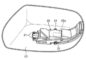
図7は、このような方向指示ランプを備えた車両用サイドミラーの従来の例を示す斜視図である。図7に示すように、方向指示ランプが設けられた車両用サイドミラーは、一般に、図略のミラーを支持するハウジング23と、方向指示ランプ25aを保持するランプユニット25とを備えており、このランプユニット25がハウジング23に対してねじ21で固定されるように構成されている。
FIG. 7 is a perspective view showing a conventional example of a vehicle side mirror provided with such a direction indicating lamp. As shown in FIG. 7, a vehicle side mirror provided with a direction indicator lamp generally includes a
例えば、特許文献1には、ミラーハウジングの前面から後ろ側へ回り込んだ車幅方向外側端にかけて横長の切欠き部を形成し、この切欠き部にいわゆるサイドターンランプと呼ばれる方向指示ランプを保持するランプユニットが後ろ側から取り付られた車両用ドアミラーの技術が開示されている。
しかしながら、図7に示した車両用サイドミラーや上述の公報に記載された車両用サイドミラーなどの従来技術では、ランプユニットとハウジングとをねじで固定する必要があったので、ハウジングに対するランプユニットの取り付けに時間がかかり、車両用サイドミラーの製造に係るコストの低減に限界があるという問題があった。 However, in the prior art such as the vehicle side mirror shown in FIG. 7 and the vehicle side mirror described in the above-mentioned publication, it is necessary to fix the lamp unit and the housing with screws. There is a problem that it takes time to mount and there is a limit to the cost reduction for manufacturing the vehicle side mirror.
また、上述の車両用サイドミラーの従来技術では、ハウジングの周縁部を切り欠いているので、ハウジングの周縁部を切り欠いてデザイン性を向上させた構造を採用しようとすると、ハウジング周縁部において強度が低下するという問題があった。 Further, in the above-described conventional vehicle side mirror technology, since the peripheral portion of the housing is cut out, if an attempt is made to adopt a structure in which the peripheral portion of the housing is cut out to improve the design, the strength at the peripheral portion of the housing is increased. There was a problem that decreased.
本発明は上記不具合に鑑みてなされたものであり、ランプユニットとハウジングとをねじで固定する必要を無くすることにより、ハウジングに対するランプユニットの取り付けを省力化して車両用サイドミラーの製造に係るコストを大幅に低減することができる車両用サイドミラーを提供することを課題としている。 The present invention has been made in view of the above-described problems, and eliminates the need to fix the lamp unit and the housing with screws, thereby saving labor for mounting the lamp unit to the housing and reducing the cost associated with the production of the vehicle side mirror. An object of the present invention is to provide a vehicle side mirror capable of significantly reducing the above.
また、デザイン性を向上させることなどを目的としてハウジングの周縁部を切り欠いた構造を採用しても、ハウジング周縁部の強度を維持することができる車両用サイドミラーを提供することを課題としている。 It is another object of the present invention to provide a vehicle side mirror that can maintain the strength of the peripheral edge of the housing even when a structure in which the peripheral edge of the housing is cut out is employed for the purpose of improving design. .
上記課題を解決するための本発明は、車両において後方を確認するためのミラーと、このミラーを支持するハウジングと、車両の進路方向を示す方向指示ランプとを有する車両用サイドミラーであって、上記方向指示ランプを保持するとともにハウジングに支持されるランプユニットを備え、上記ランプユニットとハウジングのどちらか一方に設けられた係止爪が、他方に設けられた係合部に係止されて、ランプユニットがハウジングに固定されるものであることを特徴とする車両用サイドミラーである。 The present invention for solving the above-mentioned problems is a vehicle side mirror having a mirror for confirming the rear in the vehicle, a housing that supports the mirror, and a direction indicator lamp that indicates a course direction of the vehicle, A lamp unit that holds the direction indicating lamp and is supported by the housing is provided, and a locking claw provided on one of the lamp unit and the housing is locked to an engaging portion provided on the other, A side mirror for a vehicle, wherein the lamp unit is fixed to a housing.
本発明によれば、係止爪が、係合部に係止されて、ランプユニットがハウジングに固定されるので、ランプユニットとハウジングとをねじで固定する必要がなくなる結果、ハウジングに対するランプユニットの取り付けが省力化され、車両用サイドミラーの製造に係るコストを大幅に低減することができるようになる。 According to the present invention, since the locking claw is locked to the engaging portion and the lamp unit is fixed to the housing, it is not necessary to fix the lamp unit and the housing with screws. Installation is labor-saving, and the cost for manufacturing the vehicle side mirror can be greatly reduced.
ここで、上記ハウジングは、ランプユニットの端部に設けられた挿入部を挿脱可能に受け入れて、このランプユニットの挿入部をハウジングに位置決めする位置決めホルダー部を備えていることが好ましい。 Here, it is preferable that the housing includes a positioning holder portion that removably receives an insertion portion provided at an end portion of the lamp unit and positions the insertion portion of the lamp unit in the housing.
この好ましい態様によれば、ハウジングに設けられた位置決めホルダー部が、ランプユニットの端部に設けられた挿入部を挿脱可能に受け入れて、位置決めするので、ハウジングに対してランプユニットを精度良く取り付けることができるようになる。また、係止爪と係合部との係止による固定だけの場合と比較して、より堅固に確実にハウジングに対してランプユニットを取り付けることができるようになる。 According to this preferable aspect, the positioning holder portion provided in the housing receives and positions the insertion portion provided in the end portion of the lamp unit so as to be detachable, and thus the lamp unit is attached to the housing with high accuracy. Will be able to. In addition, the lamp unit can be attached to the housing more firmly and securely than in the case of only fixing by locking the locking claw and the engaging portion.
次に、上記ハウジングの上記位置決めホルダー部は、ハウジングの周縁部においてハウジングの内側に突出するアーチ状に形成されたものであることが好ましい。 Next, it is preferable that the positioning holder portion of the housing is formed in an arch shape projecting inward of the housing at a peripheral edge portion of the housing.
この好ましい態様によれば、位置決めホルダー部が、ハウジングの内側に突出するアーチ状に形成されてハウジングの周縁部に設けられているので、位置決めホルダー部が設けられたハウジングの周縁部の強度を増加させることができる。その結果、アーチ状に形成された位置決めホルダー部を残してハウジングの周縁部を切り欠いても、このアーチ状に形成された位置決めホルダー部がハウジング周縁部の強度を維持することができるようになる結果、ハウジングの周縁部を切り欠いてデザイン性を向上させた構造を採用することができるようになる。 According to this preferable aspect, since the positioning holder part is formed in the arch shape protruding inside the housing and provided at the peripheral part of the housing, the strength of the peripheral part of the housing provided with the positioning holder part is increased. Can be made. As a result, even if the peripheral portion of the housing is cut away while leaving the positioning holder portion formed in an arch shape, the positioning holder portion formed in the arch shape can maintain the strength of the peripheral portion of the housing. As a result, it is possible to employ a structure in which the peripheral portion of the housing is cut out to improve the design.
また、上記ハウジングの上記位置決めホルダー部は、ランプユニットの端部に設けられ、ランプユニットから配線が出入りするコネクタ部を受け入れてハウジングに位置決めするものであることが好ましい。 Further, the positioning holder portion of the housing is preferably provided at an end portion of the lamp unit and receives a connector portion through which wiring enters and exits from the lamp unit to position the housing on the housing.
この好ましい態様によれば、位置決めホルダー部が、配線が出入りするコネクタ部を受け入れて位置決めするので、車両の動きに伴い振動を起こしやすい配線部に連なるコネクタ部をより堅固に確実にハウジングに対してランプユニットを取り付けることができるようになる。 According to this preferable aspect, the positioning holder portion receives and positions the connector portion through which the wiring enters and exits, so that the connector portion connected to the wiring portion that is likely to vibrate with the movement of the vehicle is more firmly and securely attached to the housing. The lamp unit can be attached.
また、上記ハウジングの上記位置決めホルダー部は、ハウジングを塗装台の所定の位置に位置決めして塗装する際に、塗装台の所定の位置に設けられたハウジング固定治具に係合可能なものであることが好ましい。 Further, the positioning holder portion of the housing is engageable with a housing fixing jig provided at a predetermined position of the coating table when the housing is positioned and applied at a predetermined position of the coating table. It is preferable.
この好ましい態様によれば、ハウジングを塗装する際に、塗装台の所定の位置に設けられたハウジング固定治具に位置決めホルダー部を係合させてハウジングを位置決めすることができるので、塗装工程用のリブをハウジングに別途取り付ける必要がなく、車両用サイドミラーの製造に係るコストを低減することができるようになる。 According to this preferable aspect, when painting the housing, the positioning holder portion can be engaged with the housing fixing jig provided at a predetermined position of the painting stand so that the housing can be positioned. There is no need to separately attach the rib to the housing, and the cost for manufacturing the vehicle side mirror can be reduced.
以上説明したように、本発明によれば、ランプユニットとハウジングとをねじで固定する必要がなくなるので、ハウジングに対するランプユニットの取り付けが省力化され、車両用サイドミラーの製造に係るコストを大幅に低減することができるという顕著な効果を奏する。 As described above, according to the present invention, since it is not necessary to fix the lamp unit and the housing with screws, the mounting of the lamp unit to the housing is saved, and the cost for manufacturing the vehicle side mirror is greatly reduced. There is a remarkable effect that it can be reduced.
また、ハウジングの内側に突出するアーチ状に形成された位置決めホルダー部をハウジングの周縁部に設けた場合には、ハウジングの周縁部の強度を増加させることができるので、デザイン性を向上させた構造を採用することなどを目的としてハウジングの周縁部を切り欠いても、ハウジング周縁部の強度を維持することができるようになる。 In addition, when the positioning holder part formed in the shape of an arch that protrudes to the inside of the housing is provided on the peripheral part of the housing, the strength of the peripheral part of the housing can be increased, so that the design is improved. Even if the peripheral portion of the housing is cut out for the purpose of adopting the above, the strength of the peripheral portion of the housing can be maintained.
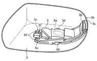
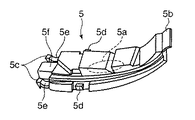
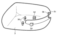
以下、添付図面を参照しながら本発明の好ましい実施の一形態について詳述する。図1は、本発明の実施形態に係る車両用サイドミラー10の構成を示す説明図であり、図2は、本発明の実施の形態に係る車両用サイドミラー10のハウジング3とランプユニット5との連結を示す斜視図である。また、図3は、ランプユニット5の構成を示す斜視図を、図4は、ハウジング3の構成を示す斜視図をそれぞれ示している。
Hereinafter, a preferred embodiment of the present invention will be described in detail with reference to the accompanying drawings. FIG. 1 is an explanatory diagram showing a configuration of a
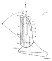
図1を参照して、図示の本発明の実施形態に係る車両用サイドミラー10は、車両において後方を確認するためのミラー1と、ミラー1を保持するミラーホルダ2と、ミラーホルダ2を保持するとともに車体側に支持されるハウジング3と、ハウジング3を支持するためのベース4とを備えている。そして、ハウジング3の内部には、車両の進路方向を示す方向指示ランプ5aと、この方向指示ランプ5aを保持するとともにハウジング3に支持されるランプユニット5と、ミラーホルダ2の角度を調節するミラー角度調節機構6と、ミラー角度調節機構6を支持するフレーム7と、フレーム7とともにハウジング3をベース4に対して回動させて車体に沿う格納姿勢にするバイザー格納機構8とが組み込まれている。
Referring to FIG. 1, a
上記ミラー1は、ガラス材料の裏面に高反射率の金属を真空蒸着、その他の方法でコーティングしてミラー1を形成したものであり、本実施形態では、広角に後方を確認することができるようにするために、凸面構造の鏡面1aが採用されている。
The mirror 1 is formed by applying a highly reflective metal on the back surface of a glass material by vacuum deposition or other methods to form the mirror 1. In this embodiment, the rear can be confirmed at a wide angle. Therefore, the
上記ミラーホルダ2は、ミラー1を保持するために設けられたものであり、外形がミラー1とほぼ同じ形に形成されてミラー1の裏面を覆うとともに、ミラーホルダ2の周縁部に設けたミラー係止部2aにミラー1の周縁を係止して、ミラー1と一体化されている。
The
上記ハウジング3は、ミラー1を支持するものであり、ミラー1の角度を調節するミラー角度調節機構6や、バイザー格納機構8、その他を内部に収納するための容器状の合成樹脂製成形品で構成されている。このハウジング3は、フレーム7を介してバイザー格納機構8に連結され、ベース4に対して揺動変位可能に構成されている。本実施形態では、ハウジング3の後部には、ミラーホルダ2の縁部を覆うようにして保護するミラーカバー3aが、ハウジング3と別々に一体成型され、ハウジング3に嵌合連結されている。
The
上記ハウジング3は、図2と図4とに示すように、ランプユニット5の端部に設けられた挿入部5bを挿脱可能に受け入れて、このランプユニット5の挿入部5bをハウジング3に位置決めする位置決めホルダー部3bを備えている。
As shown in FIGS. 2 and 4, the
そして、このハウジング3の位置決めホルダー部3bは、ハウジング3の周縁部3cにおいてハウジング3の内側に突出するアーチ状に形成されている。本実施形態では、車両用サイドミラー10のデザイン性を向上させるために、アーチ状に形成された位置決めホルダー部3bを残してハウジング3の周縁部3cが切り欠かれた形状に構成されており、このハウジング3には、ハウジング3と別々に一体成型されたミラーカバー3a(図1)が、嵌合連結される構造になっている。
And the
また、このハウジング3の位置決めホルダー部3bは、ハウジング3を塗装する際に、塗装台の所定の位置に設けられた図略のハウジング固定治具に係合されるようになっており、これによりハウジング3が塗装台の所定の位置に位置決めされるようになっている。
Further, the
上記ベース4は、バイザー格納機構8に連結され、ハウジング3を支持するための構造体である図略のベースインナと、ベースカバー4aとを備えている。このベースカバー4aは、ベースインナを覆うようにして、ベースの外皮を構成するものであり、合成樹脂で一体成形して形成されている。
The
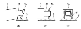
上記ランプユニット5は、高輝度ハロゲンランプなどから構成される方向指示ランプ5aを内部に保持しており、図2と図3とに示すように、このランプユニット5に設けられた係止爪5c、5dが、ハウジング3に設けられた係合部3dに係止されて、ランプユニット5がワンタッチでハウジング3に固定されるように構成されている。
The
ここで、ランプユニット5のコネクタ部5f近傍に設けられた一対の係止爪5cには、アーム部5eが設けられており、このアーム部5eが、弾性的に撓んでハウジング3に設けられた係合部3dに対する導入をスムースなものにしている。
Here, a pair of locking
また、ランプユニット5の側部に設けられた一対の係止爪5dの場合は、ランプユニット5の側部と、ハウジング3に設けられた門型の係合部3dとが相互に僅かに撓んで係合部3dに対してスムースに導入されるように構成されている。
In the case of the pair of locking
上記ミラー角度調節機構6(図1)は、ハウジング3内でミラーホルダ2の設置角度を左右方向及び上下方向に微調整可能に支持するためのものである。ミラーホルダ2を手動で回動させる機構とすることも可能であるが、本実施形態では、ミラー角度調節機構6に設けられる図略の電動モータでその傾斜角を調整して最適角度に調整できるように構成されており、ミラーホルダ2の裏面中心の回転支軸となる図略のピボットセンタを中心としてミラーホルダ2を回動させる角度調節アクチュエータ6bを有している。
The mirror angle adjusting mechanism 6 (FIG. 1) is for supporting the installation angle of the
上記フレーム7(図1)は、ミラー角度調節機構6を支持するために設けられたものである。このフレーム7は、図略のビス等により、ハウジング3にも連結されており、ミラー角度調節機構6とハウジング3とを一体化するとともに、これらをバイザー格納機構8に連結している。
The frame 7 (FIG. 1) is provided to support the mirror angle adjustment mechanism 6. The
上記バイザー格納機構8は、ミラーホルダ2、ミラー角度調節機構6およびフレーム7を収納するハウジング3をベース4に対して図1の矢印rで示す範囲内で揺動変位させることにより、ハウジング3を車体に沿うように格納するための機構であり、詳細は省略するが、手動機構または電動機構が採用されている。
The
次に図1を参照して、本発明の実施の形態に係る車両用サイドミラー10の作用について説明する。
Next, the operation of the
図1に示すように、本発明の実施の形態に係る車両用サイドミラー10においては、ハウジング3の位置決めホルダー部3bが、ランプユニット5の端部に設けられた挿入部5bを挿脱可能に受け入れて、このランプユニット5の挿入部5bをハウジング3に位置決めする。
As shown in FIG. 1, in the
また、ランプユニット5のコネクタ部5f近傍に設けられた一対の係止爪5c(図3)と、ランプユニット5の側部に設けられた一対の係止爪5d(図3)とが、ハウジング3に設けられた門型の係合部3dに係止されて、ランプユニット5がワンタッチでハウジング3に固定される。
In addition, a pair of locking
このように、ランプユニット5の挿入部5bがハウジング3の位置決めホルダー部3bに位置決めされ、ランプユニット5の係止爪5c、5dがハウジング3の係合部3dに係止されることにより、ランプユニット5がハウジング3に精度良く、堅固に支持される。
In this way, the
また、ハウジング3が塗装される際には、位置決めホルダー部3bが、塗装台の所定の位置に設けられた図略のハウジング固定治具に係合されて、ハウジング3が塗装台の所定の位置に位置決めされる。
Further, when the
以上説明したように、本発明の実施の形態に係る車両用サイドミラー10によれば、係止爪5c、5dが、係合部3dに係止されて、ランプユニット5がハウジング3に固定されるので、ランプユニット5とハウジング3とをねじで固定する必要がなくなる結果、ハウジング3に対するランプユニット5の取り付けが省力化され、車両用サイドミラー10の製造に係るコストを大幅に低減することができるようになる。
As described above, according to the
次に、ハウジング3に設けられたアーチ状の位置決めホルダー部3bが、ランプユニット5の端部に設けられた挿入部5bを挿脱可能に受け入れて、位置決めするので、ハウジング3に対してランプユニット5を精度良く取り付けることができるようになる。また、係止爪5c、5dと係合部3dとの係止による固定だけの場合と比較して、より堅固に確実にハウジング3に対してランプユニット5を取り付けることができるようになる。
Next, the arch-shaped
また、位置決めホルダー部3bが、ハウジング3の内側に突出するアーチ状に形成されてハウジング3の周縁部3cに設けられているので、位置決めホルダー部3bが設けられたハウジング3の周縁部3cの強度を増加させることができる。その結果、アーチ状に形成された位置決めホルダー部3bを残してハウジング3の周縁部3cを切り欠いても、このアーチ状に形成された位置決めホルダー部3bがハウジング3周縁部3cの強度を維持することができるようになる結果、ハウジング3の周縁部3cを切り欠いてデザイン性を向上させた構造を採用することができるようになる。
Further, since the
さらに、ハウジング3を塗装する際に、塗装台の所定の位置に設けられた図略のハウジング固定治具に位置決めホルダー部3bを係合させてハウジング3を位置決めすることができるので、塗装工程用のリブをハウジング3に別途取り付ける必要がなく、車両用サイドミラー10の製造に係るコストを低減することができるようになる。
Furthermore, when painting the
上述した実施の形態は本発明の好ましい具体例を例示したものに過ぎず、本発明は上述した実施の形態に限定されない。 The above-described embodiment is merely a preferred specific example of the present invention, and the present invention is not limited to the above-described embodiment.
例えば、ハウジング3の位置決めホルダー部3bは、図5に示すように、ランプユニット5の端部に設けられ、ランプユニット5から配線が出入りするコネクタ部5f側に設けられ、このコネクタ部5fを受け入れてハウジング3に位置決めするものであってもよい。図5は、ハウジング3の位置決めホルダー部3bが、ランプユニット5のコネクタ部5fを位置決めする作用を示す説明図であり、(a)は、コネクタ部5fの導入過程の側面図を、(b)は、コネクタ部5fの導入後の側面図を、(c)は、コネクタ部5fの導入後のもう一方の側面図を、それぞれ示している。
For example, as shown in FIG. 5, the
このような構成の場合は、位置決めホルダー部3bが、配線が出入りするコネクタ部5fを受け入れて位置決めするので、車両の動きに伴い振動を起こしやすい配線部に連なるコネクタ部5fをより堅固に確実にハウジング3に対してランプユニット5を取り付けることができるようになる。
In such a configuration, since the
次に、係合部3dは必ずしも門型に限定されない。係止爪5c、5dを係合可能な形状であれば、係合部3dは、フック形状や爪形状など、その他の形状を有する構造であってもよい。
Next, the engaging
また、必ずしも、係止爪5c、5dが弾力的に撓んで係合部3dに係止されるような構成に限定されるものではなく、係合部3dが弾力的に撓んで係止爪を係止するような構成も採用可能である。
In addition, the configuration is not necessarily limited to the configuration in which the locking
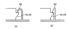
例えば、図6は、弾力的に撓むその他の形状の係合部3dの例を示す説明図であり、(a)は、弾力的に撓むフック形状の係合部3dの構成を示す側面図を、(b)は、弾力的に撓む爪形状の係合部3dの構成を示す側面図を、それぞれ示している。
For example, FIG. 6 is an explanatory diagram showing an example of another shape of the engaging
さらに、本実施形態に係る車両用サイドミラー10は、必ずしも、ランプユニット5側に係止爪が設けられ、ハウジング3側に係合部が設けられるような構成に限定されるものではなく、逆に、ハウジング3側に係止爪が設けられ、ランプユニット5側に係合部が設けられるような構成であっても採用可能である。
Furthermore, the
その他、本発明の特許請求の範囲内で種々の設計変更が可能であることはいうまでもない。 In addition, it goes without saying that various design changes are possible within the scope of the claims of the present invention.
1 ミラー
3 ハウジング
3b 位置決めホルダー部
3c 周縁部
3d 係合部
5 ランプユニット
5a 方向指示ランプ
5b 挿入部
5c、5d 係止爪
5f コネクタ部
10 車両用サイドミラー
DESCRIPTION OF SYMBOLS 1
Claims (5)
上記方向指示ランプを保持するとともにハウジングに支持されるランプユニットを備え、
上記ランプユニットとハウジングのどちらか一方に設けられた係止爪が、他方に設けられた係合部に係止されて、ランプユニットがハウジングに固定されるものであることを特徴とする車両用サイドミラー。 A vehicle side mirror having a mirror for confirming a rear side in a vehicle, a housing that supports the mirror, and a direction indicator lamp that indicates a course direction of the vehicle,
A lamp unit that holds the direction indicator lamp and is supported by the housing;
The vehicle is characterized in that a locking claw provided on one of the lamp unit and the housing is locked to an engaging portion provided on the other, and the lamp unit is fixed to the housing. Side mirror.
Priority Applications (1)
| Application Number | Priority Date | Filing Date | Title |
|---|---|---|---|
| JP2005330336A JP2007137125A (en) | 2005-11-15 | 2005-11-15 | Vehicle side mirror |
Applications Claiming Priority (1)
| Application Number | Priority Date | Filing Date | Title |
|---|---|---|---|
| JP2005330336A JP2007137125A (en) | 2005-11-15 | 2005-11-15 | Vehicle side mirror |
Publications (1)
| Publication Number | Publication Date |
|---|---|
| JP2007137125A true JP2007137125A (en) | 2007-06-07 |
Family
ID=38200531
Family Applications (1)
| Application Number | Title | Priority Date | Filing Date |
|---|---|---|---|
| JP2005330336A Pending JP2007137125A (en) | 2005-11-15 | 2005-11-15 | Vehicle side mirror |
Country Status (1)
| Country | Link |
|---|---|
| JP (1) | JP2007137125A (en) |
Cited By (7)
| Publication number | Priority date | Publication date | Assignee | Title |
|---|---|---|---|---|
| JP2011051435A (en) * | 2009-08-31 | 2011-03-17 | Murakami Corp | Positioning structure for turn lamp assembly of outer mirror with turn lamp |
| JP2012089371A (en) * | 2010-10-20 | 2012-05-10 | Mitsuba Corp | Door mirror |
| JP2012116225A (en) * | 2010-11-29 | 2012-06-21 | Tokai Rika Co Ltd | Mirror device for vehicle |
| JP2014104830A (en) * | 2012-11-27 | 2014-06-09 | Sakae Riken Kogyo Co Ltd | Mirror device |
| JP2015071416A (en) * | 2014-11-26 | 2015-04-16 | 株式会社東海理化電機製作所 | Vehicular mirror device |
| JP2020185821A (en) * | 2019-05-10 | 2020-11-19 | 株式会社ホンダロック | Vehicular door mirror device |
| CN112553993A (en) * | 2019-09-26 | 2021-03-26 | 梅特勒-托莱多有限责任公司 | Tensile reinforcement structure for concrete slab |
-
2005
- 2005-11-15 JP JP2005330336A patent/JP2007137125A/en active Pending
Cited By (15)
| Publication number | Priority date | Publication date | Assignee | Title |
|---|---|---|---|---|
| DE102010027685B4 (en) | 2009-08-31 | 2023-06-07 | Murakami Corp. | Positioning structure of an indicator lamp assembly in an outside mirror with an indicator lamp |
| CN102001308A (en) * | 2009-08-31 | 2011-04-06 | 株式会社村上开明堂 | Positioning structure of turn lamp assembly in outer mirror with turn lamp |
| US8480273B2 (en) | 2009-08-31 | 2013-07-09 | Murakami Corporation | Positioning structure of turn lamp assembly in outer mirror with turn lamp |
| JP2011051435A (en) * | 2009-08-31 | 2011-03-17 | Murakami Corp | Positioning structure for turn lamp assembly of outer mirror with turn lamp |
| JP2012089371A (en) * | 2010-10-20 | 2012-05-10 | Mitsuba Corp | Door mirror |
| JP2012116225A (en) * | 2010-11-29 | 2012-06-21 | Tokai Rika Co Ltd | Mirror device for vehicle |
| US8568006B2 (en) | 2010-11-29 | 2013-10-29 | Kabushiki Kaisha Tokai-Rika-Denki-Seisakusho | Mirror device for vehicle |
| JP2014104830A (en) * | 2012-11-27 | 2014-06-09 | Sakae Riken Kogyo Co Ltd | Mirror device |
| JP2015071416A (en) * | 2014-11-26 | 2015-04-16 | 株式会社東海理化電機製作所 | Vehicular mirror device |
| JP2020185821A (en) * | 2019-05-10 | 2020-11-19 | 株式会社ホンダロック | Vehicular door mirror device |
| WO2020230687A1 (en) * | 2019-05-10 | 2020-11-19 | 株式会社ホンダロック | Vehicular door mirror device |
| JP7086029B2 (en) | 2019-05-10 | 2022-06-17 | 株式会社ホンダロック | Vehicle door mirror device |
| US11691569B2 (en) | 2019-05-10 | 2023-07-04 | Kabushiki Kaisha Honda Lock | Vehicular door mirror device |
| CN112553993A (en) * | 2019-09-26 | 2021-03-26 | 梅特勒-托莱多有限责任公司 | Tensile reinforcement structure for concrete slab |
| CN112553993B (en) * | 2019-09-26 | 2024-04-02 | 梅特勒-托莱多有限责任公司 | Tensile reinforcement structure for concrete slab |
Similar Documents
| Publication | Publication Date | Title |
|---|---|---|
| US7798552B2 (en) | Sun visor holder | |
| US8562061B2 (en) | Sun visor for vehicles | |
| EP3173289B1 (en) | Camera bracket with metal wire spring | |
| JP2007137125A (en) | Vehicle side mirror | |
| KR101740268B1 (en) | Over head consol lamp plate for vehicle | |
| CN101861256B (en) | Mounting structure for outside mirror unit | |
| JP2010089641A (en) | Vehicle wiper | |
| JP3714837B2 (en) | Method for assembling vehicle door mirror device | |
| JPH09270201A (en) | Vehicle lighting | |
| US7975974B2 (en) | Adjustable lamp | |
| US20050217054A1 (en) | Wiper blade connecting structure | |
| WO2020085181A1 (en) | Vehicle sun visor | |
| JP2001082758A (en) | Indoor unit of air conditioner | |
| JP2013001191A (en) | Panel mounting structure of door mirror for vehicle | |
| JP2006069276A (en) | Rear camera mounting structure | |
| KR100683219B1 (en) | Automotive Headlight Module | |
| JP2015044433A (en) | Sun visor for vehicle | |
| JP2002029255A (en) | Sun visor for vehicle | |
| JP3990597B2 (en) | Mirror device for vehicle | |
| JP2010272332A (en) | Inner lens mounting structure for vehicle lamp | |
| JP2008195087A (en) | Door mirror | |
| JP2007308115A (en) | Vehicular auxiliary sun visor | |
| JP2007176310A (en) | Temporary holding structure of audio device for vehicle | |
| JP4276443B2 (en) | Car lamp mounting structure | |
| JPS631380Y2 (en) |