JP2007136397A - Paste coating apparatus and display panel manufacturing apparatus using the same - Google Patents
Paste coating apparatus and display panel manufacturing apparatus using the same Download PDFInfo
- Publication number
- JP2007136397A JP2007136397A JP2005336326A JP2005336326A JP2007136397A JP 2007136397 A JP2007136397 A JP 2007136397A JP 2005336326 A JP2005336326 A JP 2005336326A JP 2005336326 A JP2005336326 A JP 2005336326A JP 2007136397 A JP2007136397 A JP 2007136397A
- Authority
- JP
- Japan
- Prior art keywords
- screw
- cylinder
- paste
- opening
- sealing agent
- Prior art date
- Legal status (The legal status is an assumption and is not a legal conclusion. Google has not performed a legal analysis and makes no representation as to the accuracy of the status listed.)
- Withdrawn
Links
Images

Landscapes
- Liquid Crystal (AREA)
- Coating Apparatus (AREA)
Abstract
【課題】 ペーストを吐出する吐出装置のスクリューの回転角度による吐出量のばらつきを少なくすることができるペースト塗布装置及びこれを用いた表示パネルの製造装置を提供すること。
【解決手段】 ノズル36を有するシリンダ40内に、螺旋状の凸条Tを形成した棒状のスクリュー41を設け、スクリュー41を回転させることによりシリンダ40内のペーストSを軸方向に送り出してノズル36から吐出させるペースト塗布装置10において、スクリュー41は螺旋状の凸条T1、T2を複数条有するもの。
【選択図】 図2PROBLEM TO BE SOLVED: To provide a paste coating apparatus and a display panel manufacturing apparatus using the same, which can reduce variation in the discharge amount due to the rotation angle of a screw of a discharge apparatus for discharging paste.
A rod-shaped screw 41 having a spiral ridge T formed therein is provided in a cylinder 40 having a nozzle 36. By rotating the screw 41, paste S in the cylinder 40 is sent out in the axial direction and the nozzle 36 is rotated. In the paste coating apparatus 10 to be discharged from the screw, the screw 41 has a plurality of spiral ridges T1 and T2.
[Selection] Figure 2
Description
本発明は、ペーストを塗布するペースト塗布装置及びこれを用いた表示パネルの製造装置に関し、特に、液晶表示装置の製造過程に用いて好適なペースト塗布装置及び表示パネルの製造装置に関する。 The present invention relates to a paste coating apparatus for applying a paste and a display panel manufacturing apparatus using the same, and more particularly to a paste coating apparatus and a display panel manufacturing apparatus suitable for use in a manufacturing process of a liquid crystal display device.
ガラス基板上にペーストとしてのシール剤でパターンを描画する技術としては、ノズルからシール剤を吐出させつつ、基板とノズルのいずれか一方を他方に対して平行な水平面内で移動させることによりパターンを描画する方法が知られている。上記方法において、従来のペースト塗布装置では、シリンジ内に予め設定された圧力の気体圧力をかけることにより、ノズルからシール剤を吐出させて基板上に塗布する。このとき、基板を上面に保持するステージをノズルに対して平行に移動させるようにしている。 As a technique for drawing a pattern with a sealant as a paste on a glass substrate, the pattern is formed by moving one of the substrate and nozzle in a horizontal plane parallel to the other while discharging the sealant from the nozzle. A method of drawing is known. In the above method, in the conventional paste application apparatus, a gas pressure of a preset pressure is applied to the syringe to discharge the sealant from the nozzle and apply it onto the substrate. At this time, the stage holding the substrate on the upper surface is moved in parallel with the nozzle.
しかしながら、気体圧力によりシール剤をノズルから吐出させる方式では、基板上面とノズルとの間のギャップが変動すると、ノズルからのシール剤の吐出抵抗が変動してシール剤の吐出量が変化する。また、周囲温度の変化によりシール剤の粘度が変化すると、シール剤がノズルを通過するときの抵抗が変わり、ノズルからの吐出量が変化する。また、シリンジ内のシール剤の残量が減少することによってもノズルからのシール剤の吐出量が減少する。その結果、均一な塗布量でシール剤を基板上に塗布することができなくなるという問題がある。 However, in the method in which the sealing agent is discharged from the nozzle by the gas pressure, when the gap between the upper surface of the substrate and the nozzle is changed, the discharge resistance of the sealing agent from the nozzle is changed and the discharge amount of the sealing agent is changed. Further, when the viscosity of the sealing agent changes due to a change in the ambient temperature, the resistance when the sealing agent passes through the nozzle changes, and the discharge amount from the nozzle changes. Moreover, the discharge amount of the sealing agent from the nozzle also decreases as the remaining amount of the sealing agent in the syringe decreases. As a result, there is a problem that the sealing agent cannot be applied onto the substrate with a uniform application amount.
そこで、このような問題を解決するものとして、図7に示すように、シリンダ140内に外周に1条の螺旋状の凸条Tを有する棒状のスクリュー141を設け、スクリュー141をモータ144により回転させることにより、シリンダ140内のシール剤Sを送り出してノズル136から吐出させるようにした吐出装置135がある。この場合、スクリュー141のリードをL、ピッチをPとすると、L=Pである。この吐出装置135によれば、ギャップの変動やシール剤の粘度の変化に関係なく、モータ144が回転した量に相当するシール剤Sをノズル136から吐出させることができるので、均一な塗布量でシール剤Sを基板上に塗布することができる。
In order to solve such a problem, as shown in FIG. 7, a rod-
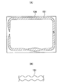
しかしながら、シリンダ140内にスクリュー141を設けた吐出装置135には、図8に示すように、シリンダ140がスクリュー141に対して偏心していると、スクリュー141の回転角度によって、螺旋状の凸条Tの間の螺旋状の溝Gの軸方向の先端における開口部Aの外周とシリンダ140内周との間の距離(隙間、以下同じ)Hが異なる。図8(A)に示す如く、開口部Aの外周とシリンダ140の内周との間の距離Hが小さいときは、シール剤Sが開口部を通過するときの抵抗が大きく、吐出量が少なくなる。また、図8(B)に示す如く、開口部Aの外周とシリンダ140の内周との間の距離Hが大きいときは、シール剤Sが開口部Aを通過するときの抵抗が小さく、吐出量が多くなる。そのため、スクリュー141の回転角度によりシール剤Sの吐出量が異なり、図9(A)に示すように、基板126上にシール剤Sが塗布されて形成されたパターン151の塗布量がばらついたり、断線したりするという不具合が発生する。また、図9(B)に示すように、パターン151における塗布量の多い部分と少ない部分が連続する場合もある。液晶表示パネルの製造工程におけるシール剤Sの塗布において、上記の不具合が発生した場合、2枚の基板を貼り合わせて液晶表示パネルを製造する際に、描画パターンが断線した部分や塗布量の少ない部分から液晶が漏れたりパネル内に空気が入ったりして、パネル不良の原因になる。
However, in the
本発明の課題は、ペーストを吐出する吐出装置のスクリューの回転角度による吐出量のばらつきを少なくして塗布量を良好に得ることができるペースト塗布装置及びこれを用いた表示パネルの製造装置を提供することにある。 SUMMARY OF THE INVENTION An object of the present invention is to provide a paste coating apparatus and a display panel manufacturing apparatus using the paste coating apparatus that can obtain a good coating amount by reducing variations in the ejection amount due to the rotation angle of the screw of the ejection device that ejects the paste. There is to do.
請求項1の発明は、ノズルを有するシリンダ内に、螺旋状の凸条又は凹条を形成した棒状のスクリューを設け、スクリューを回転させることによりシリンダ内のペーストを軸方向に送り出してノズルから吐出させるペースト塗布装置において、スクリューは螺旋状の凸条又は凹条を複数条有するものである。 According to the first aspect of the present invention, a rod-like screw having a spiral ridge or a groove is provided in a cylinder having a nozzle, and the paste in the cylinder is sent in the axial direction by rotating the screw to be discharged from the nozzle. In the paste applying apparatus, the screw has a plurality of spiral ridges or ridges.
請求項2の発明は、請求項1の発明において更に、螺旋状の凸条の間に形成される螺旋状の溝又は螺旋状の凹条の軸方向の先端における開口部が、スクリューの外周において等間隔の配置となるようにしたものである。 According to a second aspect of the present invention, in the first aspect of the present invention, the opening at the axial tip of the spiral groove or the spiral recess formed between the spiral ridges is formed on the outer periphery of the screw. It is arranged so as to be equally spaced.
請求項3の発明は、2枚の基板のうち少なくとも一方の基板にペーストを塗布し、ペーストを介して一方の基板と他方の基板を貼り合わせる表示パネルの製造装置において、請求項1又は2に記載のペースト塗布装置を備えるものである。 According to a third aspect of the present invention, there is provided a display panel manufacturing apparatus in which a paste is applied to at least one of two substrates, and the one substrate and the other substrate are bonded together via the paste. The paste applying apparatus is provided.
本発明によれば、ペーストを吐出する吐出装置のスクリューの回転角度による吐出量のばらつきを少なくして塗布量を良好に得ることができる。 ADVANTAGE OF THE INVENTION According to this invention, the dispersion | variation in the discharge amount by the rotation angle of the screw of the discharge apparatus which discharges paste can be decreased, and a coating amount can be obtained favorably.
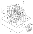
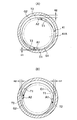
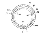
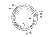
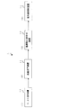
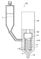
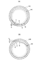
図1はペースト塗布装置を示す斜視図、図2は図1のペースト塗布装置における吐出装置の模式断面図、図3は2条の凸条部を有するスクリューの開口部の外周とシリンダの内周との距離(隙間)を説明するための模式図で、(A)は開口部とシリンダとの距離(隙間)が上下方向で大と小の場合、(B)は開口部とシリンダとの距離(隙間)が左右方向で中と中の場合の模式図、図4は3条の凸条部を有するスクリューの開口部の外周とシリンダの内周との距離(隙間)を説明するための模式図、図5は2条の凸条部を異なるピッチで有するスクリューの開口部の外周とシリンダの内周との距離(隙間)を説明するための模式図、図6は液晶表示パネルの製造工程を示すブロック図、図7は背景技術のペースト塗布装置における吐出装置の模式断面図、図8は1条の凸条部を有するスクリューの開口部の外周とシリンダの内周との距離(隙間)を説明するための模式図で、(A)は開口部とシリンダとの距離(隙間)が小の場合、(B)は開口部とシリンダとの距離(隙間)が大の場合の模式図、図9(A)、(B)はそれぞれ背景技術の吐出装置における塗布パターンを示す模式図である。 1 is a perspective view showing a paste application device, FIG. 2 is a schematic sectional view of a discharge device in the paste application device of FIG. 1, and FIG. 3 is an outer periphery of a screw opening having two ridges and an inner periphery of a cylinder. (A) is the distance between the opening and the cylinder (gap) is large and small in the vertical direction, and (B) is the distance between the opening and the cylinder. FIG. 4 is a schematic diagram for explaining the distance (gap) between the outer periphery of the opening of the screw having the three ridges and the inner periphery of the cylinder. FIG. 5, FIG. 5 is a schematic diagram for explaining the distance (gap) between the outer periphery of the opening of the screw having the two ridges at different pitches and the inner periphery of the cylinder, and FIG. 6 is a manufacturing process of the liquid crystal display panel FIG. 7 is a block diagram showing a discharge device in a paste coating apparatus of the background art. FIG. 8 is a schematic cross-sectional view, FIG. 8 is a schematic diagram for explaining the distance (gap) between the outer periphery of the opening of the screw having one ridge and the inner periphery of the cylinder, and FIG. When the distance (gap) is small, (B) is a schematic diagram when the distance (gap) between the opening and the cylinder is large, and FIGS. 9 (A) and 9 (B) are coatings in the discharge device of the background art, respectively. It is a schematic diagram which shows a pattern.
以下、図面を参照しながらこの発明の実施例を説明する。
液晶表示パネル製造装置1は、図6に示す如く、以下の装置からなり、液晶表示パネルは、概略、以下の工程を経て製造される。
Embodiments of the present invention will be described below with reference to the drawings.
As shown in FIG. 6, the liquid crystal display
工程(1)でペースト塗布装置10にて、2つの矩形のガラス基板のうち下基板に形成された表示領域を囲む周辺部に、ペーストとしてのシール剤を所定の厚み(例えば、30μm)で枠状に塗布した後、工程(2)で液晶滴下装置11にて、下基板のシール剤の内側の表示領域に液晶を滴下する。尚、シール剤を上基板に塗布して、対向する下基板の表示領域に液晶を滴下しても良い。次に、工程(3)で基板貼り合わせ装置12にて、下基板の上に上基板を真空チャンバ中で位置合わせをした後、上下の基板を上下方向に押圧して貼り合わせる。工程(4)で紫外線照射装置13にて、シール剤に紫外線を照射して硬化させ、2つの基板とシール剤の内側に液晶を封入した液晶表示パネルを製造する。
In step (1), the
図1に示すペースト塗布装置10は、上記の工程(1)の上基板又は下基板の周辺部にペーストとしてのシール剤を枠状に塗布するために使用するものである。
A
図1中、X軸とY軸は互いに直交しそれぞれ水平方向に延び、Z軸はX軸とY軸に対して垂直方向に延びる。図1はペースト塗布装置10の概略的構成を示す斜視図であって、ペースト塗布装置10は直方体状のベース20を備える。ベース20の上面に、図1に示すように、Yテーブル22がY軸方向(図1中、ペースト塗布装置10の前後方向)に沿って移動可能に設けられ、Yテーブル22は不図示のボールねじとナット及びボールねじを回動するサーボモータ23からなる駆動手段によって駆動される。Yテーブル22の上面にθ回転機構24を介してステージ25が設けられる。ステージ25はθ回転機構24によって、図1に示すように、Z軸(図1中、ペースト塗布装置10の上下方向)回りに水平面内で回転可能となっている。ステージ25の上面には、液晶表示パネルの製造に用いられるガラス製の矩形の基板26が載置され、不図示の真空吸着等の手段によって吸着保持される。
In FIG. 1, the X axis and the Y axis are orthogonal to each other and extend in the horizontal direction, and the Z axis extends in a direction perpendicular to the X axis and the Y axis. FIG. 1 is a perspective view showing a schematic configuration of a
ベース20の上面には、Yテーブル22を跨ぐ状態で門型の支持体30が設けられる。この支持体30の水平な梁部の前面にY軸方向に直交するX軸方向(図1中、塗布装置10の左右方向)に沿ってガイドレール31が固定される。ガイドレール31上に2つのXテーブル32がX軸方向にそれぞれ移動可能に設けられ、2つのXテーブル32は不図示のリニアモータからなる駆動手段によって駆動される。リニアモータはガイドレール31上に設けられたマグネットとXテーブル32に設けられたコイルからなる。
A gate-
各Xテーブル32上にZテーブル33がZ軸方向(上下方向)に移動可能に設けられ、Zテーブル33はボールねじとナット及びボールねじを回動するサーボモータ34からなる駆動手段によって駆動される。
A Z table 33 is provided on each X table 32 so as to be movable in the Z-axis direction (vertical direction). The Z table 33 is driven by a driving means including a ball screw, a nut, and a
また、各Zテーブル33上に、吐出装置35がそれぞれ設けられる。吐出装置35については、後に詳細に説明するが、概略図2に示す如く、先端部にノズル36を有するシリンダ40内に2条の螺旋状の凸条T1、T2を等ピッチで形成した棒状のスクリュー41を有し、スクリュー41をサーボモータ44により回転させることにより、シリンダ40内のシール剤Sを軸方向に送り出してノズル36から吐出させる。
In addition, a
Zテーブル33上には、レーザ変位計45からなる距離検出器がシリンダ40と一体的に取り付け固定され、レーザ変位計45は基板26上面までの距離を測定する。
On the Z table 33, a distance detector comprising a
また、各Zテーブル33上には、ステージ25上に基板26を位置決めするためのCCDカメラ46からなる撮像装置が設けられる。
In addition, on each Z table 33, an imaging device including a
上記塗布装置10のベース20の一側には制御装置50が設けられる。制御装置50はYテーブル22を駆動するサーボモータ23、Xテーブル32を駆動する不図示のリニアモータ、Zテーブル33を駆動するサーボモータ34をそれぞれ制御する。
A
また、制御装置50は、吐出装置35のスクリュー41を回転駆動するサーボモータ44を制御する。
制御装置50にはモニタ用のディスプレイ52と入力用のキーボード53が接続される。
Further, the
A
次に、上記構成のペースト塗布装置10によって基板26上にシール剤Sを塗布する動作について説明する。
Next, the operation of applying the sealing agent S on the
まず、ステージ25の上面に、不図示のロボット等によって基板26が供給載置されると、基板26に付された不図示のアライメントマークがCCDカメラ46によって撮像され、撮像信号が制御装置50に入力される。制御装置50は、撮像された画像から画像認識により予め設定された位置との間の位置ずれを検出し、そのずれが零となるようにXテーブル32、Yテーブル22、θ回転機構24を制御する。
First, when the
ペースト塗布装置10の制御装置50は、Xテーブル32のリニアモータとYテーブル22のサーボモータ23を駆動してXテーブル32とYテーブル22を水平方向に移動させ、Zテーブル33のサーボモータ34を駆動してZテーブル33を上下方向に移動させる。
The
制御装置50は、2つの吐出装置35のサーボモータ44を駆動してスクリュー41を回転させてノズル36からシール剤Sを吐出させて、X軸方向に並んだ2つのパターン51を同時並行的に塗布描画させる。
The
レーザ変位計45は基板26上面までの距離を測定し、制御装置50は、レーザ変位計45の測定値に基づきノズル36の先端と基板26上面との間隔(以下、ギャップと言う)が常時一定となるようにサーボモータ34を駆動してZテーブル33を移動制御(以下、ギャップ制御と言う)し、均一な幅及び厚さのパターン51を基板26上に塗布描画する。
The
以上のようにして、ペースト塗布装置10は4つのパターン51を基板26上に枠状に塗布描画する。
As described above, the
次に、前述した吐出装置35について、詳細に説明する。
吐出装置35は、前述したように図2に示す如く、先端部にノズル36を有するシリンダ40とシリンダ40の内周に回転自在に設けられた棒状のスクリュー41を備える。スクリュー41は円柱状の軸部41Aの外周に断面四角形の2条の螺旋状の凸条T1、T2を等ピッチPで有し、ピッチPは、背景技術の図7における1条の凸条Tを有するスクリュー141と同一のピッチPからなる。リードLはL=2Pとなる。2条の螺旋状の凸条T1、T2の間に2条の螺旋状の溝G1、G2が形成され、螺旋状の溝G1、G2の軸方向の先端における開口部A1、A2(A1の180度反対側)が、スクリュー41の外周において等間隔の配置となるように設けられる。スクリュー41の螺旋状の凸条T1、T2の外周とシリンダ40の内周との間には微小隙間が形成され、2条の螺旋状の溝G1、G2とシリンダ40の内周との間にそれぞれ螺旋状の液室Rがそれぞれ区画される。
Next, the
As described above, the
尚、スクリュー41は2以上の複数条の螺旋状の凸条Tを有するものであっても良く、また、複数の螺旋状の凸条Tを異なるピッチPで有するものであっても良い。
The
吐出装置35は、シリンダ40の上端の基端部に取り付けられた前述のサーボモータ44を備え、サーボモータ44の回転軸44Aに連結部材54を介してスクリュー41が連結され、スクリュー41はサーボモータ44の回転軸44Aを支持する不図示の軸受けによって支持される。
The
吐出装置35は、更に、シリンダ40と並列に設けられた貯溜容器55を備える。貯溜容器55内にはシール剤Sが貯溜され、シール剤Sの上部に圧力気体室55Aが設けられ、圧力気体室55Aはホース56を介して不図示の気体圧力源に連結される。また、スクリュー41の上端部の螺旋状の凸条T1、T2の外周に対向してシリンダ40の側壁の上部に連通孔60が形成され、この連通孔60にパイプ57を介して貯留容器55の底部が連結される。
The
上記構成からなる吐出装置35のシール剤Sの吐出動作について、以下に説明する。
ペースト塗布装置10の制御装置50は、吐出装置35のサーボモータ44を駆動してスクリュー41を回転させ、螺旋状の溝G1、G2とシリンダ40の内周との間に区画される液室R内のシール剤Sを、螺旋状の溝G1、G2に沿って軸方向に押し出して溝G1、G2の軸方向の先端における2つの開口部A1、A2から吐出させ、更に、シリンダ40の先端のノズル36からシール剤Sを吐出させる。吐出された分のシール剤Sがシリンダ40の貯溜容器55からシリンダ40の連通孔60を介してシリンダ40内に補給され、補給されたシール剤Sはスクリュー41の基端部外周の螺旋状の溝G1、G2の各開口部から吸入される。
The discharge operation of the sealing agent S of the
The
制御装置50は、吐出装置35のスクリュー41を回転駆動させるサーボモータ44を制御して、ノズル36からのシール剤Sの吐出、停止を制御する。
The
尚、スクリュー41の回転が開始されるタイミングよりも予め設定された時間早いタイミングで、気体圧力源から貯留容器55内の圧力気体室55Aへ圧力気体の供給が開始され、また、スクリュー41の回転を停止させるタイミングで圧力気体室55Aへの圧力気体の供給が停止される。
The supply of the pressure gas from the gas pressure source to the
また、シリンダ40内の液室Rをシール剤Sで満たすために、吐出装置35の予備吐出動作が行なわれる。即ち、圧力気体室55A内に圧力気体を供給し、この状態でスクリュー41を回転させる。液室R内がシール剤Sで満たされ、シール剤Sがノズル36から吐出されるまでスクリュー41の回転を継続させる。このとき、シール剤Sがノズル36から吐出された後も設定時間スクリュー41を回転させ続けた方が、液室R内に空気を残留させることなくシール剤Sを液室R内に充満させることができるので好ましい。
Further, in order to fill the liquid chamber R in the
また、ノズル36からのシール剤Sの吐出を停止させるとき、スクリュー41を逆転させることにより、シール剤Sの吐出停止時等におけるノズル36の先端からのシール剤Sの垂れを防止することができる。
Further, when the discharge of the sealing agent S from the
ところで、背景技術のところで図7を参照して説明したように、スクリュー141の軸心とシリンダ140の軸心が偏心していると、スクリュー141の回転角度によって、螺旋状の溝Gの軸方向の先端における開口部Aの外周とシリンダ140内周との間の距離が一定でなくなる。その結果、シール剤Sが開口部Aを通過するときの抵抗が大きくなったり小さくなったりしてスクリュー141の回転角度によりシール剤Sの吐出量が異なり、パターン151の箇所により塗布量がばらついたり、断線したりするという不具合が発生する。
By the way, as described with reference to FIG. 7 in the background art, when the shaft center of the
本実施例の吐出装置35は、スクリュー41の軸心とシリンダ40の軸心が偏心している場合、以下の如く動作する。
The
スクリュー41は2条の螺旋状の凸条T1、T2を等ピッチで有するので、スクリュー41がシリンダ40に対して偏心している場合においてスクリュー41の軸方向先端の外周における2つの溝G1、G2の開口部A1、A2の配置は、図3(A)に示すように、(1)一方の溝G1の開口部A1とシリンダ40の内周との距離(隙間)H1が小で他方の溝G2の開口部A2とシリンダ40内周との距離(隙間)H2が大の場合と、図3(B)に示すように、(2)一方の溝G1と他方の溝G2の各開口部A1、A2とシリンダ40の内周との距離H1、H2が中と中の場合と、(3)上記(1)と(2)の中間の場合がある。図3(A)の場合に、シリンダ40の内周との距離H1が小の位置にある開口部A1の外周での吐出抵抗は大きいのでシール剤Sの吐出量は小であり、また、シリンダ40内周との距離H2が大の位置にある開口部A2の外周での吐出抵抗は小さいのでシール剤Sの吐出量は大である。上記(1)、(2)、(3)いずれの場合もスクリュー41からのシール剤Sの吐出量が平均化される。その結果、スクリューの回転角度に関係なく、一定量のペーストを吐出して単位長さ当りの塗布量を一定にすることができる。
Since the
尚、スクリュー41は2以上の複数条の螺旋状の凸条Tを等間隔で有するものであっても良く、その場合、複数の開口部Aはスクリュー41の先端部の外周に等間隔の配置となり、シール剤Sの吐出量が平均化される。図4に3つの凸条T1、T2、T3を等ピッチで有するスクリュー41を示す。
The
また、スクリュー41は複数条の螺旋状の凸条Tを異なるピッチPで有するものであっても良い。図5は、2つの凸条T1、T2を異なるピッチPで有するスクリュー41の場合の例で、2つの開口部A1、A2がスクリュー41の外周に円周方向に90度分散した配置となっている。この場合、図5に示すように、一方の開口部A1がシリンダ40の内周との距離が最小となる位置にあるときには、他方の開口部A2におけるシリンダ40の内周との距離は一方の開口部A1よりも大きい。また、一方の開口部A1がシリンダ40の内周との距離が最大となる位置にあるときには、他方の開口部A2におけるシリンダ40の内周との距離は一方の開口部A1よりも小さい。従って、一方の開口部A1からのシール剤Sの供給量が少ないとき、他方の開口部A2からはそれよりも多い量でシール剤Sが供給され、一方の開口部A1からのシール剤Sの供給量が多いとき、他方の開口部A2からそれよりも少ない量でシール剤Sが供給される。このように、一方の開口部A1におけるシール剤Sの供給量のバラツキは、他方の開口部A2によって緩和される。よって、背景技術のように1条の凸条Tを有するスクリュー141を用いた場合に比べ、ノズル36からのシール剤Sの吐出量を平均化することができる。
The
次に、開口部A1、A2の外周とシリンダ40の内周との間における吐出抵抗は、スクリュー41を支持する作用をなす。図3(A)に示す如く、シリンダ40の内周との距離(隙間)H1が小で吐出抵抗が大きい開口部A1の外周では、距離(隙間)H2が大で吐出抵抗が小さい開口部A2の外周より、スクリュー41をその中心方向へ押す作用が大きい。これは、開口部A1側では吐出抵抗が大きい分、シール剤Sの反力が強く作用するためである。そして、この開口部A1側のシール剤Sの反力は、図3(B)に示す状態に近づくに従い徐々に減少し、図3(B)に示す状態において開口部A2側と等しくなる。一方、開口部A2側では、シール剤Sの反力は、図3(A)に示す状態から図3(B)に示す状態に近づくに従い徐々に増加する。この結果、スクリュー41の先端部は、シール剤Sの反力により、偏心を矯正する方向へ常に押圧されることとなる。従って、本実施例のように、スクリュー41を上端部側で片持ち支持する構造においては、スクリュー41の先端部側の偏心がシール剤Sの反力によって矯正されることとなる。そのため、2つの開口部A1、A2によってシール剤Sの吐出量が平均化されるうえ、スクリュー41の偏心が矯正されるので、シール剤Sをより均一な吐出量で吐出させることができる。
Next, the discharge resistance between the outer periphery of the openings A1 and A2 and the inner periphery of the
次に、2条の凸条T1、T2を有するスクリュー41が、背景技術の図7における1条の凸条Tを有するスクリュー141と同一のピッチPからなるので、スクリュー41が一回転するとシール剤Sは1リード分、即ち、2ピッチ分のシール剤Sを吐出する。従って、背景技術における吐出装置と同一の吐出量を得るのに必要な回転数は1/2となる。
Next, since the
尚、この場合、2条の凸条T1、T2を有するスクリュー41のピッチは必ずしも1条の凸条Tを有するスクリュー141と同一のピッチPである必要はなく、同等以上のピッチを等ピッチで有するスクリュー41であれば良い。
In this case, the pitch of the
本実施例によれば、以下の作用効果を奏する。
(a)ペースト塗布装置10のスクリュー41は螺旋状の凸条Tを複数条備えるので、螺旋状の凸条Tの間の螺旋状の溝Gの軸方向の先端における開口部Aが、スクリュー41の外周において円周方向に分散して配置される。その結果、スクリュー41がシリンダ40に対して偏心している場合、螺旋状の溝Gの開口部Aの外周とシリンダ40内周との距離が小さい部分と大きい部分が生じる。シリンダ40内周との距離H1が小さい開口部A1の外周における吐出抵抗は大となりシール剤Sの吐出量が小となり、また、シリンダ40内周との距離H2が大きい開口部A2の外周における吐出抵抗は小となりシール剤Sの吐出量が大となる。従って、シリンダ40内周との距離H1が小さい開口部A1における小の吐出量と距離H2が大きい開口部A2における大の吐出量とで、スクリュー41から吐出されるシール剤Sの吐出量が開口部A1、A2の配置の角度に応じて平均化される。この場合、開口部A1、A2の配置が等間隔に近づくにつれて吐出量はより平均化される。従って、スクリュー41の回転角度による吐出量のばらつきを、1条の螺旋状の凸条Tの場合に比べて、少なくすることができる。
According to the present embodiment, the following operational effects can be obtained.
(a) Since the
(b)ペースト塗布装置10のスクリュー41は螺旋状の凸条Tを複数条備え、かつ、螺旋状の凸条T1、T2との間に形成される螺旋状の溝G1、G2の軸方向の先端における開口部A1、A2が、スクリュー41の外周部において等間隔の配置となるように設けられる。その結果、開口部A1の外周とシリンダ40の内周との距離H1が小さい開口部A1における小の吐出量と距離H2が大きい開口部A2における大の吐出量とで、スクリュー41から吐出されるシール剤Sの吐出量が平均化され、偏心していない場合の吐出量と同一又は同一に近くなる。従って、スクリュー41の回転角度に関係なく、一定量のシール剤Sを吐出して単位長さ当りの塗布量を一定にすることができる。
(b) The
(c)螺旋状の凸条T1、T2との間に形成される螺旋状の溝G1、G2の軸方向の先端における開口部A1、A2が、スクリュー41の外周部において等間隔の配置となるように設けられる。その結果、開口部A1、A2の外周とシリンダ40の内周におけるシール剤Sの吐出抵抗により、スクリュー41にその偏心を矯正する力が作用することとなる。即ち、溝G1の開口部A1とシリンダ40の内周との距離L1が小さい側ではシール剤Sの反力が大きく、距離L2が大きい側ではシール剤Sの反力が小さい。そのため、スクリュー41の偏心がシール剤Sの反力によって矯正され、シール剤Sをより均一な吐出量で吐出させることができる。
(c) The openings A1 and A2 at the axial ends of the spiral grooves G1 and G2 formed between the spiral ridges T1 and T2 are arranged at equal intervals on the outer periphery of the
(d)ペースト塗布装置10のスクリュー41は複数条の螺旋状の凸条Tを等ピッチPで備える。複数条の凸条Tを等ピッチPで有するスクリュー41の条数をnとすると、リードLはL=nPとなる。また、1条の凸条Tを有するスクリュー141と同一のピッチPを等ピッチで有するn条の凸条Tを有するスクリュー41が1条の凸条Tを有するスクリュー141と同一の吐出量を得るために必要なモータの回転数は1/nとなる。その結果、スクリュー41を回転駆動するモータの回転数は1/nで済むので、スクリュー41とシール剤S又はシール剤S同士の摩擦、又は、モータの発熱がシール剤Sに伝わること等によって、シール剤Sが発熱して硬化したり劣化したりすることを抑えることができ、高価なシール剤Sを廃却することによる損失の発生を防止できる。
(d) The
また、シール剤Sの劣化を抑えることができることにより、製造される液晶表示パネルの品質を向上させることができる。 Moreover, since the deterioration of the sealing agent S can be suppressed, the quality of the manufactured liquid crystal display panel can be improved.
(e)2枚の基板のうち少なくとも一方の基板26に、基板26に形成された表示領域を囲むようにシール剤Sを塗布し、シール剤Sを介して一方の基板26と他方の基板を貼り合わせる液晶表示パネルの製造装置1は、上記のペースト塗布装置10を備える。その結果、ペースト塗布装置10にて均一な厚み及び塗布幅のパターン51が基板26上に塗布されるので、シール剤Sで囲まれた液晶表示パネルの内部の液晶等が漏れたり、液晶表示パネル内に空気が入ったりすることを防止できるので、液晶表示パネルの不良の発生を防止できる。
(e) The sealing agent S is applied to at least one of the two
以上、本発明の実施例を図面により詳述したが、本発明の具体的な構成はこの実施例に限られるものではなく、本発明の要旨を逸脱しない範囲の設計の変更等があっても本発明に含まれる。 The embodiment of the present invention has been described in detail with reference to the drawings. However, the specific configuration of the present invention is not limited to this embodiment, and even if there is a design change or the like without departing from the gist of the present invention. It is included in the present invention.
例えば、軸部の外周に凸条を有する例で説明したが、凸条に代えて、円柱状の軸部の外周に螺旋状の凹条を有するものとしても良い。しかしながら、螺旋状の凸条を有するものとするか凹条を有するものとするかは、螺旋状の溝の底部を軸部とみて凸条を有するとするか、螺旋状の凸条の頂部を軸部とみて凹条を有するとするかの表現上の相違に過ぎないので、凹条を有する場合も含むことは言うまでもない。 For example, although the example which has a protruding item | line on the outer periphery of an axial part demonstrated instead of a protruding item | line, it is good also as what has a helical concave item on the outer periphery of a cylindrical shaft part. However, whether to have a spiral ridge or a recess is to have a ridge with the bottom of the spiral groove as a shaft, or the top of the spiral ridge. Since it is only a difference in expression as to whether it has a groove when viewed as a shaft portion, it goes without saying that it also includes a case having a groove.
また、ギャップ制御を行なう例で説明したが、ギャップ制御を省いても良い。この場合、ギャップ制御を全く行なわないようにしても良いし、ノズルを塗布開始点に位置付けるときのみギャップ制御を行ない、パターンの描画中はギャップ制御を省くようにしても良い。 Further, although an example of performing the gap control has been described, the gap control may be omitted. In this case, the gap control may not be performed at all, or the gap control may be performed only when the nozzle is positioned at the application start point, and the gap control may be omitted during pattern drawing.
また、ペースト塗布装置は、基板上にシール剤を塗布するものに限らない。例えば、プリント基板等の回路基板に導電性回路パターンを形成するものであっても良い。 Further, the paste application device is not limited to one that applies a sealing agent on a substrate. For example, a conductive circuit pattern may be formed on a circuit board such as a printed board.
また、線状のパターンを塗布する例で説明したが、点状のパターンを塗布するようにしても良い。 Further, although an example in which a linear pattern is applied has been described, a dot pattern may be applied.
また、液晶表示パネル製造装置の例で説明したが、表示パネルの製造装置は液晶以外の物質、例えば、有機又は無機EL物質であっても良い。 Moreover, although demonstrated in the example of the liquid crystal display panel manufacturing apparatus, the display panel manufacturing apparatus may be materials other than a liquid crystal, for example, organic or inorganic EL material.
1 液晶表示パネル製造装置
10 ペースト塗布装置
26 基板
36 ノズル
40 シリンダ
41 スクリュー
A、A1、A2 開口部
G、G1、G2 溝
S シール剤(ペースト)
T、T1、T2 凸条
DESCRIPTION OF
T, T1, T2
Claims (3)
前記スクリューは前記螺旋状の凸条又は凹条を複数条有することを特徴とするペースト塗布装置。 In a paste application device that provides a rod-like screw having a spiral ridge or groove in a cylinder having a nozzle, and sends the paste in the cylinder in the axial direction by rotating the screw to be discharged from the nozzle.
The screw has a plurality of the spiral ridges or ridges, and the paste coating apparatus is characterized in that:
請求項1又は2に記載のペースト塗布装置を備えることを特徴とする表示パネルの製造装置。 In a display panel manufacturing apparatus in which a paste is applied to at least one of two substrates, and one substrate is bonded to the other through the paste.
An apparatus for manufacturing a display panel, comprising the paste coating apparatus according to claim 1.
Priority Applications (4)
| Application Number | Priority Date | Filing Date | Title |
|---|---|---|---|
| JP2005336326A JP2007136397A (en) | 2005-11-21 | 2005-11-21 | Paste coating apparatus and display panel manufacturing apparatus using the same |
| KR1020087011233A KR100965476B1 (en) | 2005-11-21 | 2006-11-16 | Paste application device and paste application method |
| PCT/JP2006/322856 WO2007058258A1 (en) | 2005-11-21 | 2006-11-16 | Paste applying apparatus, method for manufacturing display panel using same and paste applying method |
| TW095142778A TW200727018A (en) | 2005-11-21 | 2006-11-20 | Spread-coating apparatus and which using it for the display panel and its fabricating method |
Applications Claiming Priority (1)
| Application Number | Priority Date | Filing Date | Title |
|---|---|---|---|
| JP2005336326A JP2007136397A (en) | 2005-11-21 | 2005-11-21 | Paste coating apparatus and display panel manufacturing apparatus using the same |
Publications (1)
| Publication Number | Publication Date |
|---|---|
| JP2007136397A true JP2007136397A (en) | 2007-06-07 |
Family
ID=38199888
Family Applications (1)
| Application Number | Title | Priority Date | Filing Date |
|---|---|---|---|
| JP2005336326A Withdrawn JP2007136397A (en) | 2005-11-21 | 2005-11-21 | Paste coating apparatus and display panel manufacturing apparatus using the same |
Country Status (1)
| Country | Link |
|---|---|
| JP (1) | JP2007136397A (en) |
Cited By (4)
| Publication number | Priority date | Publication date | Assignee | Title |
|---|---|---|---|---|
| KR101270994B1 (en) | 2011-05-31 | 2013-06-04 | 주식회사 케이씨텍 | Photoresist supplying pump for coater apparatus |
| KR101279347B1 (en) * | 2011-10-19 | 2013-07-04 | 주식회사 에스에프이 | Apparatus for supplying adhesive |
| KR101364674B1 (en) * | 2011-03-18 | 2014-02-19 | 가부시키가이샤 히타치세이사쿠쇼 | Paste application head, paste application apparatus and paste application method |
| CN114464777A (en) * | 2022-02-09 | 2022-05-10 | 博众精工科技股份有限公司 | Rubberizing device |
-
2005
- 2005-11-21 JP JP2005336326A patent/JP2007136397A/en not_active Withdrawn
Cited By (5)
| Publication number | Priority date | Publication date | Assignee | Title |
|---|---|---|---|---|
| KR101364674B1 (en) * | 2011-03-18 | 2014-02-19 | 가부시키가이샤 히타치세이사쿠쇼 | Paste application head, paste application apparatus and paste application method |
| KR101270994B1 (en) | 2011-05-31 | 2013-06-04 | 주식회사 케이씨텍 | Photoresist supplying pump for coater apparatus |
| KR101279347B1 (en) * | 2011-10-19 | 2013-07-04 | 주식회사 에스에프이 | Apparatus for supplying adhesive |
| CN114464777A (en) * | 2022-02-09 | 2022-05-10 | 博众精工科技股份有限公司 | Rubberizing device |
| CN114464777B (en) * | 2022-02-09 | 2023-11-03 | 博众精工科技股份有限公司 | Rubberizing device |
Similar Documents
| Publication | Publication Date | Title |
|---|---|---|
| CN102553845B (en) | Nozzle cleaning device and there is the sealant coater of nozzle cleaning device | |
| JP7098169B2 (en) | Liquid material coating equipment and coating method | |
| KR101885010B1 (en) | Method and apparatus for automatically adjusting dispensing units of a dispenser | |
| TWI797090B (en) | Working device and working method | |
| JP6925143B2 (en) | Droplet ejection device, droplet ejection method, program and computer storage medium | |
| CN104203579A (en) | Print head for stencil printer | |
| KR101157348B1 (en) | Droplet applying apparatus, droplet applying method, apparatus for manufacturing liquid crystal display panel and method for manufacturing liquid crystal display panel | |
| TWI291901B (en) | Apparatus for applying paste and method of applying paste | |
| CN1635949A (en) | Apparatus for Microcoating Various Fluid Materials | |
| US20060193969A1 (en) | Method and apparatus for streaming a viscous material on a substrate | |
| WO2014069498A1 (en) | Work device having a position correction function, and work method | |
| JP7713468B2 (en) | Tilt Rotating Dispenser with Harmonic Gear System | |
| TW201330735A (en) | Method for depositing materials on a substrate | |
| US20170333936A1 (en) | Segmented or selected-area coating | |
| JP3916898B2 (en) | Manufacturing method of liquid crystal panel, manufacturing apparatus and manufacturing system thereof | |
| KR100965476B1 (en) | Paste application device and paste application method | |
| JP7465648B2 (en) | Adhesive application device, adhesive application method, and rotor manufacturing method | |
| TWI441689B (en) | Coating device and its coating position correction method | |
| JP4940806B2 (en) | Paste application machine and paste application method | |
| JP7194152B2 (en) | Applicator, applicator, and applicator method | |
| KR20070041391A (en) | Paste Applicator | |
| TWI686242B (en) | Applying apparatus | |
| KR20030093952A (en) | Film forming apparatus, filling method of liquid-shape body thereof, device manufacturing method and device manufacturing apparatus, and device | |
| JP2010221186A (en) | Coating apparatus and coating body manufacturing method | |
| JP5355060B2 (en) | Inkjet coating apparatus and method of manufacturing coated body |
Legal Events
| Date | Code | Title | Description |
|---|---|---|---|
| A300 | Withdrawal of application because of no request for examination |
Free format text: JAPANESE INTERMEDIATE CODE: A300 Effective date: 20090203 |