JP2007123749A - Wiring board fixing structure - Google Patents
Wiring board fixing structure Download PDFInfo
- Publication number
- JP2007123749A JP2007123749A JP2005317195A JP2005317195A JP2007123749A JP 2007123749 A JP2007123749 A JP 2007123749A JP 2005317195 A JP2005317195 A JP 2005317195A JP 2005317195 A JP2005317195 A JP 2005317195A JP 2007123749 A JP2007123749 A JP 2007123749A
- Authority
- JP
- Japan
- Prior art keywords
- wiring board
- case
- locking claw
- claw member
- fixing structure
- Prior art date
- Legal status (The legal status is an assumption and is not a legal conclusion. Google has not performed a legal analysis and makes no representation as to the accuracy of the status listed.)
- Granted
Links
- 210000000078 claw Anatomy 0.000 claims abstract description 83
- 230000001105 regulatory effect Effects 0.000 claims abstract description 7
- 230000002265 prevention Effects 0.000 description 10
- 229920003002 synthetic resin Polymers 0.000 description 5
- 239000000057 synthetic resin Substances 0.000 description 5
- 230000008878 coupling Effects 0.000 description 3
- 238000010168 coupling process Methods 0.000 description 3
- 238000005859 coupling reaction Methods 0.000 description 3
- 238000005452 bending Methods 0.000 description 2
- 230000037431 insertion Effects 0.000 description 2
- 238000003780 insertion Methods 0.000 description 2
- 230000015572 biosynthetic process Effects 0.000 description 1
- 238000006073 displacement reaction Methods 0.000 description 1
- 230000009466 transformation Effects 0.000 description 1
Images
Landscapes
- Mounting Of Printed Circuit Boards And The Like (AREA)
Abstract
【課題】配線板の固定を確実に行なうことができる配線板の固定構造を提供すること。
【解決手段】ケース1に立設され配線板3の高さを一定間隔に保つ支持部材4と、ケース1に立設され配線板3の端部に係止して配線板3を固定する係止爪部材5と、ケース1に組み付けられるカバー2に立設され、ケース1へのカバー2の組付け状態において配線板3の端部に係止する側と反対側の係止爪部材5に接触して係止爪部材5のたわみを防止する規制面を有するたわみ防止部材8とを備えた配線板3の固定構造において、たわみ防止部材8には、規制面8aと連続して、ケース1へのカバー2の組付け状態において係止爪部材5から立設方向に次第に離れるように延長された誘い込み面8cが形成されている。
【選択図】図1A wiring board fixing structure capable of reliably fixing a wiring board is provided.
A support member 4 standing on the case 1 and maintaining the height of the wiring board 3 at a fixed interval, and a member standing on the case 1 and locking to the end of the wiring board 3 to fix the wiring board 3. A catch claw member 5 and a catch claw member 5 which is erected on the cover 2 assembled to the case 1 and which is on the opposite side to the side latched to the end of the wiring board 3 in the assembled state of the cover 2 to the case 1 In the fixing structure of the wiring board 3 provided with a deflection preventing member 8 having a regulating surface that contacts and prevents the locking claw member 5 from flexing, the deflection preventing member 8 is connected to the regulating surface 8a in a case 1. In the assembled state of the cover 2, a guiding surface 8 c extended so as to gradually move away from the locking claw member 5 in the standing direction is formed.
[Selection] Figure 1
Description
本発明は、ケースに組み付けられるカバーとで形成される内部空間に配線板が固定される配線板の固定構造に関する。 The present invention relates to a wiring board fixing structure in which a wiring board is fixed to an internal space formed by a cover assembled to a case.
図8と図9は、それぞれ、上述の従来の配線板の固定構造を示す分解斜視図および断面図である。図に示すように、合成樹脂製のケース1と、このケース1に組み付けられる合成樹脂製のカバー2とで形成される内部空間に配線板3が固定される。ケース1の底面1aには、配線板3を底面1aから一定の高さに支持するボス等の支持部材4と、配線板3を固定するための係止爪部材5が、ケース1と一体的に立設されている。
8 and 9 are an exploded perspective view and a sectional view, respectively, showing the above-described conventional wiring board fixing structure. As shown in the figure, a
カバー2の底面2aには、たわみ防止部材6がカバー2と一体的に立設されている。たわみ防止部材6には、たわみ防止部材6のガタツキ防止リブ7が設けられている。ガタつき防止リブ7の先端には傾斜面7aが形成されている。
A
図9(A)に示すように、配線板3は、ケース1の所定位置に嵌めこまれ、係止爪部材5の係止爪5bにて係止され、固定される。その後、カバー2を矢印方向からケース1に組み付け、ガタつき防止リブ7に係止爪5bが図中右方向に押されるようにして、たわみ防止部材6が係止爪部材5の左側に挿入される。最後に、カバー2の係止爪(図示しない)とケース1の係止部(図示しない)が組み付けられ、ケース1とカバー2の結合が完了される。結合完了時には、係止爪5bがガタ無く固定される(たとえば、非特許文献1参照)。
しかしながら、上述の固定構造では、図9(B)の矢印Aで示すように、たわみ防止部材6の挿入方向が係止爪5bの右側にずれ、係止爪5bが矢印Bのように左側にたわんで、配線板3との係止がはずれる誤組み付けとなることがあるという問題がある。
However, in the above-described fixing structure, as shown by the arrow A in FIG. 9B, the insertion direction of the
このように、誤組み付けが発生する原因は、係止爪部材5が合成樹脂の成形品であるため、ある程度の変形が発生してしまうからである。また、ケース1とカバー2の組み付けが手作業で行なわれるため、ある程度の位置ずれが発生するからである。
As described above, the reason why the erroneous assembly occurs is that the
そこで本発明は、上述した課題に鑑み、配線板の固定を確実に行なうことができる配線板の固定構造を提供することを目的としている。 In view of the above-described problems, an object of the present invention is to provide a wiring board fixing structure capable of reliably fixing a wiring board.
請求項1記載の発明は、ケースに立設され配線板の高さを一定間隔に保つ支持部材と、前記ケースに立設され前記配線板の端部に係止して前記配線板を固定する係止爪部材と、前記ケースに組み付けられるカバーに立設され、前記ケースへの前記カバーの組付け状態において前記配線板の端部に係止する側と反対側の前記係止爪部材に接触して前記係止爪部材のたわみを防止する規制面を有するたわみ防止部材とを備えた配線板の固定構造において、前記たわみ防止部材には、前記規制面と連続して、前記ケースへの前記カバーの組付け状態において前記係止爪部材から立設方向に次第に離れるように延長された誘い込み面が形成されていることを特徴とする。 According to the first aspect of the present invention, there is provided a support member which is erected on the case and keeps the height of the wiring board at a constant interval, and is erected on the case and locked to an end of the wiring board to fix the wiring board. A latching claw member and a cover that is erected on a cover that is assembled to the case, and contacts the latching claw member that is opposite to the side that is latched to the end of the wiring board in the assembled state of the cover to the case. Then, in the fixing structure of the wiring board provided with a deflection preventing member having a regulating surface that prevents the locking claw member from flexing, the deflection preventing member includes the regulating surface and the case to the case. In the assembled state of the cover, a guide surface extended so as to gradually move away from the locking claw member in the standing direction is formed.
請求項2記載の発明は、請求項1記載の配線板の固定構造において、前記たわみ防止部材は、前記係止爪部材と前記ケースの外壁間の空間とほぼ同じ幅を有する平板状に形成され、該平板の側部が規制面とされていることを特徴とする。 According to a second aspect of the present invention, in the wiring board fixing structure according to the first aspect, the deflection preventing member is formed in a flat plate shape having substantially the same width as a space between the locking claw member and the outer wall of the case. The side portions of the flat plate are defined as a regulation surface.
請求項3記載の発明は、請求項1または2記載の配線板の固定構造において、前記係止爪部材は、所定幅の板状部材からなり、該板状部材の先端に係止爪が一体形成されており、前記たわみ防止部材は、前記係止爪部材の板状部材の所定幅とほぼ同じ幅を有する板状に形成されて前記係止爪部材のねじれを防止する側板をさらに有することを特徴とする。 According to a third aspect of the present invention, in the wiring board fixing structure according to the first or second aspect, the locking claw member is a plate-shaped member having a predetermined width, and the locking claw is integrated with the tip of the plate-shaped member. The deflection preventing member is further formed and has a side plate which is formed in a plate shape having a width substantially the same as a predetermined width of the plate-like member of the locking claw member and prevents twisting of the locking claw member. It is characterized by.
請求項1記載の発明によれば、係止爪部材の変形やケースとカバーの組み付け作業時の位置ずれ等が発生した場合でも、係止爪が配線板がはずれる方向にたわむのを防止し、配線板を確実に固定することができる。 According to the first aspect of the present invention, even when a deformation of the locking claw member or a position shift at the time of the assembly operation of the case and the cover occurs, the locking claw is prevented from being bent in the direction in which the wiring board is detached, The wiring board can be securely fixed.
請求項2記載の発明によれば、ケースとカバーの誤組み付けが発生することなく、配線板を確実に固定することができる。 According to the second aspect of the present invention, the wiring board can be securely fixed without causing erroneous assembly of the case and the cover.
請求項3記載の発明によれば、側板の平面で係止爪部材の平面を受けるため、係止爪部材のねじれを防止することができ、それにより、係止爪による配線板の固定を確実にすることができる。 According to the third aspect of the present invention, since the flat surface of the locking claw member is received by the plane of the side plate, the locking claw member can be prevented from being twisted, thereby securely securing the wiring board by the locking claw. Can be.
以下、本発明の実施の形態について図面を参照して説明する。 Hereinafter, embodiments of the present invention will be described with reference to the drawings.
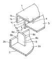
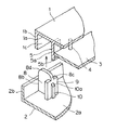
(第1の実施形態)図1および図2は、本発明に係る配線板の固定構造の第1の実施形態を示す分解斜視図および断面図である。なお、図1では、本発明の特徴部分を明快にするために、ケース1とカバー2の位置関係を図8の場合と逆に示している。
(First Embodiment) FIGS. 1 and 2 are an exploded perspective view and a cross-sectional view showing a first embodiment of a circuit board fixing structure according to the present invention. In FIG. 1, the positional relationship between the
図に示すように、合成樹脂製のケース1と、このケース1に組み付けられる合成樹脂製のカバー2とで形成される内部空間に配線板3が固定される。ケース1の底面1aには、配線板3を底面1aから一定の高さに支持するボス等の支持部材4が、一体形成で立設されている。なお、支持部材4は、図では1個のみ示されているが、配線板3を支持するのに要する複数個が適所に立設されている。
As shown in the figure, a
また、ケース1の底面1aには、支持部材4で支持された配線板3を固定するための係止爪部材5も一体形成で立設されている。なお、係止爪部材5も、図では1個のみ示されているが、配線板3を固定する複数個が適所に立設されている。係止爪部材5は、所定幅の板状部材5aからなり、その先端に係止爪5bが形成されている。
Further, a
カバー2の底面2aには、たわみ防止部材8がカバー2と一体形成で立設されている。たわみ防止部材8は、平板状に形成されている。平板の平面は、係止爪部材5を構成する板状部材5aの平面に対してほぼ直角方向をなしている。また、平板は、ケース1の外壁1bと係止爪部材5間の空間1cとほぼ同じ幅を有している。平板の一方の側部8aは、係止爪部材5のたわみを防止する規制面として作用する。さらに、平板の両側部8aおよび8bから連続して、先端側の両角を丸く削り取ったR状の誘い込み面8cおよび8dが形成されている。誘い込み面8cは、後述するケース1へのカバー2の組付状態において、係止爪部材5からたわみ防止部材8の立設方向に次第に離れるように延長して形成されている。また、誘い込み面8dは、後述するケース1へのカバー2の組付状態において、カバー2の外壁2bからたわみ防止部材8の立設方向に次第に離れるように延長して形成されている。
On the
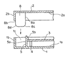
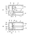
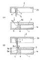
上述の構造において、図2に示すように、配線板3は、ケース1の所定位置に嵌めこまれ、係止爪部材5の係止爪5bにて係止され、支持部材4により一定の高さに固定される。その後、カバー2が矢印方向からケース1に組み付けられる。
In the structure described above, as shown in FIG. 2, the
組み付け時、図3(A)に示すように、たわみ防止部材8のR状の誘い込み面8cが、係止爪部材5の係止爪5bに接触し、係止爪5bを矢印C方向に移動させる誘い込み形状として作用する。それにより、ケース1とカバー2の組み付け時のずれや係止爪5bの変形などにより、狙いの位置に係止爪5bがない場合でも、図3(B)に示すように、たわみ防止部材8が、係止爪5bの左側の空間1cに確実に挿入される。そして、たわみ防止部材8の平板の側部8aが、配線板3の端部に係止する側と反対側の係止爪部材5の平面に接触して係止爪部材5のたわみを防止する規制面として作用し、係止爪5bを正規の位置、すなわち、配線板3の端部に係止する位置に誘導することが可能となる。このとき、誘い込み面8dも、ケース1の外壁1bに接触して空間1cへの挿入を容易にする誘い込み形状として作用する。最後に、カバー2の係止爪(図示しない)とケース1の係止部(図示しない)が組み付けられ、ケース1とカバー2の結合が完了する。
At the time of assembly, as shown in FIG. 3A, the R-
たわみ部材8の平板は、ケース1の外壁1bと係止爪部材5間の空間1cとほぼ同じ幅を有しているので、係止爪5bが配線板3がはずれる方向にたわむのをほぼ完璧に防止することができる。そして、たわみ防止部材8の先端部分を空間1cへ挿入できたとき、係止爪部材5による配線板3の固定が確実に行なわれたことを確認することができる。さらに、万一係止爪部材5の大きな変形があった場合は、係止爪5bの先端がたわみ防止部材8の先端部に当たり、カバー2はケース1に組み付かない。
The flat plate of the
したがって、正規な組み付けができたこと、誤組み付けになりそうなことを組み付け作業者が判断することができる。それにより、係止爪部材5の大きな変形がある場合にケース1を別のものに交換するなど対処することができ、従来のように誤組み付けのまま製造した機器が出荷されるようなことがなくなる。
Therefore, the assembling operator can determine that the normal assembling has been completed and that an improper assembling is likely. Thereby, when there is a large deformation of the
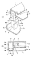
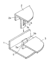
(第2の実施形態)次に、図4(A)および(B)は、それぞれ、本発明に係る配線板の固定構造の第2の実施形態を示す分解斜視図および断面図である。図4(A)に示すように、この第2の実施形態では、上述の第1の実施形態の構造に加えて、たわみ防止部材8が側板9を備えている。側板9は、たわみ防止部材8と一体形成され、係止爪部材5の板状部材5aとほぼ同じ幅と、たわみ防止部材8の誘い込み面8cの手前までの高さを有する板状に形成されている。側板9は、たわみ防止部材8の平板の側部8aと面一となると共に、たわみ防止部材8の平板とほぼ直角な平面(すなわち、係止爪部材5の平面とほぼ平行な平面)を有する。
(Second Embodiment) FIGS. 4A and 4B are an exploded perspective view and a sectional view, respectively, showing a second embodiment of a circuit board fixing structure according to the present invention. As shown in FIG. 4A, in the second embodiment, the
上述の構造においては、ケース1とカバー2の組み付け時、図4(B)に示すように、側板9は、係止爪部材5の板状部材5aの平面に接触し、その平面で板状部材5aの平面を受けるため、係止爪部材5のねじれを防止することができる。それによって、係止爪5bによる配線板3の固定を確実にすることができる。
In the above-described structure, when the
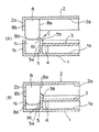
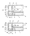
(第3の実施形態)次に、図5と図6(A)および(B)は、それぞれ、本発明に係る配線板の固定構造の第3の実施形態を示す分解斜視図および断面図である。図5に示すように、この第3の実施形態では、上述の第2の実施形態の構造に加えて、たわみ防止部材8は、側板9の平面上に一体形成されたガタつき防止リブ10を備えている。ガタつき防止リブ10は、カバー2の底面2aからたわみ防止部材8の誘い込み面8cの手前まで延長するように形成され、その先端に傾斜面10aが設けられている。
(Third Embodiment) Next, FIGS. 5, 6A and 6B are an exploded perspective view and a cross-sectional view showing a third embodiment of a wiring board fixing structure according to the present invention, respectively. is there. As shown in FIG. 5, in the third embodiment, in addition to the structure of the second embodiment described above, the
上述の構造においては、ケース1とカバー2の組み付け時、図6(A)に示すように、たわみ防止部材8の誘い込み面8cが、係止爪部材5の係止爪5bに接触して係止爪5bを矢印C方向に移動させる誘い込み形状として作用する。その後、ガタつき防止リブ10の先端の傾斜面10aが、係止爪部材5の左側に挿入され、図6(B)に示すように、係止爪5bが図中右方向に押されるようにして、たわみ防止部材8が、係止爪部材5の左側の空間1cに挿入される。それにより、組み付け完了時には、係止爪5bがガタ無く固定される。
In the above-described structure, when the
(第4の実施形態)次に、図7(A)および(B)は、それぞれ、本発明に係る配線板の固定構造の第4の実施形態を示す断面図である。図7(A)に示すように、この第4の実施形態では、上述の第2の実施形態の構造に加えて、係止爪部材5は、係止爪部材5が倒れ込むのを防止する倒れ込み防止リブ11を備えている。倒れ込み防止リブ11は、ケース1の底面1aから係止爪5bの手前まで延長するように形成され、その先端に傾斜面11aが設けられている。
(Fourth Embodiment) Next, FIGS. 7A and 7B are sectional views showing a fourth embodiment of the wiring board fixing structure according to the present invention. As shown in FIG. 7A, in the fourth embodiment, in addition to the structure of the second embodiment described above, the locking
上述の構造においては、ケース1とカバー2の組み付け時、図7(A)に示すように、たわみ防止部材8の誘い込み面8cが、係止爪部材5の係止爪5bに接触して係止爪5bを矢印C方向に移動させる誘い込み形状として作用する。その後、倒れ込み防止リブ11の先端の傾斜面11aに沿って、たわみ防止部材8が係止爪部材5の左側の空間1cに挿入される。
In the above-described structure, when the
以上の通り、本発明の実施形態について説明したが、本発明はこれに限らず、種々の変形、応用が可能である。 As mentioned above, although embodiment of this invention was described, this invention is not limited to this, A various deformation | transformation and application are possible.
たとえば、上述の第4の実施形態において、さらに、たわみ防止部材8がガタつき防止リブ10を備えていても良い。この場合は、ガタつき防止リブ10と倒れ込み防止リブ11の形成位置は、組み付け時リブ同士がぶつからないようにずらされている。
For example, in the above-described fourth embodiment, the
また、上述の実施形態では、たわみ防止部材8の誘い込み面8cおよび8dはR状に形成されているが、これに代えて、両角を直線的に削り取ったテーパー状を形成しても良い。
Further, in the above-described embodiment, the guiding
また、上述の実施形態では、たわみ防止部材8の誘い込み面8dは、平板の側部8bから連続して延長するように形成されているが、ケース1へのカバー2の組付け時に誘い込み面8cが係止爪5bに接触する前にケース1の外壁1bに接触するような形状とすることもできる。また、誘い込み面8dをたわみ防止部材8と一体形成せず、外壁2bの内側に立設させた別部材の側部から延長するものとして設けても良い。
Further, in the above-described embodiment, the
1 ケース
2 カバー
3 配線板
4 支持部材
5 係止爪部材
8 たわみ防止部材
8a 側部(規制面)
8c,8d 誘い込み面
9 側板
DESCRIPTION OF
8c, 8d Lead-in
Claims (3)
前記たわみ防止部材には、前記規制面と連続して、前記ケースへの前記カバーの組付け状態において前記係止爪部材から立設方向に次第に離れるように延長された誘い込み面が形成されている
ことを特徴とする配線板の固定構造。 A support member which is erected on the case and maintains the height of the wiring board at a fixed interval; a latching claw member which is erected on the case and engages with an end of the wiring board to fix the wiring board; and the case The latching claw member comes into contact with the latching claw member opposite to the side latched to the end of the wiring board in the assembled state of the cover to the case. In the fixing structure of the wiring board provided with a deflection preventing member having a regulating surface for preventing deflection,
The deflection preventing member is formed with a guide surface extending continuously from the locking claw member in a standing direction in a state where the cover is attached to the case, continuously with the regulation surface. A wiring board fixing structure characterized by that.
前記たわみ防止部材は、前記係止爪部材と前記ケースの外壁間の空間とほぼ同じ幅を有する平板状に形成され、該平板の側部が規制面とされている
ことを特徴とする配線板の固定構造。 In the fixing structure of the wiring board according to claim 1,
The wiring board, wherein the deflection preventing member is formed in a flat plate shape having substantially the same width as a space between the locking claw member and the outer wall of the case, and a side portion of the flat plate is a regulating surface. Fixed structure.
前記係止爪部材は、所定幅の板状部材からなり、該板状部材の先端に係止爪が一体形成されており、
前記たわみ防止部材は、前記係止爪部材の板状部材の所定幅とほぼ同じ幅を有する板状に形成されて前記係止爪部材のねじれを防止する側板をさらに有することを特徴とする配線板の固定構造。 In the fixing structure of the wiring board according to claim 1 or 2,
The locking claw member is composed of a plate member having a predetermined width, and the locking claw is integrally formed at the tip of the plate member.
The wiring is characterized in that the deflection preventing member further includes a side plate that is formed in a plate shape having a width substantially equal to a predetermined width of the plate-like member of the locking claw member and prevents the locking claw member from being twisted. Board fixing structure.
Priority Applications (1)
| Application Number | Priority Date | Filing Date | Title |
|---|---|---|---|
| JP2005317195A JP4512023B2 (en) | 2005-10-31 | 2005-10-31 | Wiring board fixing structure |
Applications Claiming Priority (1)
| Application Number | Priority Date | Filing Date | Title |
|---|---|---|---|
| JP2005317195A JP4512023B2 (en) | 2005-10-31 | 2005-10-31 | Wiring board fixing structure |
Publications (2)
| Publication Number | Publication Date |
|---|---|
| JP2007123749A true JP2007123749A (en) | 2007-05-17 |
| JP4512023B2 JP4512023B2 (en) | 2010-07-28 |
Family
ID=38147230
Family Applications (1)
| Application Number | Title | Priority Date | Filing Date |
|---|---|---|---|
| JP2005317195A Expired - Fee Related JP4512023B2 (en) | 2005-10-31 | 2005-10-31 | Wiring board fixing structure |
Country Status (1)
| Country | Link |
|---|---|
| JP (1) | JP4512023B2 (en) |
Cited By (3)
| Publication number | Priority date | Publication date | Assignee | Title |
|---|---|---|---|---|
| US8896172B2 (en) | 2008-12-12 | 2014-11-25 | Calsonic Kansei Corporation | Substrate support structure |
| US9205775B2 (en) | 2013-10-01 | 2015-12-08 | Denso International America, Inc. | Prism for light reflecting/diffusion between LED's |
| JP2017085018A (en) * | 2015-10-30 | 2017-05-18 | 富士電機株式会社 | Power converter |
Citations (5)
| Publication number | Priority date | Publication date | Assignee | Title |
|---|---|---|---|---|
| JPH01176986U (en) * | 1988-05-31 | 1989-12-18 | ||
| JPH0722585U (en) * | 1993-09-28 | 1995-04-21 | アイワ株式会社 | Board mounting device |
| JPH1070381A (en) * | 1996-08-27 | 1998-03-10 | Yazaki Corp | Wiring board fixing structure |
| JP2001044667A (en) * | 1999-07-28 | 2001-02-16 | Matsushita Electric Works Ltd | Electric information equipment |
| JP2005079236A (en) * | 2003-08-29 | 2005-03-24 | Optrex Corp | Substrate-fixing device |
-
2005
- 2005-10-31 JP JP2005317195A patent/JP4512023B2/en not_active Expired - Fee Related
Patent Citations (5)
| Publication number | Priority date | Publication date | Assignee | Title |
|---|---|---|---|---|
| JPH01176986U (en) * | 1988-05-31 | 1989-12-18 | ||
| JPH0722585U (en) * | 1993-09-28 | 1995-04-21 | アイワ株式会社 | Board mounting device |
| JPH1070381A (en) * | 1996-08-27 | 1998-03-10 | Yazaki Corp | Wiring board fixing structure |
| JP2001044667A (en) * | 1999-07-28 | 2001-02-16 | Matsushita Electric Works Ltd | Electric information equipment |
| JP2005079236A (en) * | 2003-08-29 | 2005-03-24 | Optrex Corp | Substrate-fixing device |
Cited By (3)
| Publication number | Priority date | Publication date | Assignee | Title |
|---|---|---|---|---|
| US8896172B2 (en) | 2008-12-12 | 2014-11-25 | Calsonic Kansei Corporation | Substrate support structure |
| US9205775B2 (en) | 2013-10-01 | 2015-12-08 | Denso International America, Inc. | Prism for light reflecting/diffusion between LED's |
| JP2017085018A (en) * | 2015-10-30 | 2017-05-18 | 富士電機株式会社 | Power converter |
Also Published As
| Publication number | Publication date |
|---|---|
| JP4512023B2 (en) | 2010-07-28 |
Similar Documents
| Publication | Publication Date | Title |
|---|---|---|
| JP2011129459A (en) | Insertion-coupling guide member of electrical connector and electrical connector device having the same | |
| KR20090117979A (en) | connector | |
| US20150165982A1 (en) | Attaching structure for vehicle-mounted equipment | |
| CN104968534A (en) | Structure for joining resin parts and bumper cover structure | |
| JP4512023B2 (en) | Wiring board fixing structure | |
| JP4871830B2 (en) | Engagement structure that connects two members | |
| JP2009117152A (en) | Surface mount connector | |
| JP5775334B2 (en) | Mounting member mounting structure | |
| JP6546699B2 (en) | clip | |
| JP2007234335A (en) | Fixing member and assembly structure of fixing member | |
| JP4970304B2 (en) | Two-part assembly structure | |
| JP4950674B2 (en) | clip | |
| US20130069296A1 (en) | Printed substrate holding device | |
| JP5284233B2 (en) | Structure of screw body mounting portion and wiring device mounting body | |
| JP7230222B2 (en) | Fastener | |
| JP2013045608A (en) | Connector fixing structure | |
| JP5691803B2 (en) | Connector and electrical junction box | |
| JP2009228839A (en) | Component mounting structure | |
| JP5319474B2 (en) | Wiring fixture mounting device | |
| JP6491692B2 (en) | Circuit board housing case and electronic device | |
| US7654852B2 (en) | Connector and connector assembling system | |
| JP5448633B2 (en) | connector | |
| JP6054160B2 (en) | Mounting structure of the slider to the mounted body | |
| JP5144405B2 (en) | Connector housing with latch | |
| JP5186288B2 (en) | Wire harness retaining clip |
Legal Events
| Date | Code | Title | Description |
|---|---|---|---|
| A621 | Written request for application examination |
Free format text: JAPANESE INTERMEDIATE CODE: A621 Effective date: 20080206 |
|
| A977 | Report on retrieval |
Free format text: JAPANESE INTERMEDIATE CODE: A971007 Effective date: 20100114 |
|
| A131 | Notification of reasons for refusal |
Free format text: JAPANESE INTERMEDIATE CODE: A131 Effective date: 20100119 |
|
| A521 | Written amendment |
Free format text: JAPANESE INTERMEDIATE CODE: A523 Effective date: 20100316 |
|
| TRDD | Decision of grant or rejection written | ||
| A01 | Written decision to grant a patent or to grant a registration (utility model) |
Free format text: JAPANESE INTERMEDIATE CODE: A01 Effective date: 20100420 |
|
| A01 | Written decision to grant a patent or to grant a registration (utility model) |
Free format text: JAPANESE INTERMEDIATE CODE: A01 |
|
| A61 | First payment of annual fees (during grant procedure) |
Free format text: JAPANESE INTERMEDIATE CODE: A61 Effective date: 20100507 |
|
| FPAY | Renewal fee payment (event date is renewal date of database) |
Free format text: PAYMENT UNTIL: 20130514 Year of fee payment: 3 |
|
| R150 | Certificate of patent or registration of utility model |
Ref document number: 4512023 Country of ref document: JP Free format text: JAPANESE INTERMEDIATE CODE: R150 Free format text: JAPANESE INTERMEDIATE CODE: R150 |
|
| FPAY | Renewal fee payment (event date is renewal date of database) |
Free format text: PAYMENT UNTIL: 20140514 Year of fee payment: 4 |
|
| R250 | Receipt of annual fees |
Free format text: JAPANESE INTERMEDIATE CODE: R250 |
|
| R250 | Receipt of annual fees |
Free format text: JAPANESE INTERMEDIATE CODE: R250 |
|
| R250 | Receipt of annual fees |
Free format text: JAPANESE INTERMEDIATE CODE: R250 |
|
| R250 | Receipt of annual fees |
Free format text: JAPANESE INTERMEDIATE CODE: R250 |
|
| R250 | Receipt of annual fees |
Free format text: JAPANESE INTERMEDIATE CODE: R250 |
|
| LAPS | Cancellation because of no payment of annual fees |