JP2007113206A - Mounting structure of ceiling substrate member - Google Patents
Mounting structure of ceiling substrate member Download PDFInfo
- Publication number
- JP2007113206A JP2007113206A JP2005303507A JP2005303507A JP2007113206A JP 2007113206 A JP2007113206 A JP 2007113206A JP 2005303507 A JP2005303507 A JP 2005303507A JP 2005303507 A JP2005303507 A JP 2005303507A JP 2007113206 A JP2007113206 A JP 2007113206A
- Authority
- JP
- Japan
- Prior art keywords
- clip
- field edge
- ceiling
- edge receiving
- receiving material
- Prior art date
- Legal status (The legal status is an assumption and is not a legal conclusion. Google has not performed a legal analysis and makes no representation as to the accuracy of the status listed.)
- Granted
Links
Images


Landscapes
- Connection Of Plates (AREA)
Abstract
Description
本発明は、天井ボードを固定する天井下地部材の取付け構造に関する。 The present invention relates to a mounting structure for a ceiling base member for fixing a ceiling board.
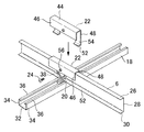
従来、特許文献1に記載の天井下地部材の取付け構造は図5に示すように、建物天井の下地に用いられる天井の野縁材2を、ハンガー4によって吊り下げられた野縁受け材6にクリップ8を用いて係止する構造であり、この野縁材2にビス等を用いて内装材としての天井ボード10を取付ける。
Conventionally, as shown in FIG. 5, the ceiling base member mounting structure described in Patent Document 1 is used to replace a ceiling
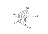
上記野縁材2は、略チャンネル形状の長尺材であり、この両側板部の上端は、緩く内側方向から下方向きに折曲した屈曲部12,12が向かい合う状態で形成されている。上記クリップ8は図6に示すように、縦状の基板部14の下部の両側に上方に向けて屈曲形成された係止片15が形成されている。基板部14の上端部には、3本の爪片からなる爪片部16が横向きに屈曲形成されている。
The
上記野縁受け材6と野縁材2が交差した位置において、野縁材2の屈曲部12,12にクリップ8の係止片15を係止させ、かつこのクリップ8の基板部14を野縁受け材6の側部に当てた状態で、野縁受け材6の上面部の上部に配置される爪片部16を、野縁受け材6を囲む状態で下方に折り曲げて、野縁受け材6に固定する。このようにクリップ8は、野縁材2を野縁受け材6に取り付ける時に、クリップ8の爪片部16を折り曲げることで容易に取り付け作業が行える。
At the position where the field
さて、上記天井下地部材の取付け構造では、上記クリップ8の爪片部16を折り曲げてクリップ8を野縁受け材6に係着させる構造であるため、地震等の揺れにより上記爪片部16の折り曲げた係着箇所が緩み、このため揺れの程度によってはクリップ8が野縁受け材6から外れるおそれがあるという問題があった。
Now, in the mounting structure of the ceiling base member, the
本発明は、上記問題点に鑑みてなされたものであり、揺れ等の振動に対しても十分な強度が維持できる天井下地部材の取付け構造を提供することを目的としている。 The present invention has been made in view of the above problems, and an object of the present invention is to provide a ceiling base member mounting structure that can maintain sufficient strength against vibrations such as shaking.
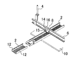
以上の技術的課題を解決するため、本発明に係る天井下地部材の取付け構造は、図1,2に示すように、建物天井に水平に吊り下げられた野縁受け材6と、上記野縁受け材の下部に、この野縁受け材と交差する方向に配置される天井の野縁材18と、上記野縁材を取り付ける接続部40が下部に設けられた縦板状の基板部38、及びこの基板部から上記野縁受け材の上部を経て、この野縁受け材の側部にいたる爪片部42を有し、上記野縁材を上記野縁受け材に取り付けるクリップ20と、上記野縁受け材の一方の側部に被される上記クリップを狭持する一方の縦板部46、野縁受け材の上面部を被う上記クリップの上部に位置する上板部44、野縁受け板の他方の側部を保持する他方の縦板部48を有し、上記一方の縦板部にはビスを螺着して圧着固定するための螺子孔56が設けられ、上記野縁受け材に取り付けられる上記クリップの基板部及び爪片部を、上記野縁受けとともに挟む状態で保持するクリップ保持具22と、を有する構成である。
In order to solve the above technical problems, the ceiling base member mounting structure according to the present invention includes a field
本発明に係る天井下地部材の取付け構造において、上記クリップ保持具22は、上記他方の縦板部の左右部から、それぞれ下方に延設され、かつ内側に屈曲する係合部54が形成された構成である。
In the ceiling base member mounting structure according to the present invention, the
本発明に係る天井下地部材の取付け構造によれば、野縁受け材の下部に交差する方向に配置される野縁材、縦板状の基板部及び爪片部を有し野縁材を野縁受け材に取り付けるクリップ、このクリップを野縁受けとともに挟む状態で保持するクリップ保持具を有する構成を採用したから、クリップの保持が確実に行え、地震等による揺れ、振動によってもクリップが野縁受け材から外れることがなく、また取り付けも簡単で天井下地部材の取付けが強固に行えるという効果がある。 According to the ceiling base member mounting structure according to the present invention, a field edge material having a field edge material, a vertical plate-like substrate portion, and a claw piece portion arranged in a direction intersecting the lower portion of the field edge receiving material is provided. The clip has a clip that is attached to the edge receiving material and a clip holder that holds the clip with the edge holder. There is an effect that the ceiling base member can be firmly attached without being detached from the receiving material and being easy to attach.
本発明に係る天井下地部材の取付け構造によれば、クリップ保持具は、他方の縦板部から延設される係合部を設けたから、クリップ保持具の装着が確実に行え、クリップの保持が安定するという効果がある。 According to the ceiling base member mounting structure according to the present invention, since the clip holder is provided with the engaging portion extending from the other vertical plate portion, the clip holder can be securely attached and the clip can be held. It has the effect of stabilizing.
以下、本発明に係る天井下地部材の取付け構造の実施の形態を図面に基づいて説明する。
図1は、天井下地部材の取付け構造を示したものであり、天井に吊り下げられた水平状の野縁受け材6、この野縁受け材6とは直交方向に配置される天井の野縁材18、野縁材18を野縁受け材6に取り付けるクリップ20、さらにこのクリップ20を保持するクリップ保持具22及びビス24を有する。
DESCRIPTION OF EMBODIMENTS Hereinafter, an embodiment of a ceiling base member mounting structure according to the present invention will be described with reference to the drawings.
FIG. 1 shows a mounting structure for a ceiling base member, a horizontal
上記野縁受け材6は、上面部26、側面部28及び下面部30を有するチャンネル状(断面コの字)の長尺材であり、鋼板又はステンレス板からなる。上記野縁材18は、略チャンネル形状の長尺材であり、これは底部32とこの底部32の両側端から立ち上がる左右の側部34,34を有し、両側部34,34の上端には、それぞれ内向きから下方に向け鉤状に屈曲する屈曲部36,36が向かい合う状態で形成されている。この野縁材18の材料としては、鋼材或いは軽量金属等が用いられる。
The field
上記クリップ20は図2に示すように、縦向きの基板部38、この基板部38の下部の両側に上方に向けて屈曲形成された係止片40,40、及び基板部38の上端部には、2本の爪片を有する爪片部42が横向きに屈曲形成されている。また上記基板部38の中央部付近は、補強のためのリブが膨出形成されている。上記係止片40,40は、野縁材18の屈曲部36,36に係着するクリップ20の接続部として機能する。
As shown in FIG. 2, the
上記クリップ保持具22は図1,3に示すように、野縁受け材6の上面部26の上部を被う上板部44、この上板部44の一方側から下方に屈曲形成された一方の縦板部46、上記上板部44の他方側から下方に屈曲形成された他方の縦板部48を有する。上記他方の縦板部48の下部には、それぞれ左右の部位から下方に延設され、さらに内側に鉤状に屈曲した係合片52を有する係合部54,54が設けられている。
As shown in FIGS. 1 and 3, the
そして、上記係合部54,54間には、所定の幅(W)の開口部50が形成されている。この開口部50の幅(W)の寸法は、上記野縁材18の幅寸法より広く、ここでは略2倍に形成されている。これは、上記野縁材18の2倍の幅寸法を有する野縁材もあるので、この野縁材を用いた場合であっても、当該クリップ保持具22の使用が可能なように汎用性をもたせている。また、上記一方の縦板部46の中央の下部寄りの位置には、バーリング加工による螺子孔56が形成されている。
An opening 50 having a predetermined width (W) is formed between the
施工の際には、上記図5に示すように、建物天井から吊り下げられたハンガー4によって、野縁受け材6を掛着し、所定の間隔をおいて平行状かつ水平に上記野縁受け材6を配設する。そして、上記野縁受け材6と直交する向きに野縁材18を配置し、クリップ20を用いて野縁受け材6に野縁材18を取り付ける。
At the time of construction, as shown in FIG. 5, the field
このとき、図2に示すように、クリップ20の係止片40を野縁材18のチャンネル状の溝内に突入させ、クリップ20を回して係止片40を野縁材18の屈曲部36に係止させる。そして、上記クリップ20の基板部38を、野縁材18と交差する野縁受け材6の側部に当接させ、この状態で野縁受け材6の上面部26の上部に位置するクリップ20の爪片部42を下方に折り曲げ、クリップ20を野縁受け材6に固定する。このクリップ20の野縁受け材6への固定により、クリップ20の係止片40は野縁材18の屈曲部36に突入して係止状態が維持される。
At this time, as shown in FIG. 2, the
さらに図1に示すように、上記クリップ保持具22を、上記野縁受け材6に固定したクリップ20の外部を覆う状態で野縁受け材6に被着する。このとき、クリップ保持具22をクリップ20の爪片部42の上面部方向から挿入し、クリップ20とともに野縁受け材6の下面部30にクリップ保持具22の係合片52が入りこむようにして係合する。
Further, as shown in FIG. 1, the
そして、クリップ保持具22のビス孔56にビス24を螺着締結し、クリップ保持具22の圧着固定を強固にする。この状態で、クリップ保持具22の他方の縦板部48がクリップ20とともに野縁受け材6の側部を保持し、かつ一方の縦板部46がクリップ20とともに野縁受け材6の側部を狭持する。また上記ビス24により、クリップ20に設けられているリブがこのビス24に当接してクリップ20が強固に締結される。このクリップ保持具22により、クリップ20の基板部38及び屈曲された爪片部42が押圧、拘束されるので、揺れ等の振動によってクリップ20が野縁受け材6から外れることはない。
Then, the
図4は、クリップ保持具22の他の取り付け形態を示したものである。ここでは、クリップ保持具22の向きの前後を逆にし、この状態で上記実施の形態と同様に、クリップ保持具22をクリップ20を介して野縁受け材6に被着する。そして、クリップ保持具22のビス孔56にビス24を螺着締結し、クリップ保持具22の圧着固定を強固にする。
FIG. 4 shows another attachment form of the
このとき、クリップ保持具22の他方の縦板部48がクリップ20とともに野縁受け材6の側部を保持し、かつ一方の縦板部46がクリップ20とともに野縁受け材6の側部を狭持する。この場合も、クリップ保持具22により、クリップ20の基板部38及び屈曲された爪片部42が押圧、拘束され、振動等によってクリップ20が野縁受け材6から外れることはない。
At this time, the other
従って、上記天井下地部材の取付け構造によれば、クリップ保持具によりクリップの保持が安定かつ確実に行えるので、地震等の揺れ、振動によってもクリップが野縁受け材から外れることがなく、また取り付けも簡単で天井下地部材の取付けが強固に行えるという効果がある。また、上記クリップを用いて野縁材を野縁受け材に取り付けた構造の、既存の天井下地材の改修補強にも利用することができるものである。 Therefore, according to the ceiling base member mounting structure, the clip holder can hold the clip stably and reliably, so that the clip is not detached from the edge receiving material due to shaking or vibration such as an earthquake. It is also simple and has an effect that the ceiling base member can be firmly attached. Moreover, it can utilize also for the repair reinforcement of the existing ceiling base material of the structure which attached the field material to the field edge receiving material using the said clip.
2,18 野縁材
6 野縁受け材
8,20 クリップ
22 クリップ保持具
24 ビス
38 基板部
40 接続部(係止片)
42 爪片部
44 上板部
46 一方の縦板部
48 他方の縦板部
52 係合片
54 係合部
56 螺子孔
2,18
42
Claims (2)
上記野縁受け材の下部に、この野縁受け材と交差する方向に配置される天井の野縁材と、
上記野縁材を取り付ける接続部が下部に設けられた縦板状の基板部、及びこの基板部から上記野縁受け材の上部を経て、この野縁受け材の側部にいたる爪片部を有し、上記野縁材を上記野縁受け材に取り付けるクリップと、
上記野縁受け材の一方の側部に被される上記クリップを狭持する一方の縦板部、野縁受け材の上面部を被う上記クリップの上部に位置する上板部、野縁受け板の他方の側部を保持する他方の縦板部を有し、上記一方の縦板部にはビスを螺着して圧着固定するための螺子孔が設けられ、上記野縁受け材に取り付けられる上記クリップの基板部及び爪片部を、上記野縁受けとともに挟む状態で保持するクリップ保持具と、を有することを特徴とする天井下地部材の取付け構造。 A field edge receiving material suspended horizontally on the ceiling of the building,
In the lower part of the field edge receiving material, the field edge material of the ceiling arranged in a direction intersecting with the field edge receiving material,
A vertical plate-like substrate part provided with a connection part to which the field edge material is attached at the lower part, and a claw piece extending from this board part to the side part of the field edge receiving material through the upper part of the field edge receiving material. A clip for attaching the field edge material to the field edge receiving material;
One vertical plate portion that holds the clip that covers the one side of the field edge receiving material, an upper plate portion that is positioned above the clip that covers the upper surface portion of the field edge receiving material, and a field edge receiving device It has the other vertical plate part that holds the other side part of the plate, and the one vertical plate part is provided with a screw hole for screwing and fixing the screw, and is attached to the field receiving member. And a clip holder for holding the base plate portion and the claw piece portion of the clip in a state of being sandwiched together with the field receiver.
Priority Applications (1)
| Application Number | Priority Date | Filing Date | Title |
|---|---|---|---|
| JP2005303507A JP4782536B2 (en) | 2005-10-18 | 2005-10-18 | Ceiling base member mounting structure |
Applications Claiming Priority (1)
| Application Number | Priority Date | Filing Date | Title |
|---|---|---|---|
| JP2005303507A JP4782536B2 (en) | 2005-10-18 | 2005-10-18 | Ceiling base member mounting structure |
Publications (2)
| Publication Number | Publication Date |
|---|---|
| JP2007113206A true JP2007113206A (en) | 2007-05-10 |
| JP4782536B2 JP4782536B2 (en) | 2011-09-28 |
Family
ID=38095653
Family Applications (1)
| Application Number | Title | Priority Date | Filing Date |
|---|---|---|---|
| JP2005303507A Active JP4782536B2 (en) | 2005-10-18 | 2005-10-18 | Ceiling base member mounting structure |
Country Status (1)
| Country | Link |
|---|---|
| JP (1) | JP4782536B2 (en) |
Cited By (2)
| Publication number | Priority date | Publication date | Assignee | Title |
|---|---|---|---|---|
| JP2016035142A (en) * | 2014-08-01 | 2016-03-17 | 八潮建材工業株式会社 | Connection member and application method of ceiling base member |
| JP2016044459A (en) * | 2014-08-22 | 2016-04-04 | 常盤工業株式会社 | Hanging ceiling structure and metal fitting thereof |
Citations (1)
| Publication number | Priority date | Publication date | Assignee | Title |
|---|---|---|---|---|
| JP2007023738A (en) * | 2005-07-21 | 2007-02-01 | Okuju Co Ltd | Connection reinforcing implement for furring-strips retainer and furring strips, and method for reinforcing ceiling substrate |
-
2005
- 2005-10-18 JP JP2005303507A patent/JP4782536B2/en active Active
Patent Citations (1)
| Publication number | Priority date | Publication date | Assignee | Title |
|---|---|---|---|---|
| JP2007023738A (en) * | 2005-07-21 | 2007-02-01 | Okuju Co Ltd | Connection reinforcing implement for furring-strips retainer and furring strips, and method for reinforcing ceiling substrate |
Cited By (2)
| Publication number | Priority date | Publication date | Assignee | Title |
|---|---|---|---|---|
| JP2016035142A (en) * | 2014-08-01 | 2016-03-17 | 八潮建材工業株式会社 | Connection member and application method of ceiling base member |
| JP2016044459A (en) * | 2014-08-22 | 2016-04-04 | 常盤工業株式会社 | Hanging ceiling structure and metal fitting thereof |
Also Published As
| Publication number | Publication date |
|---|---|
| JP4782536B2 (en) | 2011-09-28 |
Similar Documents
| Publication | Publication Date | Title |
|---|---|---|
| JP5702264B2 (en) | Field edge mounting structure | |
| JP2008542645A (en) | Sheet metal fasteners and clips | |
| JP4745844B2 (en) | Hanging bolt steady rest device | |
| JP6214041B2 (en) | Suspended ceiling structure | |
| JP2010229785A (en) | Fixing clip | |
| JP4782536B2 (en) | Ceiling base member mounting structure | |
| JP5769529B2 (en) | Clip material for ceiling base | |
| KR101443558B1 (en) | Bracket for screen louver | |
| JP3131651U (en) | Hanger | |
| JP2009074305A (en) | Fixing metal fitting for bracing backing material | |
| JP2011196391A (en) | Support for body to be disposed | |
| JP4888774B2 (en) | Mounting bracket for base material for steady rest | |
| JP5635899B2 (en) | Goby fittings | |
| KR20190010205A (en) | Ceiling finish apparatus having vibration isolation function and ceiling finish method using the same | |
| JP3198050U (en) | Hanging bracket for ceiling edge holder | |
| JP2018031178A (en) | Ceiling joist fitting device | |
| JP2005261802A (en) | Wall hanging tool | |
| JP5044460B2 (en) | Fixing member for wiring box | |
| JP5117870B2 (en) | Eaves support | |
| JP4237927B2 (en) | Field edge mounting structure | |
| JP5107734B2 (en) | Eaves support | |
| JP3163512B2 (en) | Connection structure of ceiling bar | |
| JP2012026095A (en) | Runner fixing metallic material | |
| JP2017155838A (en) | Hanger support tool | |
| JP2020111984A (en) | Fixture for roof |
Legal Events
| Date | Code | Title | Description |
|---|---|---|---|
| A621 | Written request for application examination |
Free format text: JAPANESE INTERMEDIATE CODE: A621 Effective date: 20080918 |
|
| A977 | Report on retrieval |
Free format text: JAPANESE INTERMEDIATE CODE: A971007 Effective date: 20110303 |
|
| A131 | Notification of reasons for refusal |
Free format text: JAPANESE INTERMEDIATE CODE: A131 Effective date: 20110315 |
|
| A521 | Request for written amendment filed |
Free format text: JAPANESE INTERMEDIATE CODE: A523 Effective date: 20110328 |
|
| TRDD | Decision of grant or rejection written | ||
| A01 | Written decision to grant a patent or to grant a registration (utility model) |
Free format text: JAPANESE INTERMEDIATE CODE: A01 Effective date: 20110607 |
|
| A01 | Written decision to grant a patent or to grant a registration (utility model) |
Free format text: JAPANESE INTERMEDIATE CODE: A01 |
|
| A61 | First payment of annual fees (during grant procedure) |
Free format text: JAPANESE INTERMEDIATE CODE: A61 Effective date: 20110707 |
|
| FPAY | Renewal fee payment (event date is renewal date of database) |
Free format text: PAYMENT UNTIL: 20140715 Year of fee payment: 3 |
|
| R150 | Certificate of patent or registration of utility model |
Ref document number: 4782536 Country of ref document: JP Free format text: JAPANESE INTERMEDIATE CODE: R150 Free format text: JAPANESE INTERMEDIATE CODE: R150 |
|
| R250 | Receipt of annual fees |
Free format text: JAPANESE INTERMEDIATE CODE: R250 |
|
| R250 | Receipt of annual fees |
Free format text: JAPANESE INTERMEDIATE CODE: R250 |
|
| R250 | Receipt of annual fees |
Free format text: JAPANESE INTERMEDIATE CODE: R250 |
|
| R250 | Receipt of annual fees |
Free format text: JAPANESE INTERMEDIATE CODE: R250 |
|
| R250 | Receipt of annual fees |
Free format text: JAPANESE INTERMEDIATE CODE: R250 |
|
| R250 | Receipt of annual fees |
Free format text: JAPANESE INTERMEDIATE CODE: R250 |
|
| R250 | Receipt of annual fees |
Free format text: JAPANESE INTERMEDIATE CODE: R250 |
|
| R250 | Receipt of annual fees |
Free format text: JAPANESE INTERMEDIATE CODE: R250 |
|
| R250 | Receipt of annual fees |
Free format text: JAPANESE INTERMEDIATE CODE: R250 |
|
| R250 | Receipt of annual fees |
Free format text: JAPANESE INTERMEDIATE CODE: R250 |