JP2007111904A - Liquid delivering head and its manufacturing method - Google Patents
Liquid delivering head and its manufacturing method Download PDFInfo
- Publication number
- JP2007111904A JP2007111904A JP2005303238A JP2005303238A JP2007111904A JP 2007111904 A JP2007111904 A JP 2007111904A JP 2005303238 A JP2005303238 A JP 2005303238A JP 2005303238 A JP2005303238 A JP 2005303238A JP 2007111904 A JP2007111904 A JP 2007111904A
- Authority
- JP
- Japan
- Prior art keywords
- adhesive
- light
- irradiated
- transferred
- head body
- Prior art date
- Legal status (The legal status is an assumption and is not a legal conclusion. Google has not performed a legal analysis and makes no representation as to the accuracy of the status listed.)
- Withdrawn
Links
Images


Abstract
Description
本発明は複写機、ファクシミリ、ワープロ、ホストコンピューター等の出力用 端末としてのプリンタ、ビデオプリンタ等に用いられるインクジェット記録ヘッドに関する。特に、インク吐出エネルギーとして熱エネルギーを発生する発熱体(電気熱変換素子)を形成した基板を有し、記録用のインクを飛翔液滴として吐出口(オリフィス)から吐出させて、記録媒体に付着させることによって記録を行う液体吐出ヘッドに関する。 The present invention relates to an ink jet recording head used in printers, video printers, and the like as output terminals of copying machines, facsimiles, word processors, host computers and the like. In particular, it has a substrate on which a heating element (electrothermal conversion element) that generates thermal energy as ink ejection energy is formed, and ink for recording is ejected from the ejection port (orifice) as flying droplets and adheres to the recording medium It is related with the liquid discharge head which records by making it.
尚、本発明における「記録」とは、文字や図形等の意味を持つ画像を被記録媒体に形成することだけでなく、意味を持たないパターン等の画像を形成することも含む。 Note that “recording” in the present invention includes not only forming an image having a meaning such as a character or a figure on a recording medium but also forming an image such as a pattern having no meaning.
従来、液体吐出ヘッドを用いて記録を行う方法は、ノンインパクト記録であり、騒音が小さく、高密度化、高速印字が可能であること、保守が比較的簡単でメンテナンスフリーになり得るなどの理由から、近年、多用されている。 Conventionally, the method of recording using a liquid discharge head is non-impact recording, with low noise, high density, high-speed printing possible, maintenance is relatively easy and can be maintenance-free, etc. In recent years, it has been widely used.
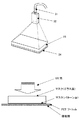
従来のこの種の液体吐出ヘッドの一例について図6を参照して説明する。 An example of this type of conventional liquid discharge head will be described with reference to FIG.
図6に示す液体吐出ヘッドは、インクを吐出するためのエネルギーを発生するエネルギー発生素子である発熱素子1005とインク流路1006を構成する溝が複数個並列に設けられた基板1001と、インク供給口が形成された天板1002と、これら基板1001及び天板1002の端面と接合され、インクを吐出するためのオリフィス1012が上記液流路1006と連通する位置に形成されたオリフィスプレート1004とを有する。
The liquid discharge head shown in FIG. 6 includes a
オリフィスプレートは1004に形成されるオリフィス1012は非常に微細なものであり、このオリフィス1012が液体吐出ヘッドの吐出特性を左右する重要な要素の一つとなっている。すなわち、液体吐出ヘッドのオリフィスプレート1004は、微細なオリフィス1012が形成されることから加工性に優れ、また、インクに直接接触するものであるから耐インク性がよいことが必要とされる。
The
このオリフィスプレートとヘッド本体の接合は接着剤を用いて行われる。 The orifice plate and the head body are joined using an adhesive.
接着剤としては熱硬化型又はUV硬化型又は熱、UV併用硬化型の接着剤が用いられ、オリフィスプレートあるいはヘッド本体に接着剤を転写し、お互いを貼り合せた後、熱を加えて又はUV光を照射して接着剤を硬化させ、接合を完了させるものである。 As the adhesive, a thermosetting type, UV curable type, heat, or UV combined type curable adhesive is used. After the adhesive is transferred to the orifice plate or the head body and bonded together, heat is applied or UV is applied. The adhesive is cured by irradiating light to complete the bonding.
従来例としては、例えば特許文献1をあげることが出来る。
しかしながら、従来の液体吐出ヘッドには以下に示す問題点があった。 However, the conventional liquid discharge head has the following problems.
オリフィスプレートあるいはヘッド本体に接着剤を転写し、貼り合せた際、転写されていた接着剤がヘッド本体の流路壁のエッジを伝わり流路内へ流れ込んでしまう。流れ込んだ接着剤は流路壁後端に溜まってマッチ棒の様な形状になり、さらには流路を塞いでしまい吐出に影響を与える。 When the adhesive is transferred to the orifice plate or the head main body and bonded, the transferred adhesive flows along the edge of the flow path wall of the head main body and flows into the flow path. The adhesive that has flowed in accumulates at the rear end of the flow path wall and has a shape like a match rod, and further blocks the flow path and affects the discharge.
また、ヒーター上に可動部材がある場合にはヒーターと可動部材の隙間を接着剤で埋めてしまい、ヒーター及び可動部材が機能しなくなり、良好な吐出が行えなくなってしまう。 In addition, when there is a movable member on the heater, the gap between the heater and the movable member is filled with an adhesive, and the heater and the movable member do not function, and good discharge cannot be performed.
接着剤の粘度を変えることにより流動性を悪化させ、接着剤の流れ込みを防ぐ方法もあるが、粘度を高めると、接着剤自体の薄膜化が困難であり、厚膜の接着剤を転写することになってしまい、多量に接着剤が流路先端に入り込んでしい、これも良好な吐出が行えなくなってしまう。 There is a method to prevent the adhesive from flowing by changing the viscosity of the adhesive, but if the viscosity is increased, it is difficult to reduce the thickness of the adhesive itself. As a result, a large amount of the adhesive enters the end of the flow path, which also makes it impossible to perform good discharge.
UV硬化型又はUV、熱併用硬化型の接着剤を用い、あらかじめUV光を接着剤に 照射させ硬化反応を開始させることで流動性を悪化させてから転写し、貼り合せる方法においては、接着信頼性(耐インク性)が低下してしまい、インクがオリフィスプレートとヘッド本体の接着剤界面に染み出して混色したり、吐出に影響をおよぼしたりする。 In the method of using UV curing type or UV and heat combined curing type adhesives, irradiating UV light to the adhesive in advance to start the curing reaction, and then transferring and pasting, the adhesion reliability As a result, the ink (ink resistance) deteriorates, and the ink oozes out to the adhesive interface between the orifice plate and the head main body and mixes colors or affects ejection.
そこで本発明はオリフィスプレートとヘッド本体を接着剤にて貼り合せ、硬化させる際に流路内へ多量に流れ込む接着剤に起因する吐出不良及び、接着信頼性を確保した液体吐出ヘッドを提供することを目的とする。 Accordingly, the present invention provides a liquid ejection head that ensures ejection failure and adhesion reliability due to an adhesive that flows in a large amount into a flow path when an orifice plate and a head body are bonded together and cured. With the goal.
インクを吐出させるために利用されるエネルギーを発生するエネルギー素子を備え、互いに平行に配列された複数のインク流路が端面に開口するヘッド本体と各インク流路に対応する部位にそれぞれ各インク流路と連通するオリフィスを有するオリフィスプレートをヘッド本体にUV硬化型又はUV及び熱硬化型接着剤を転写した後、貼り合せる液体吐出ヘッドにおいて、UV光を照射した部分と照射しない部分が存在する接着剤を転写し、貼り合せることを特徴とする。 Each of the ink flow paths includes an energy element that generates energy used for ejecting ink, and a plurality of ink flow paths arranged in parallel to each other at a head body that opens at an end surface and a portion corresponding to each ink flow path. Adhesion of the part that is irradiated with UV light and the part that is not irradiated in the liquid discharge head that is bonded after transferring the UV curable adhesive or UV and thermosetting adhesive to the head body with the orifice plate that has the orifice communicating with the path It is characterized in that the agent is transferred and bonded.
(作用)
接着剤に対し微量なUV光を照射した部分(半生部)とUV光を照射していない部分(生部)を作り出し、その後転写し、貼り合せる。
(Function)
Create a part of the adhesive that has been exposed to a small amount of UV light (semi-lived part) and a part that has not been irradiated with UV light (raw part), and then transfer and paste them together.
そうすることで、半生部の接着剤は流動性が悪くなっているため生部の接着剤の流動をある程度、ブロックしてくれる。 By doing so, the adhesive in the semi-finished part has a poor fluidity, and therefore blocks the flow of the adhesive in the raw part to some extent.
そのため、流路内への接着剤の多量な流れ込みを防ぐことができる。 Therefore, a large amount of adhesive can be prevented from flowing into the flow path.
また、転写全領域を半生化させた接着剤に比べ、生部の接着剤が存在するため、接着信頼性(耐インク性)も向上させることができる。 In addition, since the adhesive in the green part is present compared to the adhesive in which the entire transfer area is semi-finished, the adhesion reliability (ink resistance) can be improved.
本発明はオリフィスプレートとヘッド本体を接合する際の接着剤にあらかじめ部分的にUV光を照射し、その後、転写するものである。 In the present invention, UV light is partially irradiated in advance to the adhesive used to join the orifice plate and the head body, and then transferred.
UV光を照射した部分は接着剤の流動性が悪化する。 The fluidity of the adhesive deteriorates in the part irradiated with UV light.
そのため、接着剤の多量な流路内への流れ込みを防ぐことができ、良好な吐出が行え、液体吐出ヘッドの歩留りを大幅に改善することができた。 Therefore, it was possible to prevent a large amount of adhesive from flowing into the flow path, perform good discharge, and greatly improve the yield of the liquid discharge head.
また、接着剤にはUV光を照射していない部分も存在するため、接着信頼性(耐インク性)も確保でき、接着剤界面へのインクの染み出しによる混色、インク漏れ等も防ぐことができた。 In addition, since there are parts that are not irradiated with UV light, adhesive reliability (ink resistance) can be secured, and color mixing and ink leakage due to ink oozing out to the adhesive interface can be prevented. did it.
本実施の形態は図1に示すように、液体を吐出させるためのエネルギー素子を備えた基板(11)上に感光性樹脂をパターニングして流路壁、液室枠を形成した。 In the present embodiment, as shown in FIG. 1, a photosensitive resin is patterned on a substrate (11) provided with an energy element for discharging a liquid to form a flow path wall and a liquid chamber frame.
流路壁上方にインク供給口及び流路の一部を形成する天板(12)を接着剤により接合しヘッド本体(13)を形成させた。 A head body (13) was formed by bonding an ink supply port and a top plate (12) forming a part of the flow path above the flow path wall with an adhesive.
オリフィスプレート(15)には加工性、耐インク性の観点から、ポリサルフォンを用いレーザー加工にてオリフィス(14)を形成した。 From the viewpoint of processability and ink resistance, the orifice plate (15) was formed with an orifice (14) by laser processing using polysulfone.
また、ヘッド本体との接合時に接着剤がオリフィス内へ流れ込むことを防止するためにオリフィスプレート接合面に突起(16)を設けた。 Further, in order to prevent the adhesive from flowing into the orifice at the time of joining to the head body, a projection (16) is provided on the orifice plate joining surface.
この突起もレーザー加工にて形成させた。 These protrusions were also formed by laser processing.
接着剤はUV及び熱硬化型のカチオン重合型エポキシ接着剤を用いた。 As the adhesive, UV and thermosetting type cationic polymerization type epoxy adhesive was used.
UV硬化型の接着剤を完全硬化するためにはオリフィスプレートとヘッド本体を貼り合せた後、オリフィスを通して多量のUV光を照射しなくてはならない。 In order to completely cure the UV curable adhesive, it is necessary to irradiate a large amount of UV light through the orifice after the orifice plate and the head body are bonded together.
これは、オリフィス周囲に塗布してある撥水剤に悪影響を及ぼすため今回はUV及び熱硬化型の接着剤を用いた。 Since this adversely affects the water repellent applied around the orifice, UV and thermosetting adhesives were used this time.
図2は接着剤の薄膜形成方法を示す。 FIG. 2 shows a method for forming an adhesive thin film.
Siウェハー(21)上にPETフィルム(22)をラミネートし、接着剤(23)をPETフィルム上に約10g塗布し、スピンコーターにて5000rpm、300〜400Sec回転させPETフィルム上に厚さは約3μmの接着剤を形成させた。 The PET film (22) is laminated on the Si wafer (21), and about 10 g of the adhesive (23) is applied on the PET film. The spin coater is rotated at 5000 rpm for 300 to 400 sec, and the thickness is about A 3 μm adhesive was formed.
図3に示すようにPETフィルム上の接着剤に部分的にUV光を照射させた。 As shown in FIG. 3, the adhesive on the PET film was partially irradiated with UV light.
UV光を部分的にカットするフォトマスク(33)上に接着剤付PETフィルム(34)を密着させ、PETフィルム側よりUV光を照射させた。 A PET film with adhesive (34) was brought into close contact with a photomask (33) that partially cuts UV light, and UV light was irradiated from the PET film side.
UV光は照射領域の照射強度が均一になるようにUVファイバー(31)先端に集光レンズ(32)を取り付け、照射強度20mW/cm2、照射時間5〜10Secの条件で照射させた。 A condenser lens (32) was attached to the tip of the UV fiber (31) so that the irradiation intensity of the irradiation area was uniform, and the UV light was irradiated under the conditions of an irradiation intensity of 20 mW / cm 2 and an irradiation time of 5 to 10 Sec.
図4は今回用いたフォトマスクを示す。 FIG. 4 shows the photomask used this time.
UV光が照射されない部分をUV光が照射される部分で囲む様にし、さらに、UV光が照射される一つ一つの領域を5×5μmと極力小さくした。 The part not irradiated with UV light was surrounded by the part irradiated with UV light, and each area irradiated with UV light was made as small as 5 × 5 μm.
また、規則的かつヘッド本体の転写領域よりも大きい領域のマスクパターンにすることでUV照射後の接着剤とヘッド本体の転写位置決めを不要にしてある。 In addition, the mask pattern of a regular and larger area than the transfer area of the head body eliminates the need for transfer positioning between the adhesive after UV irradiation and the head body.
その後、フォトマスクより接着剤付PETフィルム(34)をはずし、図5に示すようにヘッド本体のオリフィスプレート接合面に接着剤付PETフィルム(34)を載せ、ゴムローラー(51)をPETフィルム上に荷重約400gf、スピード約10mm/Secの条件にて回転させた。 Then, remove the PET film with adhesive (34) from the photomask, place the PET film with adhesive (34) on the orifice plate joint surface of the head body as shown in Fig. 5, and place the rubber roller (51) on the PET film. Were rotated under the conditions of a load of about 400 gf and a speed of about 10 mm / Sec.
そして、PETフィルムをヘッド本体から剥し、接着剤の転写を完成させた。 Then, the PET film was peeled off from the head body to complete the transfer of the adhesive.
ヘッド本体に転写された接着剤の厚さはPET上にスピンコートされた厚みの約半分である1.5μmである。 The thickness of the adhesive transferred to the head body is 1.5 μm, which is about half of the thickness spin-coated on PET.
接着剤が転写されたヘッド本体とオリフィスプレート所定の位置関係で接触させ、その後、約3Kgfの荷重で圧着する。 The head main body to which the adhesive is transferred is brought into contact with the orifice plate in a predetermined positional relationship, and thereafter, the pressure bonding is performed with a load of about 3 kgf.
最後にエポキシ接着剤の硬化を加速させるため、圧着状態を保ったまま120℃で1時間以上加熱しキュアを行い接合を完了させた。 Finally, in order to accelerate the curing of the epoxy adhesive, it was cured by heating at 120 ° C. for 1 hour or more while maintaining the pressure-bonded state to complete the joining.
11 Si基板
12 天板
13 ヘッド本体
14 オリフィス
15 オリフィスプレート
16 オリフィスプレート凸部
21 Siウェハー
22 PETフィルム
23 接着剤
31 UV光ファイバー
32 集光レンズ
33 フォトマスク
34 接着剤付PETフィルム
51 転写ローラー
11 Si substrate
12 Top plate
13 Head body
14 Orifice
15 Orifice plate
16 Orifice plate convex
21 Si wafer
22 PET film
23 Adhesive
31 UV optical fiber
32 condenser lens
33 Photomask
34 PET film with adhesive
51 Transfer roller
Claims (6)
エネルギー素子を備え、互いに平行に配列された複数のインク流路が端面に開口する
ヘッド本体と各インク流路に対応する部位にそれぞれ各インク流路と連通する
オリフィスを有するオリフィスプレートをヘッド本体UV硬化型あるいは
UV及び熱硬化型接着剤を転写した後、貼り合せる液体吐出ヘッドにおいて
UV光を照射した部分と照射していない部分が存在する接着剤を転写し、
貼り合せることを特徴とする液体吐出ヘッド。 A plurality of ink flow paths arranged in parallel to each other are provided with energy elements that generate energy used for ejecting ink, and each ink flow flows to a portion corresponding to each ink flow path. Orifice plate with orifice that communicates with the path
In the liquid discharge head that transfers UV and thermosetting adhesives and then bonds them together
Transfer the adhesive where there is a part irradiated with UV light and a part not irradiated,
A liquid discharge head characterized by bonding.
UV光を照射していない部分の接着剤の面積より大きい接着剤を転写することを特徴とする請求項1に記載の液体吐出ヘッド。 Of the area of the transferred adhesive, the area of the adhesive irradiated with UV light is
The liquid discharge head according to claim 1, wherein an adhesive larger than an area of the adhesive not irradiated with UV light is transferred.
UV光を照射していない部分の接着剤の面積より小さい接着剤を転写することを特徴とする請求項1に記載の液体吐出ヘッド。 Of the area of the transferred adhesive, the area of the adhesive irradiated with UV light is
The liquid discharge head according to claim 1, wherein an adhesive smaller than the area of the adhesive not irradiated with UV light is transferred.
UV光を照射していない部分の接着剤の面積が等しい接着剤を転写することを特徴とする請求項1に記載の液体吐出ヘッド。 Of the adhesive area to be transferred, the adhesive area of the part irradiated with UV light
The liquid discharge head according to claim 1, wherein an adhesive having the same area of the adhesive in a portion not irradiated with UV light is transferred.
規則的に配置されている接着剤を転写することを特徴とする請求項1〜4に記載の液体吐出ヘッド。 5. The liquid discharge head according to claim 1, wherein an adhesive in which a portion irradiated with UV light and a portion not irradiated in the transferred adhesive are regularly arranged are transferred.
Priority Applications (1)
| Application Number | Priority Date | Filing Date | Title |
|---|---|---|---|
| JP2005303238A JP2007111904A (en) | 2005-10-18 | 2005-10-18 | Liquid delivering head and its manufacturing method |
Applications Claiming Priority (1)
| Application Number | Priority Date | Filing Date | Title |
|---|---|---|---|
| JP2005303238A JP2007111904A (en) | 2005-10-18 | 2005-10-18 | Liquid delivering head and its manufacturing method |
Publications (1)
| Publication Number | Publication Date |
|---|---|
| JP2007111904A true JP2007111904A (en) | 2007-05-10 |
Family
ID=38094537
Family Applications (1)
| Application Number | Title | Priority Date | Filing Date |
|---|---|---|---|
| JP2005303238A Withdrawn JP2007111904A (en) | 2005-10-18 | 2005-10-18 | Liquid delivering head and its manufacturing method |
Country Status (1)
| Country | Link |
|---|---|
| JP (1) | JP2007111904A (en) |
Cited By (4)
| Publication number | Priority date | Publication date | Assignee | Title |
|---|---|---|---|---|
| JP2008284800A (en) * | 2007-05-18 | 2008-11-27 | Konica Minolta Holdings Inc | Manufacturing method of ink-jet head |
| JP2015160385A (en) * | 2014-02-27 | 2015-09-07 | セイコーエプソン株式会社 | Joining method, apparatus of manufacturing joined body, joined body, ink jet head unit, and ink jet type recording apparatus |
| JP2015160384A (en) * | 2014-02-27 | 2015-09-07 | セイコーエプソン株式会社 | Joining method, apparatus of manufacturing joined body, joined body, ink jet head unit, and ink jet type recording apparatus |
| JP2018016805A (en) * | 2017-10-03 | 2018-02-01 | 日立化成株式会社 | Adhesive member and manufacturing method of electronic component |
-
2005
- 2005-10-18 JP JP2005303238A patent/JP2007111904A/en not_active Withdrawn
Cited By (4)
| Publication number | Priority date | Publication date | Assignee | Title |
|---|---|---|---|---|
| JP2008284800A (en) * | 2007-05-18 | 2008-11-27 | Konica Minolta Holdings Inc | Manufacturing method of ink-jet head |
| JP2015160385A (en) * | 2014-02-27 | 2015-09-07 | セイコーエプソン株式会社 | Joining method, apparatus of manufacturing joined body, joined body, ink jet head unit, and ink jet type recording apparatus |
| JP2015160384A (en) * | 2014-02-27 | 2015-09-07 | セイコーエプソン株式会社 | Joining method, apparatus of manufacturing joined body, joined body, ink jet head unit, and ink jet type recording apparatus |
| JP2018016805A (en) * | 2017-10-03 | 2018-02-01 | 日立化成株式会社 | Adhesive member and manufacturing method of electronic component |
Similar Documents
| Publication | Publication Date | Title |
|---|---|---|
| JP4078070B2 (en) | Inkjet head manufacturing method | |
| JP2006341557A (en) | Inkjet recording head and its manufacturing method | |
| JP2007111904A (en) | Liquid delivering head and its manufacturing method | |
| JPH0952371A (en) | Ink jet head and production thereof | |
| JP4994967B2 (en) | Method for manufacturing ink jet recording head | |
| JP2008183728A (en) | Liquid droplet delivering head and method for manufacturing liquid droplet delivering head | |
| JP2006281715A (en) | Liquid delivery head and method for manufacturing the same | |
| JP2007283631A (en) | Liquid discharge head | |
| JP2001179990A (en) | Ink jet recording head and method for manufacturing the same | |
| JP2007055090A (en) | Inkjet recording head | |
| JP2006289637A (en) | Liquid ejecting head and method of manufacturing liquid ejecting head | |
| JP5104026B2 (en) | Inkjet head manufacturing method | |
| JPH11188874A (en) | Ink jet recording head and manufacture thereof | |
| JPH11188873A (en) | Ink jet printer head and manufacture thereof | |
| JP2009143014A (en) | Liquid droplet ejection head, ink cartridge and inkjet apparatus | |
| JP3402879B2 (en) | INK JET HEAD, ITS MANUFACTURING METHOD, AND INK JET DEVICE | |
| JP2008062463A (en) | Liquid delivering head and recording apparatus | |
| JP2000218799A (en) | Liquid jet head | |
| JP2005125577A (en) | Liquid jetting recording head and its manufacturing method | |
| JP2962003B2 (en) | Thermal inkjet recording head | |
| JP2005169964A (en) | Liquid discharge head and manufacturing method for the same | |
| JP2006289719A (en) | Manufacturing method for inkjet head | |
| JP2007038451A (en) | Inkjet recording head | |
| JP2009034988A (en) | Inkjet recording head unit and its manufacturing method | |
| JP2007112840A (en) | Joining method using epoxy resin composition and inkjet head using the same |
Legal Events
| Date | Code | Title | Description |
|---|---|---|---|
| A300 | Withdrawal of application because of no request for examination |
Free format text: JAPANESE INTERMEDIATE CODE: A300 Effective date: 20090106 |