JP2007110100A - Lithography device and control method - Google Patents
Lithography device and control method Download PDFInfo
- Publication number
- JP2007110100A JP2007110100A JP2006249159A JP2006249159A JP2007110100A JP 2007110100 A JP2007110100 A JP 2007110100A JP 2006249159 A JP2006249159 A JP 2006249159A JP 2006249159 A JP2006249159 A JP 2006249159A JP 2007110100 A JP2007110100 A JP 2007110100A
- Authority
- JP
- Japan
- Prior art keywords
- controller
- movable part
- function
- movement function
- lithographic apparatus
- Prior art date
- Legal status (The legal status is an assumption and is not a legal conclusion. Google has not performed a legal analysis and makes no representation as to the accuracy of the status listed.)
- Pending
Links
Images


Classifications
-
- G—PHYSICS
- G03—PHOTOGRAPHY; CINEMATOGRAPHY; ANALOGOUS TECHNIQUES USING WAVES OTHER THAN OPTICAL WAVES; ELECTROGRAPHY; HOLOGRAPHY
- G03F—PHOTOMECHANICAL PRODUCTION OF TEXTURED OR PATTERNED SURFACES, e.g. FOR PRINTING, FOR PROCESSING OF SEMICONDUCTOR DEVICES; MATERIALS THEREFOR; ORIGINALS THEREFOR; APPARATUS SPECIALLY ADAPTED THEREFOR
- G03F7/00—Photomechanical, e.g. photolithographic, production of textured or patterned surfaces, e.g. printing surfaces; Materials therefor, e.g. comprising photoresists; Apparatus specially adapted therefor
- G03F7/70—Microphotolithographic exposure; Apparatus therefor
- G03F7/70691—Handling of masks or workpieces
- G03F7/70716—Stages
- G03F7/70725—Stages control
-
- Y—GENERAL TAGGING OF NEW TECHNOLOGICAL DEVELOPMENTS; GENERAL TAGGING OF CROSS-SECTIONAL TECHNOLOGIES SPANNING OVER SEVERAL SECTIONS OF THE IPC; TECHNICAL SUBJECTS COVERED BY FORMER USPC CROSS-REFERENCE ART COLLECTIONS [XRACs] AND DIGESTS
- Y02—TECHNOLOGIES OR APPLICATIONS FOR MITIGATION OR ADAPTATION AGAINST CLIMATE CHANGE
- Y02P—CLIMATE CHANGE MITIGATION TECHNOLOGIES IN THE PRODUCTION OR PROCESSING OF GOODS
- Y02P90/00—Enabling technologies with a potential contribution to greenhouse gas [GHG] emissions mitigation
- Y02P90/02—Total factory control, e.g. smart factories, flexible manufacturing systems [FMS] or integrated manufacturing systems [IMS]
Abstract
Description
本発明は、可動部、および該可動部の位置量を制御するコントローラを備えるリソグラフィ装置に関する。また、本発明は、リソグラフィ装置の可動部の位置量を制御する方法に関する。 The present invention relates to a lithographic apparatus including a movable part and a controller that controls a position amount of the movable part. The present invention also relates to a method for controlling a position amount of a movable part of a lithographic apparatus.
リソグラフィ装置は、所望のパターンを基板上、通常、基板のターゲット部分上に付与する機械である。リソグラフィ装置は、例えば、集積回路(IC)の製造において用いることができる。その場合、ICの個々の層上に形成される回路パターンを生成するために、マスクまたはレチクルとも呼ばれるパターン形成体(パターニングデバイス patterning device)を用いることができる。このパターンは、基板(たとえばシリコンウェーハ)上のターゲット部分(たとえば1つまたはいくつかのダイあるいはダイの一部を含む)に転写される。パターンの転写は通常、基板上に設けられた放出線感応性材料(レジスト)層上での結像を介してなされる。一般には、単一の基板が、連続的にパターニングされる隣接したターゲット部分の回路網(ネットワークnetwork)を含んでいる。既知のリソグラフィ装置としては、ターゲット部分上にパターン全体を一度に露光することにより各ターゲット部分を照射する、いわゆるステッパ、およびある特定の方向(「スキャン」方向)の照射ビームによってパターンをスキャンすると同時にこの方向に平行または逆平行に基板をスキャンすることにより各ターゲット部分を照射する、いわゆるスキャナが含まれる。パターンを基板上にインプリントすることにより、パターン形成体から基板にパターンを転写することも可能である。 A lithographic apparatus is a machine that applies a desired pattern onto a substrate, usually onto a target portion of the substrate. A lithographic apparatus can be used, for example, in the manufacture of integrated circuits (ICs). In that case, a patterning device, also referred to as a mask or reticle, can be used to generate circuit patterns formed on individual layers of the IC. This pattern is transferred onto a target portion (eg including one or several dies or part of dies) on a substrate (eg a silicon wafer). The pattern is usually transferred via imaging on a radiation-sensitive material (resist) layer provided on the substrate. In general, a single substrate will contain a network of adjacent target portions that are successively patterned. A known lithographic apparatus scans a pattern with a so-called stepper that irradiates each target portion by exposing the entire pattern onto the target portion at once, and an irradiation beam in a specific direction (“scan” direction). A so-called scanner is included that irradiates each target portion by scanning the substrate parallel or antiparallel to this direction. It is also possible to transfer the pattern from the pattern forming body to the substrate by imprinting the pattern onto the substrate.
リソグラフィ装置は、通常、基板を保持するための基板テーブルまたは基板ステージといった複数の可動部(movable parts)と、パターン形成体を保持するためのマスクテーブル、当該リソグラフィ装置の投影システムの光学素子、基板を操作するための基板操作部(substrate handler)等を備える。 A lithographic apparatus typically includes a plurality of movable parts such as a substrate table or a substrate stage for holding a substrate, a mask table for holding a patterning body, an optical element of a projection system of the lithographic apparatus, and a substrate A substrate handler or the like for manipulating the device is provided.
通常、このような可動部は、高精度な位置決めが行われる。そのため、可動部の位置、速度、ジャーク等の位置量を制御するようコントローラが設けられている。このコントローラは、たとえば、フィードバック制御方式、フィードフォワード制御方式、またはフィードバック制御方式とフィードフォワード制御方式との組み合わせ等のあらゆるタイプのコントローラであってよい。コントローラは、たとえば、位置量、または、位置量から導き出される量等のあらゆるその他の量を示す信号を与えるセンサを使用することができる。これらのセンサの例としては、位置センサ、速度センサ、加速度センサ、力センサ、振動センサ等がある。さらに、設定信号(setpoint signal)、フィードフォワード信号、フィードフォワードエラー訂正信号等の他の情報を制御ループに与えることができる。たとえば、ゲイン(gain)等のコントローラの移動に関する特性(transfer characteristics)、周波数特性、または、移動に関するあらゆるその他の特徴は、次の2つの目的を達成するために通例最適化されている技術の現状に従ったものとなっている。第一に、コントローラの反応速度の高速化を実現する、すなわち、可動部の整定時間(settling time)を短縮することであり、第二に、コントローラによる外乱除去を最大限にして、位置量に対する外乱(disturbance)(ノイズなど)の影響を減少させることである。外乱除去を高度化するためにコントローラを最適化すると、コントローラの速度が低下する一方、コントローラを高速化させるよう設計を行うと、外乱除去は最低限のものとなるため、通常は、これらの妥協点を探ることになる。 Usually, such a movable part is positioned with high accuracy. For this reason, a controller is provided to control the position of the movable part, the speed, the amount of position of jerk, and the like. This controller may be any type of controller such as, for example, a feedback control scheme, a feedforward control scheme, or a combination of a feedback control scheme and a feedforward control scheme. The controller may use a sensor that provides a signal indicative of the position quantity or any other quantity, such as a quantity derived from the position quantity. Examples of these sensors include a position sensor, a speed sensor, an acceleration sensor, a force sensor, and a vibration sensor. In addition, other information such as setpoint signals, feedforward signals, feedforward error correction signals, etc. can be provided to the control loop. For example, controller transfer characteristics such as gain, frequency characteristics, or any other characteristics related to movement are the current state of the art that is typically optimized to achieve the following two objectives: It is in accordance with. The first is to increase the response speed of the controller, that is, to shorten the settling time of the moving part, and the second is to maximize the disturbance removal by the controller and To reduce the influence of disturbances (noise, etc.). Optimizing the controller to enhance disturbance rejection slows down the controller, while designing to speed up the controller minimizes disturbance rejection, so these compromises are usually compromised. We will look for points.
リソグラフィ装置のための改良したコントローラおよび制御方法を提供する。 An improved controller and control method for a lithographic apparatus are provided.
本発明の1つの実施形態によれば、可動部と、可動部の位置量を制御するコントローラであって、第1のコントローラ移動機能と、第2のコントローラ移動機能を備え、かつ可動部の状態に応じて第1のコントローラ移動機能または第2のコントローラ移動機能を選択するセレクタをさらに備えるコントローラとを備えるリソグラフィ装置が提供される。 According to one embodiment of the present invention, a controller for controlling a movable part and a position amount of the movable part, the controller having a first controller moving function and a second controller moving function, and the state of the movable part And a controller further comprising a selector for selecting the first controller movement function or the second controller movement function in response to the lithographic apparatus.
本発明の別の実施形態では、プロセスの出力量を制御するコントローラを備えるリソグラフィ装置であって、コントローラが第1のコントローラ移動機能および第2のコントローラ移動機能を備え、プロセスの状態に応じて第1のコントローラ移動機能または第2のコントローラ移動機能を選択するセレクタをさらに備えるリソグラフィ装置が提供される。 In another embodiment of the present invention, there is provided a lithographic apparatus comprising a controller for controlling an output amount of a process, wherein the controller comprises a first controller movement function and a second controller movement function, and depending on the state of the process. There is provided a lithographic apparatus further comprising a selector for selecting one controller movement function or a second controller movement function.
さらなる実施形態においては、リソグラフィ装置の可動部の位置量を制御する方法であって、第1のコントローラ移動機能と第2のコントローラ移動機能とを設けることと、可動部の状態に応じて第1のコントローラ移動機能または第2のコントローラ移動機能を選択することとを含む方法が提供される。 In a further embodiment, there is a method for controlling a position amount of a movable part of a lithographic apparatus, the first controller moving function and a second controller moving function being provided, and a first depending on the state of the movable part. Selecting a second controller movement function or a second controller movement function.
以下、同じ参照符号によって対応部分を示す添付の概略図面を参照しながら、単なる例として、本発明の実施形態を説明する。 Embodiments of the invention will now be described, by way of example only, with reference to the accompanying schematic drawings, in which corresponding parts are designated by the same reference numerals.
図1は、本発明の一実施形態によるリソグラフィ装置を概略的に示す。リソグラフィ装置は、放射線ビームB(たとえばUV放射線または他の適切な放射線)を調整することができるように構成された照射システム(イルミネータ)ILと、パターン形成体(たとえばマスク)MAを支持することができるように構成され、また特定のパラメータに従ってパターン形成体を正確に位置付けることができるように構成された第1位置決め装置PMに連結されたマスク支持構造体(たとえばマスクテーブル)MTとを含む。またリソグラフィ装置は、基板(たとえばレジスト塗布ウェハ)Wを保持することができるように構成され、また特定のパラメータに従って基板を正確に位置付けることができるように構成された第2位置決め装置PWに連結された基板テーブル(たとえばウェーハテーブル)WTすなわち「基板支持体」も含む。リソグラフィ装置は、またパターン形成体MAによって放射線ビームBに付けられたパターンを基板Wのターゲット部分C(たとえば1つ以上のダイを含む)上に投影することができるように構成された投影システム(たとえば屈折投影レンズシステム)PSも含む。 FIG. 1 schematically depicts a lithographic apparatus according to one embodiment of the invention. The lithographic apparatus may support an illumination system (illuminator) IL configured to adjust a radiation beam B (eg, UV radiation or other suitable radiation) and a patterning body (eg, mask) MA. And a mask support structure (eg, a mask table) MT coupled to the first positioning device PM configured to be capable of being accurately positioned according to specific parameters. The lithographic apparatus is configured to hold a substrate (for example, a resist-coated wafer) W, and is coupled to a second positioning device PW configured to be able to accurately position the substrate according to specific parameters. Also included is a substrate table (eg wafer table) WT or “substrate support”. The lithographic apparatus can also project a pattern imparted to the radiation beam B by the patterning body MA onto a target portion C (eg, including one or more dies) of the substrate W. For example, a refractive projection lens system) PS is also included.
照射システムとしては、放射線を誘導し、形成し、あるいは制御するために、屈折型、反射型、磁気型、電磁型、静電型、またはその他の型の光学部品、あるいはそれらのあらゆる組合せなどのさまざまな型の光学部品を含むことができる。 Irradiation systems include refractive, reflective, magnetic, electromagnetic, electrostatic, or other types of optical components, or any combination thereof, to induce, form, or control radiation Various types of optical components can be included.
マスク支持構造体は、パターン形成体の重量を支持するものすなわち支えるものである。マスク支持構造体は、パターン形成体の配向、リソグラフィ装置の設計、および、パターン形成体が真空環境内で保持されているかいないかなどといった他の条件に応じた態様でパターン形成体を保持する。マスク支持構造体は、機械式、真空式、静電式またはその他のクランプ技術を使って、パターン形成体を保持することができる。マスク支持構造体は、たとえば、必要に応じて固定または可動式にすることができる架台またはテーブルであってもよい。マスク支持構造体は、パターン形成体を、たとえば、投影システムに対して任意の位置に確実に置くことができる。本明細書において使われる用語「レチクル」または「マスク」はすべて、より一般的な用語「パターン形成体」と同義であると考えるとよい。 The mask support structure supports or supports the weight of the pattern forming body. The mask support structure holds the patterning body in a manner that depends on the orientation of the patterning body, the design of the lithographic apparatus, and other conditions such as whether or not the patterning body is held in a vacuum environment. The mask support structure can hold the patterning body using mechanical, vacuum, electrostatic or other clamping techniques. The mask support structure may be, for example, a cradle or table that can be fixed or movable as required. The mask support structure may ensure that the patterning body is at any position, for example with respect to the projection system. Any use of the terms “reticle” or “mask” herein may be considered synonymous with the more general term “patterning body.”
本明細書において使われる用語「パターン形成体」は、基板のターゲット部分内にパターンを作り出すように放射線ビームの断面にパターンを付けるために使うことができるあらゆるデバイスを指していると広く解釈されるべきである。なお、放射線ビームに付けたパターンは、たとえば、そのパターンが位相シフト特性(phase-shift features)またはいわゆるアシスト特性(assist features)を含む場合、基板のターゲット部分内の任意のパターンに正確に一致しない場合もある。通常、放射線ビームに付けたパターンは、集積回路などの、ターゲット部分内に作り出されるデバイス内の特定機能層に対応することになる。 As used herein, the term “patterner” is broadly interpreted to refer to any device that can be used to pattern a cross section of a radiation beam to create a pattern in a target portion of a substrate. Should. It should be noted that the pattern applied to the radiation beam does not exactly match any pattern in the target portion of the substrate, for example, if the pattern includes phase-shift features or so-called assist features In some cases. Typically, the pattern applied to the radiation beam will correspond to a particular functional layer in a device being created in the target portion, such as an integrated circuit.
パターン形成体は、透過型または反射型であってもよい。パターン形成体の例としては、マスク、プログラマブルミラーアレイ、およびプログラマブルLCDパネルが含まれる。マスクは、リソグラフィィでは公知であり、バイナリ、レベンソン型位相シフト、および減衰型位相シフトなどのマスク型、ならびに種々のハイブリッドマスク型を含む。プログラマブルミラーアレイの一例では、小型ミラーのマトリックス配列が用いられており、各小型ミラーは、入射する放射線ビームがさまざまな方向に反射するように、個別に傾斜させることができる。傾斜されたミラーは、ミラーマトリックスによって反射される放射線ビームにパターンを付ける。 The pattern forming body may be transmissive or reflective. Examples of pattern formers include masks, programmable mirror arrays, and programmable LCD panels. Masks are well known in lithography and include mask types such as binary, Levenson type phase shift, and attenuated phase shift, as well as various hybrid mask types. One example of a programmable mirror array uses a matrix array of small mirrors, and each small mirror can be individually tilted so that the incident radiation beam reflects in various directions. The tilted mirror patterns the radiation beam reflected by the mirror matrix.
本明細書において使われる用語「投影システム」は、使われている露光放射線にとって、あるいは液浸液の使用または真空の使用といった他の要因にとって適切な屈折型、反射型、反射屈折型、磁気型、電磁型、および静電型光電システム、またはそれらのあらゆる組合せを含むあらゆる型の投影システムを包含していると広く解釈されるべきである。本明細書において使われる用語「投影レンズ」はすべて、より一般的な用語「投影システム」と同義であると考えるとよい。 As used herein, the term “projection system” refers to a refractive, reflective, catadioptric, magnetic type that is appropriate for the exposure radiation used or for other factors such as the use of immersion liquid or vacuum. It should be construed broadly to encompass any type of projection system, including electromagnetic, electrostatic and electrostatic photoelectric systems, or any combination thereof. Any use of the term “projection lens” herein may be considered as synonymous with the more general term “projection system”.
本明細書に示されているとおり、リソグラフィ装置は、透過型のもの(たとえば透過型マスクを採用しているもの)である。また、リソグラフィ装置は、反射型のもの(たとえば、前述のタイプのプログラマブルミラーアレイを採用しているか、または反射型マスクを採用しているもの)であってもよい。 As shown herein, the lithographic apparatus is of a transmissive type (eg employing a transmissive mask). The lithographic apparatus may also be of a reflective type (eg employing a programmable mirror array of the type previously described or employing a reflective mask).
リソグラフィ装置は、2つ(デュアルステージ)以上の基板テーブルすなわち「基板支持体」(および/または2つ以上のマスクテーブルすなわち「マスク支持体」)を有する型のものであってもよい。そのような「マルチステージ」機構においては、追加のテーブルまたは支持体を並行して使うことができ、予備工程を1つ以上のテーブルまたは支持体上で実行しつつ、別の1つ以上のテーブルまたは支持体を露光用に使うこともできる。 The lithographic apparatus may be of a type having two (dual stage) or more substrate tables or “substrate supports” (and / or two or more mask tables or “mask supports”). In such a “multi-stage” mechanism, additional tables or supports can be used in parallel, with one or more tables being performed while the preliminary process is performed on one or more tables or supports. Alternatively, the support can be used for exposure.
また、リソグラフィ装置は、投影システムと基板との間の空間を満たすように、比較的高屈折率を有する液体、たとえば、水によって基板の少なくとも一部を覆うことができる型のものであってもよい。さらに、リソグラフィ装置内の、たとえば、マスクと投影システムとの間の別の空間に液浸液を加えてもよい。液浸技術を使えば、投影システムの開口度を増加させることができる。本明細書において使われているような用語「液浸」は、基板のような構造物を液体内に沈めなければならないという意味ではなく、単に、照射中、投影システムと基板との間に液体があるということを意味するものである。 The lithographic apparatus may also be of a type capable of covering at least a portion of a substrate with a liquid having a relatively high refractive index, eg, water, so as to fill a space between the projection system and the substrate. Good. Furthermore, immersion liquid may be added to another space in the lithographic apparatus, for example, between the mask and the projection system. With immersion technology, the aperture of the projection system can be increased. The term “immersion” as used herein does not mean that a structure, such as a substrate, must be submerged in the liquid, but merely a liquid between the projection system and the substrate during illumination. It means that there is.
図1を参照すると、イルミネータILは、放射線源SOから放射線ビームを受ける。放射線源およびリソグラフィ装置は、たとえば、放射線源がエキシマレーザである場合、別個の構成要素であってもよい。そのような場合には、放射線源は、リソグラフィ装置の一部を形成しているとはみなされず、また、放射線ビームは、放射線源SOからイルミネータILへ、たとえば、適切な誘導ミラーおよび/またはビームエキスパンダを含むビームデリバリシステムBDを使って送られる。別の場合においては、放射線源は、たとえば、放射線源が水銀灯である場合、リソグラフィ装置の一体部分とすることもできる。放射線源SOおよびイルミネータILは、必要ならビームデリバリシステムBDとともに、放射線システムと呼んでもよい。 Referring to FIG. 1, the illuminator IL receives a radiation beam from a radiation source SO. The radiation source and the lithographic apparatus may be separate components, for example when the radiation source is an excimer laser. In such a case, the radiation source is not considered to form part of the lithographic apparatus, and the radiation beam is directed from the radiation source SO to the illuminator IL, for example, a suitable guide mirror and / or beam. Sent using a beam delivery system BD that includes an expander. In other cases the radiation source may be an integral part of the lithographic apparatus, for example when the radiation source is a mercury lamp. The radiation source SO and the illuminator IL may be referred to as a radiation system together with a beam delivery system BD if necessary.
イルミネータILは、放射線ビームの角度強度分布を調節することができるように構成されたアジャスタADを含むことができる。一般に、照射器の瞳面内の強度分布の少なくとも外側および/または内側径方向範囲(通常、それぞれσ-outerおよびσ-innerと呼ばれる)を調節することができる。さらに、イルミネータILは、インテグレータINおよびコンデンサCOといったさまざまな他の構成要素を含むことができる。イルミネータを使って放射線ビームを調整すれば、放射線ビームの断面に任意の均一性および強度分布をもたせることができる。 The illuminator IL may include an adjuster AD configured to be able to adjust the angular intensity distribution of the radiation beam. In general, at least the outer and / or inner radial extent (commonly referred to as σ-outer and σ-inner, respectively) of the intensity distribution in the pupil plane of the illuminator can be adjusted. In addition, the illuminator IL may include various other components such as an integrator IN and a capacitor CO. If the radiation beam is adjusted using an illuminator, the radiation beam cross section can have an arbitrary uniformity and intensity distribution.
放射線ビームBは、マスク支持構造体(たとえばマスクテーブルMT)上に保持されているパターン形成体(たとえばマスクMA)上に入射して、パターン形成体によってパターン形成される。マスクMAを通り抜けた後、放射線ビームBは、投影システムPSを通過し、投影システムPSは、基板Wのターゲット部分C上にビームの焦点をあわせる。第2位置決め装置PWおよび位置センサIF(たとえば、干渉装置、リニアエンコーダ、または静電容量センサ)を使って、たとえば、さまざまなターゲット部分Cを放射線ビームBの経路内に位置付けるように、基板テーブルWTを正確に動かすことができる。同様に、第1位置決め装置PMおよび別の位置センサ(図1には明示されていない)を使い、たとえば、マスクライブラリからマスクを機械的に取り出した後またはスキャン中に、マスクMAを放射線ビームBの経路に対して正確に位置付けることもできる。通常、マスクテーブルMTの移動は、第1位置決め装置PMの一部を形成するロングストロークモジュール(粗位置決め)およびショートストロークモジュール(微細位置決め)を使って達成することができる。同様に、基板テーブルWTすなわち「基板支持体」の移動も第2位置決め器PWの一部を形成するロングストロークモジュールおよびショートストロークモジュールを使って達成することができる。ステッパの場合は(スキャナとは対照的に)、マスクテーブルMTは、ショートストロークアクチュエータのみに連結されてもよく、または固定されてもよい。マスクMAおよび基板Wは、マスクアライメントマークM1、M2、および基板アライメントマークP1、P2を使って、位置合わせされてもよい。例示では基板アライメントマークがそれ専用のターゲット部分に置かれているが、基板アライメントマークをターゲット部分の間の空間(これらは、けがき線アライメントマーク(scribe-lane alignment mark)として公知である)内に置くこともできる。同様に、複数のダイがマスクMA上に設けられている場合、マスクアライメントマークは、ダイの間に置かれてもよい。 The radiation beam B is incident on the pattern forming body (for example, mask MA) held on the mask support structure (for example, mask table MT), and is patterned by the pattern forming body. After passing through the mask MA, the radiation beam B passes through the projection system PS, which focuses the beam on the target portion C of the substrate W. The substrate table WT is used to position the various target portions C in the path of the radiation beam B, for example, using the second positioning device PW and the position sensor IF (for example an interference device, a linear encoder or a capacitive sensor). Can be moved accurately. Similarly, using the first positioning device PM and another position sensor (not explicitly shown in FIG. 1), for example after mechanical removal of the mask from the mask library or during scanning, the mask MA is irradiated with the radiation beam B. It can also be positioned accurately with respect to the path. Usually, the movement of the mask table MT can be achieved using a long stroke module (coarse positioning) and a short stroke module (fine positioning) which form part of the first positioning device PM. Similarly, movement of the substrate table WT or “substrate support” can also be accomplished using a long stroke module and a short stroke module that form part of the second positioner PW. In the case of a stepper (as opposed to a scanner) the mask table MT may be connected to a short stroke actuator only, or may be fixed. Mask MA and substrate W may be aligned using mask alignment marks M1, M2 and substrate alignment marks P1, P2. In the illustration, the substrate alignment mark is placed on its own target portion, but the substrate alignment mark is in the space between the target portions (these are known as scribe-lane alignment marks). You can also put it in Similarly, if multiple dies are provided on the mask MA, the mask alignment marks may be placed between the dies.
例示の装置は、以下のモードの少なくとも1つで使うことができると考えられる。 It is contemplated that the exemplary device can be used in at least one of the following modes:
1. ステップモードにおいては、マスクテーブルMTまたは「マスク支持体」、および基板テーブルWTまたは「基板支持体」を基本的に静止状態に保ちつつ、放射線ビームに付けられたパターン全体を一度に(すなわち、単一静止照射)ターゲット部分C上に投影する。基板テーブルWTまたは「基板支持体」は、つぎにXおよび/またはY方向に移動され、それによって別のターゲット部分Cが照射されることが可能になる。ステップモードにおいては、照射領域の最大サイズよって、単一静止照射時に投影されるターゲット部分Cのサイズが限定される。 1. In step mode, the mask pattern MT or “mask support” and the substrate table WT or “substrate support” are kept essentially stationary while the entire pattern applied to the radiation beam is at a time (ie, simply Projection onto target portion C. The substrate table WT or “substrate support” is then moved in the X and / or Y direction so that another target portion C can be irradiated. In the step mode, the size of the target portion C projected at the time of single stationary irradiation is limited by the maximum size of the irradiation region.
2. スキャンモードにおいては、マスクテーブルMTまたは「マスク支持体」、および基板テーブルWTまたは「基板支持体」を同期的にスキャンする一方で、放射線ビームに付けられたパターンをターゲット部分C上に投影する(すなわち、単一動的照射)。マスクテーブルMTまたは「マスク支持体」に対する基板テーブルWTすなわち「基板支持体」の速度および方向は、投影システムPSの(縮小)拡大率および画像反転特性によって決めることができる。スキャンモードにおいては、露光領域の最大サイズよって、単一動的照射時のターゲット部分の幅(非スキャン方向)が限定される一方、スキャン動作の長さによって、ターゲット部分の高さ(スキャン方向)が決まる。 2. In scan mode, the mask table MT or “mask support” and the substrate table WT or “substrate support” are scanned synchronously while a pattern imparted to the radiation beam is projected onto a target portion C ( Ie single dynamic irradiation). The speed and direction of the substrate table WT or “substrate support” relative to the mask table MT or “mask support” can be determined by the (reduction) magnification factor and image reversal characteristics of the projection system PS. In the scan mode, the width of the target portion (non-scan direction) during single dynamic irradiation is limited by the maximum size of the exposure area, while the height of the target portion (scan direction) depends on the length of the scan operation. Determined.
3. 別のモードにおいては、プログラマブルパターン形成体を保持しつつ、マスクテーブルMTまたは「マスク支持体」を基本的に静止状態に保ち、また基板テーブルWTまたは「基板支持体」を動かし、すなわちスキャンする一方で、放射線ビームに付けられているパターンをターゲット部分C上に投影する。このモードにおいては、通常、パルス放射線源が採用されており、さらにプログラマブルパターン形成体は、基板テーブルWTまたは「基板支持体」の移動後ごとに、またはスキャン中、連続する放射線パルスの間に、必要に応じて更新される。この動作モードは、前述のタイプのプログラマブルミラーアレイといったプログラマブルパターン形成体を利用するマスクレスリソグラフィに容易に適用することができる。 3. In another mode, while holding the programmable pattern formation, the mask table MT or “mask support” is essentially kept stationary, and the substrate table WT or “substrate support” is moved, ie scanned, while Then, the pattern attached to the radiation beam is projected onto the target portion C. In this mode, a pulsed radiation source is typically employed, and the programmable patterning body can be used after every movement of the substrate table WT or “substrate support” or during successive radiation pulses during scanning. Updated as needed. This mode of operation can be readily applied to maskless lithography that utilizes a programmable patterning body such as a programmable mirror array of the type described above.
上述の使用モードの組合せおよび/またはバリエーション、あるいは完全に異なる使用モードもまた採用可能である。 Combinations and / or variations on the above described modes of use or entirely different modes of use may also be employed.
図2は、可動部MPの位置量を制御する制御ループを示している。制御ループは、第1の制御部C1と第2の制御部C2を備えるコントローラCを備える。第1の制御部C1の出力および第2の制御部C2の出力はそれぞれセレクタSELのそれぞれの入力に接続されている。セレクタSELの出力は、可動部MPの駆動入力に接続されている。この可動部の駆動入力は、たとえば、アクチュエータ駆動入力、すなわち可動部を駆動するアクチュエータであってもよい。可動部の出力量(output quantity)、たとえば、その配置された量(positioned quantity)がセンサSENSによって感知される。これにより、可動部の出力量は、センサSENSの入力に与えられる。センサSENSの出力は、たとえば、設定点生成器(setpoint generator)(図示せず)によって与えられる設定信号SETPから差し引かれる。設定信号SETPとセンサSENSの出力信号との差分は、第1の制御部C1および第2の制御部C2のそれぞれの入力に与えられる。 FIG. 2 shows a control loop for controlling the position amount of the movable part MP. The control loop includes a controller C including a first control unit C1 and a second control unit C2. The output of the first controller C1 and the output of the second controller C2 are connected to the respective inputs of the selector SEL. The output of the selector SEL is connected to the drive input of the movable part MP. The drive input of the movable part may be, for example, an actuator drive input, that is, an actuator that drives the movable part. The output quantity of the movable part (output quantity), for example, its arranged quantity (positioned quantity) is sensed by the sensor SENS. Thereby, the output amount of the movable part is given to the input of the sensor SENS. The output of the sensor SENS is subtracted from a set signal SETP provided by a setpoint generator (not shown), for example. The difference between the setting signal SETP and the output signal of the sensor SENS is given to the respective inputs of the first control unit C1 and the second control unit C2.
図2に示す制御ループの動作を以下に説明する。本実施形態のコントローラ、セレクタ、可動部およびセンサは、閉ループ制御システムを形成している。センサは、可動部MPの出力量の値、本例においては、設定点(setpoint)と比較される位置量を感知する。これらの差分は、コントローラに与えられ、セレクタを介して可動部が駆動される。本発明の1つの態様によると、セレクタは、第1の制御部C1および第2の制御部C2の出力がそれぞれ接続されているそれぞれの入力との間で選択を行う。これにより、セレクタは、第1の制御部C1の出力と第2の制御部C2の出力との間で選択を行う。第1の制御部C1は、第1のコントローラ移動機能(controller transfer function)を備える。第1のコントローラ移動機能は、第1の制御部C1の入力CI1から第1の制御部C1の出力CO1への第1の制御部C1の移動(transfer)を定める。同様に、第2の制御部C2は、第2の制御部入力CI2と第2の制御部出力CO2との間の関係を定義する第2のコントローラ移動機能を備える。よって、セレクタSELは、第1の制御部出力CO1または第2の制御部出力CO2を選択することにより、第1の制御部C1の第1のコントローラ移動機能または第2の制御部C2の第2のコントローラ移動機能を選択する。第1の制御部C1の第1のコントローラ移動機能は、第2の制御部C2の第2のコントローラ移動機能と異なる場合があるため、制御ループの特性を修正してもよい。一例として、良好な外乱除去を達成するために第1の制御部C1の第1のコントローラ移動機能を選択し、制御ループの良好な整定時間を達成するために第2の制御部C2の第2のコントローラ移動機能を選択するようにすることができる。この場合、可動部が実質的に静止状態にある場合、セレクタにより第1のコントローラ移動機能を選択することができる。一方、可動部が実質的に非静止状態にある場合に、第2のコントローラ機能を選択することができる。可動部が実質的に静止状態のときは、整定時間の要件は低くなる。かかる状態においては、位置量の変更が全くまたはほとんど要求されないためである。ここで、第1のコントローラ移動機能を選択することにより、良好な外乱除去を達成することができる。しかしながら、可動部が実質的に非静止状態、より正確にいえば、可動部の位置量が非静止状態にある場合は、反応が高速であること、したがって、制御ループの整定時間が短いことが要求され、したがって、コントローラC2の第2のコントローラ移動機能を選択するほうが有利となり得る。これは、第2の制御部C2の移動機能が制御ループの良好な反応速度、すなわち、短い制定時間を得るために選択することができるためである。本例において、セレクタは、可動部の位置量が静止状態にあるか否かに基づいて、第1のコントローラ移動機能または第2のコントローラ移動機能を選択する。あるいは、セレクタは、その他の基準に基づいて、第1のコントローラ移動機能または第2のコントローラ移動機能を選択することもできる。その他の基準の例として、以下のものを挙げるが、本発明はこれらの例に限定されない。 The operation of the control loop shown in FIG. 2 will be described below. The controller, selector, movable part and sensor of this embodiment form a closed loop control system. The sensor senses the value of the output amount of the movable part MP, in this example, the position amount compared with the set point. These differences are given to the controller, and the movable part is driven via the selector. According to one aspect of the present invention, the selector selects between the respective inputs to which the outputs of the first control unit C1 and the second control unit C2 are respectively connected. As a result, the selector selects between the output of the first control unit C1 and the output of the second control unit C2. The first control unit C1 includes a first controller transfer function. The first controller transfer function determines the transfer of the first controller C1 from the input CI1 of the first controller C1 to the output CO1 of the first controller C1. Similarly, the second controller C2 has a second controller movement function that defines the relationship between the second controller input CI2 and the second controller output CO2. Therefore, the selector SEL selects the first controller output CO1 or the second controller output CO2 to select the first controller moving function of the first controller C1 or the second controller C2 second. Select the controller movement function. Since the first controller movement function of the first controller C1 may be different from the second controller movement function of the second controller C2, the characteristics of the control loop may be modified. As an example, the first controller movement function of the first controller C1 is selected to achieve good disturbance rejection, and the second controller C2 second to achieve a good settling time of the control loop. The controller moving function can be selected. In this case, when the movable part is substantially stationary, the first controller moving function can be selected by the selector. On the other hand, the second controller function can be selected when the movable part is substantially non-stationary. When the movable part is substantially stationary, the settling time requirement is low. This is because, in such a state, no or almost no change in the position amount is required. Here, good disturbance removal can be achieved by selecting the first controller moving function. However, when the movable part is substantially non-stationary, more precisely, when the position of the movable part is non-stationary, the reaction is fast and therefore the settling time of the control loop is short. Therefore, it may be advantageous to select the second controller movement function of controller C2. This is because the moving function of the second control unit C2 can be selected to obtain a good reaction speed of the control loop, ie a short establishment time. In this example, the selector selects the first controller movement function or the second controller movement function based on whether or not the position amount of the movable part is in a stationary state. Alternatively, the selector can select the first controller movement function or the second controller movement function based on other criteria. Examples of other criteria include the following, but the present invention is not limited to these examples.
可動部には、基板を保持する基板テーブルやパターン形成体を保持するマスクテーブル、投影システムのレンズ、ミラー、プリズム等の光学素子、基板を操作する基板操作部など、リソグラフィ装置のあらゆる可動部が含まるとしてよい。しかしながら、本発明は、これらの例に限定されず、可動部には、リソグラフィ装置のあらゆる可動部が含まれるとしてよい。位置量には、位置、速度、加速度、ジャーク、またはあらゆるその他の位置関連パラメータといった、位置に関連する量が含まれるとしてよい。センサには、位置量を表す出力信号を得るあらゆるセンサ、たとえば、位置センサ、速度センサ、加速度センサ、ジャークセンサ、力センサ、振動センサ等が含まれるとしてよい。コントローラおよびセレクタは、たとえば、増幅器、積分器、電子スイッチ、加算器、減算器、微分器等を備えるアナログおよび/デジタル電子機器を備える専用のハードウェアで実行することができるが、コントローラおよび/またはセレクタの一部または全部がソフトウェアの形態、すなわち、マイクロプロセッサ、マイクロコントローラ、デジタルシグナルプロセッサといったデータ処理装置(data processing device)、または、ここに記載されたコントローラおよびセレクタの機能を実行するに適したソフトウェアを備えたあらゆるその他の処理装置により実行することも可能である。このような実施形態においては、設定点発生器(図2に示さず)もまた、ソフトウェアで実行することができる。 The movable part includes any movable part of the lithographic apparatus, such as a substrate table for holding the substrate, a mask table for holding the pattern forming body, an optical element such as a lens, a mirror, and a prism of the projection system, and a substrate operating part for operating the substrate. It may be included. However, the present invention is not limited to these examples, and the movable part may include any movable part of the lithographic apparatus. The position quantity may include a position related quantity, such as position, velocity, acceleration, jerk, or any other position related parameter. The sensor may include any sensor that obtains an output signal representing a position quantity, such as a position sensor, a speed sensor, an acceleration sensor, a jerk sensor, a force sensor, a vibration sensor, and the like. The controller and selector can be implemented in dedicated hardware with analog and / or digital electronics, including, for example, amplifiers, integrators, electronic switches, adders, subtractors, differentiators, etc. Some or all of the selectors are in software form, i.e., data processing devices such as microprocessors, microcontrollers, digital signal processors, or suitable for performing the functions of the controllers and selectors described herein It can also be executed by any other processing device with software. In such an embodiment, a set point generator (not shown in FIG. 2) can also be implemented in software.
本発明は可動部のみに適用できるものではない。一般に、本発明の1つの態様によるセレクタを備えたコントローラは、可動部の位置量の制御に適用することができるが、一般に、あらゆるプロセスの量の制御に適用することもできる。例として、コントローラは、光源の強度を制御するためのリソグラフィ装置の構成要素の温度管理、光減衰器などの減衰器の減衰係数の制御、あるいは、あらゆるその他のプロセスのために適用することができる。これらの例において、センサは、適切なセンサ、例えば、温度管理の場合は温度センサ、放射線、光減衰等の管理の場合は光センサ、あらゆるその他適切なセンサであってよい。 The present invention is not applicable only to the movable part. In general, a controller with a selector according to one aspect of the present invention can be applied to control the amount of position of a movable part, but can also be generally applied to control the amount of any process. By way of example, the controller can be applied for temperature management of lithographic apparatus components to control the intensity of the light source, control of the attenuation coefficient of an attenuator such as an optical attenuator, or any other process. . In these examples, the sensor may be a suitable sensor, such as a temperature sensor for temperature management, a light sensor for radiation, light attenuation, etc., or any other suitable sensor.
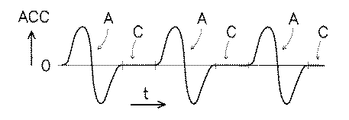
図2を参照して説明した制御ループの動作を図3aおよび図3bを参照してより詳細に説明する。図3aは、時間Tに対する可動部MPの加速度(acceleration)ACCの曲線を示す。図3aから、可動部は繰り返し、加速度が0の位相(phase)、たとえば、速度が一定または0の位相、および、可動部が加速および減速する位相にあることがわかる。このような加速、減速および一定速度または0速度というパターンは、たとえば、リソグラフィ装置のスキャンまたはステップ動作において起こりうる。このような場合において、基板(またはその一部)の照射は、速度が一定または0の位相において起こりうる。一方、加速または減速が起こる位相では、速度が一定または0である次の位相において、たとえば、基板の別の部分を照射するように、投影システム、または、基板テーブル、あるいは、あらゆるその他の適切な部分を移動させる。この例においては、可動部には、たとえば、基板テーブル(またはウェーハステージ)、投影システムの一部、他の部分の移動のバランスをとるカウンタバランスマス(counter balance mass)またはあらゆるその他適切な部分が含まれるとしてよい。また、可動部が、上記の例の構成要素、たとえば、ウェーハステージを駆動する作動装置、投影システムのプリズムまたはその他の光学素子等とすることも可能である。加速および減速が起こる位相中(図3aにおいてAで示されている)、セレクタは、第2制御部、従って第2コントローラ移動機能を選択し、これにより、制御ループの反応が迅速になりかつ整定時間が短くなり、よって、可動部が迅速に整定される。そして、加速度が0の位相中(この位相はCで示されている)、従って、一定速度または0速度の位相では、セレクタは、第1の制御部、従って、第1のコントローラ移動機能を選択し、最適な外乱除去を得る。したがって、コントローラ移動機能は、2つの位相のそれぞれにおいてその要件に合うように調整される。加速および減速が生じる位相では、制御ループの良好な動的性能をもたらすコントローラ移動機能が選択され、一方、速度が一定(0を含む)である位相では、高度な外乱除去が得られるコントローラ移動機能が選択される。 The operation of the control loop described with reference to FIG. 2 will be described in more detail with reference to FIGS. 3a and 3b. FIG. 3 a shows a curve of the acceleration ACC of the movable part MP with respect to time T. From FIG. 3a, it can be seen that the moving part is repeatedly in phase with zero acceleration, for example, a constant or zero phase, and a phase in which the moving part accelerates and decelerates. Such a pattern of acceleration, deceleration and constant or zero speed can occur, for example, in a scanning or stepping operation of the lithographic apparatus. In such cases, irradiation of the substrate (or part thereof) can occur at a constant or zero phase. On the other hand, in the phase where acceleration or deceleration occurs, in the next phase where the velocity is constant or zero, for example, the projection system or the substrate table or any other suitable so as to illuminate another part of the substrate Move part. In this example, the movable part includes, for example, a substrate table (or wafer stage), a part of the projection system, a counter balance mass or any other suitable part that balances movement of other parts. May be included. In addition, the movable part may be a component of the above example, for example, an actuator for driving the wafer stage, a prism of the projection system, or other optical elements. During the phase in which acceleration and deceleration occurs (indicated by A in FIG. 3a), the selector selects the second controller, and hence the second controller movement function, which makes the control loop react quickly and settles. Time is shortened, so that the movable part is settled quickly. And during the phase of zero acceleration (this phase is indicated by C), therefore, at constant speed or zero speed phase, the selector selects the first controller, and therefore the first controller movement function To obtain optimum disturbance rejection. Thus, the controller movement function is adjusted to meet its requirements in each of the two phases. In the phase where acceleration and deceleration occur, the controller movement function that provides good dynamic performance of the control loop is selected, while in the phase where the speed is constant (including 0), the controller movement function provides high disturbance rejection. Is selected.
別の例を図3bに示す。図3bでは、可動部の速度(velocity)Vが時間に対応して示されている。Vで示される位相において、可動部の速度は変化しており、Cで示される位相では、可動部の速度は一定(0及び非0値を含む)を有する。図3aと同様、可動部が非静止状態、すなわち、位相Vにおいては、第2のコントローラ移動機能がセレクタによって選択され、一方、可動部が実質的に静止状態、すなわち、本例においては、0速度を含め速度が一定である状態においては第1のコントローラ移動機能が選択される。図3aを参照して説明したものと同一または同様の効果がここでも得られる。 Another example is shown in FIG. In FIG. 3b, the velocity V of the movable part is shown as a function of time. In the phase indicated by V, the speed of the movable part changes, and in the phase indicated by C, the speed of the movable part is constant (including 0 and non-zero values). Similar to FIG. 3a, the second controller movement function is selected by the selector in the non-stationary state, i.e. phase V, while the movable part is substantially stationary, i.e. 0 in this example. In a state where the speed including the speed is constant, the first controller moving function is selected. The same or similar effect as described with reference to FIG.
図4は、第1および第2のコントローラ移動機能のゲイン(gain)Gを周波数(frequency)Fに対応して示す周波数ダイアグラム(frequency diagram)を示す。ゲインは、それぞれのコントローラ移動機能の大きさ(magnitude)を示すものであり、本例においては、第1のコントローラ移動機能についてI1、第2のコントローラ移動機能についてI2として図4に示す積分部分(integrative part)を含む。さらに、コントローラ移動機能は、第1のコントローラ移動機能についてP1、第2のコントローラ移動機能についてP2としてそれぞれ示される比例動作(proportional action)を含む。また、本例においては、コントローラ移動機能は、第1コントローラ移動機能についてD1、第2のコントローラ移動機能についてD2としてそれぞれ図4に示される微分動作(differential action)を含む。よって、第1のコントローラ移動機能および第2のコントローラ移動機能は、それぞれいわゆるPIDコントローラ移動機能を含む。図4に示されるとおり、第1および第2のコントローラ移動機能の比例部分(proportional part)および微分部分(differential part)は同じ値を有している。本例における第1のコントローラ移動機能と第2のコントローラ移動機能との違いは、第2のコントローラ移動機能の積分器ゲイン(integrator gain)I2が第1のコントローラ移動機能の積分器ゲインI1よりも高いことである。積分器ゲインI2が高いことにより、第2のコントローラ移動機能では、第1のコントローラ移動機能よりも良好な外乱除去(特に、低周波外乱(low frequency disturbance)の除去)が得られる。これに対して、第1のコントローラ移動機能では、積分器ゲインが低いため、第2のコントローラ移動機能によりも良好な整定時間が得られる。ゆえに、第1のコントローラ移動機能は、可動部が実質的に静止状態である場合に選択することができ、一方、第2のコントローラ移動機能は、可動部が実質的に非静止状態の場合に選択することができる。 FIG. 4 shows a frequency diagram showing the gain G of the first and second controller movement functions corresponding to the frequency F. The gain indicates the magnitude of each controller movement function. In this example, the integral part (shown in FIG. 4 as I1 for the first controller movement function and I2 for the second controller movement function). integrative part). Further, the controller movement function includes a proportional action indicated as P1 for the first controller movement function and P2 for the second controller movement function. Further, in this example, the controller movement function includes a differential action shown in FIG. 4 as D1 for the first controller movement function and D2 for the second controller movement function. Therefore, the first controller moving function and the second controller moving function each include a so-called PID controller moving function. As shown in FIG. 4, the proportional part and the differential part of the first and second controller movement functions have the same value. The difference between the first controller movement function and the second controller movement function in this example is that the integrator gain I2 of the second controller movement function is larger than the integrator gain I1 of the first controller movement function. It is expensive. Since the integrator gain I2 is high, the second controller movement function can provide better disturbance removal (particularly, low frequency disturbance removal) than the first controller movement function. On the other hand, in the first controller movement function, since the integrator gain is low, a better settling time can be obtained than in the second controller movement function. Thus, the first controller movement function can be selected when the movable part is substantially stationary, while the second controller movement function is selected when the movable part is substantially non-stationary. You can choose.
静止状態および非静止状態という用語は、あらゆる出力量を指すものであり、よって、静止状態とは、たとえば、一定温度、一定速度、一定加速度、一定照度、一定パルス繰り返し周波数、一定パルス電力等を指すものとできる。一方、非静止状態という用語は、上記に挙げた例が実質的に非一定である状態、すなわち、一定の変形、変動またはあらゆるその他の変化を示している状態を指すものとできる。 The terms stationary state and non-stationary state refer to all output quantities, and therefore, the stationary state refers to, for example, constant temperature, constant speed, constant acceleration, constant illuminance, constant pulse repetition frequency, constant pulse power, etc. It can be pointed to. On the other hand, the term non-stationary state may refer to a state in which the examples listed above are substantially non-constant, i.e., exhibiting a certain deformation, variation or any other change.
P1、I1およびD1を有する第1のコントローラ移動機能は、図2に示す第1の制御部C1に備えられ、P2、I2およびD2を有する第2のコントローラ移動機能は、図2に示す第2の制御部C2に備えられることができる。しかし、多くの代替が可能である。代替の一例を図5に示す。図2を参照して記載したときと同様に、図5は、可動部MPおよびセンサSENSを示す。また、設定点も同様に図2に示されており、センサの出力がこの設定点から差し引きされている。図5に示す例によると、コントローラは、微分ゲイン(differential gain)gD および微分器Dを備える微分経路(differential path)、比例ゲイン(proportional gain)gPを含む比例経路(proportional path)、積分器Iを含む積分経路(integrative path)、セレクタSEL、積分器ゲイン要素(integrator gain factor)gI1、gI2を備える。セレクタSELは、第1の積分器ゲイン要素gI1と第2の積分器ゲイン要素gI2との間で選択を行う。微分経路、比例経路および積分経路の出力は合計されてコントローラの出力信号となり、この出力信号は、可動部(より正確には、可動部を駆動するアクチュエータ)への入力として与えられる。よって、図2に示す第1の制御部と第2の制御部との間の選択の代わりに、図5のコントローラでは、第1と第2の制御部の異なる構成要素の中からのみ選択するセレクタが得られる。第1と第2のコントローラの比例および微分動作が同一であり、積分動作のみが異なるので、本例におけるセレクタは、異なる積分機能の中からのみ選択を行う。よって、第2のコントローラ移動機能を選択する場合、セレクタは、第2の積分ゲイン機能gI1を選択し、一方、第1のコントローラ移動機能が要求される場合、セレクタは、第1の積分器ゲイン要素gI1を選択する。図5に示す本実施形態の効果は、セレクタを切り換えるときに比較的円滑に移行(transition)が行われることである。差分動作および比例動作は、切り替えを必要としていないため、過渡電流(過渡信号 transients)またはその他の悪影響がここでは起こらないものと見込まれる。さらに、本例の積分動作では、ゲイン係数(gain factor)gI1またはgI2のみが選択されるが、これらは共に、同じ積分器Iを利用するものである。そのため、2つの積分器ゲイン係数gI1、gI2のうちのもう1つを選択した場合にも積分器Iの出力値は急な変化を示さない。その場合には、変化の瞬間に、積分器Iへの入力値のみが変化し、これにより積分器の出力において円滑な遷移、したがって、可動部の円滑な反応が行われるためである。よって、セレクタの切り換えによりコントローラCの出力値が段階的に変化するなどといった急な変化により起こりうる衝撃、段階的反応その他の現象を排除することができ、これにより第1のコントローラ移動機能と第2のコントローラ移動機能との間で円滑な移行が行われる。コントローラの入力信号を最初は微分器に、次に適切なセレクタに、そしてこれらを経た場合のみ、次に異なるゲイン要素へと導くことで、異なる微分動作との間で選択を行う場合に同様の効果を得ることができる。 The first controller moving function having P1, I1 and D1 is provided in the first controller C1 shown in FIG. 2, and the second controller moving function having P2, I2 and D2 is the second controller moving function shown in FIG. The control unit C2 can be provided. However, many alternatives are possible. An alternative example is shown in FIG. As when described with reference to FIG. 2, FIG. 5 shows the movable part MP and the sensor SENS. The set point is also shown in FIG. 2 and the sensor output is subtracted from this set point. According to the example shown in FIG. 5, the controller comprises a differential path comprising a differential gain gD and a differentiator D, a proportional path including a proportional gain gP, an integrator I Including an integral path, a selector SEL, and integrator gain factors gI1 and gI2. The selector SEL selects between the first integrator gain element gI1 and the second integrator gain element gI2. The outputs of the differential path, proportional path, and integration path are summed to become an output signal of the controller, and this output signal is given as an input to the movable part (more precisely, an actuator that drives the movable part). Therefore, instead of selecting between the first control unit and the second control unit shown in FIG. 2, the controller of FIG. 5 selects only from the different components of the first and second control units. A selector is obtained. Since the proportional and differential operations of the first and second controllers are the same and only the integration operation is different, the selector in this example selects only from different integration functions. Thus, when selecting the second controller movement function, the selector selects the second integral gain function gI1, while when the first controller movement function is required, the selector selects the first integrator gain. Element gI1 is selected. The effect of this embodiment shown in FIG. 5 is that transition is performed relatively smoothly when the selector is switched. Since differential and proportional operations do not require switching, transient currents or other adverse effects are not expected to occur here. Furthermore, in the integration operation of this example, only the gain factor gI1 or gI2 is selected, both of which utilize the same integrator I. Therefore, even when the other one of the two integrator gain coefficients gI1 and gI2 is selected, the output value of the integrator I does not show a sudden change. In that case, only the input value to the integrator I changes at the moment of change, and this causes a smooth transition in the output of the integrator, and thus a smooth reaction of the movable part. Therefore, it is possible to eliminate shocks, stepwise reactions and other phenomena that may occur due to a sudden change such as the output value of the controller C changing stepwise by switching the selector. A smooth transition between the two controller movement functions. The same is true when selecting between different differentiating operations by directing the controller's input signal first to the differentiator, then to the appropriate selector, and then only to the next different gain factor. An effect can be obtained.
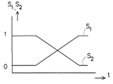
本発明のさらなる態様について図6を参照して説明する。本発明のさらなる態様によると、セレクタは、重み付きセレクタ(weighted selector)であってよい。重み付きセレクタは、重み係数(weighting coefficient)により第1の積分器ゲイン機能、第2の積分器ゲイン機能またはこれらの組み合わせのいずれかを選択する。図6は、時間Tに対するセレクタSELの重み係数を示している。まず、本例において、重み係数S1を0とし、重み係数S2を1とする。本例においては、重み係数S1は第1のコントローラ移動機能のものを示し、重み係数S2は、第2のコントローラ移動機能の重みづけを示す。まず、第2のコントローラ移動機能がセレクタにより選択される。しばらくしてから、第2の重み係数S2が低下すると同時に、第1の重み係数S1が上昇する。よって、その瞬間のセレクタの出力は、第1および第2のコントローラ移動機能の組み合わせとなる。徐々に、第1のコントローラ移動機能の重みづけが増加する一方、第2のコントローラ移動機能の重みづけが減少する。移行後は、第1の重み係数S1の値は1となり、第2の重み係数S2の値は0となるため、セレクタは、第1のコントローラ移動機能だけを選択する。図6の例では、段階的な移行(gradual transition)、すなわち、第1のコントローラ移動機能と第2のコントローラ移動機能との間の円滑な移行が得られる。これにより、第1のコントローラ移動機能と第2のコントローラ移動機能との間の切り換えの際に生じうる故障、工程またはその他の不要な作用を排除することができる。重み係数は、たとえば、重み関数係数発生器(weighting function coefficient generator)によって示され、たとえば、図6に示す係数値(S)を示す。重み関数係数発生器は、ハードウェアおよび/またはソフトウェアで実行することができる。 A further aspect of the present invention is described with reference to FIG. According to a further aspect of the invention, the selector may be a weighted selector. The weighted selector selects one of the first integrator gain function, the second integrator gain function, or a combination thereof according to the weighting coefficient. FIG. 6 shows the weighting factor of the selector SEL with respect to time T. First, in this example, the weighting factor S1 is set to 0, and the weighting factor S2 is set to 1. In this example, the weighting factor S1 indicates that of the first controller moving function, and the weighting factor S2 indicates the weighting of the second controller moving function. First, the second controller movement function is selected by the selector. After a while, the second weighting factor S2 decreases and at the same time the first weighting factor S1 increases. Therefore, the selector output at that moment is a combination of the first and second controller movement functions. Gradually, the weight of the first controller movement function increases while the weight of the second controller movement function decreases. After the transition, the value of the first weighting factor S1 is 1 and the value of the second weighting factor S2 is 0. Therefore, the selector selects only the first controller moving function. In the example of FIG. 6, a gradual transition, i.e. a smooth transition between the first controller movement function and the second controller movement function, is obtained. This eliminates failures, processes or other unwanted actions that can occur when switching between the first controller movement function and the second controller movement function. The weighting coefficient is indicated by, for example, a weighting function coefficient generator, and indicates, for example, the coefficient value (S) shown in FIG. The weight function coefficient generator can be implemented in hardware and / or software.
第1のコントローラ移動機能と第2のコントローラ移動機能との間の選択は、さまざまな方法で行ってよい。リソグラフィ装置の適切な制御装置(controlling device)、たとえば、その動作(の一部)を制御するものによってセレクタを駆動してもよい。制御装置は、たとえば、図2および図5等に示す制御ループの設定点の発生を制御する。一例として、制御装置が、たとえば、一定値を有する設定点を与える場合は、可動部の静止状態が得られ、よって、セレクタは、コントローラ移動機能のうちの適切な機能を1つ選択するよう駆動される。一方、制御デバイスが、変化する設定点、たとえば、時間によって変化する設定点を与えるよう設定点生成器を制御する場合、可動部の非静止状態が生じ得る。その場合、セレクタは、もう一つのコントローラ移動機能を選択するよう起動する。あるいは、セレクタは、設定信号によって駆動されてもよい。さらに、セレクタは、設定信号を受信する(図2に示す)設定点入力(setpoint input)S1を備えることができる。セレクタは、この設定信号から可動部の状態を決定し、これにより、設定信号に応じて適切なコントローラ移動機能を選択する。特に、セレクタは、設定信号が非静止状態である場合には第1のコントローラ移動機能を選択し、設定信号が静止状態である場合、好ましくは、少なくとも可動部の整定時間中に、第2のコントローラ移動機能を選択する。該整定時間中、移動(movement)の影響が落ち着く(settled)ことが考えられ、よって、少なくとも可動部の整定時間中に設定信号が静止状態にある場合にのみ第2のコントローラ移動機能を選択することによって、可動部の移動またはあらゆるその他非静止状態が落ち着き、可動部等の整定時間、すなわち、たとえば、設定信号が変化したときに落ち着くまでに必要な時間を考慮して、第1のコントローラ移動機能(非静止状態)から第2のコントローラ移動機能(静止状態)に変更するうえで最適な瞬間が得られる。 The selection between the first controller movement function and the second controller movement function may be made in various ways. The selector may be driven by a suitable controlling device of the lithographic apparatus, for example one that controls (part of) its operation. For example, the control device controls the generation of the set point of the control loop shown in FIGS. As an example, if the control device provides a set point having a constant value, for example, the stationary state of the movable part is obtained, so that the selector is driven to select one of the controller moving functions. Is done. On the other hand, if the control device controls the set point generator to provide a set point that changes, for example, a set point that changes with time, a non-stationary state of the movable part may occur. In that case, the selector is activated to select another controller movement function. Alternatively, the selector may be driven by a setting signal. Furthermore, the selector can comprise a setpoint input S1 (shown in FIG. 2) that receives a set signal. The selector determines the state of the movable part from the setting signal, and thereby selects an appropriate controller moving function according to the setting signal. In particular, the selector selects the first controller movement function when the setting signal is in a non-stationary state, and preferably when the setting signal is in a stationary state, preferably at least during the settling time of the movable part. Select the controller movement function. It is conceivable that the influence of movement settles during the settling time, so the second controller movement function is selected only when the set signal is stationary at least during the settling time of the movable part. The first controller moves in consideration of the movement of the movable part or any other non-stationary state, taking into account the settling time of the movable part, for example, the time required to settle when the setting signal changes. An optimal moment is obtained in changing from the function (non-stationary state) to the second controller movement function (stationary state).
本明細書では、IC製造におけるリソグラフィ装置の使用について具体的に言及しているが、本明細書記載のリソグラフィ装置が、集積光学システム、磁気ドメインメモリ用のガイダンスパターンおよび検出パターン、フラットパネルディスプレイ、液晶ディスプレイ(LCD)、薄膜磁気ヘッドといった他の用途を有することは、明らかである。当業者には当然のことであるが、そのような別の用途においては、本明細書で使われている用語「ウェーハ」または「ダイ」はすべて、それぞれより一般的な用語「基板」または「ターゲット部分」と同義であると考えればよい。本明細書に記載した基板は、露光の前後に、たとえば、トラック(通常、基板にレジスト層を塗布するツール)、メトロロジーツール、および/またはインスペクションツールで処理されてもよい。適用可能な場合には、本明細書中の開示物を上記のような基板プロセシングツールおよびその他の基板プロセシングツールに適用してもよい。さらに、基板は、たとえば、積層ICを作るために、複数回処理されてもよいので、本明細書で使われる用語基板が、すでに多重処理層を包含している基板を表すものとしてもよい。 Although this specification specifically refers to the use of a lithographic apparatus in IC manufacturing, the lithographic apparatus described herein includes integrated optical systems, guidance and detection patterns for magnetic domain memories, flat panel displays, Obviously, it has other uses such as liquid crystal displays (LCDs), thin film magnetic heads. As will be appreciated by those skilled in the art, in such other applications, the terms “wafer” or “die” as used herein are all generic terms “substrate” or “die”, respectively. It can be considered to be synonymous with “target portion”. The substrates described herein may be processed before and after exposure, for example, with a track (usually a tool for applying a resist layer to the substrate), metrology tools, and / or inspection tools. Where applicable, the disclosure herein may be applied to substrate processing tools such as those described above and other substrate processing tools. Further, since the substrate may be processed multiple times, for example, to make a stacked IC, the term substrate used herein may refer to a substrate that already contains multiple processing layers.
光学リソグラフィの分野での本発明の実施形態の使用について既に具体的に説明してきたが、言うまでもなく、本発明は、他の用途、たとえば、インプリントリソグラフィィに使われてもよく、さらに状況が許すのであれば、光学リソグラフィに限定されることはない。インプリントリソグラフィにおいては、パターン形成体内のトポグラフィによって基板上に創出されたパターンが定義される。パターン形成体のトポグラフィは、基板に供給されたレジスト層の中にプレス加工され、基板上では、電磁放射、熱、圧力、またはそれらの組合せによってレジストを硬化させることができる。パターン形成体は、レジストが硬化した後、レジスト内にパターンを残してレジストの外へ移動される。 Although the use of embodiments of the present invention in the field of optical lithography has been specifically described above, it will be appreciated that the present invention may be used in other applications, such as imprint lithography. If allowed, it is not limited to optical lithography. In imprint lithography, a pattern created on a substrate is defined by topography in a pattern forming body. The topography of the patterned body is pressed into a resist layer supplied to the substrate, whereupon the resist can be cured by electromagnetic radiation, heat, pressure, or a combination thereof. After the resist is cured, the pattern forming body is moved out of the resist leaving a pattern in the resist.
本明細書で使われている用語「放射線」および「ビーム」は、紫外線(UV)放射線(たとえば、約365、248、193、157、または126nmの波長を有する)、および極紫外線(EUV)放射線(たとえば、5〜20nmの範囲の波長を有する)、ならびにイオンビームや電子ビームなどの微粒子ビームを含むあらゆる種類の電磁放射線を包含している。 As used herein, the terms “radiation” and “beam” refer to ultraviolet (UV) radiation (eg, having a wavelength of about 365, 248, 193, 157, or 126 nm), and extreme ultraviolet (EUV) radiation. All types of electromagnetic radiation are included, including (eg, having a wavelength in the range of 5-20 nm), as well as particulate beams such as ion beams and electron beams.
用語「レンズ」は、状況が許すのであれば、屈折、反射、磁気、電磁気、および静電型光学部品を含むさまざまな種類の光学系のどれか1つまたは組合せを指すことができる。 The term “lens” can refer to any one or combination of various types of optical systems, including refractive, reflective, magnetic, electromagnetic, and electrostatic optics, if the situation allows.
以上、本発明の具体的で詳細な実施形態を説明してきたが、本発明は、説明された方法以外の別の方法で実行することが可能であることが明らかである。たとえば、本発明は、前述の方法を記載した機械読取可能命令の1つ以上のシーケンスを包含するコンピュータプログラムの形式、またはそのようなコンピュータプログラムを記録したデータストーレッジ媒体(たとえば、半導体メモリ、磁気または光学ディスク)を採用することもできる。 While specific and detailed embodiments of the invention have been described above, it will be appreciated that the invention may be practiced otherwise than as described. For example, the invention may be in the form of a computer program that includes one or more sequences of machine-readable instructions describing the method described above, or a data storage medium (eg, semiconductor memory, magnetic or An optical disk) can also be employed.
上記の説明は、制限ではなく例示を目的とし、したがって、当業者には明らかなように、添付の特許請求の範囲を逸脱することなく本記載の発明に変更を加えることもできる。 The above description is intended to be illustrative rather than restrictive, and, as will be apparent to those skilled in the art, modifications may be made to the invention described herein without departing from the scope of the appended claims.
Claims (24)
可動部の位置量を制御するコントローラであって、第1のコントローラ移動機能と第2のコントローラ移動機能を備え、かつ可動部の状態に応じて第1のコントローラ移動機能または第2のコントローラ移動機能を選択するセレクタをさらに備えるコントローラと、
を備えることを特徴とするリソグラフィ装置。 Moving parts;
A controller for controlling the position amount of the movable part, which has a first controller movement function and a second controller movement function, and the first controller movement function or the second controller movement function according to the state of the movable part A controller further comprising a selector for selecting
A lithographic apparatus comprising:
第1のコントローラ移動機能と第2のコントローラ移動機能とを設けることと、
可動部の状態に応じて第1のコントローラ移動機能または第2のコントローラ移動機能を選択することと、
を含む方法。 A method for controlling a positional amount of a movable part of a lithographic apparatus,
Providing a first controller moving function and a second controller moving function;
Selecting the first controller movement function or the second controller movement function according to the state of the movable part;
Including methods.
Applications Claiming Priority (1)
| Application Number | Priority Date | Filing Date | Title |
|---|---|---|---|
| US11/227,445 US7657334B2 (en) | 2005-09-16 | 2005-09-16 | Lithographic apparatus and control method |
Publications (1)
| Publication Number | Publication Date |
|---|---|
| JP2007110100A true JP2007110100A (en) | 2007-04-26 |
Family
ID=37885259
Family Applications (1)
| Application Number | Title | Priority Date | Filing Date |
|---|---|---|---|
| JP2006249159A Pending JP2007110100A (en) | 2005-09-16 | 2006-09-14 | Lithography device and control method |
Country Status (2)
| Country | Link |
|---|---|
| US (1) | US7657334B2 (en) |
| JP (1) | JP2007110100A (en) |
Cited By (1)
| Publication number | Priority date | Publication date | Assignee | Title |
|---|---|---|---|---|
| JP2009253287A (en) * | 2008-04-08 | 2009-10-29 | Asml Netherlands Bv | Stage system and lithographic apparatus equipped with the stage system |
Families Citing this family (2)
| Publication number | Priority date | Publication date | Assignee | Title |
|---|---|---|---|---|
| CN106774469B (en) * | 2008-06-11 | 2021-05-04 | 伊顿智能动力有限公司 | Automatic tuning electro-hydraulic valve |
| WO2014122223A1 (en) | 2013-02-08 | 2014-08-14 | Asml Netherlands B.V. | Lithographic apparatus and device manufacturing method |
Citations (5)
| Publication number | Priority date | Publication date | Assignee | Title |
|---|---|---|---|---|
| JPS6488810A (en) * | 1987-09-30 | 1989-04-03 | Nippon Seiko Kk | Method and device for positioning control using servo motor |
| JPH0511852A (en) * | 1991-07-02 | 1993-01-22 | Canon Inc | Positioning controller |
| JPH09258831A (en) * | 1996-03-22 | 1997-10-03 | Nissan Motor Co Ltd | Method and device for high-speed positioning |
| JPH10223522A (en) * | 1997-02-06 | 1998-08-21 | Nikon Corp | Aligner and aligning method |
| JP2000100721A (en) * | 1998-07-21 | 2000-04-07 | Nikon Corp | Scanning exposure method and scanning-type aligner and manufacture of apparatus |
Family Cites Families (7)
| Publication number | Priority date | Publication date | Assignee | Title |
|---|---|---|---|---|
| JP2866556B2 (en) * | 1993-09-02 | 1999-03-08 | 三菱電機株式会社 | Control device and control method for machine tool |
| EP1246014A1 (en) * | 2001-03-30 | 2002-10-02 | ASML Netherlands B.V. | Lithographic apparatus |
| TWI285299B (en) * | 2001-04-04 | 2007-08-11 | Asml Netherlands Bv | Lithographic manufacturing process, lithographic projection apparatus, and device manufactured thereby |
| US7209219B2 (en) * | 2003-03-06 | 2007-04-24 | Asml Netherlands B.V. | System for controlling a position of a mass |
| US7046093B1 (en) * | 2003-08-27 | 2006-05-16 | Intergrated Device Technology, Inc. | Dynamic phase-locked loop circuits and methods of operation thereof |
| TWI254190B (en) * | 2003-09-22 | 2006-05-01 | Asml Netherlands Bv | Lithographic apparatus, device manufacturing method, and device manufactured thereby |
| US7289858B2 (en) * | 2004-05-25 | 2007-10-30 | Asml Netherlands B.V. | Lithographic motion control system and method |
-
2005
- 2005-09-16 US US11/227,445 patent/US7657334B2/en active Active
-
2006
- 2006-09-14 JP JP2006249159A patent/JP2007110100A/en active Pending
Patent Citations (5)
| Publication number | Priority date | Publication date | Assignee | Title |
|---|---|---|---|---|
| JPS6488810A (en) * | 1987-09-30 | 1989-04-03 | Nippon Seiko Kk | Method and device for positioning control using servo motor |
| JPH0511852A (en) * | 1991-07-02 | 1993-01-22 | Canon Inc | Positioning controller |
| JPH09258831A (en) * | 1996-03-22 | 1997-10-03 | Nissan Motor Co Ltd | Method and device for high-speed positioning |
| JPH10223522A (en) * | 1997-02-06 | 1998-08-21 | Nikon Corp | Aligner and aligning method |
| JP2000100721A (en) * | 1998-07-21 | 2000-04-07 | Nikon Corp | Scanning exposure method and scanning-type aligner and manufacture of apparatus |
Cited By (2)
| Publication number | Priority date | Publication date | Assignee | Title |
|---|---|---|---|---|
| JP2009253287A (en) * | 2008-04-08 | 2009-10-29 | Asml Netherlands Bv | Stage system and lithographic apparatus equipped with the stage system |
| US8279407B2 (en) | 2008-04-08 | 2012-10-02 | Asml Netherlands B.V. | Stage system and lithographic apparatus comprising such stage system |
Also Published As
| Publication number | Publication date |
|---|---|
| US7657334B2 (en) | 2010-02-02 |
| US20070067057A1 (en) | 2007-03-22 |
Similar Documents
| Publication | Publication Date | Title |
|---|---|---|
| KR100937967B1 (en) | Lithographic apparatus and device manufacturing method | |
| JP4880665B2 (en) | Lithographic apparatus, stage system, and stage control method | |
| KR100696733B1 (en) | Lithographic apparatus and device manufacturing method | |
| JP2009194384A (en) | Movable support, position control system, lithographic apparatus, and method of controlling position of exchangeable object | |
| JP2008060563A (en) | Movable object position control method, positioning system, and lithographic equipment | |
| JP2007129218A (en) | Lithographic apparatus and device manufacturing method | |
| JP2006310849A (en) | Lithography equipment, position amount controller, and control method | |
| JP5705466B2 (en) | Method for controlling the position of a movable object, control system for controlling a positioning device, and lithographic apparatus | |
| JP2009130355A (en) | Lithographic apparatus and device manufacturing method | |
| JP2004342082A (en) | Control of position of mass especially in lithograph device | |
| US7016019B2 (en) | Lithographic apparatus and device manufacturing method | |
| JP4729065B2 (en) | Lithographic apparatus and method having a drive system with coordinate transformation | |
| JP2004343115A (en) | Control system, lithography system, process for fabricating device, and device fabricated through process | |
| JP5422633B2 (en) | Controller, lithographic apparatus, object position control method, and device manufacturing method | |
| JP5483480B2 (en) | Controller for positioning device, positioning device and lithographic apparatus comprising positioning device | |
| JP2007110100A (en) | Lithography device and control method | |
| JP4838834B2 (en) | Servo control system, lithography apparatus and control method | |
| JP4429296B2 (en) | Lithographic apparatus, projection apparatus and device manufacturing method | |
| US9977341B2 (en) | Lithographic apparatus and device manufacturing method | |
| JP2003068640A (en) | Lithographic projection apparatus, device manufacturing method, device manufactured thereby, and measurement method | |
| JP2005045227A (en) | Lithography apparatus and method for manufacturing device | |
| US7847919B2 (en) | Lithographic apparatus having feedthrough control system | |
| JP2020521156A (en) | Control system, method for increasing bandwidth of control system, and lithographic apparatus | |
| JP2010147467A (en) | Lithographic device and control method | |
| JP2005045246A (en) | Lithographic apparatus, device manufacturing method, and device manufactured thereby |
Legal Events
| Date | Code | Title | Description |
|---|---|---|---|
| A977 | Report on retrieval |
Free format text: JAPANESE INTERMEDIATE CODE: A971007 Effective date: 20090812 |
|
| A131 | Notification of reasons for refusal |
Free format text: JAPANESE INTERMEDIATE CODE: A131 Effective date: 20090814 |
|
| A521 | Written amendment |
Free format text: JAPANESE INTERMEDIATE CODE: A523 Effective date: 20091105 |
|
| A131 | Notification of reasons for refusal |
Free format text: JAPANESE INTERMEDIATE CODE: A131 Effective date: 20100506 |
|
| A521 | Written amendment |
Free format text: JAPANESE INTERMEDIATE CODE: A523 Effective date: 20100806 |
|
| A02 | Decision of refusal |
Free format text: JAPANESE INTERMEDIATE CODE: A02 Effective date: 20110107 |