JP2007107657A - Valve device - Google Patents
Valve device Download PDFInfo
- Publication number
- JP2007107657A JP2007107657A JP2005300673A JP2005300673A JP2007107657A JP 2007107657 A JP2007107657 A JP 2007107657A JP 2005300673 A JP2005300673 A JP 2005300673A JP 2005300673 A JP2005300673 A JP 2005300673A JP 2007107657 A JP2007107657 A JP 2007107657A
- Authority
- JP
- Japan
- Prior art keywords
- packing
- spring
- valve shaft
- hole
- spring case
- Prior art date
- Legal status (The legal status is an assumption and is not a legal conclusion. Google has not performed a legal analysis and makes no representation as to the accuracy of the status listed.)
- Granted
Links
Images


Classifications
-
- F—MECHANICAL ENGINEERING; LIGHTING; HEATING; WEAPONS; BLASTING
- F16—ENGINEERING ELEMENTS AND UNITS; GENERAL MEASURES FOR PRODUCING AND MAINTAINING EFFECTIVE FUNCTIONING OF MACHINES OR INSTALLATIONS; THERMAL INSULATION IN GENERAL
- F16K—VALVES; TAPS; COCKS; ACTUATING-FLOATS; DEVICES FOR VENTING OR AERATING
- F16K41/00—Spindle sealings
- F16K41/02—Spindle sealings with stuffing-box ; Sealing rings
- F16K41/04—Spindle sealings with stuffing-box ; Sealing rings with at least one ring of rubber or like material between spindle and housing
-
- F—MECHANICAL ENGINEERING; LIGHTING; HEATING; WEAPONS; BLASTING
- F16—ENGINEERING ELEMENTS AND UNITS; GENERAL MEASURES FOR PRODUCING AND MAINTAINING EFFECTIVE FUNCTIONING OF MACHINES OR INSTALLATIONS; THERMAL INSULATION IN GENERAL
- F16K—VALVES; TAPS; COCKS; ACTUATING-FLOATS; DEVICES FOR VENTING OR AERATING
- F16K41/00—Spindle sealings
- F16K41/02—Spindle sealings with stuffing-box ; Sealing rings
-
- F—MECHANICAL ENGINEERING; LIGHTING; HEATING; WEAPONS; BLASTING
- F16—ENGINEERING ELEMENTS AND UNITS; GENERAL MEASURES FOR PRODUCING AND MAINTAINING EFFECTIVE FUNCTIONING OF MACHINES OR INSTALLATIONS; THERMAL INSULATION IN GENERAL
- F16J—PISTONS; CYLINDERS; SEALINGS
- F16J15/00—Sealings
- F16J15/16—Sealings between relatively-moving surfaces
- F16J15/26—Sealings between relatively-moving surfaces with stuffing-boxes for rigid sealing rings
-
- F—MECHANICAL ENGINEERING; LIGHTING; HEATING; WEAPONS; BLASTING
- F16—ENGINEERING ELEMENTS AND UNITS; GENERAL MEASURES FOR PRODUCING AND MAINTAINING EFFECTIVE FUNCTIONING OF MACHINES OR INSTALLATIONS; THERMAL INSULATION IN GENERAL
- F16K—VALVES; TAPS; COCKS; ACTUATING-FLOATS; DEVICES FOR VENTING OR AERATING
- F16K31/00—Actuating devices; Operating means; Releasing devices
- F16K31/44—Mechanical actuating means
Landscapes
- Engineering & Computer Science (AREA)
- General Engineering & Computer Science (AREA)
- Mechanical Engineering (AREA)
- Details Of Valves (AREA)
- Sealing Devices (AREA)
Abstract
Description
この発明は、工場やプラント等において、配管に組み込まれる弁装置に関するものである。 The present invention relates to a valve device incorporated in piping in a factory or plant.
近年、大気汚染問題に関しては、特に揮発性有機物の排出規制が多く議論されている。米国と独国では、産業プラントの配管機器に対して、漏洩の定期検査と保全義務が法制化されており、今後、多くの国や地域が追随する見込みである。
規制に適合するには、グランドの封止性が長期間に渡って確保されることが要求される。これは当然、流体に関係なく設備の補修の周期を長くしたいという使用者の要求にも合致するものである。
そこで、パッキンメーカからは高封止性の新規パッキンが提供される一方、機器メーカからは、パッキン締め付け力の低下を補償するライブ・ロード構造(Live Load Packing System)を有する弁装置が提供されてきた。
In recent years, with regard to air pollution problems, there have been many discussions on emission regulations for volatile organic substances. In the United States and Germany, periodic inspections for leaks and maintenance obligations have been legislated for industrial plant piping equipment, and many countries and regions are expected to follow in the future.
In order to comply with the regulations, it is required that the sealing performance of the gland be ensured for a long period of time. Naturally, this also meets the user's requirement to lengthen the repair period regardless of the fluid.
Therefore, while a new highly sealable packing is provided from a packing manufacturer, a valve device having a live load structure (Live Load Packing System) that compensates for a decrease in packing tightening force has been provided from an equipment manufacturer. It was.
一般に、流体機器の封止部分に使用されるグランドパッキンは、その使用と共に締め付け力が低下し、シール性が弱まっていく。ライブ・ロード構造はこれをばねの復元力によって補償するものであり、従来より提案されてきたものである。 Generally, a gland packing used for a sealing portion of a fluid device has a tightening force that decreases with use of the gland packing, and a sealing property is weakened. The live load structure compensates for this by the restoring force of the spring, and has been proposed in the past.
ライブ・ロード構造を用いた弁装置の一例として、パッキンホロアとパッキンフランジの間に外部へ露呈する形で皿ばねを積層させた弁装置が提供されている(例えば、特許文献1参照)。図10は、特許文献1記載の弁装置を示す縦断面図である。
図10において、パッキンホロア3とパッキンフランジ9との間で皿ばね5が外部へ露呈しているので、皿ばね5の積層パターンを確認し易いという利点がある。ライブ・ロード機構の荷重特性は、皿ばね5の組み込み方向や枚数等により規定されるからである。
その一方で、皿ばね5の表面には塵埃等が付着する可能性がある。皿ばね5の積層部は空間が狭いことから、一度付着した塵埃は風雨でも洗い流されず、ステンレス製の皿ばねでも腐食される虞があった。
As an example of a valve device using a live load structure, a valve device is provided in which a disc spring is laminated between a packing follower and a packing flange so as to be exposed to the outside (see, for example, Patent Document 1). FIG. 10 is a longitudinal sectional view showing the valve device described in
In FIG. 10, since the
On the other hand, dust or the like may adhere to the surface of the
また、ライブ・ロード構造を用いた弁装置の別の一例として、皿ばねをパッキンホロアの中に収め、外部の塵埃から保護したライブ・ロード構造の弁装置が提供されている(例えば、特許文献2参照)。図11は、特許文献2記載の弁装置を示す縦断面図である。
図11において、パッキンホロア3に皿ばね5を収容しているので、外部の塵埃が付着し難い構造を有する。
しかしながら、特許文献2記載の弁装置においても、一度浸入した雨水は容易には排水されないので、ステンレス製の皿ばねでも腐食される虞があった。また、皿ばね5の積層パターンを外部から視認できないのは却って不都合を生じるという問題もあった。
As another example of a valve device using a live load structure, a valve device having a live load structure in which a disc spring is housed in a packing follower and protected from external dust is provided (for example, Patent Document 2). reference). FIG. 11 is a longitudinal sectional view showing the valve device described in
In FIG. 11, since the
However, even in the valve device described in
従来の弁装置は、以上のように構成されていたので、皿ばねの積層部に塵埃が付着し易いという課題があった。
また、皿ばねの積層部に塵埃が付着し難い構造とした場合には、皿ばね積層部に浸入した雨水が容易に排水されないという課題があった。
更に、上記の塵埃が付着し難い構造では、皿ばねの積層パターンを外部から視認できないという課題もあった。
Since the conventional valve device is configured as described above, there is a problem that dust easily adheres to the laminated portion of the disc springs.
Moreover, when it was set as the structure where a dust is hard to adhere to the laminated part of a disc spring, the subject that the rain water which permeated the disc spring laminated part was not drained easily occurred.
Furthermore, in the structure in which the dust is difficult to adhere, there is a problem that the laminated pattern of the disc springs cannot be visually recognized from the outside.
この発明は上記のような課題を解消するためになされたもので、外部から皿ばねの積層パターンを視認できると共に、皿ばねの積層部に塵埃が付着し難く、浸入した雨水が容易に排水される弁装置を提供することを目的とする。 The present invention has been made to solve the above-described problems. The disc spring laminated pattern can be visually recognized from the outside, dust is hardly attached to the disc spring laminated portion, and intruded rainwater is easily drained. It is an object of the present invention to provide a valve device.
この発明に係る弁装置は、パッキン収容手段内に上下動可能に挿入された弁軸と、前記パッキン収容手段と前記弁軸との間に介装されたグランドパッキンと、中央に設けられた弁軸通し穴と該弁軸通し穴の周囲に設けられた締結部材通し穴とを有し、前記グランドパッキンの上方にパッキン押さえ手段を介して配設されたパッキンフランジと、中央に弁軸通し穴を有するばね部材と、中央に設けられた弁軸通し穴と周壁に設けられた締結部材通し溝と窓部とを有し、該弁軸通し穴の下面開口部に少なくとも1つ以上の前記ばね部材を収納保持すると共に、前記弁軸通し穴の周囲の上面閉鎖部で前記パッキンフランジと当接するばねケースと、前記ばね部材と前記ばねケースと前記パッキンフランジとを介して前記グランドパッキンを押さえる複数の締結部材とを備えたことを特徴としたものである。 The valve device according to the present invention includes a valve shaft inserted into the packing housing means so as to be movable up and down, a gland packing interposed between the packing housing means and the valve shaft, and a valve provided in the center. A packing flange having a shaft through hole and a fastening member through hole provided around the valve shaft through hole, and disposed above the gland packing via packing pressing means; and a valve shaft through hole in the center A valve shaft through hole provided in the center, a fastening member through groove provided in the peripheral wall, and a window portion, and at least one or more of the springs in the lower surface opening of the valve shaft through hole The member is stored and held, and the gland packing is pressed through the spring case that contacts the packing flange at the upper surface closed portion around the valve shaft through hole, and the spring member, the spring case, and the packing flange. Is obtained is characterized in that a number of fastening members.
この発明に係る弁装置は、前記ばねケースの周壁に目盛が付されていることを特徴とするものである。 The valve device according to the present invention is characterized in that a scale is attached to a peripheral wall of the spring case.
この発明に係る弁装置は、前記ばねケースの周壁に設けられた前記締結部材通し溝と前記窓部とは同一形状の溝部であり、前記溝部は、前記ばねケースの周方向の配設位置に応じて前記締結部材通し溝または前記窓部となることを特徴としたものである。 In the valve device according to the present invention, the fastening member through-groove provided on the peripheral wall of the spring case and the window portion are groove portions having the same shape, and the groove portion is located at a circumferential position of the spring case. Accordingly, the fastening member through groove or the window portion is formed.
この発明に係る弁装置は、前記パッキンフランジと前記ばねケースとを一体フランジとしたことを特徴とするものである。 The valve device according to the present invention is characterized in that the packing flange and the spring case are formed as an integral flange.
この発明に係る弁装置は、前記ばねケースの下面開口部に脱落防止手段を備えることを特徴としたものである。 The valve device according to the present invention is characterized in that a drop-off preventing means is provided in the lower surface opening of the spring case.
この発明に係る弁装置は、パッキン収容手段内に上下動可能に挿入された弁軸と、前記パッキン収容手段と前記弁軸との間に介装されたグランドパッキンと、中央に弁軸通し穴を有するばね部材と、中央に設けられた弁軸通し穴と該弁軸通し穴の周囲に設けられた締結部材通し穴とを有し、前記弁軸通し穴の下面開口部に少なくとも1つ以上の前記ばね部材を収納保持すると共に、前記グランドパッキンの上方にパッキン押さえ手段を介して配設されるパッキンフランジと、前記ばね部材と前記パッキンフランジとを介して前記グランドパッキンを押さえる複数の締結部材とを備えたことを特徴としたものである。 The valve device according to the present invention includes a valve shaft inserted into the packing housing means so as to be movable up and down, a gland packing interposed between the packing housing means and the valve shaft, and a valve shaft through hole in the center. A spring member having a valve shaft through hole provided in the center and a fastening member through hole provided around the valve shaft through hole. At least one or more at the lower surface opening of the valve shaft through hole And a plurality of fastening members for holding the gland packing via the spring member and the packing flange. It is characterized by having.
この発明によれば、ばね部材がばねケースに覆われているので、ばね表面に塵埃が付着し難いという効果がある。
また、ばねケース周面の窓部から雨水が浸入した場合でも、下部に容易に排水されて滞留しないという効果がある。
更に、ばね部材の積層パターンを視認できるので、ライブ・ロード構造を弁装置に組み込む際にばね部材の組み込み方向や枚数が適切であるかどうかを容易に確認することができる。
According to the present invention, since the spring member is covered with the spring case, there is an effect that dust hardly adheres to the spring surface.
Further, even when rainwater enters from the window portion of the spring case peripheral surface, there is an effect that it is easily drained and does not stay in the lower part.
Further, since the lamination pattern of the spring members can be visually confirmed, it is possible to easily confirm whether or not the installation direction and the number of the spring members are appropriate when the live load structure is incorporated into the valve device.
この発明によれば、ばねケースの周壁に設けた目盛にばね部材の位置を合わせることにより、容易にばね部材の圧縮量を調節することができる。 According to this invention, the amount of compression of the spring member can be easily adjusted by aligning the position of the spring member with the scale provided on the peripheral wall of the spring case.
この発明によれば、ライブ・ロード機構を弁装置に組み付ける際に、締結部材通し溝か窓部かを区別する必要がなく、組み付け時の作業効率を向上することができる。 According to the present invention, when assembling the live load mechanism to the valve device, it is not necessary to distinguish between the fastening member through groove and the window portion, and the working efficiency at the time of assembly can be improved.
この発明によれば、ばねケースとパッキンフランジとを一体化することにより、基本機能は変えずに部品点数を削減し、組み付け性の向上やコスト低減を図ることができる。 According to this invention, by integrating the spring case and the packing flange, it is possible to reduce the number of parts without changing the basic function, and to improve the assembling property and the cost.
この発明によれば、脱落防止手段を設けることにより、ばねケースに収容したばね部材の脱落を防止することで、ライブ・ロード機構の弁装置への組み付け時の作業効率を向上することができる。 According to the present invention, by providing the drop prevention means, it is possible to improve the working efficiency when the live load mechanism is assembled to the valve device by preventing the spring member housed in the spring case from falling off.
この発明によれば、ばね部材をパッキンフランジ内に収納するので組み付け性が向上すると共に、雨水の浸入や塵埃の付着を防止することができる。 According to this invention, since the spring member is housed in the packing flange, the assemblability can be improved, and intrusion of rainwater and adhesion of dust can be prevented.
実施の形態1.
以下、この発明の実施の形態1について説明する。図1は、この発明の実施の形態1に係る弁装置を示す縦断面図である。
図1において、スタッフィンボックス1(パッキン収容手段)内に、弁軸4が上下動可能に挿入されている。グランドパッキン2は、スタッフィンボックス1と弁軸4との間に介装されている。更に、グランドパッキン2の上面には弁軸4を挿通したパッキンホロア3が当接されている。
皿ばね5(ばね部材)は積層する状態で、ばねケース6の下面開口部から収納される。そして、皿ばね5とばねケース6のそれぞれの中央の穴(以下、弁軸通し穴)に弁軸4を挿通し、パッキンフランジ9とパッキンホロア3(パッキン押さえ手段)との間に配設される。
パッキンフランジ9は、ばねケース6の弁軸通し穴の周囲の上面閉鎖部に当接し、グランドパッキン2の上方にパッキンホロア3を介して配設されている。
スタッドボルト7(締結部材)は、パッキンフランジ9の外周部近傍、弁軸通し穴の周囲に設けられた貫通穴(以下、締結部材通し穴)を介して、スタッフィンボックス1の上部のねじ穴に螺合される。スタッドボルト7の上端ねじ部にはナット8(締結部材)が螺合される。その際に、スタッドボルト7が、ばねケース6の外周部に設けられた溝部12を通るように配置される。
In FIG. 1, a valve shaft 4 is inserted into a stuffing box 1 (packing accommodating means) so as to be movable up and down. The
The disc spring 5 (spring member) is housed from the lower surface opening of the
The
The stud bolt 7 (fastening member) is a screw hole in the upper portion of the
次に、図1の弁装置の組み立て手順について説明する。上記のような構造を組み立てる場合、下記の手順(1)〜(5)の順番で行う。
(1) 弁軸4にグランドパッキン2、パッキンホロア3を通す。
(2) スタッドボルト7の先端ねじ部をスタッフィンボックス1の上部ねじ穴に螺合する。
(3) ばねケース6に皿ばね5を収容して、弁軸4とスタッドボルト7に通す。
(4) ばねケース6の上から、パッキンフランジ9の弁軸通し穴に弁軸4を、締結部材通し穴にスタッドボルト7を通す。
(5) ナット8をスタッドボルト7の上端ねじ部に螺合させて、パッキンフランジ9の上から締め付ける。
なお、手順(1)〜(3)までについては順番の入れ替えが可能である。
Next, the assembly procedure of the valve device of FIG. 1 will be described. When assembling the structure as described above, the following procedures (1) to (5) are performed.
(1) Pass the gland packing 2 and the
(2) The tip screw portion of the
(3) The
(4) Pass the valve shaft 4 through the valve shaft through hole of the packing
(5) The
Note that the order of the procedures (1) to (3) can be changed.
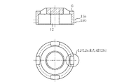
図2は、図1中のばねケースを示す図であり、上段は縦断面図、下段は上面図である。図2において、ばねケース6は、周壁に同幅、同形状の溝部12を90°間隔で4つ設けている。溝部12は、対向する1組は、スタッドボルト7を通す締結部材通し溝12aとなる。また、他の対向する1組は、スタッドボルト7を通さず、内部の皿ばね6の状態を視認するための窓部12bとなる。
ばねケース6の周壁表面で溝部12上方には、初期組み込み時と最終締め付け時に、内部の皿ばね5の位置を確認する糸溝15a(締め付け時目盛)、15b(組み付け時目盛)を設けている。ナット8を締め込んでいくと皿ばね5は圧縮されて初期位置より上昇するので、初期組み込み時の目盛が糸溝15b(組み付け時目盛)となり、最終締め付け時の目盛が糸溝15a(締め付け時目盛)となる。
また、ばねケース6は、外部の塵埃や雨水等から、弁軸4と皿ばね5を保護する機能も有する。
FIG. 2 is a view showing the spring case in FIG. 1, wherein the upper stage is a longitudinal sectional view and the lower stage is a top view. In FIG. 2, the
On the peripheral wall surface of the
The
図3は、図1中のばねケースへ皿ばねを積層する場合の組み立て図である。図3において、皿ばね5は、中空の円錐台状であり、4枚の皿ばね5の上面と下面とを互い違いに当接して、ばねケース6の下面開口部側から収容される。その際、皿ばね5はばねケース6の内周面で位置決めされ、皿ばね5とばねケース6の軸中心は一致する。
更に、皿ばね5とばねケース6とを弁装置へ組み付ける際には、ばねケース6は外周部の締結部材通し溝12aでスタッドボルト7にガイドされるので、両者の軸中心は弁軸4と一致する。
FIG. 3 is an assembly diagram when a disc spring is stacked on the spring case in FIG. 1. In FIG. 3, the
Further, when the
図4は、図1の弁装置にばねケースを組み付け後、窓部方向から見た場合の正面図である。図4において、窓部12bを正面から見ることにより、組み付け時には皿ばね5の位置を糸溝15b(組み付け時目盛)と合わせ、締め付け時には皿ばね5の位置が糸溝15a(締め付け時目盛)に合致するまでナット8を締める。締め付け時目盛は、皿ばね圧縮量の指示目盛であり、この線に皿ばね5を合わせるだけで、ナット8の締め付けトルクの管理等が不要となり、位置決めが容易である。
FIG. 4 is a front view when the spring device is assembled to the valve device of FIG. 1 and viewed from the window direction. In FIG. 4, when the
次に、ナット8締め付け時の状態について説明する。ナット8を締め込んでいくと、ばねケース6は、ナット8によるパッキンフランジ9への締め付け力を受ける。
パッキンホロア3へは、皿ばね5の初期圧縮からの復元力が作用している。皿ばね5は全てスタッフィンボックス1の外部にあるため、仮に雨水が浸入した場合でも容易に排水され、皿ばね5の積層部に溜まることはない。
皿ばね5は、ばねケース6により外径がガイドされながら圧縮荷重を受ける。ばねケース6は、外部の塵埃から弁軸4及び皿ばね5を保護する機能も有する。
ばねケース6は軸中心が弁軸4と一致するようにスタッドボルト7によりガイドされる。そのため、弁軸4と皿ばね5とが接触することはない。
スタッフィンボックス1の最下に詰められるグランドパッキン2は、パッキンホロア3より圧縮荷重を受け、スタッフィングボックス1と弁軸4とを締め付け、流体を封止する。
Next, a state when the
A restoring force from the initial compression of the
The
The
The gland packing 2 packed at the bottom of the
以上の説明で用いた皿ばね5の代わりに、外形が楕円や多角形状等で弁軸4を挿通する弁軸通し穴を有する板ばね等を用いてもよい。その際には、ばねケース6も、上記板ばねを収容可能な形状(内部形状や外部形状)とする必要がある。
Instead of the
以上のように、この実施の形態1によれば、皿ばね5がばねケース6に覆われているので、皿ばね5表面に塵埃が付着し難いという効果が得られる。
ばねケース6周面の窓部12bから雨水が浸入した場合でも、下部に容易に排水され、滞留しないという効果が得られる。
皿ばね5の積層パターンが外部から見ることができるので、ライブ・ロード構造を弁装置に組み込む際に、その荷重特性を支配する皿ばね5の組み込み方向や枚数が、適切であるかどうかを確認し易いという効果がある。
ばねケース6の周壁に目盛が付されているので、皿ばね5の圧縮量が適切かどうかも確認し易いという効果がある。
また、締結部材通し溝12aと窓部12bとを共通の構造を有する溝部12とすることで、ライブ・ロード機構を弁装置に組み付ける際のばねケース6の周方向の配設位置に応じて、溝部12を締結部材通し溝12aまたは窓部12bとすることができる。
As described above, according to the first embodiment, since the
Even when rainwater enters from the
Since the laminating pattern of the disc springs 5 can be seen from the outside, when the live load structure is incorporated into the valve device, it is confirmed whether the disc springs 5 that dominate the load characteristics are appropriate in the direction and number of disc springs. There is an effect that it is easy to do.
Since the scale is attached to the peripheral wall of the
Further, by using the fastening member through
実施の形態2.
以下、この発明の実施の形態2について説明する。図5は、この発明の実施の形態2に係る弁装置を示す縦断面図である。図5の弁装置は、図1中のばねケース6とパッキンフランジ9の代わりに、両者を一体化した一体フランジ10(パッキンフランジ)を備えている。一体フランジ10では、軸中心が1つであり、弁軸4と一致させることも容易である。その他の構成は、実施の形態1と同様であるので説明を省略する。
The second embodiment of the present invention will be described below. FIG. 5 is a longitudinal sectional view showing a valve device according to
以上のように、この実施の形態2によれば、ばねケース6とパッキンフランジ9とを一体化することにより、基本機能は変えずに部品点数を削減し、組み付け性の向上やコスト低減を図ることができる。
As described above, according to the second embodiment, the
実施の形態3.
以下、この発明の実施の形態3について説明する。図6は、この発明の実施の形態3に係る弁装置に組み付けるばねケースを示す図であり、上段は縦断面図、下段は上面図である。図6において、ばねケース6の下部に、軸方向に向かって突出する脱落防止片13(脱落防止手段)を取り付けている。脱落防止片13は、ばねケース6に収容した皿ばね5の脱落を防止する機能を有する。その他の構成は、実施の形態1と同様であるので説明を省略する。
また、図7は、図6と異なるばねケースを示す図であり、上段は縦断面図、下段は上面図である。図7では、図6で示した脱落防止片13の代わりに、ばねケース6の外周部下面に円環状の脱落防止蓋14(脱落防止手段)を取り付けたものである。脱落防止蓋14において、溝部12と当接する部分は、溝部12の断面形状と略同様の凹形であり、スタッドボルト7が配設される。脱落防止蓋14の機能も脱落防止片13と同様である。
FIG. 7 is a view showing a spring case different from FIG. 6, wherein the upper stage is a longitudinal sectional view and the lower stage is a top view. In FIG. 7, instead of the drop-
以上のように、この実施の形態3によれば、脱落防止手段を設けることにより、ばねケース6に収容した皿ばね5の脱落防止することで、ばねケース6の弁装置への組み付け性の向上を図ることができる。
As described above, according to the third embodiment, by providing the drop prevention means, the
実施の形態4.
以下、この発明の実施の形態4について説明する。図8は、この発明の実施の形態4に係る弁装置に組み付けるばねケースを示す図であり、上段は正面図、下段は上面図である。図8において、ばねケース6の外周部に合計6個の溝部12を設けている。このうち、正三角形の頂点を成す1組の溝部12がスタッドボルト7を通す締結部材通し溝12aとなり、残り1組の正三角形の頂点を成す溝部12が窓部12bとなる。即ち、ばねケース6は3本のスタッドボルト7でガイドされる。また、図示しないが、スタッフィンボックス1とパッキンフランジ9にも対応する3箇所のねじ部及び締結部材通し穴が設けられている。
Embodiment 4 FIG.
The fourth embodiment of the present invention will be described below. FIG. 8 is a view showing a spring case assembled to a valve device according to Embodiment 4 of the present invention, in which the upper part is a front view and the lower part is a top view. In FIG. 8, a total of six
また、実施の形態1ではスタッドボルトが2本の場合、実施の形態4では3本の場合について説明したが、ばねケース6の外周部(周壁)に設ける溝部12の数を、使用するスタッドボルトの本数の整数倍設け、なおかつ隣接する溝部12同士の間隔をばねケース6の周方向で等分(等角度)とすればよい。これにより、種々の設計変更に対応することができる。
なお、溝部12の数をスタッドボルト7の本数に比例させない場合や、溝部12の配置を敢えて等間隔としない場合も考えられるが、加工性の観点からは上記の方法が望ましい。また、溝部12の数は、加工性や、皿ばね5の暴露部分を極力少なくする観点から、スタッドボルト7の本数の2倍程度が好ましい。
Further, in the first embodiment, the case where there are two stud bolts and the case where there are three stud bolts in the fourth embodiment has been described. However, the number of the
In addition, although the case where the number of the
以上のように、この実施の形態4によれば、スタッドボルト7の本数を整数倍した数の溝部12を設け、それらの配置を周方向等分とすることにより、締結部材通し溝12aに通したスタッドボルト7によるばねケース6の軸中心の位置決めと、窓部12bとを必ず同時に実現することができる。
As described above, according to the fourth embodiment, the number of the
実施の形態5.
以下、この発明の実施の形態5について説明する。図9は、この発明の実施の形態5に係る弁装置を示す縦断面図である。図9の弁装置は、実施の形態2(図5)で示した一体フランジ11の代わりに、溝部12を廃した一体フランジ11(パッキンフランジ)を備えている。一体フランジ11において、スタッドボルト7は、皿ばね5を収容するばね部材収容部16よりも外側に配設される。それに伴い、スタッフィンボックス1においてねじ穴と軸中心を結ぶ径も大きくなる。
The fifth embodiment of the present invention will be described below. FIG. 9 is a longitudinal sectional view showing a valve device according to
この構成により、一体フランジ11の外周部に窓部は設けられないものの、一体フランジ11内部に収容される皿ばね5が外部に暴露される部分がなくなり、雨水の浸入や塵埃の付着を一層防止することができる。
なお、ばね部材収容部16の周壁に実施の形態1〜4で示した溝部12を設け、スタッドボルト7を配設するようにしてもよい。この場合には、溝部12の数とスタッドボルト7の本数が同一となる。
With this configuration, although no window portion is provided on the outer peripheral portion of the
In addition, the
以上のように、この実施の形態5によれば、窓部の機能はないものの、部品点数を削減し、組み付け性の向上やコスト低減を図ることができる。
また、窓部を設けないことにより、雨水の浸入や塵埃の付着防止効果をより高めることができる。
As described above, according to the fifth embodiment, although there is no function of the window portion, it is possible to reduce the number of parts and improve the assembling property and the cost.
Further, by not providing the window portion, it is possible to further enhance the effect of preventing rainwater from entering and dust from adhering.
なお、以上の説明において、便宜上、上下左右等の表現を用いたが、実際の弁装置の設置方向は様々であり、以上の説明で用いた方向に限定されるものではない。 In the above description, for the sake of convenience, expressions such as up, down, left and right are used. However, the actual installation direction of the valve device is various, and is not limited to the direction used in the above description.
1 スタッフィンボックス
2 グランドパッキン
3 パッキンホロア
4 弁軸
5 皿ばね
6 ばねケース
7 スタッドボルト
8 ナット
9 パッキンフランジ
10 一体フランジ(溝あり)
11 一体フランジ(溝なし)
12 溝部
12a 締結部材通し溝
12b 窓部
13 脱落防止片
14 脱落防止蓋
15a 糸溝(締め付け時目盛)
15b 糸溝(組み付け時目盛)
16 ばね部材収容部
1
11 Integrated flange (no groove)
12
15b Thread groove (Scale when assembled)
16 Spring member housing
Claims (6)
前記パッキン収容手段と前記弁軸との間に介装されたグランドパッキンと、
中央に設けられた弁軸通し穴と該弁軸通し穴の周囲に設けられた締結部材通し穴とを有し、前記グランドパッキンの上方にパッキン押さえ手段を介して配設されたパッキンフランジと、
中央に弁軸通し穴を有するばね部材と、
中央に設けられた弁軸通し穴と周壁に設けられた締結部材通し溝と窓部とを有し、該弁軸通し穴の下面開口部に少なくとも1つ以上の前記ばね部材を収納保持すると共に、前記弁軸通し穴の周囲の上面閉鎖部で前記パッキンフランジと当接するばねケースと、
前記ばね部材と前記ばねケースと前記パッキンフランジとを介して前記グランドパッキンを押さえる複数の締結部材とを備えたことを特徴とする弁装置。 A valve shaft inserted into the packing housing means so as to be movable up and down;
A gland packing interposed between the packing housing means and the valve shaft;
A packing flange that has a valve shaft through hole provided in the center and a fastening member through hole provided around the valve shaft through hole, and is disposed above the gland packing via packing holding means;
A spring member having a valve shaft through hole in the center;
A valve shaft through hole provided in the center, a fastening member through groove provided in the peripheral wall, and a window portion; and at least one spring member is housed and held in a lower surface opening of the valve shaft through hole. A spring case that abuts against the packing flange at an upper surface closing portion around the valve shaft through hole;
A valve device comprising: a plurality of fastening members for holding the gland packing through the spring member, the spring case, and the packing flange.
前記溝部は、前記ばねケースの周方向の配設位置に応じて前記締結部材通し溝または前記窓部となることを特徴とする請求項1記載の弁装置。 The fastening member through groove provided on the peripheral wall of the spring case and the window portion are groove portions having the same shape,
The valve device according to claim 1, wherein the groove portion serves as the fastening member through groove or the window portion in accordance with a circumferential arrangement position of the spring case.
前記パッキン収容手段と前記弁軸との間に介装されたグランドパッキンと、
中央に弁軸通し穴を有するばね部材と、
中央に設けられた弁軸通し穴と該弁軸通し穴の周囲に設けられた締結部材通し穴とを有し、前記弁軸通し穴の下面開口部に少なくとも1つ以上の前記ばね部材を収納保持すると共に、前記グランドパッキンの上方にパッキン押さえ手段を介して配設されるパッキンフランジと、
前記ばね部材と前記パッキンフランジとを介して前記グランドパッキンを押さえる複数の締結部材とを備えたことを特徴とする弁装置。 A valve shaft inserted into the packing housing means so as to be movable up and down;
A gland packing interposed between the packing housing means and the valve shaft;
A spring member having a valve shaft through hole in the center;
It has a valve shaft through hole provided in the center and a fastening member through hole provided around the valve shaft through hole, and at least one spring member is accommodated in the lower surface opening of the valve shaft through hole. And holding a packing flange disposed above the gland packing via packing pressing means;
A valve device comprising a plurality of fastening members for holding the gland packing through the spring member and the packing flange.
Priority Applications (5)
| Application Number | Priority Date | Filing Date | Title |
|---|---|---|---|
| JP2005300673A JP4721863B2 (en) | 2005-10-14 | 2005-10-14 | Valve device |
| TW095134422A TWI310444B (en) | 2005-10-14 | 2006-09-18 | Valve device |
| US11/543,910 US7753339B2 (en) | 2005-10-14 | 2006-10-06 | Valve device |
| KR1020060099715A KR100822069B1 (en) | 2005-10-14 | 2006-10-13 | Valve device |
| CNB2006101361430A CN100447468C (en) | 2005-10-14 | 2006-10-13 | Valve device |
Applications Claiming Priority (1)
| Application Number | Priority Date | Filing Date | Title |
|---|---|---|---|
| JP2005300673A JP4721863B2 (en) | 2005-10-14 | 2005-10-14 | Valve device |
Publications (2)
| Publication Number | Publication Date |
|---|---|
| JP2007107657A true JP2007107657A (en) | 2007-04-26 |
| JP4721863B2 JP4721863B2 (en) | 2011-07-13 |
Family
ID=38018394
Family Applications (1)
| Application Number | Title | Priority Date | Filing Date |
|---|---|---|---|
| JP2005300673A Active JP4721863B2 (en) | 2005-10-14 | 2005-10-14 | Valve device |
Country Status (5)
| Country | Link |
|---|---|
| US (1) | US7753339B2 (en) |
| JP (1) | JP4721863B2 (en) |
| KR (1) | KR100822069B1 (en) |
| CN (1) | CN100447468C (en) |
| TW (1) | TWI310444B (en) |
Cited By (3)
| Publication number | Priority date | Publication date | Assignee | Title |
|---|---|---|---|---|
| KR101803343B1 (en) | 2016-05-27 | 2017-12-01 | 주식회사 대정밸브 | Micro control valve and a method of manufacturing the same |
| US10234035B2 (en) | 2016-10-31 | 2019-03-19 | Azbil Corporation | Seal structure of regulating valve gland portion |
| JP2023504776A (en) * | 2019-12-31 | 2023-02-07 | 浙江大学 | VALVE SEALING STRUCTURE AND METHOD FOR WEAR REDUCTION |
Families Citing this family (19)
| Publication number | Priority date | Publication date | Assignee | Title |
|---|---|---|---|---|
| KR100819417B1 (en) * | 2007-11-09 | 2008-04-04 | 한국키스톤발부(주) | Valve provided with a pressing flange |
| US8551809B2 (en) * | 2008-05-01 | 2013-10-08 | Intermolecular, Inc. | Reduction of forming voltage in semiconductor devices |
| US8062918B2 (en) * | 2008-05-01 | 2011-11-22 | Intermolecular, Inc. | Surface treatment to improve resistive-switching characteristics |
| US8053364B2 (en) * | 2008-05-01 | 2011-11-08 | Intermolecular, Inc. | Closed-loop sputtering controlled to enhance electrical characteristics in deposited layer |
| US7968452B2 (en) * | 2009-06-30 | 2011-06-28 | Intermolecular, Inc. | Titanium-based high-K dielectric films |
| US8632053B2 (en) * | 2010-05-11 | 2014-01-21 | Fisher Controls International, Llc | Movable valve apparatus having conditioned lubricating surfaces |
| US20120301061A1 (en) * | 2011-05-26 | 2012-11-29 | Ward Forrest | Sootblower stuffing box and seal |
| US8814432B2 (en) | 2012-03-23 | 2014-08-26 | Seal-Ryt Corporation | Seal-bearing assembly |
| US9347488B2 (en) | 2012-03-23 | 2016-05-24 | Seal-Ryt Corporation | Seal-bearing assembly |
| ES2553231T3 (en) | 2012-12-27 | 2015-12-07 | Nuovo Pignone S.R.L. | Manufacture of packing cups |
| US8939646B2 (en) | 2013-04-12 | 2015-01-27 | Ward Forrest | Shaft support and lubrication assembly |
| TWI601894B (en) * | 2013-10-18 | 2017-10-11 | 進典工業股份有限公司 | Stuffing box seal ring with toughness |
| CN103884579B (en) * | 2014-03-14 | 2016-08-17 | 中信戴卡宁波轮毂制造有限公司 | Spring rate detection device |
| DE102014015892A1 (en) * | 2014-10-27 | 2016-04-28 | Samson Ag | Stellarmatur comprising a sealing arrangement |
| EP3274614B1 (en) * | 2015-03-23 | 2020-05-20 | Atomic Energy of Canada Limited/ Énergie Atomique du Canada Limitée | Valve packing assembly having shape-memory member |
| CN106246919A (en) * | 2016-10-09 | 2016-12-21 | 中国核动力研究设计院 | One prevents pretightning force from relaxing and easily detachable packing seal structure |
| US10443742B2 (en) * | 2017-11-01 | 2019-10-15 | Fisher Control International Llc | Packing apparatus and related methods to identify proper loading for valve packing |
| CN110219995A (en) * | 2019-07-11 | 2019-09-10 | 沅亨流体科技(昆山)有限公司 | A kind of high leakproofness high pressure needle valve |
| US11143314B1 (en) * | 2020-03-25 | 2021-10-12 | Fisher Controls International Llc | Methods and apparatus to load a valve packing |
Citations (10)
| Publication number | Priority date | Publication date | Assignee | Title |
|---|---|---|---|---|
| US3113755A (en) * | 1962-07-05 | 1963-12-10 | Don J Stevens | Vibration damping and shock mount |
| JPS61171970A (en) * | 1984-09-26 | 1986-08-02 | シュラムバーガー アンデュストリエ | Ball type valve with removable valve seat which can be maintained rapidly |
| JPS6430973A (en) * | 1987-07-08 | 1989-02-01 | Fisher Controls Int | Spring load packing |
| US5024453A (en) * | 1988-12-20 | 1991-06-18 | Pressure Services, Inc. | Liveload assembly for rotary or reciprocating shaft packing |
| US5056757A (en) * | 1990-10-12 | 1991-10-15 | Fisher Controls International, Inc. | Packing containment for live loaded fugitive emission seals |
| US5190264A (en) * | 1992-03-03 | 1993-03-02 | Dresser Industries, Inc. | Adjustable valve packing arrangement |
| US5290010A (en) * | 1992-06-12 | 1994-03-01 | Cashco, Inc. | Multiple thrust range live loade packing system for stems, shafts, etc. |
| US5316319A (en) * | 1992-09-22 | 1994-05-31 | Rm Engineered Products, Inc. | Liveload assembly for maintaining torque on bolts |
| US5503406A (en) * | 1993-11-26 | 1996-04-02 | Neles-Jamesbury | Assembly for live loading or valve packings |
| JPH11166628A (en) * | 1997-12-04 | 1999-06-22 | Yamatake Corp | Valve device and adjusting method therefor |
Family Cites Families (11)
| Publication number | Priority date | Publication date | Assignee | Title |
|---|---|---|---|---|
| US3087735A (en) * | 1961-09-13 | 1963-04-30 | Fisher Governor Co | Packing box constructions |
| JPS6430973U (en) | 1987-08-18 | 1989-02-27 | ||
| CN88212234U (en) | 1988-03-04 | 1988-11-23 | 奚长寿 | Adjustable temp. and pressure valve for pressure cooker |
| US5129625A (en) * | 1990-10-09 | 1992-07-14 | Fisher Controls International, Inc. | Live load packing system |
| JPH0681992B2 (en) * | 1990-10-09 | 1994-10-19 | 岡野バルブ製造株式式会社 | Valve device |
| US5090087A (en) * | 1991-04-12 | 1992-02-25 | The Babcock & Wilcox Company | Hub assembly for sootblower |
| JP2595005Y2 (en) * | 1991-10-21 | 1999-05-24 | 日本ピラー工業株式会社 | Gland packing stress relaxation compensator |
| JPH08233154A (en) * | 1995-02-24 | 1996-09-10 | Kansai Electric Power Co Inc:The | Non-leakage valve |
| US5549305A (en) * | 1995-04-07 | 1996-08-27 | Freund; Melvin A. | Sootblower packing gland |
| JP3450165B2 (en) | 1997-10-22 | 2003-09-22 | 株式会社山武 | Valve device |
| CN2480112Y (en) | 2001-06-01 | 2002-03-06 | 李兴刚 | Novel screwdriver |
-
2005
- 2005-10-14 JP JP2005300673A patent/JP4721863B2/en active Active
-
2006
- 2006-09-18 TW TW095134422A patent/TWI310444B/en active
- 2006-10-06 US US11/543,910 patent/US7753339B2/en active Active
- 2006-10-13 KR KR1020060099715A patent/KR100822069B1/en active IP Right Grant
- 2006-10-13 CN CNB2006101361430A patent/CN100447468C/en active Active
Patent Citations (10)
| Publication number | Priority date | Publication date | Assignee | Title |
|---|---|---|---|---|
| US3113755A (en) * | 1962-07-05 | 1963-12-10 | Don J Stevens | Vibration damping and shock mount |
| JPS61171970A (en) * | 1984-09-26 | 1986-08-02 | シュラムバーガー アンデュストリエ | Ball type valve with removable valve seat which can be maintained rapidly |
| JPS6430973A (en) * | 1987-07-08 | 1989-02-01 | Fisher Controls Int | Spring load packing |
| US5024453A (en) * | 1988-12-20 | 1991-06-18 | Pressure Services, Inc. | Liveload assembly for rotary or reciprocating shaft packing |
| US5056757A (en) * | 1990-10-12 | 1991-10-15 | Fisher Controls International, Inc. | Packing containment for live loaded fugitive emission seals |
| US5190264A (en) * | 1992-03-03 | 1993-03-02 | Dresser Industries, Inc. | Adjustable valve packing arrangement |
| US5290010A (en) * | 1992-06-12 | 1994-03-01 | Cashco, Inc. | Multiple thrust range live loade packing system for stems, shafts, etc. |
| US5316319A (en) * | 1992-09-22 | 1994-05-31 | Rm Engineered Products, Inc. | Liveload assembly for maintaining torque on bolts |
| US5503406A (en) * | 1993-11-26 | 1996-04-02 | Neles-Jamesbury | Assembly for live loading or valve packings |
| JPH11166628A (en) * | 1997-12-04 | 1999-06-22 | Yamatake Corp | Valve device and adjusting method therefor |
Cited By (4)
| Publication number | Priority date | Publication date | Assignee | Title |
|---|---|---|---|---|
| KR101803343B1 (en) | 2016-05-27 | 2017-12-01 | 주식회사 대정밸브 | Micro control valve and a method of manufacturing the same |
| US10234035B2 (en) | 2016-10-31 | 2019-03-19 | Azbil Corporation | Seal structure of regulating valve gland portion |
| JP2023504776A (en) * | 2019-12-31 | 2023-02-07 | 浙江大学 | VALVE SEALING STRUCTURE AND METHOD FOR WEAR REDUCTION |
| JP7316010B2 (en) | 2019-12-31 | 2023-07-27 | 浙江大学 | VALVE SEALING STRUCTURE AND METHOD FOR WEAR REDUCTION |
Also Published As
| Publication number | Publication date |
|---|---|
| KR20070041381A (en) | 2007-04-18 |
| US7753339B2 (en) | 2010-07-13 |
| TWI310444B (en) | 2009-06-01 |
| JP4721863B2 (en) | 2011-07-13 |
| CN100447468C (en) | 2008-12-31 |
| TW200720580A (en) | 2007-06-01 |
| US20070164247A1 (en) | 2007-07-19 |
| KR100822069B1 (en) | 2008-04-15 |
| CN1948806A (en) | 2007-04-18 |
Similar Documents
| Publication | Publication Date | Title |
|---|---|---|
| JP4721863B2 (en) | Valve device | |
| US7862356B1 (en) | Busway water resistant joint pack or plug-in unit joint | |
| US7237568B2 (en) | Fire-control sprinkler riser systems | |
| US7347455B1 (en) | Riser protector | |
| US20120145270A1 (en) | Pipe clamp assembly with tightening element bushing | |
| KR20150119226A (en) | System for sealingly holding cables which extend through an opening | |
| RU2697585C2 (en) | Sealing device | |
| US20180205173A1 (en) | Sleeve assembly | |
| JPWO2017217479A1 (en) | Connection structure of fire extinguishing equipment piping | |
| US11221092B2 (en) | System and method for sealing wires, cables, pipes and drain holes through buffer | |
| JP2005515748A (en) | Structure for cable insertion with a breakable protective part | |
| KR20100133931A (en) | A coupling pipe | |
| CA2129401C (en) | Split stud ring anchoring device | |
| JP2013194888A (en) | Screw member | |
| US4496071A (en) | Pressure vessels having end closures and retainers | |
| US6799600B2 (en) | Protective metal housing for plastic air admittance valve | |
| CN104078792B (en) | Cable connector assembly and the electrical equipment including cable connector assembly | |
| JPH1137132A (en) | Bolt | |
| AU2020101981A4 (en) | Desiccant product mounting for electrical installations | |
| JP4713249B2 (en) | Anchor bolt joint structure of members with nuts with stepped parts | |
| JP2006144838A (en) | Fixed axial force bolt device | |
| JP4997157B2 (en) | Fluid control device | |
| JP3154265B2 (en) | Valve shaft sealing device | |
| US20160216469A1 (en) | Hole Seal for an Enclosure | |
| JP2009121501A (en) | Check valve |
Legal Events
| Date | Code | Title | Description |
|---|---|---|---|
| RD04 | Notification of resignation of power of attorney |
Free format text: JAPANESE INTERMEDIATE CODE: A7424 Effective date: 20071017 |
|
| A621 | Written request for application examination |
Free format text: JAPANESE INTERMEDIATE CODE: A621 Effective date: 20080318 |
|
| RD04 | Notification of resignation of power of attorney |
Free format text: JAPANESE INTERMEDIATE CODE: A7424 Effective date: 20080908 |
|
| A977 | Report on retrieval |
Free format text: JAPANESE INTERMEDIATE CODE: A971007 Effective date: 20100618 |
|
| A131 | Notification of reasons for refusal |
Free format text: JAPANESE INTERMEDIATE CODE: A131 Effective date: 20100706 |
|
| A521 | Written amendment |
Free format text: JAPANESE INTERMEDIATE CODE: A523 Effective date: 20100726 |
|
| A131 | Notification of reasons for refusal |
Free format text: JAPANESE INTERMEDIATE CODE: A131 Effective date: 20101214 |
|
| A521 | Written amendment |
Free format text: JAPANESE INTERMEDIATE CODE: A523 Effective date: 20110104 |
|
| A131 | Notification of reasons for refusal |
Free format text: JAPANESE INTERMEDIATE CODE: A131 Effective date: 20110125 |
|
| A521 | Written amendment |
Free format text: JAPANESE INTERMEDIATE CODE: A523 Effective date: 20110207 |
|
| TRDD | Decision of grant or rejection written | ||
| A01 | Written decision to grant a patent or to grant a registration (utility model) |
Free format text: JAPANESE INTERMEDIATE CODE: A01 Effective date: 20110308 |
|
| A61 | First payment of annual fees (during grant procedure) |
Free format text: JAPANESE INTERMEDIATE CODE: A61 Effective date: 20110405 |
|
| FPAY | Renewal fee payment (event date is renewal date of database) |
Free format text: PAYMENT UNTIL: 20140415 Year of fee payment: 3 |
|
| R150 | Certificate of patent or registration of utility model |
Ref document number: 4721863 Country of ref document: JP Free format text: JAPANESE INTERMEDIATE CODE: R150 Free format text: JAPANESE INTERMEDIATE CODE: R150 |