US11221092B2 - System and method for sealing wires, cables, pipes and drain holes through buffer - Google Patents
System and method for sealing wires, cables, pipes and drain holes through buffer Download PDFInfo
- Publication number
- US11221092B2 US11221092B2 US16/290,910 US201916290910A US11221092B2 US 11221092 B2 US11221092 B2 US 11221092B2 US 201916290910 A US201916290910 A US 201916290910A US 11221092 B2 US11221092 B2 US 11221092B2
- Authority
- US
- United States
- Prior art keywords
- check valve
- press unit
- sealing
- round
- mating press
- Prior art date
- Legal status (The legal status is an assumption and is not a legal conclusion. Google has not performed a legal analysis and makes no representation as to the accuracy of the status listed.)
- Active
Links
Images


Classifications
-
- F—MECHANICAL ENGINEERING; LIGHTING; HEATING; WEAPONS; BLASTING
- F16—ENGINEERING ELEMENTS AND UNITS; GENERAL MEASURES FOR PRODUCING AND MAINTAINING EFFECTIVE FUNCTIONING OF MACHINES OR INSTALLATIONS; THERMAL INSULATION IN GENERAL
- F16L—PIPES; JOINTS OR FITTINGS FOR PIPES; SUPPORTS FOR PIPES, CABLES OR PROTECTIVE TUBING; MEANS FOR THERMAL INSULATION IN GENERAL
- F16L5/00—Devices for use where pipes, cables or protective tubing pass through walls or partitions
- F16L5/02—Sealing
- F16L5/027—Sealing by means of a joint of the quick-acting type
-
- F—MECHANICAL ENGINEERING; LIGHTING; HEATING; WEAPONS; BLASTING
- F16—ENGINEERING ELEMENTS AND UNITS; GENERAL MEASURES FOR PRODUCING AND MAINTAINING EFFECTIVE FUNCTIONING OF MACHINES OR INSTALLATIONS; THERMAL INSULATION IN GENERAL
- F16L—PIPES; JOINTS OR FITTINGS FOR PIPES; SUPPORTS FOR PIPES, CABLES OR PROTECTIVE TUBING; MEANS FOR THERMAL INSULATION IN GENERAL
- F16L5/00—Devices for use where pipes, cables or protective tubing pass through walls or partitions
- F16L5/02—Sealing
- F16L5/06—Sealing by means of a swivel nut compressing a ring or sleeve
-
- F—MECHANICAL ENGINEERING; LIGHTING; HEATING; WEAPONS; BLASTING
- F16—ENGINEERING ELEMENTS AND UNITS; GENERAL MEASURES FOR PRODUCING AND MAINTAINING EFFECTIVE FUNCTIONING OF MACHINES OR INSTALLATIONS; THERMAL INSULATION IN GENERAL
- F16K—VALVES; TAPS; COCKS; ACTUATING-FLOATS; DEVICES FOR VENTING OR AERATING
- F16K15/00—Check valves
- F16K15/02—Check valves with guided rigid valve members
- F16K15/04—Check valves with guided rigid valve members shaped as balls
-
- F—MECHANICAL ENGINEERING; LIGHTING; HEATING; WEAPONS; BLASTING
- F16—ENGINEERING ELEMENTS AND UNITS; GENERAL MEASURES FOR PRODUCING AND MAINTAINING EFFECTIVE FUNCTIONING OF MACHINES OR INSTALLATIONS; THERMAL INSULATION IN GENERAL
- F16K—VALVES; TAPS; COCKS; ACTUATING-FLOATS; DEVICES FOR VENTING OR AERATING
- F16K17/00—Safety valves; Equalising valves, e.g. pressure relief valves
- F16K17/006—Safety valves; Equalising valves, e.g. pressure relief valves specially adapted for shelters
-
- H—ELECTRICITY
- H02—GENERATION; CONVERSION OR DISTRIBUTION OF ELECTRIC POWER
- H02G—INSTALLATION OF ELECTRIC CABLES OR LINES, OR OF COMBINED OPTICAL AND ELECTRIC CABLES OR LINES
- H02G15/00—Cable fittings
- H02G15/013—Sealing means for cable inlets
-
- H—ELECTRICITY
- H02—GENERATION; CONVERSION OR DISTRIBUTION OF ELECTRIC POWER
- H02G—INSTALLATION OF ELECTRIC CABLES OR LINES, OR OF COMBINED OPTICAL AND ELECTRIC CABLES OR LINES
- H02G3/00—Installations of electric cables or lines or protective tubing therefor in or on buildings, equivalent structures or vehicles
- H02G3/22—Installations of cables or lines through walls, floors or ceilings, e.g. into buildings
-
- B—PERFORMING OPERATIONS; TRANSPORTING
- B63—SHIPS OR OTHER WATERBORNE VESSELS; RELATED EQUIPMENT
- B63J—AUXILIARIES ON VESSELS
- B63J2/00—Arrangements of ventilation, heating, cooling, or air-conditioning
-
- E—FIXED CONSTRUCTIONS
- E04—BUILDING
- E04H—BUILDINGS OR LIKE STRUCTURES FOR PARTICULAR PURPOSES; SWIMMING OR SPLASH BATHS OR POOLS; MASTS; FENCING; TENTS OR CANOPIES, IN GENERAL
- E04H3/00—Buildings or groups of buildings for public or similar purposes; Institutions, e.g. infirmaries or prisons
- E04H3/08—Hospitals, infirmaries, or the like; Schools; Prisons
-
- H—ELECTRICITY
- H02—GENERATION; CONVERSION OR DISTRIBUTION OF ELECTRIC POWER
- H02G—INSTALLATION OF ELECTRIC CABLES OR LINES, OR OF COMBINED OPTICAL AND ELECTRIC CABLES OR LINES
- H02G3/00—Installations of electric cables or lines or protective tubing therefor in or on buildings, equivalent structures or vehicles
- H02G3/02—Details
- H02G3/06—Joints for connecting lengths of protective tubing or channels, to each other or to casings, e.g. to distribution boxes; Ensuring electrical continuity in the joint
- H02G3/0616—Joints for connecting tubing to casing
- H02G3/0625—Joints for connecting tubing to casing with means for preventing disengagement of conductors
- H02G3/0675—Joints for connecting tubing to casing with means for preventing disengagement of conductors with bolts operating in a direction parallel to the conductors
Definitions
- This disclosure relates generally to a system and method for sealing, and in particular to a system and method for sealing wires, cables, pipes and drain holes through buffer.
- a buffer such as a wall
- a buffer is commonly used for dividing, separating, or isolating the internal (or indoor) environment from the external (or outdoor) environment.
- an external hazard such as gas, fire and/or water (resulting from an external source leakage, emission or biological state, or an external pollution) from penetrating or entering the interior area, or to significantly delay the diffusion from the exterior environment to the interior one.
- Common protection scheme involves a safety room made of concrete and unique shielded doors and windows, used for protecting the interior environment from external explosion or other exterior hazard such as gas, fire, so that the people staying in the room are not in a risk.
- Such rooms may be used as regular rooms in non-emergency situations, and as such typically include an air condition system, requiring at least four transitions holes.
- Two copper pipes (usually in different sizes) to be passed into the room, one electric cable for supplying electric power to the room, and a pipe for draining an air-condition leakage water from the room to the outside.
- Such pipes may render the room vulnerable due to degradation of the room sealing or isolation from the exterior environment.
- a pipe may be made of a copper, while an electric cable may be rubber coated.
- an air condition system typically produces some amount of water, depending on the humidity or moisture percentage in the room, which needs to be drained to the room exterior, requiring a special sealed element to be used.
- the sealing of pipes or cables that pass through a buffer is by using a rubber or harden ointment.
- a rubber or harden ointment is not well suited for fire blocking, and typically cannot adequately protect against high pressure and shock that are explosion generated.
- a common water draining pipe and tap water that are in used for a sealing room are not always easy to be operated in the event of emergency.
- a lead through device for cables or pipes is described in WO 2008/091219 to HEDSTR ⁇ M, Hans.
- the invention comprises an outer sealing frame, in which at least one sealing module is arranged surrounding a cable or a pipe, and which at least one sealing module is designed to fill out the opening of the sealing frame together with at least one compression unit.
- the sealing between wall, gasket and sealing frame is achieved in that an expansion unit, comprising an expander of elastic material, pressure plates and screws, which at tightening compress the expander between the pressure plates and the sealing frame, expands the expander towards the inside of the wall and presses the frame against the gasket on the outer side of the wall.
- a tight lead through inlet frame device is describes in U.S. Pat. No. 3,489,440 to Nils Arthur Johan Brattberg.
- the cable devise includes a tubular sleeve that has means at one end for fastening the device to a wall opening, and that has at its other end a thread, which interacts with a thread on a nut.
- the nut includes a support shoulder and the device includes a rubber sleeve which is located in the tubular sleeve and has an outer diameter corresponding to the inner diameter of the tubular sleeve. The rubber sleeve is accommodated between the circular shoulder of the tubular sleeve and the support shoulder of the nut.
- the device also includes a plurality of module elements, each containing a cable accommodating channel and each being divided to allow lateral access to the channel/channels.
- the modules together fill-out the opening of the rubber sleeve and have a shape that corresponds to the resultant outer contour of the mutually sealingly combined modules.
- Ball check valves are well known in the art and are being used in many areas. For example, such a ball check valve is described in U.S. Pat. No. 5,107,890A to Robert M. Gute.
- the ball check valve has a body member, a conical spring, a ball and valve seat.
- the valve seat includes a coined seating surface to reduce leakage.
- Another ball check valve is described in U.S. Pat. No. 4,197,875A to Robert J. Schieferstein, et al having a fluid port, a ball moveable toward and away from the port, a seating surface surrounding the port and an elastomeric sealing element.
- the seating surface has a conical annular surface extending radially outwardly away from the ball and an annular ridge between the port and the conical surface.
- the sealing element has an outer sealing surface for contacting the conical seating surface and an annular groove for receiving the seating surface ridge. On its ball side, it has an annular outer surface and an inner sealing surface for contacting the ball.
- a sealing element retainer contacts the outer portion of the elastomeric sealing element outer surface on its ball side to hold it in position.
- a magnetic ball check valve is described in U.S. Pat. No. 3,893,651A to Donald Frederick Uecker.
- the magnetic ball check valve is for closing off dry tubes, wells or thimbles upon removal of a probe such as an instrument.
- the valve has a conical chamber containing the ball and a magnet exterior of the chamber to pull the ball upwardly to close off the opening. The insertion of the probe pushes the ball down and laterally outwardly, whereby the probe can pass downwardly through the chamber.
- Dowty seal or Dowty washer is a type of bonded seal used to provide a seal around a screw or bolt.
- the Dowty seals are widely manufactured and they are available in a range of standard sizes and materials.
- Gland seal Another general type of stuffing box, used to seal a rotating or reciprocating shaft against a fluid, is called “Gland seal”.
- the most common example is in the head of a tap (faucet) where the gland is usually packed with string which has been soaked. The gland nut allows the packing material to be compressed to form a watertight seal and prevent water leaking up the shaft when the tap is turned on.
- Other types of sealed connections without moving parts are also sometimes called glands; for example, a cable gland or fitting that connects a flexible electrical conduit to an enclosure, machine or bulkhead facilitates assembly and prevents liquid or gas ingress.
- O-Ring is a well-known gasket in a form of a ring with a circular cross section, typically made of pliable material, used to seal connections in pipes, tubes, etc.
- Any apparatus herein may be used for isolation of a wall or a surface between internal and external environments.
- Any apparatus herein may comprise an enclosure housing a metal plate and configured for sealing and attaching to the wall, and any metal plate herein may be having at least first, second, and third openings for passing pipe, cable, or gas through the wall.
- Any apparatus herein may comprise sealing nuts installed in the first, and second openings for passing a cable or wires while sealing the first and second openings; and a sealing nipple installed in the third opening and operative to pass gas via a pipe between the internal and the external environments while sealing the third opening.
- Any metal plate herein may comprise holes and may be attached to the enclosure using multiple threaded screws and nuts via the holes.
- Any apparatus herein may be configured so when installed in an opening in the wall, it protects the internal environment against direct or indirect explosion, shock, blast, or pressure from the external environment, or protects the internal environment against emission, or biological hazard from the external environment. Any apparatus herein may be configured so when installed in an opening in the wall, prevents leakage of gas, liquid, or fire from the external environment to the internal environment.
- Any internal environment herein may comprise, or may be part of, a ship, lab, operating room, clear room, or safety room.
- Any enclosure herein may be a box-shaped enclosure, and any openings herein may be threaded openings or holes. Any enclosure herein may comprise an addition opening for installing a check valve operative to drain a liquid from the internal to the external environment while sealing the addition opening, and any check valve herein may be an auto-seal zero pressure check valve. Alternatively or in addition, any check valve herein may be operative to be operated by a user to be in first and second states, where in the first state a liquid passes from the internal to the external environment, and in the second state a sealing is provided and a liquid is blocked from passing from the internal to the external environment.
- Any apparatus herein may be used in combination with an air conditioning unit in the internal environment, and any cable herein may be connected via the first opening to supply electric power from the external environment to the air conditioning unit, water from the unit may be drained via the second opening, and gas may be provided to the unit via the pipe in the third opening.
- Any sealing set herein may be used for sealing and draining a liquid.
- Any sealing set herein may comprise a check valve and a mating press unit.
- Any check valve herein may comprise a first hollow elongated cylinder that may comprise a first end having a first round opening and a second end having a second round opening, where the second opening diameter may be less than the elongated cylinder diameter; a sealing gasket that may be attached to the second end; and a mass and a pressing means configured to press the mass against the sealing gasket for sealing the second end.
- Any press unit herein may comprise a second hollow elongated cylinder that may comprise a third round end and a fourth round end having a fourth round opening, the third round end defining a diameter that may be smaller than the second opening diameter and may be having one or more holes on the third end perimeter.
- the check valve and the mating press unit may be separated, the check valve may be sealed and may prevent flow of liquid or gas from the first end to the second opening, and when the mating press may be pressed against the check valve so that the third end is inserted into the second end, a flow of liquid or gas may be opened between the first end and the fourth end.
- Any check valve herein may be an auto-seal zero-pressure check-valve, and any sealing gasket herein may consists of, or may comprise, an ‘O’-ring.
- Any pressing means herein may comprise a spring, and the third end may be inserted into the second end while pressing the spring.
- Any check valve herein may include a cylindrical cavity, and the spring may be housed in the cavity.
- Any mass herein may be ball-shaped, and the first end may comprise, or may be shaped as, a nipple.
- Any check valve herein may comprise an open nut at the second end.
- Any sealing arrangement herein may be used for sealing around a straight pipe defining a center line, and any arrangement herein may comprise a first round flat surface around the pipe that is perpendicular to the center line; a second round flat surface around the pipe that is diagonal to the center line; and an ‘O’ ring around the pipe. Any ‘O’ ring herein may be pressed between the pipe, the first surface, and the second surface for sealing. The angle or slope of the second round surface may be 45° from the center line.
- any arrangement herein may comprise a hollow elongated cylinder enclosing part of the pipe, and the first round flat surface may be an end of the elongated cylinder.
- the elongated cylinder may comprise a sealing mechanism for sealingly attaching to a plate or wall, and the sealing mechanism may comprise, or may be based on, a Dowty seal, and the elongated cylinder may be a threaded nipple.
- the elongated cylinder may comprise an external thread.
- any arrangement herein may comprise a flare nut having an internal thread, and the ‘O’ ring may be pressed by screwing the internal thread on the external thread.
- Any ‘O’ ring herein may be pressed by the pipe in a first force level, the ‘O’ ring may be pressed by the first surface in a second force level, and the ‘O’ ring may be pressed by the second surface in a third force level, and the first, second, and third forces levels may be substantially equal.
- Each one of the first, second, and third forces levels may be within same value of each one of the other force levels.
- FIG. 1 illustrates a perspective view of a sealing system
- FIG. 2 illustrates an exploded perspective view of an inner part of a sealing system
- FIG. 3 illustrates an exploded perspective view of an auto-seal zero pressure check valve
- FIG. 4 illustrates a cross section view of an auto-seal zero pressure check valve
- FIG. 5 illustrates an exploded perspective view of an external part of a sealing system
- FIG. 6 illustrates a cross section view of a sealing nipple system in an open position
- FIG. 7 illustrates a cross section view of a sealing nipple system in a close sealing position.
- FIG. 1 illustrates a sealing system assembly 50 that comprises an inner part assembly 30 and an external part assembly 40 , for use with an example of a safety room that is built of a concrete and may include unique shielded doors and windows that are explosion-proof and protects from any exterior hazard, such as gas, fire or explosion, allowing for non-endangerment of people staying in such a safety room.
- the inner part assembly 30 is installable so that it faces the interior environment (room inside), while the external part assembly 40 is installable facing the external room environment, so that the system assembly 50 provides a sealed path for passing pipes or cables therein, while sustaining the safety room protection and isolation functionalities.
- the inner part assembly 30 which is shown in detailed in FIG. 2 , comprises a box-shaped enclosure 1 having a cylinder 13 , through which the pipes or cables may be carried.
- a metal plate 11 is used for sealing of the enclosure 1 using four threaded screws (exampled by the screw 10 in FIG. 2 ) 10 a , 10 b , and 10 c (the fourth one not shown in the figures) and their respective nuts (exampled by the nut 8 in FIG. 2 ) 8 a and 8 d (nuts 8 c and 8 b not shown in the figures).
- the metal plate 11 may, for example, be used for preventing a blast to the safety room interior environment in case of an external explosion.
- a metal plate can be pressed to a box-shaped enclosure using less than four threaded screws but this should be tested in a real explosion.
- the metal plate 11 comprises threaded holes for passing cables, wires, or pipes there through. Any number of holes may be used, according to required number of cables, wires, or pipes that are to be used.
- One example, as shown in FIG. 2 is of four threaded holes.
- a sealing nut assembly 9 having a diameter fitting the corresponding opening diameter, may be used for each opening in the metal plate 11 that may be used for passing cables, wires, or pipes.
- the outer diameter of the sealing assembly 9 matches the threaded hole, and the inner diameter of the sealing assembly 9 matches the cable, wire, or pipe that needs to pass through the sealing assembly 9 .
- the inner part assembly 30 further supports water draining capabilities by using an auto-seal zero pressure check valve assembly 7 that is installed in the bottom of the enclosure 1 in order to maintain a drain water flow towards the room exterior.
- the external part assembly 40 which is shown in detailed in FIG. 5 , comprises a structure having an elongated cylinder 3 and a plate base 6 .
- a flat metal plate 5 is attached to the plate base 6 using four spacers 4 a , 4 b , 4 c , and 4 d.
- the diameter of the elongated cylinder 3 of the external part assembly 40 is larger than the diameter of the elongated cylinder 13 of the inner part assembly 30 .
- the system 50 is formed by attaching the cylinder 13 of the inner part assembly 30 to the external part assembly 40 by inserting the elongated cylinder 13 into the elongated cylinder 3 .
- the system 50 may be assembled by adding an extender cylinder 20 between the elongated cylinder 13 and the elongated cylinder 3 , where one end of the extender cylinder 20 is inserted into the elongated cylinder 13 , and the second end of the extender cylinder 20 is inserted (using low force) to the elongated cylinder 3 .
- One or more extenders, such as cylinder 20 may be used to support transfer in thick walls or buffers in different widths.
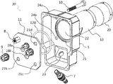
- FIG. 2 illustrates an exploded perspective view of an inner part assembly 30 of a sealing system.
- the inner part assembly 30 comprises a box-shaped enclosure 1 having a slot 25 , a cavity 22 through which pipes or cables may be carried, holes 24 a and 24 b (two other not shown in the figures) through which screws may be inserted, an opening 23 , and an elongated cylinder 13 .
- a metal plate 11 having holes 21 b , 21 c and 21 d (hole 21 a is not shown).
- the metal plate 11 is used for sealing of the enclosure 1 by using an O-ring 120 that is placed in the slot 25 , and is pressed between the metal plate 11 and the enclosure 1 using four threaded screws (exampled by a screw 10 ).
- Each threaded screws passes through the corresponding hole in the enclosure 1 and the corresponding hole in the metal plate 11 and is secured with a respective nut (exampled by a nut 8 ).
- the plate 11 may, for example, be used for preventing a blast to the safety room interior environment in case of an external explosion.
- the box-shaped enclosure 1 , the plate base 6 and the extension cylinders, such cylinders 3 , 13 and 20 , can be made of plastic.
- the inner part 30 further supports water draining capabilities by using an auto-seal zero pressure check valve assembly 7 that is installed via the opening 23 in the bottom of the enclosure 1 in order to maintain drain water flow towards the room exterior.
- FIGS. 3 and 4 illustrate an auto-seal zero pressure check valve assembly 7 .
- FIGS. 3 and 4 While the known check valve operates with a high pressure fluid, the auto-seal zero pressure check valve assembly 7 , as shown in FIGS. 3 and 4 , can be operated with a low pressure fluid such as water draining from an air condition.
- FIG. 3 illustrates an exploded perspective view of the auto-seal zero pressure check valve assembly 7 and
- FIG. 4 illustrates a cross section view of the auto-seal zero pressure check valve assembly 7 .
- the auto-seal zero pressure check valve assembly 7 comprises a hose threaded nipple 76 , a spring 75 , a valve ball 74 , an O-ring 73 , and an open nut 72 . Further the auto-seal zero pressure check valve assembly 7 comprises a hollow pressing unit 71 having an end unit 77 with holes for allowing a fluid to drain from the hollow pressing unit 71 through the end unit 77 to the hose threaded nipple 76 and to the external area.
- the spring 75 is placed in a cavity 78 of the hose threaded nipple 76 , the valve ball 74 and the O-Ring 73 are placed on the spring 75 .
- the open nut 72 screws on the hose threaded nipple 76 and constantly pushing the O-ring 73 towards the valve ball 74 , the valve ball 74 is pushed towards the spring 75 .
- This position provides constantly sealing of an internal environment, such of a safety room, from an external environment.
- the sealing operates in a closed loop manner, as a pressure from the external environment pushes the valve ball 74 that increases its sealing forces toward the O-ring 73 making the sealing tighter.
- the closed loop operation makes it possible to support extremely low and extremely high pressure sealing with a single valve system.
- the pressing unit 71 is easily inserted through the open nut 72 into the auto-seal zero pressure check valve assembly 7 . In this position, the pressing unit 71 pushes the valve ball 74 back from the O-ring 73 allowing the draining water from the internal area flows from the hollow pressing unit 71 through the end unit 77 and through the hose threaded nipple 76 to the external area.
- the diameter of the end unit 77 is slightly bigger than the inner diameter of the O-Ring 73 , for maintaining the pressing unit 71 in place, and for preventing draining water, in a case of a block in a drain pipe and accumulation of water in the drain pipe, to leak into the inner side of a room.
- the pressing unit 71 can be manually removed easily by a user for sealing the interior room and for preventing gas or water to enter the inner side of the room.
- FIG. 5 illustrates an external part assembly 40 of a sealing system.
- the external part assembly 40 is optionally and installed in cases where there is a higher requirement to secure from shrapnel and blast.
- the external part assembly 40 is normally installed when there is a risk for a direct hit or direct blast on a wall.
- the external part assembly 40 comprises a structure having an elongated cylinder 3 and a plate base 6 .
- a flat metal plate 5 is attached to the plate base 6 using four spacers 4 a , 4 b , 4 c and 4 d , using four screws 12 a , 12 b , and 12 d (the fourth screw not shown in the figures) and respective nuts 2 a (Other 3 nuts are not shown in the figure).
- the spacers (such as 4 a , 4 b , 4 c and 4 d ) allow access to an opening 8 of the cylinder 3 while maintaining blast shrapnel protection.
- the flat metal plate 5 acts as a passive shield from shrapnel and preventing from the explosion blast to go directly to the cylinder 3 into the wall, thus reducing the blast impact on the metal plate 11 of the inner part assembly 30 .
- FIGS. 6 and 7 illustrate a cross section view of a sealing nipple system 90 in an open (unscrew) and close (screwed) position.
- FIG. 6 illustrates the sealing nipple system 90 wherein a pipe, cable or wire 95 inserted to a threaded hole in a metal plate 11 in one piece without a need of interfering with the pipe, cable or wire as it passes through a threaded hole.
- the sealing nipple system 90 comprises a threaded nipple 94 screwed on the metal plate 11 using a Dowty seal 93 for maintaining the sealing between a first surface of the metal plate 11 and a second surface of the threaded nipple 94 .
- the threaded nipple 94 having a flat edge 96 is configured to seal the pipe, cable or wire.
- the sealing nipple system 90 further comprises an O-ring 92 and a flare nut 91 having an internal chamfer 98 with an angle 97 .
- the flare nut 91 presses the O-ring 92 towards the threaded nipple 94 and screwing the threaded nipple 94 generating forces on the O-ring 92 in several directions, thus making the connection sealed.
- FIG. 7 illustrates the sealing nipple system 90 in screwed position.
- the flare nut 91 is fasten over the O-ring 92 , and tightened the O-ring 92 to the flat edge 96 of the threaded nipple 94 .
- the tightening generates a force F 1 on the O-ring 92 .
- force F 1 and of the angle 97 of the internal chamfer 98 the O-ring 92 is pushed towards the pipe 95 and to the flat edge 96 of the threaded nipple 94 .
- Forces F 2 and F 3 are equal, and the O-ring is surrounded with forces holding the pipe 95 together maintaining a high sealing capabilities.
- the angle 97 of the chamfer 98 is preferred to be 45 degrees as the forces F 1 , F 2 , F 3 and F 4 will split equally maintaining the sealing power equal in all directions.
- the material of the pipe has better sealing capabilities like a rubber electric cable and the angle of the chamfer can be adopted in order to divide the forces.
Abstract
Description
Claims (15)
Priority Applications (1)
| Application Number | Priority Date | Filing Date | Title |
|---|---|---|---|
| US16/290,910 US11221092B2 (en) | 2018-03-04 | 2019-03-03 | System and method for sealing wires, cables, pipes and drain holes through buffer |
Applications Claiming Priority (2)
| Application Number | Priority Date | Filing Date | Title |
|---|---|---|---|
| US201862638169P | 2018-03-04 | 2018-03-04 | |
| US16/290,910 US11221092B2 (en) | 2018-03-04 | 2019-03-03 | System and method for sealing wires, cables, pipes and drain holes through buffer |
Publications (2)
| Publication Number | Publication Date |
|---|---|
| US20190271415A1 US20190271415A1 (en) | 2019-09-05 |
| US11221092B2 true US11221092B2 (en) | 2022-01-11 |
Family
ID=66768865
Family Applications (1)
| Application Number | Title | Priority Date | Filing Date |
|---|---|---|---|
| US16/290,910 Active US11221092B2 (en) | 2018-03-04 | 2019-03-03 | System and method for sealing wires, cables, pipes and drain holes through buffer |
Country Status (2)
| Country | Link |
|---|---|
| US (1) | US11221092B2 (en) |
| IL (1) | IL265133B (en) |
Families Citing this family (3)
| Publication number | Priority date | Publication date | Assignee | Title |
|---|---|---|---|---|
| US10870990B1 (en) * | 2019-05-10 | 2020-12-22 | Peter Baruch Mueller | Closed panel building systems |
| CN113224709B (en) * | 2020-11-22 | 2022-04-12 | 胜利油田恒源电气有限责任公司 | Corrosion-resistant electric power fitting |
| CN113964759A (en) * | 2021-10-15 | 2022-01-21 | 上海江南长兴造船有限责任公司 | Double-fuel-vessel fuel tank cable penetrating device and using method thereof |
Citations (29)
| Publication number | Priority date | Publication date | Assignee | Title |
|---|---|---|---|---|
| US3232644A (en) * | 1963-09-05 | 1966-02-01 | Bendix Corp | Twist lock check valve |
| US3489440A (en) | 1966-04-18 | 1970-01-13 | Lyckeaborgs Bruk Ab | Tight lead-through inlet frame device |
| US3568977A (en) * | 1969-01-29 | 1971-03-09 | Illinois Tool Works | Valve assembly |
| US4192338A (en) * | 1978-05-15 | 1980-03-11 | Gerulis Benedict R | Hydraulic lock-out device |
| US4197875A (en) | 1978-05-16 | 1980-04-15 | Liquid Metronics Incorporated | Ball check valve |
| US4664144A (en) * | 1986-04-14 | 1987-05-12 | Deere & Company | Fuel recovery system for dual tanks |
| US5107890A (en) | 1990-05-03 | 1992-04-28 | Huron Products Industries, Inc. | Ball check valve |
| US5275196A (en) * | 1993-04-19 | 1994-01-04 | Hugh A. Mitchell | Pressure relief valve for tire rim |
| US6105610A (en) * | 1998-02-13 | 2000-08-22 | Liquid Metronics Incorporated | Cartridge valve with triple sequential seal |
| US6299413B1 (en) * | 2000-06-14 | 2001-10-09 | Ingersoll-Rand Company | Pump having a bleeding valve |
| US6521840B1 (en) | 1999-10-08 | 2003-02-18 | Roxtec Ab | Cable penetration device |
| US6558141B2 (en) * | 2001-04-12 | 2003-05-06 | Ingersoll-Rand Company | Packing assembly and reciprocating plunger pump incorporating same |
| US6721483B2 (en) * | 2000-10-17 | 2004-04-13 | Preformed Line Products Company | Cable closure and assembly |
| US7025087B2 (en) * | 2001-06-21 | 2006-04-11 | Graco Minnesota Inc. | Reciprocating piston pump adjustable inlet ball travel |
| US20060188380A1 (en) * | 2005-02-18 | 2006-08-24 | Strong Christopher L | Pump having independently releasable ends |
| US7311118B2 (en) * | 2004-03-30 | 2007-12-25 | Parker-Hannifin Corporation | Floating ball check valve |
| US20080178948A1 (en) * | 2007-01-26 | 2008-07-31 | Max Wilmshurst | Safety Leaky Check Valve for Slow Bleed of Compressed Air |
| WO2008091219A1 (en) | 2007-01-25 | 2008-07-31 | Roxtec Ab | Lead through device for cables or pipes |
| US7806142B2 (en) * | 2007-06-27 | 2010-10-05 | Teleflex Canada Inc. | Combined relief valve and check valve |
| US20110255996A1 (en) * | 2010-04-20 | 2011-10-20 | James Wickstead | Inverted fluid dispensing pump and dispensing system, and method of using an inverted pump |
| US8511716B2 (en) * | 2008-04-29 | 2013-08-20 | Voss Automotive Gmbh | Connection device for fluid lines in the region of a wall duct and wall element |
| IL218946A (en) | 2012-03-29 | 2013-11-28 | Oren Skurnik | Apparatus for conveying piping and wiring into a fortified room |
| US8869824B2 (en) * | 2007-08-30 | 2014-10-28 | Perlick Corporation | Check valve and shut-off reset device for liquid delivery systems |
| US20170292506A1 (en) * | 2016-04-11 | 2017-10-12 | Graco Minnesota Inc. | Paint sprayer pump cartridge |
| US9803762B2 (en) * | 2016-03-03 | 2017-10-31 | Chung Hyo Kim | Ball check valve apparatus |
| US9954349B2 (en) * | 2015-09-25 | 2018-04-24 | The Boeing Company | Two-part snap-together feedthroughs |
| US20180291891A1 (en) * | 2015-11-11 | 2018-10-11 | Graco Minnesota Inc. | Ball Cage with Directed Flow Paths for a Ball Pump |
| US10125885B2 (en) * | 2016-06-03 | 2018-11-13 | Holimay Corporation | Check valve mounting structure |
| US10591075B2 (en) * | 2015-12-21 | 2020-03-17 | Graco Minnesota Inc. | Shock absorbing and wear resistant ball check seat for abrasive media |
-
2019
- 2019-03-03 IL IL265133A patent/IL265133B/en active IP Right Grant
- 2019-03-03 US US16/290,910 patent/US11221092B2/en active Active
Patent Citations (29)
| Publication number | Priority date | Publication date | Assignee | Title |
|---|---|---|---|---|
| US3232644A (en) * | 1963-09-05 | 1966-02-01 | Bendix Corp | Twist lock check valve |
| US3489440A (en) | 1966-04-18 | 1970-01-13 | Lyckeaborgs Bruk Ab | Tight lead-through inlet frame device |
| US3568977A (en) * | 1969-01-29 | 1971-03-09 | Illinois Tool Works | Valve assembly |
| US4192338A (en) * | 1978-05-15 | 1980-03-11 | Gerulis Benedict R | Hydraulic lock-out device |
| US4197875A (en) | 1978-05-16 | 1980-04-15 | Liquid Metronics Incorporated | Ball check valve |
| US4664144A (en) * | 1986-04-14 | 1987-05-12 | Deere & Company | Fuel recovery system for dual tanks |
| US5107890A (en) | 1990-05-03 | 1992-04-28 | Huron Products Industries, Inc. | Ball check valve |
| US5275196A (en) * | 1993-04-19 | 1994-01-04 | Hugh A. Mitchell | Pressure relief valve for tire rim |
| US6105610A (en) * | 1998-02-13 | 2000-08-22 | Liquid Metronics Incorporated | Cartridge valve with triple sequential seal |
| US6521840B1 (en) | 1999-10-08 | 2003-02-18 | Roxtec Ab | Cable penetration device |
| US6299413B1 (en) * | 2000-06-14 | 2001-10-09 | Ingersoll-Rand Company | Pump having a bleeding valve |
| US6721483B2 (en) * | 2000-10-17 | 2004-04-13 | Preformed Line Products Company | Cable closure and assembly |
| US6558141B2 (en) * | 2001-04-12 | 2003-05-06 | Ingersoll-Rand Company | Packing assembly and reciprocating plunger pump incorporating same |
| US7025087B2 (en) * | 2001-06-21 | 2006-04-11 | Graco Minnesota Inc. | Reciprocating piston pump adjustable inlet ball travel |
| US7311118B2 (en) * | 2004-03-30 | 2007-12-25 | Parker-Hannifin Corporation | Floating ball check valve |
| US20060188380A1 (en) * | 2005-02-18 | 2006-08-24 | Strong Christopher L | Pump having independently releasable ends |
| WO2008091219A1 (en) | 2007-01-25 | 2008-07-31 | Roxtec Ab | Lead through device for cables or pipes |
| US20080178948A1 (en) * | 2007-01-26 | 2008-07-31 | Max Wilmshurst | Safety Leaky Check Valve for Slow Bleed of Compressed Air |
| US7806142B2 (en) * | 2007-06-27 | 2010-10-05 | Teleflex Canada Inc. | Combined relief valve and check valve |
| US8869824B2 (en) * | 2007-08-30 | 2014-10-28 | Perlick Corporation | Check valve and shut-off reset device for liquid delivery systems |
| US8511716B2 (en) * | 2008-04-29 | 2013-08-20 | Voss Automotive Gmbh | Connection device for fluid lines in the region of a wall duct and wall element |
| US20110255996A1 (en) * | 2010-04-20 | 2011-10-20 | James Wickstead | Inverted fluid dispensing pump and dispensing system, and method of using an inverted pump |
| IL218946A (en) | 2012-03-29 | 2013-11-28 | Oren Skurnik | Apparatus for conveying piping and wiring into a fortified room |
| US9954349B2 (en) * | 2015-09-25 | 2018-04-24 | The Boeing Company | Two-part snap-together feedthroughs |
| US20180291891A1 (en) * | 2015-11-11 | 2018-10-11 | Graco Minnesota Inc. | Ball Cage with Directed Flow Paths for a Ball Pump |
| US10591075B2 (en) * | 2015-12-21 | 2020-03-17 | Graco Minnesota Inc. | Shock absorbing and wear resistant ball check seat for abrasive media |
| US9803762B2 (en) * | 2016-03-03 | 2017-10-31 | Chung Hyo Kim | Ball check valve apparatus |
| US20170292506A1 (en) * | 2016-04-11 | 2017-10-12 | Graco Minnesota Inc. | Paint sprayer pump cartridge |
| US10125885B2 (en) * | 2016-06-03 | 2018-11-13 | Holimay Corporation | Check valve mounting structure |
Also Published As
| Publication number | Publication date |
|---|---|
| IL265133B (en) | 2020-11-30 |
| US20190271415A1 (en) | 2019-09-05 |
| IL265133A (en) | 2019-05-30 |
Similar Documents
| Publication | Publication Date | Title |
|---|---|---|
| US11221092B2 (en) | System and method for sealing wires, cables, pipes and drain holes through buffer | |
| US20210324969A1 (en) | Vent with relief valve | |
| JP2003227227A (en) | Modular bulkhead (capable of detecting airtightness) for airtightly pulling in cable and pipe by passing through part of all kinds of buildings | |
| WO2007100106A1 (en) | Fluid equipment unit structure | |
| US11322919B2 (en) | Cable entry device for electrical cable housed in a conduit | |
| RU2697585C2 (en) | Sealing device | |
| US8491017B2 (en) | Fitting structure including a pair of connection pipes and a clamp ring | |
| AU2021328255B2 (en) | Compact valve assembly | |
| ES2621206T3 (en) | Housing and compression procedure of one or more elastic modules for cable entries, pipe penetrations or similar elements | |
| EP1443253B1 (en) | Pulsation damper for absorbing pressure pulsations in a high pressure hydraulic system | |
| US6935613B1 (en) | Compact integrated flanged isolator ball valve | |
| BRPI0519151B1 (en) | VALVE BODY | |
| US20210010731A1 (en) | Integrated sensor and service port with anti-blowback feature for hvac equipment or hvac system | |
| KR100659369B1 (en) | Pipe cap for testing leakage of water | |
| JP3334066B2 (en) | Valve device | |
| GB2073391A (en) | Refrigeration installation | |
| US8911247B2 (en) | Quick connector system luminiary fitting | |
| CN211373909U (en) | Pressure regulator for FRL device | |
| WO2019219827A1 (en) | Valve and grounding assembly for telecommunications closures | |
| US11054155B2 (en) | Resin-coated aluminum pipe connector for air conditioner outdoor unit | |
| US10461464B1 (en) | Bi-directional, rotating, pressure bulkhead penetrator | |
| US20230271044A1 (en) | Dry pipe manifold systems and methods | |
| US10571044B2 (en) | Adapter system for a check valve | |
| US20190113159A1 (en) | Sealing device and medical device with at least one sealing device | |
| KR200387266Y1 (en) | Flowing backward prevention connection valve |
Legal Events
| Date | Code | Title | Description |
|---|---|---|---|
| AS | Assignment |
Owner name: ZOHAR DIUK LTD., ISRAEL Free format text: ASSIGNMENT OF ASSIGNORS INTEREST;ASSIGNORS:NAVON, EDO;NAVON, DROR;REEL/FRAME:048486/0442 Effective date: 20190227 |
|
| FEPP | Fee payment procedure |
Free format text: ENTITY STATUS SET TO UNDISCOUNTED (ORIGINAL EVENT CODE: BIG.); ENTITY STATUS OF PATENT OWNER: SMALL ENTITY |
|
| FEPP | Fee payment procedure |
Free format text: ENTITY STATUS SET TO SMALL (ORIGINAL EVENT CODE: SMAL); ENTITY STATUS OF PATENT OWNER: SMALL ENTITY |
|
| STPP | Information on status: patent application and granting procedure in general |
Free format text: DOCKETED NEW CASE - READY FOR EXAMINATION |
|
| STPP | Information on status: patent application and granting procedure in general |
Free format text: NON FINAL ACTION MAILED |
|
| STPP | Information on status: patent application and granting procedure in general |
Free format text: RESPONSE TO NON-FINAL OFFICE ACTION ENTERED AND FORWARDED TO EXAMINER |
|
| STPP | Information on status: patent application and granting procedure in general |
Free format text: RESPONSE TO NON-FINAL OFFICE ACTION ENTERED AND FORWARDED TO EXAMINER |
|
| STPP | Information on status: patent application and granting procedure in general |
Free format text: FINAL REJECTION MAILED |
|
| STPP | Information on status: patent application and granting procedure in general |
Free format text: RESPONSE AFTER FINAL ACTION FORWARDED TO EXAMINER |
|
| STPP | Information on status: patent application and granting procedure in general |
Free format text: ADVISORY ACTION MAILED |
|
| STPP | Information on status: patent application and granting procedure in general |
Free format text: DOCKETED NEW CASE - READY FOR EXAMINATION |
|
| STPP | Information on status: patent application and granting procedure in general |
Free format text: NON FINAL ACTION MAILED |
|
| STPP | Information on status: patent application and granting procedure in general |
Free format text: RESPONSE TO NON-FINAL OFFICE ACTION ENTERED AND FORWARDED TO EXAMINER |
|
| STPP | Information on status: patent application and granting procedure in general |
Free format text: NOTICE OF ALLOWANCE MAILED -- APPLICATION RECEIVED IN OFFICE OF PUBLICATIONS |
|
| STPP | Information on status: patent application and granting procedure in general |
Free format text: PUBLICATIONS -- ISSUE FEE PAYMENT VERIFIED |
|
| STCF | Information on status: patent grant |
Free format text: PATENTED CASE |