JP2007106359A - Center mount structure of vehicular propeller shaft - Google Patents
Center mount structure of vehicular propeller shaft Download PDFInfo
- Publication number
- JP2007106359A JP2007106359A JP2005301828A JP2005301828A JP2007106359A JP 2007106359 A JP2007106359 A JP 2007106359A JP 2005301828 A JP2005301828 A JP 2005301828A JP 2005301828 A JP2005301828 A JP 2005301828A JP 2007106359 A JP2007106359 A JP 2007106359A
- Authority
- JP
- Japan
- Prior art keywords
- propeller shaft
- bearing
- cylinder member
- outer race
- joint
- Prior art date
- Legal status (The legal status is an assumption and is not a legal conclusion. Google has not performed a legal analysis and makes no representation as to the accuracy of the status listed.)
- Pending
Links
Images


Abstract
Description
本発明は、エンジンの駆動力を駆動輪に伝達するプロペラシャフトを支持するセンターマウント構造に関する。 The present invention relates to a center mount structure that supports a propeller shaft that transmits engine driving force to driving wheels.
一般に、四輪駆動車(AWD)やフロントエンジンリヤドライブ(FR)の車両の動力伝達系は、車体に対して前後方向に配置するプロペラシャフトの前端部が車体前部に搭載したエンジン側の出力軸に連結すると共に、後端部がデファレンシャル装置を介して駆動輪である後輪の駆動軸に連結している。 In general, the power transmission system of a four-wheel drive vehicle (AWD) or front engine rear drive (FR) vehicle has an engine-side output mounted on the front of the vehicle body at the front end of a propeller shaft disposed in the front-rear direction with respect to the vehicle body. In addition to being connected to the shaft, the rear end portion is connected to the drive shaft of the rear wheel, which is the drive wheel, via a differential device.
一方、プロペラシャフトは、主に高速回転時における危険回転速度、即ちプロペラシャフトの曲げ固有振動数とプロペラシャフト回転周波数が一致して共振を生じてプロペラシャフトの振動幅が大きくなりプロペラシャフトが破壊するときの限界回転速度を、プロペラシャフトの曲げ剛性を高めて使用車速領域外に上げるためにジョイントで2分割されている。 On the other hand, the propeller shaft mainly causes a dangerous rotation speed at the time of high-speed rotation, that is, the resonance frequency of the propeller shaft and the propeller shaft rotation frequency coincide with each other, thereby causing resonance and increasing the vibration width of the propeller shaft, thereby destroying the propeller shaft. In order to increase the bending speed of the propeller shaft and increase it outside the vehicle speed range, the limit rotational speed is divided into two at the joint.
この2分割して構成されたプロペラシャフトは、例えば、図6に示すようにフロントプロペラシャフト102と、フロントプロペラシャフト102の後端部にジョイント105を介して連結したリヤプロペラシャフト103によって形成され、プロペラシャフト101の前端部がユニバーサルジョイント107を介してエンジン及び変速機を備えたパワーユニットの出力軸に連結すると共に、リヤプロペラシャフト103の後端部がユニバーサルジョイント108を介して駆動輪である後輪用のデファレンシャル装置109に連結されている(例えば、特許文献1参照)。
The propeller shaft constituted by dividing into two is formed by, for example, a
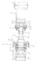
このようなプロペラシャフト101は、フロントプロペラシャフト102の後端部をセンターマウント110によって車体120の下面に支持している。このセンターマウント110の一例を図7を参照して説明する。
In such a
フロントプロペラシャフト102の後端部を支持するセンターマウント110は、フロントプロペラシャフト102の後端部に結合されたジョイント105のジョイントシャフト106に嵌合するインナレース111a、アウタレース111b、インナレース111aとアウタレース111bとの間で転動する複数のボール111cを有するベアリング111と、ベアリング111の外周に嵌合して固定された内筒部材112と、この内筒部材112の外周にゴム等の弾性材からなるインシュレータ113を介して連結された外筒部材114と、この外筒部材114を車体の下面に取り付けるブラケット123を有している。
The
ベアリング111は、そのインナレース111aがジョイントシャフト106の主軸部106aに嵌合して支持されている。
The
内筒部材112は、ベアリング111のアウタレース111bの外周面に本体部112aが嵌合し、この本体部112aから拡径して環状に形成された大径部112bと、本体部112aからアウタレース111bの後面に沿って縮径して円筒状に延在する小径部112cが一体形成された軸方向に長い略円筒状に形成されている。
The
内筒部材112の大径部112b内に断面略C字状或いはU字状で環状に形成されたリテーナ119が設けられている。ベアリング111の両側にリテーナ119とジョイントシャフト106の間及び内筒部材112の小径部112cとジョイントシャフト106との間にリング状のオイルシール115a、115bが配設されている。
A
このように構成されたプロペラシャフト101は、通常の走行において、パワーユニットからの回転トルクがユニバーサルジョイント107を介してフロントプロペラシャフト102に伝達され、フロントプロペラシャフト102からジョイント105を介してリヤプロペラシャフト103に伝達され、リヤプロペラシャフト103からユニバーサルジョイント108を介してデファレンシャル装置109に伝達される。
In the
この走行に際し、プロペラシャフト101の中間部であるフロントプロペラシャフト102とリヤプロペラシャフト103を連結するジョイント105のジョイントシャフト106をセンターマウント110を介して車体120に回転自在に支承することによって、プロペラシャフト101が高速回転した際の振れが減衰支持されて車両の振動及び騒音が抑制される。
During this travel, the propeller shaft is rotatably supported on the
ベアリングの持つ一般的な性質として、アウタレース等の軌道輪とボールとが弾性接触により荷重を受けるので、「ばね」の性質を有しており、回転体がベアリングにより支持されている場合回転体を質量とした振動系が存在し、ベアリングに起因して一種の自励振動と推定される回転軸のスラスト振動を生じることが一般に知られている(例えば、非特許文献1参照)。 As a general property of bearings, a raceway such as an outer race and a ball are subjected to a load by elastic contact, so it has a “spring” property, and when a rotating body is supported by a bearing, the rotating body is It is generally known that there is a vibration system with a mass, and a thrust vibration of a rotating shaft that is estimated to be a kind of self-excited vibration is caused by a bearing (for example, see Non-Patent Document 1).
ここで、プロペラシャフトのセンターベアリングを例にベアリングが持っているスラスト(アキシャル)方向ばね特性について説明する。フロントプロペラシャフト102の後端部に配設されたジョイント105のジョイントシャフト106を支持するセンターマウント110のベアリング111は、図8(a)に模式的に示すようにインナレース111aがジョイントシャフト106に嵌合し、アウタレース111bが内筒部材112に嵌合してインシュレータ113によって外筒部材114に弾性支持され、インナレース111aの軌道面とアウタレース111bの軌道面との間に転動体となるボール111cが複数嵌合配置されている。ベアリング111には、高速高負荷回転時の焼き付きを防止するため、インナレース111a及びアウタレース111bの軌道面とボール111cの間に微小なラジアル隙間を設定してある。
Here, the thrust (axial) direction spring characteristic of the bearing will be described by taking the center bearing of the propeller shaft as an example. The
インナレース111aの軌道面とボール111c及びアウタレース111bの軌道面とボール111cは相対的にスラスト方向に移動して、この微小隙間が詰まった状態で互いに弾性接触し、図8(b)に示すようにインナレース111aとボール111cとの接触点とアウタレース111aとボール111cとの接触点が軸方向にオフセットする接触角αを有することから、ベアリング111にスラスト方向力Fxが働いた場合、この接触角α方向に所謂弾性接触面圧Fx/sinαが作用する。このスラスト力Fxと接触面圧による弾性変形歪みδpに伴うスラスト方向相対変位δp/sinαとの関係によりベアリング111のインナレース111aとアウタレース111bの間でスラスト方向のばね作用が生じる。弾性歪みδpは、球体と円環との弾性接触問題として求められる。また、弾性接触ばねKbrgは、
Kbrg=Fx・sinα/δp
である。
The raceway surface of the inner race 111a and the
Kbrg = Fx · sin α / δp
It is.
このため、プロペラシャフト101のセンターマウントに用いられるベアリング111については、この弾性接触ばねKbrgとインシュレータKinsをばねとし、アウタレース111bと内筒部材112の合計質量Moutをマスとする固有振動数f0_brgを有している。
Therefore, for the
![]()
![]()
次に、ベアリングの軸振動について説明する。 Next, the shaft vibration of the bearing will be described.
プロペラシャフト101において、パワーユニットおよびプロペラシャフト101の回転によって、振動がプロペラシャフト101とベアリング111に伝達されると、アウタレース111bに軸方向のスラスト力Psが周期的に繰り返し付与されることが起こり得る。プロペラシャフト101の場合も、この繰り返し振動により、前記固有振動数にてベアリング軸方向振動が生じる振動系を有している。
In the
また、次に、ベアリングが持っているもう1つの本質的な特性である転動体通過振動について説明する。 Next, the rolling element passing vibration, which is another essential characteristic of the bearing, will be described.
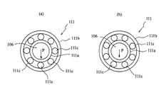
前記のようにベアリング111は、インナレース111a及びアウタレース111bの軌道面とボール111cの間に微小ラジアル隙間を有しているから、図10(a)及び図10(b)に模式的に示すようにベアリング111のインナレース111aにプロペラシャフト101の自重荷重Pが付加された状態で、プロペラシャフト101の回転に伴ってインナレース111aが回転するとボール111cの周方向位置の相違によってベアリング111の隙間分布状態が異なりアウタレース111bの幾何学的変位を誘発し、ボール111cとインナレース111a及びアウタレース111bとの幾何学的変位量の変化にともなってインシュレータ113を介して支持されたアウタレース111b及び内筒部材112が上下に振動する、いわゆる転動体通過振動が発生する。即ち図10(a)のようにプロペラシャフト101、より正確にはジョイントシャフト106からの荷重Pの真下にボール111cがくるときと、図10(b)のように荷重方向Pに対して対称位置にボール111cがくるときでは、プロペラシャフト101の回転中心に対するアウタレース111b及び内筒部材112が上下に相対移動する。
Since the
この変位量はベアリングのインナ、アウタレース軌道溝径、ボール径、ボール数、ラジアル隙間から幾何学的に求めることができる。図10の(a)の変位Yminと(b)の変位Ymaxの差δY=Ymax−Yminが振動変位である。 The amount of displacement can be obtained geometrically from the bearing inner, outer race raceway groove diameter, ball diameter, number of balls, and radial clearance. A difference δY = Ymax−Ymin between the displacement Ymin in FIG. 10A and the displacement Ymax in FIG. 10B is the vibration displacement.
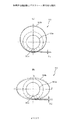
定性的には、図からわかるように、ラジアル隙間が大きいほどボール111cの公転による上下変位は大きくなる。この転動体通過振動はアウタレース111bの真円度が大きく影響する。これを図11(a)及び図11(b)により説明する。図11(b)の真円度は図11(a)のそれより悪い。真円度が悪いとボール111cの周方向位置の相違によるインナレース111a及びアウタレース111bとの幾何学的変位量が大きくなる。
Qualitatively, as can be seen from the figure, the larger the radial gap, the greater the vertical displacement due to the revolution of the
なぜなら、真円度の悪化としてアウタレース111bの軌道が楕円状にひしゃげた形状で、その短径側が上下方向に位置した場合を想定すると、ボールの接触部位となる軌道面の最大曲率半径ρは、軌道となる楕円の長径2a、短径2bとして、
ρ=a2/b
の式で表され、ひしゃげた形状ほど長径、短径比が大きく曲率半径ρが大きくなるから、ラジアル隙間が大きいことと真円度精度が悪いことの幾何学的効果は等しいからである。また、このことは、上記の幾何学的変位による説明ばかりでなく、図9のように、ボール111cとアウタレース111bの軌道面との間の弾性接触歪みによっても説明できる。すなわち、ラジアル隙間が大きく、したがってアウタレース111bの接触曲率が大きいほど、弾性接触変形歪みが大きくなり、ボール111cの公転による上下変位が相対的に大きくなる。弾性歪み量は、ボール111c配置による分担荷重を考慮して、ボール111cとアウタレール111bとの弾性接触問題として求められる。
This is because, assuming that the
ρ = a 2 / b
This is because the longer diameter and the shorter diameter ratio are larger and the curvature radius ρ is larger as the slender shape is larger, and the geometrical effects of the large radial gap and the poor roundness accuracy are equal. This can be explained not only by the geometric displacement described above, but also by the elastic contact strain between the
これらプロペラシャフト101の回転により、ボールが軌道面を公転する際のアウタレース111bの上下変位に起因する振動が転動体通過振動である。
この転動体通過振動の次数nは
n=1/2・Z(1−Dw/Dp)
ここに、Z:ボール数、Dw:ボール径、Dp:ベアリングピッチ円径
で表され、ベアリング1回の回転でn回の上下振動が発生する。
Due to the rotation of the
The order n of this rolling element passing vibration is n = 1/2 · Z (1-Dw / Dp)
Here, Z is the number of balls, Dw is the ball diameter, Dp is the bearing pitch circle diameter, and n vertical vibrations are generated by one rotation of the bearing.
また、前述のように、プロペラシャフト101においては、ベアリング軸方向特性に起因するアウタレース111b及び内筒部材112の振動は、アウタレース111b及び比較的質量の大きな内筒部材112の質量Moutをマスとし、ベアリングの弾性接触剛性Kbrgとインシュレータ113Kinsによってばね定数が定められた固有振動数f0_brgの振動系が形成される。
Further, as described above, in the
![]()
![]()
一方、ここで、発明者は鋭意研究の結果、パワーユニットからの回転トルクがユニバーサルジョイント107を介して回転駆動されるフロントプロペラシャフト102においても、ユニバーサルジョイント112の軸剛性Kjointを主たるばねとしフロントプロペラシャフト102の質量Mpelaをマスとしてフロントプロペラシャフト102が軸方向に振動する振動系が形成されていることを究明した。この振動の固有振動数f0_pelaは以下の式で表される。
On the other hand, as a result of intensive research, the inventor also uses the axial rigidity Kjoint of the
![]()
![]()
このようにフロントプロペラシャフト102の軸方向の振動によってベアリング111のインナレース111aが軸方向に振動すると、インナレース111aの軸方向の振動に伴ってインナレース111aとボール111cとの接触点とアウタレース111bとボール111cとの接触点が軸方向にオフセットする接触角αによる接触ばねを有することからボール111cを介してアウタレース111bに軸方向のスラスト力が周期的に繰り返し付与され、このスラスト力の付与によりインシュレータ113を介して支持されたアウタレース111b及び内筒部材112がスラスト方向に振動する。即ちフロントプロペラシャフト102の軸方向の振動に起因してアウタレース111c及び内筒部材112を質量(マス)とする振動系が形成される。
Thus, when the inner race 111a of the
ここで、発明者は鋭意研究実験の結果、これらフロントプロペラシャフト102のベアリング111のアウタレース111b及び内筒部材112の軸振動固有値f0_brgと、フロントプロペラシャフトの軸振動固有値f0_pelaとが比較的近似した値であり、これら近似した振動周波数の固有値に起因する共振により車両の振動及び騒音を招き、乗り心地及び居住性に影響することを究明した。また、ベアリング111におけるアウタレース111bを嵌合保持する内筒部材112は一般に鉄板をプレス加工して円筒状に形成することから、加工時のスプリングバック等により加工精度、即ち真円度を確保することが困難である。この真円度の精度が確保できない内筒部材112にアウタレース111bを圧入すると、内筒部材112、特に本体部112aの成形精度が圧入時にアウタレース111bに転写してアウタレース111bの真円度に影響し、ベアリング111の転動体通過振動を増大させる要因であることを究明した。
Here, as a result of earnest research experiments, the inventor compared the axial vibration eigenvalue f 0 _brg of the
従って、これらに着目してなされた本発明の目的は、プロペラシャフトの回転及び軸方向の振動に起因するベアリング及び内筒部材の振動を抑制して車両の振動及び騒音の低減を図り、乗り心地及び居住性の向上が確保できる車両用プロペラシャフトのセンターマウント構造を提供することにある。 Accordingly, an object of the present invention made by paying attention to these is to reduce the vibration and noise of the vehicle by suppressing the vibration of the bearing and the inner cylinder member due to the rotation of the propeller shaft and the vibration in the axial direction. Another object of the present invention is to provide a center mount structure for a propeller shaft for a vehicle that can ensure improvement in habitability.
上記目的を達成する請求項1に記載の車両用プロペラシャフトのセンターマウント構造の発明は、ジョイントを介してフロントプロペラシャフトの後端部とリヤプロペラシャフトの前端部が連結され、フロントプロペラシャフトの前端部がユニバーサルジョイントによりパワーユニットの出力軸に連結されリヤプロペラシャフトの後端部がジョイントによりデファレンシャル装置に連結されたプロペラシャフトのセンターマウント構造において、上記フロントプロペラシャフトの後端部を嵌合支持するインナレースとアウタレース及び該インナレースとアウタレースの各軌道面間に転動可能に配置された複数のボールを備えたベアリングと、該ベアリングのアウタレースを収容して嵌合保持する内筒部材と、車体に取り付け支持された外筒部材と、上記内筒部材と外筒部材との間に介装された弾性材からなるインシュレータとを備え、上記内筒部材が鉄系材料より軽量で成形性に優れると共に成形精度が確保できる材料によって形成されたことを特徴とする。
In the invention of the center mount structure for a propeller shaft for a vehicle according to
請求項2に記載の発明は、請求項1の車両用プロペラシャフトのセンターマウント構造において、上記内筒部材は、アルミニウム系合金によって形成されたことを特徴とする。 According to a second aspect of the present invention, in the center mount structure for a propeller shaft for a vehicle according to the first aspect, the inner cylindrical member is made of an aluminum-based alloy.
請求項3に記載の発明は、請求項2の車両用プロペラシャフトのセンターマウント構造において、上記ベアリングが鉄系材料によって形成され、上記内筒部材は、上記ベアリングのアウタレースを保持する円筒状の本体部及び該本体部の両端にそれぞれ延設された第1延在部及び第2延在部を有する円筒状であって、上記ベアリングを隔ててフロントプロペラシャフトと上記第1延在部及びフロントプロペラシャフトと上記第2延在部の各間をそれぞれ水密的にシールするシール手段を備えたことを特徴とする。 According to a third aspect of the present invention, in the center mount structure for a propeller shaft for a vehicle according to the second aspect, the bearing is formed of a ferrous material, and the inner cylindrical member is a cylindrical main body that holds an outer race of the bearing A front propeller shaft, the first extension portion, and the front propeller with a bearing therebetween, the first extension portion and the second extension portion extending respectively at both ends of the main portion and the main portion. Sealing means for watertightly sealing between the shaft and each of the second extending portions is provided.
請求項4に記載の発明は、請求項2の車両用プロペラシャフトのセンターマウント構造において、上記ベアリングが鉄系材料によって形成され、上記内筒部材は、上記ベアリングのアウタレースを保持する円筒状の本体部及び該本体部の両端にそれぞれ延接された第1延在部及び第2延在部を有する円筒状であって、上記第1延在部に嵌入する円筒状の大径部及び該大径部に連続する円筒状の小径部を有する断面略C字状乃至U字状で環状に連続するリテーナと、上記第2延在部とプロペラシャフトの間を水密的にシールする第1シール部材と、上記リテーナの小径部とプロペラシャフトの間を水密的にシールする第2シール部材と、上記リテーナと第1延在部の間を水密的にシールする第3シール部材と、を備えたことを特徴とする。 According to a fourth aspect of the present invention, in the center mount structure for a propeller shaft for a vehicle according to the second aspect, the bearing is formed of a ferrous material, and the inner cylindrical member is a cylindrical main body that holds an outer race of the bearing. And a cylindrical large-diameter portion having a first extending portion and a second extending portion that are respectively extended at both ends of the body portion and the main body portion, the cylindrical large-diameter portion being fitted into the first extending portion, and the large portion A retainer that has an approximately C-shaped or U-shaped cross section having a cylindrical small-diameter portion continuous to the diameter portion and that is annularly continuous, and a first seal member that seals water tightly between the second extension portion and the propeller shaft. And a second seal member for watertight sealing between the small diameter portion of the retainer and the propeller shaft, and a third seal member for watertight sealing between the retainer and the first extension portion. It is characterized by.
請求項5に記載の発明は、請求項1の車両用プロペラシャフトのセンターマウント構造において、上記内筒部材は、樹脂材料によって形成されたことを特徴とする。 According to a fifth aspect of the present invention, in the center mount structure for a propeller shaft for a vehicle according to the first aspect, the inner cylinder member is formed of a resin material.
請求項6に記載の発明は、請求項1〜5のいずれか1項の車両用プロペラシャフトのセンターマウント構造において、上記フロントプロペラシャフトの後端部に代えてフロントプロペラシャフトの後端部に設けられたジョイントのジョイントシャフトをベアリングのインナレースで嵌合支持することを特徴とする。 According to a sixth aspect of the present invention, in the center mount structure for a propeller shaft for a vehicle according to any one of the first to fifth aspects, the rear end portion of the front propeller shaft is provided instead of the rear end portion of the front propeller shaft. The joint shaft of the joint is fitted and supported by the inner race of the bearing.
請求項1の発明によると、ベアリングのアウタレースを保持する内筒部材を軽量で成形性に優れて高精度で成形可能な材料により形成することで、内筒部材の真円度が確保でき、内筒部材に保持されるアウタレースの真円度が維持されて、フロントプロペラシャフトの回転に伴う転動体通過振動を抑制することができる。また、内筒部材の軽量化に伴ってフロントプロペラシャフトのアウタレース及び内筒部材の軸振動固有値とフロントプロペラシャフトの軸振動固有値との差を大幅に大きくして分離することができる。これにより互いの振動固有値を分離することにより共振の発生を有効的に回避することができて車両の振動及び騒音を抑制されて乗り心地及び居住性が向上する。 According to the first aspect of the present invention, the inner cylinder member that holds the outer race of the bearing is formed of a material that is lightweight, excellent in formability, and can be molded with high accuracy, thereby ensuring the roundness of the inner cylinder member. The roundness of the outer race held by the cylindrical member is maintained, and rolling element passing vibration accompanying rotation of the front propeller shaft can be suppressed. Further, with the weight reduction of the inner cylinder member, the difference between the outer race of the front propeller shaft and the axial vibration eigenvalue of the inner cylinder member and the axial vibration eigenvalue of the front propeller shaft can be greatly increased and separated. Thus, by separating the vibration eigenvalues from each other, the occurrence of resonance can be effectively avoided, and the vibration and noise of the vehicle are suppressed, so that riding comfort and comfort are improved.
請求項2の発明は、内筒部材の材質を具体的なアルミニウム系合金に特定するものであって、内筒部材を軽量で成形性に優れて高精度で成形可能なアルミニウム系合金によって形成することによって、請求項1の効果を達成することができる。
According to a second aspect of the present invention, the material of the inner cylinder member is specified as a specific aluminum-based alloy, and the inner cylinder member is formed of an aluminum-based alloy that is lightweight, excellent in formability, and can be formed with high accuracy. Thus, the effect of
内筒部材をアルミニウム系合金とすることのもう1つの効果を説明する。ベアリングは回転摩擦熱のためインナレース側温度がアウタレース側より上昇し熱膨張歪みの差によってラジアル隙間が減少する。その隙間減少量Stは
St=βFe・Di・ti+2βFe・Dw・tw
ここに、βFe:鉄の熱膨張係数、Di:インナレース軌道直径、Dw:ボール直径、ti:アウタレースとインナレースの温度差、tw:アウタレースとボールの温度差
で表される。ベアリングを鉄材の内筒部材に圧入する際の圧入しろはこの熱膨張による隙間減少をあらかじめ考慮して小さくしておく必要があった。アルミニウム系合金は熱伝導率が高く熱発散性に優れているので、内筒部材をアルミニウム系合金とすることによりベアリングの温度上昇を低減できるとともに、熱膨張係数が鉄材より大きいのでインナレース側膨張による隙間減少分をアウタレース圧入しめしろ減少によりラジアル隙間が補填されるので、長時間の運転においてもラジアル隙間がほぼ均一に保持されることになる。
Another effect of making the inner cylinder member an aluminum-based alloy will be described. The inner race side temperature rises from the outer race side due to the frictional heat of the bearing, and the radial gap decreases due to the difference in thermal expansion distortion. The clearance reduction St is St = β Fe · Di · ti + 2β Fe · Dw · tw
Here, β Fe : thermal expansion coefficient of iron, Di: inner race track diameter, Dw: ball diameter, ti: temperature difference between outer race and inner race, tw: temperature difference between outer race and ball. The press-fitting margin when press-fitting the bearing into the iron inner cylinder member needs to be reduced in consideration of the gap reduction due to this thermal expansion. Aluminum alloy has high thermal conductivity and excellent heat dissipation. By making the inner cylindrical member an aluminum alloy, the temperature rise of the bearing can be reduced, and the coefficient of thermal expansion is larger than that of iron, so the inner race side expansion. Since the radial clearance is compensated for by reducing the clearance due to the outer race press-fitting, the radial clearance is maintained substantially even during long-time operation.
請求項3の発明によると、ベアリングのアウタレースを嵌合保持する本体部の両端に延設された各第1延在部及び第2延在部とフロントプロペラシャフトの間をそれぞれシール手段によって水密的にシールすることによって、鉄系材料からなるベアリングのアウタレースとアルミニウム系合金からなる内筒部材との接触部間に外部から腐食媒体となる水分の浸入が防止され、異種金属のアウタレースと内筒部材との接触部における電食の発生が防止できる。 According to the third aspect of the present invention, the first propulsion portion and the second extension portion that are extended at both ends of the main body portion that fits and holds the outer race of the bearing and the front propeller shaft are respectively watertight by the sealing means. The outer race of the dissimilar metal and the inner cylinder member are prevented from entering between the contact portions of the outer race of the bearing made of iron-based material and the inner cylinder member made of the aluminum-based alloy. It is possible to prevent the occurrence of electrolytic corrosion at the contact portion.
請求項4の発明によると、円筒部材の第1延在部に嵌入するリテーナの小径部とプロペラシャフトとの間を第1シール部材により水密的にシールし、第2延在部とプロペラシャフトとの間を第2シール部材により水密的にシールし、リテーナと第1延在部との間を第2シール部材により水密的にシールすることによって、鉄系材料からなるベアリングのアウタレースとアルミニウム系合金からなる内筒部材との接触部間に外部から腐食媒体となる水分の浸入が防止され、異種金属のアウタレースと内筒部材との接触部における電食の発生が防止できる。 According to invention of Claim 4, between the small diameter part of the retainer fitted in the 1st extension part of a cylindrical member, and the propeller shaft is watertightly sealed by the 1st seal member, The 2nd extension part and the propeller shaft The outer race of the bearing made of iron-based material and the aluminum-based alloy are sealed with a second seal member between the retainer and the first extending portion with a second seal member. Intrusion of moisture as a corrosive medium from the outside is prevented between the contact portions with the inner cylinder member, and the occurrence of electrolytic corrosion at the contact portion between the outer race of the different metal and the inner cylinder member can be prevented.
請求項5の発明は、内筒部材の材質を具体的な樹脂材料に特定するものであって、嵌合相手形状に対する順応性が高い樹脂材料によって形成することによって、請求項1の効果を達成することができる。
The invention of claim 5 specifies the material of the inner cylinder member as a specific resin material, and achieves the effect of
請求項6の発明は、請求項1〜5におけるセンターマウント構造の他の具体的な構成を示すもので、ベアリングのインナレースによってフロントプロペラシャフトの後端部に設けられたジョイントのジョイントシャフトを嵌合支持するものである。
The invention of
以下、本発明の車両用プロペラシャフトのセンターマウント構造の実施の形態を図1乃至図5を参照して説明する。なお、各図において矢印Fは車体前方方向を示している。 Embodiments of a center mount structure for a vehicle propeller shaft according to the present invention will be described below with reference to FIGS. In each figure, an arrow F indicates the vehicle body front direction.
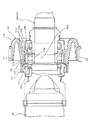
図1は四輪駆動車やフロントエンジンリヤドライブの駆動系に使用されるプロペラシャフト1の全体斜視図である。プロペラシャフト1は、フロントプロペラシャフト2と、フロントプロペラシャフト2の後端部にジョイント10を介して連結したリヤプロペラシャフト5によって構成される。フロントプロペラシャフト2の前端部がユニバーサルジョイント7を介して車体前部に搭載されたパワーユニットの出力軸に連結される一方、リヤプロペラシャフト5の後端部がユニバーサルジョイント8を介して駆動輪である後輪用のデファレンシャル装置に連結される。更に、フロントプロペラシャフト2とリヤプロペラシャフト5を連結するジョイント10を図2に車体下部の要部斜視図を示したようにセンターマウント30によって車体50の下面51に回転自在に支持している。
FIG. 1 is an overall perspective view of a
図3は、フロントプロペラシャフト2の後端部とリヤプロペラシャフト5の前端部とを連結するジョイント10及びセンタ−マウント30を示す図1のI−I線断面図であり、図4は図3のA部拡大図である。
3 is a cross-sectional view taken along the line II of FIG. 1, showing the joint 10 and the
ジョイント10は、図3に示すようにフロントプロペラシャフト2の後端部に結合されるジョイントシャフト11とリヤプロペラシャフト5の前端部に結合されるアウタケース20を有している。
As shown in FIG. 3, the joint 10 includes a
ジョイントシャフト11は、フロントプロペラシャフト2を形成するシャフトチューブ3の後端部3aに結合される円柱状の基部12と、この基部12の後端に段部12bを介して連続する主軸部13と、主軸部13の後端に段部13bを介して連続する先端軸部14が同軸上で一体に連続形成された略柱状に形成されている。ジョイントシャフト11の先端軸部14の先端部に、外周に軸方向に沿って伸びる複数のボール溝16aが形成された環状のインナレース16が固定されている。
The
一方、リヤプロペラシャフト5の前端部に結合されるアウタケース20は、円筒状に形成されたベース部21の内周面に、インナレース16の各ボール溝16aと対向して軸方向に延在する複数のボール溝21aが形成されている。
On the other hand, the
更に、ジョイントシャフト11の先端軸部14に配設されたインナレース16の外周に形成された各ボール溝16aに、リング状のゲージ25に保持されたボール26をそれぞれ嵌合させて装着する。このゲージ25及びボール26が装着されたインナレース16をアウタケース20内に挿入して、互いに対向するインナレース16の各ボール溝16aとベース部21の各ボール溝21aとの間にゲージ25に保持されたボール26を嵌合させる。
Further, the
このように構成されたジョイント10は、フロントプロペラシャフト2に取り付けられたジョイントシャフト11の先端軸部14に設けられたインナレース16、リヤプロペラシャフト5に取り付けられたアウタケース20、インナレース16及びアウタケース20のベース部21に形成されたボール溝16aと21aとの間に嵌合するボール26等によってフロントプロペラシャフト2とリヤプロペラシャフト5を等速で回転トルク伝達すると共に、互いの相対角度及び軸方向の相対移動を許容するダブルオフセットジョイント(DOJ)を構成する。
The joint 10 thus configured includes an
次にジョイント10を車体50の下面51に支持するセンターマウント30を図2及び図4を参照して説明する。
Next, the
センターマウント30は、ジョイントシャフト11に嵌合するベアリング31と、ベアリング31の外周に固定された内筒部材32と、この内筒部材32の外周にゴム等の弾性材からなるインシュレータ33を介して連結された外筒部材34と、この外筒部材34を車体51の下面51に取り付けるブラケット43を有している。
The
ベアリング31は、インナレース31aと、アウタレース31bと、インナレース31a及びアウタレース31bの各軌道面間に転動可能に配置された複数のボール31cを有し、そのインナレース31aがジョイントシャフト11の主軸部13に嵌合し、かつ主軸部13に形成されたクリップ溝に嵌合するクリップ36に係止された円筒状のスペーサ37と段差12bとの間に挟持して支持されている。
The
内筒部材32は、鉄系材料より軽量で成形性に優れると共に成形精度が確保できる材料、本実施の形態ではアルミニウム系合金材料製であって、ベアリング31のアウタレース31bの外周に本体部32aが嵌合し、この本体部32aの前端から段差部32bを介して拡径して環状に形成された第1延在部である大径部32cと、本体部32aの後端からアウタレース31bの後面に沿って縮径する段差部32dを介してスペーサ37に沿って円筒状に延在する第2延在部である小径部32eが一体形成された略円筒状に形成されている。この内筒部材32は、例えば生産性に優れたプレス成形によって成形され、プレス成形の際、成形性に優れてスプリングバック等の発生が極めて少ないアルミニウム系合金製であり容易に高精度で成形され、特にベアリング31のアウタレース31bが圧入される本体部32a等の真円度が良好に確保でき、結果的に圧入後のベアリングの真円度精度を大きく悪化させない。
The
内筒部材32の大径部32c内にアルミニウム系合金材料製で略断面C字状或いはU字状で環状に形成されたリテーナ39が設けられる。リテーナ39は大径部32cに圧入されて嵌合する大径部39aと、大径部39aの後端からテーパ面状に縮径される段差部39bと、段差部39bの後端からジョイントシャフト11に沿って前方に延在する円筒状の小径部39cとが連続一体形成されている。
A
ベアリング31の両側にリテーナ39の小径部39c及び内筒部材32の小径部32dとジョイントシャフト11との間にそれぞれ水密状にシールする環状の第1シール部材及び第2シール部材であるオイルシール41a、41bが配設されている。また、リテーナ39の段差部39bと内筒部材32の段差部32bとの間に内筒部材32とリテーナ39との間を水密状にシールする環状の第3シール部材であるシール部材42が配設されている。
An
これらリテーナ39の小径部39c及び内筒部材32の小径部32dとジョイントシャフト11との間にそれぞれ配置されたオイルシール41a、41b、リテーナ39と内筒部材32とリテーナ39との間に配置されたシール部材42によるシール手段よって、鉄系材料からなるベアリング31のアウタレース31bとアルミニウム系合金からなる内筒部材32との接触部間に腐食媒体となる水分が浸入するのを防止して、異種金属のアウタレース31bと内筒部材32との接触部における電食の発生を防止している。
The oil seals 41a and 41b disposed between the
インシュレータ33は、ゴム等の弾性材製であって、内周が内周部材32に結合され外周が外筒部材34に結合された断面略C字状で連続する環状に形成されている。
The
外筒部材34は、外筒部材34を車体に固定するためのブラケット43が取り付けられている。ブラケット43は、図1及び図2に示すように外筒部材34の下面に沿って結合される帯状であって、その両端に形成された取付部44に前側がスリット状に開放されたボルト孔44aが形成され、かつボルト孔44aを貫通するボルト45によって車体50の下面51に取り付けられる。
The
このように構成されるセンターマウント10は、ベアリング31のアウタレース31bを嵌合して支持する内筒部材32が、成形性に優れると共にプレス成形等の際スプリングバック等の発生が極めて少ないアルミニウム系合金材料製であることから、生産性に優れたプレス成形により高精度に成形することができる。特に、アウタレース31bを圧入して保持する本体部32aの真円度が容易に確保できる。この内筒部材32の本体部32aにおける真円度を確保することにより、圧入時におけるアウタレース31bに対する影響が抑制されてアウタレース31bの真円度が確保できる。アウタレース31bの真円度が確保されたベアリング31はフロントプロペラシャフト2の回転に伴う転動体通過振動を抑制できる。
The
また、比較的長く大きな内筒部材32を軽量なアルミニウム系合金材料によって形成することによって、フロントプロペラシャフト2の回転に起因する転動体通過振動の抑制が図られる。
Further, by forming the relatively long and large
また、ベアリングの弾性接触剛性とインシュレータ33によってばね定数が定められる振動系の質量となるアウタレース31及び内筒部材32の質量が大幅に小さくなり、フロントプロペラシャフト2の軸振動に起因するアウタレース31及び内筒部材32の振動固有値を従来の鉄系材料からなる内筒部材を使用した場合に比較して大幅に高くすることができる。
Further, the mass of the
従って、アルミニウム系合金材料製の内筒部材32を使用することにより、フロントプロペラシャフト2のアウタレース31及び内筒部材32の軸振動固有値を従来の鉄系材料からなる内筒部材を使用した場合に比較して大幅に高くすることが可能になり、フロントプロペラシャフト2のベアリング111のアウタレース111b及び内筒部材112の軸振動固有値と、ユニバーサルジョイントの軸剛性を主ばねとしフロントプロペラシャフト2の質量をマスとしたフロントプロペラシャフト2の軸振動固有値との差が大幅に大きくなり分離することができる。これにより互い振動固有値による共振の発生を有効的に回避することができて、車両の振動及び騒音を抑制されて乗り心地及び居住性が向上する。
Therefore, when the
図5は、本実施の形態及び従来のセンターマウントにおけるインナレースとアウタレースの間の荷重と振動周波数との関係図である。 FIG. 5 is a relationship diagram between the load and the vibration frequency between the inner race and the outer race in the present embodiment and the conventional center mount.
図5における実線Aは本実施の形態のセンターマウント30におけるベアリング31のインナレース31aとアウタレース31bとの間の荷重と振動周波数の相関関係を示し、破線Bは従来のセンターマウント110におけるベアリング111のインナレース111aとアウタレース111bとの間の荷重と振動周波数の相対関係を示している。
The solid line A in FIG. 5 shows the correlation between the load and the vibration frequency between the
従来の鉄系材料からなる内筒部材112を使用したセンターマウント110におけるフロントプロペラシャフト102の軸振動固有値と、ベアリング111の軸振動固有値が比較的近似し、この振動数の固有値の近似により共振状態となり車両の振動及び騒音により乗り心地及び居住性の低下を来たす。
The axial vibration eigenvalue of the
一方、軽量なアルミニウム系合金からなる内筒部材32を使用した本実施の形態によるセンターマウント30におけるフロントプロペラシャフト2の軸振動固有値と、ベアリング30の軸振動固有値は比較的差が大きく分離され、これらの振動周波数の固有値の分離により共振の発生を有効的に回避することができ、車両の振動及び騒音を抑制されて乗り心地及び居住性を向上することができる。
On the other hand, the shaft vibration eigenvalue of the
なお、本発明は上記実施の形態に限定されることなく発明の趣旨を逸脱しない範囲で種々変更できる。例えば、上記実施の形態では軽量で成形性に優れたアルミニウム系合金により内筒部材32を使用したが、内筒部材32を軽量で射出成形等により成形が容易で、かつ優れた成形精度が確保できる(嵌合相手形状に対する順応性が高い)樹脂成形により成形することもできる。内筒部材32を樹脂材料により形成することによりベアリング31のアウタレース31bとの間の電食発生のおそれがなくなり、シール部材42を省略して構成の簡素化が得られる。また、上記実施の形態ではベアリング31のインナレース31aによりフロントプロペラシャフト3の後端に結合されたジョイント10のジョイントシャフト11を支持したが、フロントプロペラシャフト3を直接支持することもできる。
The present invention is not limited to the above-described embodiment, and can be variously modified without departing from the spirit of the invention. For example, in the above embodiment, the
1 プロペラシャフト
2 フロントプロペラシャフト
3a 後端部
5 リヤプロペラシャフト
7 ユニバーサルジョイント
8 ユニバーサルジョイント
10 ジョイント
11 ジョイントシャフト
30 センターマウント
31 ベアリング
31a インナレース
31b アウタレース
31c ボール
32 内筒部材
32a 本体部
32c 大径部(第1延在部)
32e 小径部(第2延在部)
33 インシュレータ
39 リテーナ
39a 大径部
39c 小径部
41a、41b オイルシール(第1シール部材、第2シール部材)
42 シール部材(第3シール部材)
50 車体
DESCRIPTION OF
32e Small diameter part (2nd extension part)
33
42 Seal member (third seal member)
50 body
Claims (6)
上記フロントプロペラシャフトの後端部を嵌合支持するインナレースとアウタレース及び該インナレースとアウタレースの各軌道面間に転動可能に配置された複数のボールを備えたベアリングと、
該ベアリングのアウタレースを収容して嵌合保持する内筒部材と、
車体に取り付け支持された外筒部材と、
上記内筒部材と外筒部材との間に介装された弾性材からなるインシュレータとを備え、
上記内筒部材が鉄系材料より軽量で成形性に優れると共に成形精度が確保できる材料によって形成されたことを特徴とする車両用プロペラシャフトのセンターマウント構造。 The rear end portion of the front propeller shaft and the front end portion of the rear propeller shaft are connected via a joint, the front end portion of the front propeller shaft is connected to the output shaft of the power unit by a joint, and the rear end portion of the rear propeller shaft is a differential device by the joint. In the center mount structure of the propeller shaft connected to
An inner race and an outer race that fit and support the rear end portion of the front propeller shaft, and a bearing having a plurality of balls that are arranged to roll between the raceway surfaces of the inner race and the outer race;
An inner cylinder member that accommodates and holds the outer race of the bearing; and
An outer cylinder member attached to and supported by the vehicle body;
An insulator made of an elastic material interposed between the inner cylinder member and the outer cylinder member;
A center mount structure for a propeller shaft for a vehicle, wherein the inner cylindrical member is formed of a material that is lighter than an iron-based material, has excellent moldability, and can ensure molding accuracy.
上記内筒部材は、上記ベアリングのアウタレースを保持する円筒状の本体部及び該本体部の両端にそれぞれ延設された第1延在部及び第2延在部を有する円筒状であって、
上記ベアリングを隔ててフロントプロペラシャフトと上記第1延在部及びフロントプロペラシャフトと上記第2延在部の各間をそれぞれ水密的にシールするシール手段を備えたことを特徴とする請求項2に記載の車両用プロペラシャフトのセンターマウント構造。 The bearing is formed of a ferrous material,
The inner cylinder member is a cylindrical body having a cylindrical main body portion that holds the outer race of the bearing, and a first extension portion and a second extension portion that are respectively extended at both ends of the main body portion.
3. A sealing means for watertightly sealing each of the front propeller shaft and the first extending portion and the front propeller shaft and the second extending portion with the bearings therebetween. The center mount structure of the vehicle propeller shaft described.
上記内筒部材は、上記ベアリングのアウタレースを保持する円筒状の本体部及び該本体部の両端にそれぞれ延接された第1延在部及び第2延在部を有する円筒状であって、
上記第1延在部に嵌入する円筒状の大径部及び該大径部に連続する円筒状の小径部を有する断面略C字状乃至U字状で環状に連続するリテーナと、
上記第2延在部とプロペラシャフトの間を水密的にシールする第1シール部材と、
上記リテーナの小径部とプロペラシャフトの間を水密的にシールする第2シール部材と、
上記リテーナと第1延在部の間を水密的にシールする第3シール部材と、を備えたことを特徴とする請求項2に記載の車両用プロペラシャフトのセンターマウント構造。 The bearing is formed of a ferrous material,
The inner cylindrical member is a cylindrical body having a cylindrical main body portion that holds the outer race of the bearing, and a first extending portion and a second extending portion that are respectively extended at both ends of the main body portion,
A retainer that is annularly continuous in a substantially C-shaped to U-shaped cross section having a cylindrical large-diameter portion that fits into the first extending portion and a cylindrical small-diameter portion that is continuous with the large-diameter portion;
A first seal member for watertightly sealing between the second extending portion and the propeller shaft;
A second seal member for watertight sealing between the small diameter portion of the retainer and the propeller shaft;
The center mount structure for a propeller shaft for a vehicle according to claim 2, further comprising a third seal member for watertightly sealing between the retainer and the first extending portion.
6. A joint shaft of a joint provided at a rear end portion of the front propeller shaft in place of a rear end portion of the front propeller shaft is fitted and supported by an inner race of a bearing. The center mount structure of the propeller shaft for a vehicle according to the item.
Priority Applications (1)
| Application Number | Priority Date | Filing Date | Title |
|---|---|---|---|
| JP2005301828A JP2007106359A (en) | 2005-10-17 | 2005-10-17 | Center mount structure of vehicular propeller shaft |
Applications Claiming Priority (1)
| Application Number | Priority Date | Filing Date | Title |
|---|---|---|---|
| JP2005301828A JP2007106359A (en) | 2005-10-17 | 2005-10-17 | Center mount structure of vehicular propeller shaft |
Publications (2)
| Publication Number | Publication Date |
|---|---|
| JP2007106359A true JP2007106359A (en) | 2007-04-26 |
| JP2007106359A5 JP2007106359A5 (en) | 2008-11-27 |
Family
ID=38032556
Family Applications (1)
| Application Number | Title | Priority Date | Filing Date |
|---|---|---|---|
| JP2005301828A Pending JP2007106359A (en) | 2005-10-17 | 2005-10-17 | Center mount structure of vehicular propeller shaft |
Country Status (1)
| Country | Link |
|---|---|
| JP (1) | JP2007106359A (en) |
Cited By (2)
| Publication number | Priority date | Publication date | Assignee | Title |
|---|---|---|---|---|
| JP2009006990A (en) * | 2007-05-25 | 2009-01-15 | Hitachi Ltd | Propeller shaft and supporting apparatus for the propeller shaft |
| WO2022176362A1 (en) * | 2021-02-22 | 2022-08-25 | 日立Astemo株式会社 | Propeller shaft |
Citations (4)
| Publication number | Priority date | Publication date | Assignee | Title |
|---|---|---|---|---|
| JPH0480718A (en) * | 1990-07-24 | 1992-03-13 | Ube Ind Ltd | Production of liquid crystal display panel |
| JPH08216710A (en) * | 1995-02-14 | 1996-08-27 | Bridgestone Corp | Center bearing support of propeller shaft |
| JPH08312703A (en) * | 1995-05-18 | 1996-11-26 | Hokushin Ind Inc | Damper |
| JPH1016586A (en) * | 1996-07-08 | 1998-01-20 | Showa:Kk | Supporting device of propeller shaft |
-
2005
- 2005-10-17 JP JP2005301828A patent/JP2007106359A/en active Pending
Patent Citations (4)
| Publication number | Priority date | Publication date | Assignee | Title |
|---|---|---|---|---|
| JPH0480718A (en) * | 1990-07-24 | 1992-03-13 | Ube Ind Ltd | Production of liquid crystal display panel |
| JPH08216710A (en) * | 1995-02-14 | 1996-08-27 | Bridgestone Corp | Center bearing support of propeller shaft |
| JPH08312703A (en) * | 1995-05-18 | 1996-11-26 | Hokushin Ind Inc | Damper |
| JPH1016586A (en) * | 1996-07-08 | 1998-01-20 | Showa:Kk | Supporting device of propeller shaft |
Cited By (2)
| Publication number | Priority date | Publication date | Assignee | Title |
|---|---|---|---|---|
| JP2009006990A (en) * | 2007-05-25 | 2009-01-15 | Hitachi Ltd | Propeller shaft and supporting apparatus for the propeller shaft |
| WO2022176362A1 (en) * | 2021-02-22 | 2022-08-25 | 日立Astemo株式会社 | Propeller shaft |
Similar Documents
| Publication | Publication Date | Title |
|---|---|---|
| JP6228756B2 (en) | Wheel bearing device | |
| JP2007106359A (en) | Center mount structure of vehicular propeller shaft | |
| JP5328136B2 (en) | Wheel bearing | |
| JP2006194360A (en) | Constant velocity universal joint device with torque detecting function | |
| JP4150317B2 (en) | Wheel bearing device | |
| JP2014092186A (en) | Wheel bearing device | |
| JP2005119505A (en) | Bearing device for wheel | |
| JP5304113B2 (en) | Axle bearing fastening structure | |
| JP2002070882A (en) | Bearing device for driving wheel | |
| JP2006341751A (en) | Bearing device for vehicle wheel | |
| JP2000006610A (en) | Rolling bearing unit combining with another article | |
| JP2014122000A (en) | Bracket | |
| JP5169503B2 (en) | Drive wheel bearing device | |
| JP6844128B2 (en) | Hub unit | |
| JP2005349928A (en) | Bearing device for wheel | |
| JP2007113718A (en) | Bearing device for wheel | |
| JP2009248789A (en) | Bearing device for wheel | |
| JP2003237305A (en) | Bearing device for drive wheel | |
| JP2005289147A (en) | Bearing device for wheel | |
| JP6790528B2 (en) | Hub unit mounting structure | |
| JP4779313B2 (en) | Rolling bearings for wheels | |
| JP2008307960A (en) | Wheel bearing device | |
| JP2008018759A (en) | Bearing device for wheel | |
| JP2006017265A (en) | Bearing structure | |
| JP2008064130A (en) | Rolling bearing device |
Legal Events
| Date | Code | Title | Description |
|---|---|---|---|
| A521 | Written amendment |
Free format text: JAPANESE INTERMEDIATE CODE: A523 Effective date: 20081010 |
|
| A621 | Written request for application examination |
Free format text: JAPANESE INTERMEDIATE CODE: A621 Effective date: 20081010 |
|
| A977 | Report on retrieval |
Free format text: JAPANESE INTERMEDIATE CODE: A971007 Effective date: 20110127 |
|
| A131 | Notification of reasons for refusal |
Free format text: JAPANESE INTERMEDIATE CODE: A131 Effective date: 20110201 |
|
| A521 | Written amendment |
Free format text: JAPANESE INTERMEDIATE CODE: A523 Effective date: 20110331 |
|
| A131 | Notification of reasons for refusal |
Free format text: JAPANESE INTERMEDIATE CODE: A131 Effective date: 20110426 |
|
| A02 | Decision of refusal |
Free format text: JAPANESE INTERMEDIATE CODE: A02 Effective date: 20110823 |