JP2007106295A - Pneumatic tire - Google Patents
Pneumatic tire Download PDFInfo
- Publication number
- JP2007106295A JP2007106295A JP2005300006A JP2005300006A JP2007106295A JP 2007106295 A JP2007106295 A JP 2007106295A JP 2005300006 A JP2005300006 A JP 2005300006A JP 2005300006 A JP2005300006 A JP 2005300006A JP 2007106295 A JP2007106295 A JP 2007106295A
- Authority
- JP
- Japan
- Prior art keywords
- pitch
- tire
- inclination angle
- pneumatic tire
- grooves
- Prior art date
- Legal status (The legal status is an assumption and is not a legal conclusion. Google has not performed a legal analysis and makes no representation as to the accuracy of the status listed.)
- Granted
Links
Images


Landscapes
- Tires In General (AREA)
Abstract
Description
本発明は、空気入りタイヤに関し、更に詳しくは、回転方向の指定されたブロック基調のパタ−ンを有するタイヤにおける偏摩耗の発生を抑制することにより、新品時から長距離走行後に至るまでの騒音性能を改善した空気入りタイヤに関する。 The present invention relates to a pneumatic tire. More specifically, the present invention relates to a noise from a new article to a long-distance run by suppressing the occurrence of uneven wear in a tire having a block-based pattern with a specified rotational direction. The present invention relates to a pneumatic tire with improved performance.
従来、トレッド面にブロック基調のパターンを設け、かつ回転方向が指定されたタイヤでは、ブロック表面の反回転方向側(蹴り出し側)が回転方向側(踏み込み側)よりも路面に対する滑りが大きいため、早期にヒールアンドトウ摩耗と称する偏摩耗が発生し易いことが知られている。また、このような偏摩耗が発生すると、ブロックの接地圧が変化することにより、車室内における騒音が発生し易くなり、この車室内騒音はピッチの大きいブロックの方が小さいブロックよりも大きく影響を及ぼすことが知られている。 Conventionally, in tires with a block-tone pattern on the tread surface and a specified rotation direction, slippage on the road surface on the counter-rotation direction side (kicking side) of the block surface is greater than on the rotation direction side (stepping side). It is known that uneven wear called heel and toe wear tends to occur early. In addition, when such uneven wear occurs, the ground pressure of the block changes, which makes it easier to generate noise in the vehicle interior, and this vehicle interior noise has a greater effect on blocks with a larger pitch than blocks with a smaller pitch. It is known to affect.
ブロックに発生する偏摩耗の抑制対策としては、ブロックの踏み込み側と蹴り出し側の壁面がトレッド面法線方向に対してなす傾斜角度を、蹴り出し側の方を踏み込み側よりも大きくすることにより、蹴り出し側の剛性を大きくすることで解決することができることが知られている(例えば、特許文献1参照)。 As a measure to suppress uneven wear that occurs in the block, the inclination angle formed by the stepping side of the block and the wall surface on the kicking side with respect to the normal direction of the tread surface is made larger on the kicking side than on the stepping side. It is known that this can be solved by increasing the rigidity on the kicking side (see, for example, Patent Document 1).
しかし、一般にブロック基調のパターンにおけるブロックの配列は、ブロックが路面を打撃するときに発生するパターンノイズをホワイトノイズ化により低減させるために、タイヤ周方向に大きさの異なる複数のピッチをもってブロックを配列するようにしている。このようにブロックがピッチバリエ−ション化されていることにより、ブロックの壁面を踏み込み側と蹴り出し側とで上記のように異ならせたとしても、摩耗の程度がピッチの異なるブロック毎に異なってしまうため、偏摩耗の発生を完全には解消することができなかった。また、偏摩耗がブロック毎に不揃いに発生するため、車室内騒音も完全に解消することができるとはいえなかった。
本発明は、上述する従来の問題点を解消するもので、回転方向の指定されたブロック基調のパタ−ンを有するタイヤにおける偏摩耗の発生を抑制することにより、新品時から長距離走行後に至るまでの騒音性能を改善した空気入りタイヤを提供することにある。 The present invention solves the above-described conventional problems, and suppresses the occurrence of uneven wear in a tire having a block-based pattern in which the direction of rotation is specified, thereby extending from a new article to after a long distance run. The object is to provide a pneumatic tire with improved noise performance.
本発明の空気入りタイヤは、トレッド面に、タイヤ周方向に延びる複数本の周方向溝と、これら周方向溝に斜めに交差すると共にタイヤ周方向に複数の異なるピッチで配置した多数本の横方向溝とにより多数のブロックを区画形成し、かつ回転方向が指定された空気入りタイヤにおいて、前記横方向溝に面する前記ブロックのタイヤ反回転方向側壁面の傾斜角度αをタイヤ回転方向側壁面の傾斜角度βよりも大きくすると共に、前記ピッチの最大ピッチから最小ピッチまでの単位配列内における前記傾斜角度α及びβを前記ピッチの大きさに応じて大きいピッチほど大きくしたことを特徴とする。 The pneumatic tire of the present invention has a plurality of circumferential grooves extending in the tire circumferential direction on the tread surface, and a plurality of lateral grooves arranged at a plurality of different pitches in the tire circumferential direction while obliquely intersecting the circumferential grooves. In a pneumatic tire in which a large number of blocks are defined by the direction groove and the rotation direction is specified, the inclination angle α of the tire anti-rotation direction side wall surface of the block facing the lateral groove is defined as the tire rotation direction side wall surface. And a larger pitch according to the size of the pitch, the tilt angles α and β in the unit array from the maximum pitch to the minimum pitch of the pitch.
本発明によれば、ブロック基調のパターンを有する回転方向の指定されたタイヤにおいて、横方向溝に面するブロックのタイヤ反回転方向側(蹴り出し側)の溝壁面の傾斜角度αをタイヤ回転方向側(踏み込み側)の溝壁面の傾斜角度βよりも大きくすると共に、最大ピッチから最小ピッチまでの単位配列内における傾斜角度α及びβをピッチの大きさに応じて大きいピッチほど大きくしたので、ピッチの異なるブロック毎に異なって発生する偏摩耗を抑制すると共に、タイヤ全周におけるブロックの摩耗を全体的に均等にすることにより、新品時から長距離走行後に至るまでの騒音性能を改善することができる。 According to the present invention, in a tire having a block-based pattern and designated in the rotational direction, the inclination angle α of the groove wall surface on the tire anti-rotation direction side (kick-out side) of the block facing the lateral groove is set in the tire rotation direction. Since the slope angle β and β in the unit array from the maximum pitch to the minimum pitch are made larger as the pitch is larger than the slope angle β of the groove wall on the side (stepping side). By suppressing uneven wear that occurs differently for different blocks, and making the wear of the blocks around the entire tire uniform, it is possible to improve the noise performance from the time of a new product to after long distance running it can.
以下、本発明の構成について添付の図面を参照しながら詳細に説明する。
図1は本発明の実施形態による空気入りタイヤのトレッド面の一例を示す一部平面図で、図2は図1のX−X矢視断面図である。
Hereinafter, the configuration of the present invention will be described in detail with reference to the accompanying drawings.
FIG. 1 is a partial plan view showing an example of a tread surface of a pneumatic tire according to an embodiment of the present invention, and FIG. 2 is a cross-sectional view taken along line XX of FIG.
図1において、トレッド面1には、タイヤ周方向に延びる複数本(図では4本)の周方向溝2と、これら周方向溝2に斜めに交差すると共にタイヤ周方向に複数の異なるピッチ(図ではP1、P2、P3)で配置した多数本の横方向溝3a、3b、3c、3dとにより、多数のブロック4a、4b、4cが区画形成され、タイヤの回転方向Rが指定されている。複数の異なるピッチP1、P2、P3のピッチ長はP1、P2、P3の順で小さくなっている。したがって、以下の説明では、ピッチP1を大ピッチ、ピッチP2を中ピッチ、ピッチP3を小ピッチと呼ぶことにする。
In FIG. 1, a tread surface 1 includes a plurality of (four in the figure)
横方向溝3a、3b、3cに面するブロック4a、4b、4cの壁面におけるトレッド面法線方向に対してなす傾斜角度は、図2に示すように、タイヤ反回転方向側(蹴り出し側)壁面の傾斜角度α(図ではαa、αb、αc)がそれぞれタイヤ回転方向側(踏み込み側)壁面の傾斜角度β(図ではβa、βb、βc)よりも大きくなっている(αa>βa、αb>βb、αc>βc)と共に、大ピッチP1から小ピッチP3までの単位配列内における傾斜角度αa、αb、αc及びβa、βb、βcをそれぞれピッチの大きさに応じて大きいピッチほど大きくしている。すなわち、傾斜角度αa、αb、αcの関係をαa>αb>αcとし、傾斜角度βa、βb、βcとの関係をβa>βb>βcとしている。
The inclination angle formed with respect to the normal direction of the tread surface on the wall surfaces of the
これにより、ピッチP1、P2、P3の異なるブロック4a、4b、4c毎に異なって発生する偏摩耗を効率良く抑制すると共に、タイヤ全周におけるブロックの摩耗を全体的に均等にすることにより、タイヤ新品時から長距離走行後に至るまでの騒音性能を改善することができる。
As a result, uneven wear that occurs differently for each of the
本発明において、各ピッチP1、P2、P3内における横方向溝3a、3b、3cの長手方向に直交する断面における断面積を、ピッチの大きさに応じて小さいピッチほど大きくするとよい。すなわち、横方向溝3a、3b、3cの断面積を、小ピッチP3において最大とし、大ピッチP1において最小になるように調整するとよい。すなわち、金型の成形骨によるゴムの押出し量を調整することにより、各ピッチP1、P2、P3内における横方向溝3a、3b、3cの断面積を変化させて、大ピッチP1から小ピッチP3に至るまでのブロック4a、4b、4c間での径方向剛性を均等化して、偏摩耗の発生を抑制している。
In the present invention, the cross-sectional area in the cross section orthogonal to the longitudinal direction of the
さらに、大ピッチP1から小ピッチP3までの単位配列内の横方向溝3a、3b、3cにおいて、大ピッチP1の横方向溝3aに対して小ピッチP3の横方向溝3cの断面積の増加率を0.15〜1.5%となるように調整するとよい。これにより、各ピッチP1、P2、P3におけるブロック4a、4b、4cの径方向剛性を略均等にすることができるため、ブロック4a、4b、4cに発生する偏摩耗を一層効率良く抑制することができる。
Further, in the
なお、上述する横方向溝3a、3b、3cの断面積とは、図3に示すように、横方向溝3a、3b、3cの長手方向と直交する断面における横方向溝3a、3b、3cの溝壁とトレッド面1の仮想延長線Qとにより囲まれた面積をいう。
The cross-sectional areas of the
本発明において、横方向溝3a、3b、3cの溝深さをD、溝幅をWとするとき、傾斜角度αa、αb、αcを0.90× tan-1 (2D/W)以下に設定し、傾斜角度βa、βb、βcを(0.10〜0.75)× tan-1 (2D/W)、好ましくは(0.3〜0.5)× tan-1 (2D/W)に設定するとよい(図3参照)。傾斜角度αa、αb、αcが0.9× tan-1 (2D/W)超では、ブロック4a、4b、4cの蹴り出し側のエッジ部の剛性が高くなり過ぎて、偏摩耗が発生し易くなると共に、溝底の円弧部が狭まり、クラックの発生を招き易くなる。また、傾斜角度βa、βb、βcが0.10× tan-1 (2D/W)未満では、偏摩耗が発生し易くなり、0.75× tan-1 (2D/W)超では、溝底の円弧部が狭まり、クラックの発生を招き易くなる。
In the present invention, when the groove depth of the
さらに、傾斜角度αa、αb、αcをそれぞれ傾斜角度βa、βb、βcの1.6〜2.0倍になるように調整するとよい。すなわち、1.6βa≦αa≦2.0βa、1.6βb≦αb≦2.0βb、1.6βc≦αc≦2.0βcとなるようにすることにより、ブロック4a、4b、4cの表面における偏摩耗の発生を一層効率よく抑制することができる。
Furthermore, the inclination angles αa, αb, and αc may be adjusted to be 1.6 to 2.0 times the inclination angles βa, βb, and βc, respectively. That is, by making 1.6βa ≦ αa ≦ 2.0βa, 1.6βb ≦ αb ≦ 2.0βb, 1.6βc ≦ αc ≦ 2.0βc, uneven wear on the surfaces of the
上述する実施形態では、トレッド面1における複数のピッチP1、P2、P3のうち,大ピッチP1、中ピッチP2及び小ピッチP3が互いに隣接して配列された場合について説明したが、本発明の空気入りタイヤは、通例2〜7種類のピッチをタイヤ周方向にランダムに配置してトレッドパタ−ンを形成している。また、トレッドパタ−ンを構成する溝の平面形態についても図1に限られることなく、多くの平面形態を組み合わせて形成することができる。 In the above-described embodiment, the case where the large pitch P1, the medium pitch P2, and the small pitch P3 among the plurality of pitches P1, P2, and P3 on the tread surface 1 are arranged adjacent to each other has been described. The entering tires usually have tread patterns formed by randomly arranging 2 to 7 types of pitches in the tire circumferential direction. Further, the planar form of the grooves constituting the tread pattern is not limited to that shown in FIG. 1 and can be formed by combining many planar forms.
タイヤサイズ(195/65R15)及びトレッドパターン(図1)を共通にして、図2におけるブロック壁面の傾斜角度及び横方向溝の断面積を表1のように異ならせた従来タイヤ(従来例)及び本発明タイヤ(実施例1、2)を作製した。なお、各タイヤのトレッドパターンを大ピッチP1、中ピッチP2、小ピッチP3の繰り返し配列とした。 Conventional tire (conventional example) in which the tire wall size (195 / 65R15) and the tread pattern (FIG. 1) are shared, and the inclination angle of the block wall surface and the cross-sectional area of the lateral groove in FIG. Tires of the present invention (Examples 1 and 2) were produced. In addition, the tread pattern of each tire was a repeated arrangement of a large pitch P1, a medium pitch P2, and a small pitch P3.
上記3種類のタイヤについて、以下の方法により新品時及び長距離走行後での騒音性能を評価し、それぞれの結果を従来タイヤを100とする指数により表1に併記した。数値が大きいほど優れていることを示す。 The above three types of tires were evaluated for noise performance when they were new and after long-distance running by the following method, and the results are also shown in Table 1 using an index with the conventional tire as 100. The larger the value, the better.
〔新品時の騒音性能〕
各タイヤに空気圧230kPaを充填して、FF車両(排気量1800cc、セダン)の前後車輪に装着し、粗いアスファルト路面からなるテストコ−スを100km/hで走行させた際の車室内における騒音を、運転席背もたれ中央部に設置した集音マイクにより測定した。
[Noise performance when new]
Each tire is filled with air pressure 230 kPa, mounted on the front and rear wheels of an FF vehicle (displacement 1800 cc, sedan), and the noise in the passenger compartment when running a test course consisting of rough asphalt road surface at 100 km / h, Measurements were taken with a sound collection microphone installed in the center of the driver's backrest.
〔長距離走行後の騒音性能〕
各タイヤに空気圧230kPaを充填して、FF車両(排気量1800cc、セダン)の前後車輪に装着し、一般車道を1万km走行させた後、アスファルト路面からなるテストコ−スを100km/hで走行させた際の車室内における騒音を、上記と同様に、運転席背もたれ中央部に設置した集音マイクにより測定した。
[Noise performance after long distance travel]
Each tire is filled with air pressure 230 kPa, mounted on the front and rear wheels of an FF vehicle (displacement 1800 cc, sedan), traveled 10,000 km on a general road, and then traveled on a test course consisting of asphalt road at 100 km / h In the same manner as described above, the noise in the passenger compartment was measured with a sound collecting microphone installed in the center of the driver's seat back.
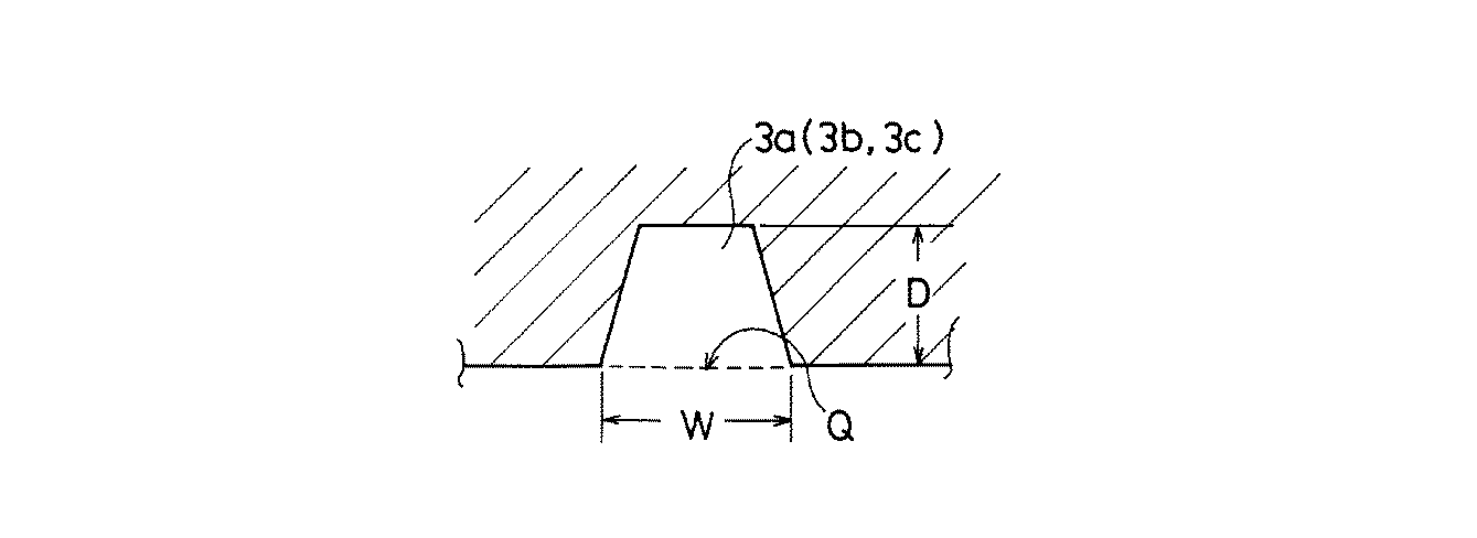
表1から、本発明タイヤは、従来タイヤに比して、新品時から長距離走行後に至るまで車室内における騒音が抑制されていることがわかる。 From Table 1, it can be seen that in the tire of the present invention, noise in the passenger compartment is suppressed from when it is new to after long distance running, compared to the conventional tire.
1 トレッド面
2 周方向溝
3a、3b、3c、3d 横方向溝
4a、4b、4c ブロック
P1 大ピッチ
P2 中ピッチ
P3 小ピッチ
R タイヤ回転方向
1 Tread
Claims (5)
前記横方向溝に面する前記ブロックのタイヤ反回転方向側壁面の傾斜角度αをタイヤ回転方向側壁面の傾斜角度βよりも大きくすると共に、前記ピッチの最大ピッチから最小ピッチまでの単位配列内における前記傾斜角度α及びβを前記ピッチの大きさに応じて大きいピッチほど大きくした空気入りタイヤ。 A large number of blocks are formed on the tread surface by a plurality of circumferential grooves extending in the tire circumferential direction and a plurality of lateral grooves obliquely intersecting the circumferential grooves and arranged at a plurality of different pitches in the tire circumferential direction. In a pneumatic tire that is partitioned and whose rotation direction is specified,
The inclination angle α of the tire anti-rotation side wall surface of the block facing the lateral groove is made larger than the inclination angle β of the tire rotation direction side wall surface, and in the unit array from the maximum pitch to the minimum pitch of the pitch A pneumatic tire in which the inclination angles α and β are increased with increasing pitch according to the size of the pitch.
The pneumatic tire according to claim 1, wherein the inclination angle α is 1.6 to 2.0 times the inclination angle β.
Priority Applications (1)
| Application Number | Priority Date | Filing Date | Title |
|---|---|---|---|
| JP2005300006A JP4857703B2 (en) | 2005-10-14 | 2005-10-14 | Pneumatic tire |
Applications Claiming Priority (1)
| Application Number | Priority Date | Filing Date | Title |
|---|---|---|---|
| JP2005300006A JP4857703B2 (en) | 2005-10-14 | 2005-10-14 | Pneumatic tire |
Publications (2)
| Publication Number | Publication Date |
|---|---|
| JP2007106295A true JP2007106295A (en) | 2007-04-26 |
| JP4857703B2 JP4857703B2 (en) | 2012-01-18 |
Family
ID=38032498
Family Applications (1)
| Application Number | Title | Priority Date | Filing Date |
|---|---|---|---|
| JP2005300006A Expired - Fee Related JP4857703B2 (en) | 2005-10-14 | 2005-10-14 | Pneumatic tire |
Country Status (1)
| Country | Link |
|---|---|
| JP (1) | JP4857703B2 (en) |
Cited By (3)
| Publication number | Priority date | Publication date | Assignee | Title |
|---|---|---|---|---|
| US7975738B2 (en) | 2006-11-24 | 2011-07-12 | The Yokohama Rubber Co., Ltd. | Pneumatic tire with tread having lateral grooves |
| EP3335907A1 (en) * | 2016-12-13 | 2018-06-20 | Continental Reifen Deutschland GmbH | Pneumatic tyre for a vehicle |
| EP3272551A4 (en) * | 2015-03-17 | 2018-09-12 | The Yokohama Rubber Co., Ltd. | Pneumatic tire |
Citations (3)
| Publication number | Priority date | Publication date | Assignee | Title |
|---|---|---|---|---|
| JPH06115319A (en) * | 1992-10-02 | 1994-04-26 | Bridgestone Corp | Pneumatic tire |
| JPH1081114A (en) * | 1996-07-17 | 1998-03-31 | Sumitomo Rubber Ind Ltd | Pneumatic tire |
| JP2004210133A (en) * | 2002-12-27 | 2004-07-29 | Yokohama Rubber Co Ltd:The | Pneumatic tire, method of manufacturing the same, and molding die |
-
2005
- 2005-10-14 JP JP2005300006A patent/JP4857703B2/en not_active Expired - Fee Related
Patent Citations (3)
| Publication number | Priority date | Publication date | Assignee | Title |
|---|---|---|---|---|
| JPH06115319A (en) * | 1992-10-02 | 1994-04-26 | Bridgestone Corp | Pneumatic tire |
| JPH1081114A (en) * | 1996-07-17 | 1998-03-31 | Sumitomo Rubber Ind Ltd | Pneumatic tire |
| JP2004210133A (en) * | 2002-12-27 | 2004-07-29 | Yokohama Rubber Co Ltd:The | Pneumatic tire, method of manufacturing the same, and molding die |
Cited By (4)
| Publication number | Priority date | Publication date | Assignee | Title |
|---|---|---|---|---|
| US7975738B2 (en) | 2006-11-24 | 2011-07-12 | The Yokohama Rubber Co., Ltd. | Pneumatic tire with tread having lateral grooves |
| EP3272551A4 (en) * | 2015-03-17 | 2018-09-12 | The Yokohama Rubber Co., Ltd. | Pneumatic tire |
| US10759231B2 (en) | 2015-03-17 | 2020-09-01 | The Yokohama Rubber Co., Ltd. | Pneumatic tire |
| EP3335907A1 (en) * | 2016-12-13 | 2018-06-20 | Continental Reifen Deutschland GmbH | Pneumatic tyre for a vehicle |
Also Published As
| Publication number | Publication date |
|---|---|
| JP4857703B2 (en) | 2012-01-18 |
Similar Documents
| Publication | Publication Date | Title |
|---|---|---|
| JP3367927B2 (en) | Pneumatic tire | |
| JP4394161B1 (en) | Pneumatic tire | |
| US11135879B2 (en) | Pneumatic tire | |
| US20170120688A1 (en) | Pneumatic Tire | |
| JP6304329B2 (en) | Pneumatic tire | |
| JP2010076561A (en) | Pneumatic tire | |
| JP4964560B2 (en) | Pneumatic tire | |
| JP2010260471A (en) | Pneumatic tire | |
| JP2015224002A (en) | Pneumatic tire | |
| JP2015071347A (en) | Pneumatic tire | |
| JP6241157B2 (en) | Pneumatic tire | |
| JP4350103B2 (en) | Pneumatic tire | |
| CN109070653A (en) | Tire and tire-mold | |
| JP5926765B2 (en) | Pneumatic tire | |
| JP4857703B2 (en) | Pneumatic tire | |
| JP2003054221A (en) | Pneumatic tire | |
| EP3556574B1 (en) | Tire | |
| JP6091872B2 (en) | Pneumatic tire | |
| JP2004299652A (en) | Pneumatic tire | |
| JP2013132993A (en) | Pneumatic tire | |
| JP2004058838A (en) | Pneumatic tire | |
| JPH08142612A (en) | Pneumatic tire | |
| JP5795497B2 (en) | tire | |
| JP2007045233A (en) | Pneumatic tire | |
| JP2008049971A (en) | Pneumatic tire |
Legal Events
| Date | Code | Title | Description |
|---|---|---|---|
| A621 | Written request for application examination |
Free format text: JAPANESE INTERMEDIATE CODE: A621 Effective date: 20080909 |
|
| A131 | Notification of reasons for refusal |
Free format text: JAPANESE INTERMEDIATE CODE: A131 Effective date: 20110125 |
|
| A521 | Written amendment |
Free format text: JAPANESE INTERMEDIATE CODE: A523 Effective date: 20110223 |
|
| A02 | Decision of refusal |
Free format text: JAPANESE INTERMEDIATE CODE: A02 Effective date: 20110412 |
|
| A521 | Written amendment |
Free format text: JAPANESE INTERMEDIATE CODE: A523 Effective date: 20110512 |
|
| A911 | Transfer of reconsideration by examiner before appeal (zenchi) |
Free format text: JAPANESE INTERMEDIATE CODE: A911 Effective date: 20110613 |
|
| TRDD | Decision of grant or rejection written | ||
| A01 | Written decision to grant a patent or to grant a registration (utility model) |
Free format text: JAPANESE INTERMEDIATE CODE: A01 Effective date: 20111004 |
|
| A01 | Written decision to grant a patent or to grant a registration (utility model) |
Free format text: JAPANESE INTERMEDIATE CODE: A01 |
|
| A61 | First payment of annual fees (during grant procedure) |
Free format text: JAPANESE INTERMEDIATE CODE: A61 Effective date: 20111017 |
|
| R150 | Certificate of patent or registration of utility model |
Free format text: JAPANESE INTERMEDIATE CODE: R150 |
|
| FPAY | Renewal fee payment (event date is renewal date of database) |
Free format text: PAYMENT UNTIL: 20141111 Year of fee payment: 3 |
|
| FPAY | Renewal fee payment (event date is renewal date of database) |
Free format text: PAYMENT UNTIL: 20141111 Year of fee payment: 3 |
|
| LAPS | Cancellation because of no payment of annual fees |