JP2007105577A - Equipment for separation of sedimented sand - Google Patents
Equipment for separation of sedimented sand Download PDFInfo
- Publication number
- JP2007105577A JP2007105577A JP2005296816A JP2005296816A JP2007105577A JP 2007105577 A JP2007105577 A JP 2007105577A JP 2005296816 A JP2005296816 A JP 2005296816A JP 2005296816 A JP2005296816 A JP 2005296816A JP 2007105577 A JP2007105577 A JP 2007105577A
- Authority
- JP
- Japan
- Prior art keywords
- sand
- separation
- raw water
- sand settling
- chamber
- Prior art date
- Legal status (The legal status is an assumption and is not a legal conclusion. Google has not performed a legal analysis and makes no representation as to the accuracy of the status listed.)
- Granted
Links
Images


Landscapes
- Separation Of Solids By Using Liquids Or Pneumatic Power (AREA)
Abstract
Description
本発明は、水処理設備を流れる原水中の砂を分離して沈降させ、貯留ホッパへ導く沈砂分離設備に関する。 The present invention relates to a sand settling facility that separates and sinks sand in raw water flowing through a water treatment facility and guides it to a storage hopper.
下水処理場、浄水場または各種工場排水処理場などの水処理設備では、特許文献1に記載のように、原水中に混在した砂を沈降させ分離させる沈砂池と、この沈砂池にて分離された沈砂を原水と共に汲み上げる揚砂装置と、この揚砂装置にて汲み上げられた原水から砂を分離する大容量の分離装置と、この分離された砂を貯留ホッパへ搬送するスクリューコンベヤ装置と、砂を貯留する上記貯留ホッパとが設けられている。
上述のように、従来の水処理設備では、揚砂装置からの原水中の砂を大容量の分離装置にて分離し、分離された砂をスクリューコンベヤ装置を用いて貯留ホッパへ搬送することから、揚砂装置から貯留ホッパまでに大きなスペースが必要になる。従って、例えば地下などの限られたスペースに上記分離装置及びスクリューコンベヤ装置などを配置することは、非常に困難なレイアウトになっている。 As described above, in the conventional water treatment facility, the sand in the raw water from the sand lifting device is separated by a large-capacity separating device, and the separated sand is conveyed to the storage hopper using a screw conveyor device. A large space is required from the sand lifting device to the storage hopper. Therefore, for example, it is very difficult to arrange the separation device and the screw conveyor device in a limited space such as underground.
本発明の目的は、上述の事情を考慮してなされたものであり、原水中の砂を分離し沈降させ集積して貯溜ホッパへ導く設備を一つにまとめて設備のコンパクト化を図り、省スペース化を実現できる沈砂分離設備を提供することにある。 The object of the present invention has been made in consideration of the above-mentioned circumstances, and is intended to make the equipment compact by combining the equipment that separates, settles and accumulates the sand in the raw water and leads it to the storage hopper. The object is to provide a sedimentation facility that can realize space.
請求項1に記載の発明は、原水中の砂を分離する分離装置と、この分離装置にて分離された砂を沈降して集積し、貯留ホッパへ導く沈砂集積装置とがそれぞれ上部、下部に一体に配置され、上記分離装置は、原水の流速を減速させて当該原水中の砂を分離する分離流路と、砂が分離された原水を排水路へ導く排水流路とを有し、上記分離流路の底面に、分離された砂を上記沈砂集積装置へ落下させるスリットが設けられ、上記沈砂集積装置は、上記分離装置の上記スリットから落下した砂を沈降させて堆積する沈砂室と、この沈砂室内において水平面内で回転して、当該沈砂室に堆積した砂をこの沈砂室の排砂口に集積する掻寄装置と、を有して構成されたことを特徴とするものである。 According to the first aspect of the present invention, a separating device that separates the sand in the raw water and a sand settling device that sinks and collects the sand separated by the separating device and guides the sand to the storage hopper are provided at the upper and lower portions, respectively. The separation device has a separation flow path for decelerating the flow rate of the raw water to separate the sand in the raw water, and a drainage flow path for guiding the raw water from which the sand has been separated to the drainage path. A slit for dropping the separated sand to the sand settling device is provided on the bottom surface of the separation channel, and the sand settling device is a sand settling chamber for sinking and depositing the sand dropped from the slit of the separation device, And a scraping device that rotates in a horizontal plane within the sand settling chamber and accumulates sand accumulated in the sand settling chamber at a sand discharge port of the sand settling chamber.
請求項2に記載の発明は、請求項1に記載の発明において、上記分離装置の分離流路が螺旋構造に構成されたことを特徴とするものである。 According to a second aspect of the present invention, in the first aspect of the present invention, the separation flow path of the separation device is configured in a spiral structure.
請求項3に記載の発明は、請求項2に記載の発明において、上記分離装置の分離流路のスリットは、当該分離流路における遠心力作用方向外側の周壁に沿って当該分離流路の底面に螺旋形状に形成され、また、上記分離流路の底面は、上記スリットへ向かって斜め下方に傾斜する傾斜底面として構成されたことを特徴とするものである。 The invention according to claim 3 is the invention according to claim 2, wherein the slit of the separation channel of the separation device is a bottom surface of the separation channel along the outer peripheral wall in the centrifugal force acting direction in the separation channel. In addition, the bottom surface of the separation channel is configured as an inclined bottom surface that is inclined obliquely downward toward the slit.
請求項4に記載の発明は、請求項1乃至3のいずれかに記載の発明において、上記沈砂集積装置の沈砂室に排水弁が、当該沈砂室の排砂口下流側に砂排出弁がそれぞれ設置され、これらの弁は分離装置への原水の供給停止時に開操作されて、上記分離装置及び上記沈砂集積装置内の原水を上記排水弁を経て排水し、上記沈砂室内の砂を上記排砂口及び上記砂排出弁を経て貯留ホッパへ導入し得るよう構成されたことを特徴とするものである。 The invention according to claim 4 is the invention according to any one of claims 1 to 3, wherein a drain valve is provided in the sand settling chamber of the sand settling device, and a sand discharge valve is provided downstream of the sand discharge port of the sand settling chamber. These valves are opened when the supply of raw water to the separator is stopped, the raw water in the separator and the sand settling device is drained through the drain valve, and the sand in the sand settling chamber is drained from the sand. It is configured to be introduced into the storage hopper through the mouth and the sand discharge valve.
請求項5に記載の発明は、請求項1乃至4のいずれかに記載の発明において、一体に配置された上記分離装置と上記沈砂集積装置のうち、沈砂集積装置の排砂室における排砂口の鉛直下方に貯留ホッパが接続されたことを特徴とするものである。 According to a fifth aspect of the present invention, in the invention according to any one of the first to fourth aspects, the sand discharge port in the sand discharge chamber of the sand settling device among the separating device and the sand settling device arranged integrally. A storage hopper is connected to a vertically lower side of the storage.
請求項1または4に記載の発明によれば、分離装置の分離流路内で原水の流速が減速されることから、この分離流路内を流れる原水中の砂に作用する重力によって、原水中の砂を良好に分離できるので、当該分離装置の高さを低減してコンパクト化を達成できる。また、沈砂集積装置の沈砂室に堆積した砂を排砂口に集積する掻寄装置が当該沈砂室内において水平面内で回転することから、当該沈砂集積装置の高さを低減してコンパクト化を達成できる。これらのことから、分離装置と沈砂集積装置を一体化した沈砂分離設備のコンパクト化を達成でき、省スペース化を実現できる。 According to the invention described in claim 1 or 4, since the flow rate of the raw water is reduced in the separation flow path of the separation device, the gravity of the raw water is reduced by the gravity acting on the sand in the raw water flowing in the separation flow path. Therefore, it is possible to reduce the height of the separation device and achieve compactness. In addition, since the scraping device that accumulates the sand accumulated in the sand settling chamber of the sand settling device rotates in the horizontal plane in the sand settling chamber, the height of the sand settling device is reduced to achieve compactness. it can. For these reasons, it is possible to reduce the size of the sand-sediment separation facility in which the separator and the sand-sediment accumulation device are integrated, thereby realizing space saving.
請求項2に記載の発明によれば、分離装置の分離流路が螺旋構造に構成されたことから、この分離流路内を流動する原水中の砂に重力が作用すると共に、遠心力を作用させることもできるので、この砂を原水から更に良好に分離することができる。 According to the second aspect of the present invention, since the separation flow path of the separation device has a spiral structure, gravity acts on the sand in the raw water flowing in the separation flow path, and centrifugal force acts on the sand. This sand can be further separated from the raw water.
請求項3に記載の発明によれば、分離装置の分離流路のスリットが、当該分離流路における遠心力作用方向外側の周壁に沿って当該分離流路の底面に螺旋形状に形成されたことから、この螺旋形状のスリットを通して、分離した砂を沈砂集積装置の沈砂室内へ分散して沈降させ堆積させることができる。 According to the invention described in claim 3, the slit of the separation channel of the separation device is formed in a spiral shape on the bottom surface of the separation channel along the outer peripheral wall of the separation channel in the direction of the centrifugal force acting. Thus, the separated sand can be dispersed and settled and deposited in the sand settling chamber of the sand settling device through this spiral slit.
また、分離流路の底面が、スリットへ向かって斜め下方に傾斜する傾斜底面として構成されたことから、当該分離流路内で分離された砂をスリットへ集中して導くことができる。 Further, since the bottom surface of the separation channel is configured as an inclined bottom surface that is inclined obliquely downward toward the slit, the sand separated in the separation channel can be concentrated and guided to the slit.
請求項5に記載の発明によれば、沈砂集積装置の排砂室における排砂口の鉛直下方に貯留ホッパが接続されたことから、沈砂室に堆積された砂を滞留させることなく円滑に貯留ホッパに導入することができる。 According to the fifth aspect of the present invention, since the storage hopper is connected vertically below the sand discharge port in the sand discharge chamber of the sand settling device, the sand accumulated in the sand settling chamber can be stored smoothly. Can be introduced into the hopper.
以下、本発明を実施するための最良の形態を、図面に基づき説明する。
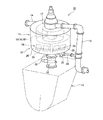
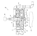
図1は、本発明に係る沈砂分離設備の一実施形態を、貯留ホッパとともに示す斜視図である。図2は、図1の沈砂分離設備を示す縦断面図である。
The best mode for carrying out the present invention will be described below with reference to the drawings.
FIG. 1 is a perspective view showing an embodiment of a sand sedimentation facility according to the present invention together with a storage hopper. FIG. 2 is a longitudinal cross-sectional view showing the sand sedimentation equipment of FIG.
これらの図1及び図2に示すように、沈砂分離設備10は、分離装置11が上部に、沈砂集積装置12が下部に一体に配置されて、一つにまとめられたものである。上記分離装置11は、原水中に混在した砂Pを分離するものであり、また、上記沈砂集積装置12は、分離装置11により分離された砂Pを沈降して集積し貯留ホッパ13へ導くものである。この貯留ホッパ13は、沈砂集積装置12から導入された砂Pを貯留するものであり、沈砂集積装置12の沈砂室25における排砂口31(共に後述)の鉛直下方に、後述の砂排出管32を介して接続されている。
As shown in FIG. 1 and FIG. 2, the sand-
上記分離装置11は、原水搬送管14から供給された原水を水平面内で低速度で流動させながら、その間に原水中に混在する砂Pを分離させる分離流路15と、砂Pが分離された原水をメイン排水管16へ向けてオーバーフローさせて導く排水流路17とを有して構成される。上記分離流路15は、図3に示すように、原水搬送管14に接続されて、この原水搬送管14からの原水を減速させる減速流路18と、この減速流路18に連設されて螺旋構造に構成された螺旋流路19とを備えてなる。
The
上記減速流路18は、流路断面積が原水搬送管14よりも大きく形成されており、原水搬送管14から流入した原水の流速を減速する。また、上記螺旋流路19は、分離装置11の中心方向へ向かって渦巻き形状に形成されており、この中心部分に、沈砂集積装置12に対して開口する排出口20が形成されている。減速流路18にて減速された原水は、螺旋流路19に導入されて渦巻き状に緩やかに流動し、排出口20及び後述のスリット21を経て沈砂集積装置12内へ流入し、オーバーフローして排水流路17を通りにメイン排水管16を経て排水される。
The decelerating
上記スリット21は、螺旋流路19における遠心力作用方向外側の周壁22に沿って、当該螺旋流路19の底板24に螺旋形状に形成され、且つ、減速流路18の底板23にも連続して直線形状に形成される。また、減速流路18の底板23及び螺旋流路19の底板24は、図2に示すように、上記スリット21へ向かって斜め下方へ傾斜する傾斜底板として構成されている。また、これらの減速流路18の底板23及び螺旋流路19の底板24の下方に、分離装置11と沈砂集積装置12とを隔てる隔壁38が設けられている。
The
ここで、図2中の記号A、Bは、螺旋流路19における原水の流れ方向を示し、記号Aは、紙面の奥側から手前側へ向かって原水が流れることを示し、記号Bは、紙面の手前側から奥側へ向かって原水が流れることを示す。また、図3において、分離流路15における原水の流れ方向を矢印Cで示す。
Here, the symbols A and B in FIG. 2 indicate the flow direction of the raw water in the
螺旋流路19内において原水が上述のように緩く渦巻状に流れる間に、流体よりも重い固形分(砂P)が重力の作用で沈降し、更にこの砂Pは、遠心力の作用で螺旋流路19の外側へ押し出される。これらの重力及び遠心力の作用で、原水中の砂Pが原水から分離される。この分離された砂Pは、遠心力の作用と、螺旋流路19における傾斜底板24の斜面及び重力の作用とによって、螺旋流路19の遠心力作用方向外側の周壁22に沿うスリット21内へ集中し、このスリット21から沈砂集積装置12の沈砂室25内へ落下する。このスリット21から沈砂室25内への砂Pの落下は、スリット21の渦巻形状に沿って分散して実施される。
While the raw water flows loosely and spirally in the
上記スリット21から落下できなかった原水中の砂Pは、螺旋流路19の中心部において底板24がなくなるので、この中心部の排出口20から沈砂集積装置12の沈砂室25内へ落下する。
The sand P in the raw water that could not fall from the
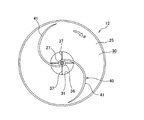
一方、沈砂集積装置12は、分離装置21のスリット21及び排出口20から落下した砂Pを沈降させて、底面30に堆積させる沈砂室25と、この沈砂室25内に配設された複数枚のブレード26を備えた掻寄装置39とを有して構成される。沈砂室25の底面30には、図4にも示すように、中央位置に排砂口31が形成され、この排砂口31に連通して砂排出管32(図2)が接続される。
On the other hand, the
上記砂排出管32は、開閉可能な砂排出弁(例えばバタフライ弁)33を介して貯留ホッパ13に接続される。従って、砂排出弁33は、沈砂室25の排砂口34の下流側に設置される。また、砂排出管32は、砂排出弁33の上流側において、サブ排水管34を介してメイン排水管16に接続され、このサブ排水管34に開閉可能な排水弁35が配設されている。上記砂排出弁33は、開操作時に、沈砂室25内の砂Pを排砂口31、砂排出管32及び当該砂排出弁33を経て貯溜ホッパ13へ導入可能とする。また、上記排水弁35は、開操作時に、分離装置11及び沈砂集積装置12内に貯溜された原水を、サブ排水管34及び当該排水弁35を経てメイン排水管16へ流し排水する。
The
上記掻寄装置39は、図4に示すように、駆動軸27から放射状に延在する複数本の回転アーム28を備え、この回転アーム28に1枚または複数枚のブレード26が取り付けられて構成される。上記駆動軸27は、図2に示すように、分離装置11及び沈砂集積装置12の中央位置において、これらの分離装置11及び沈砂集積装置12を貫通して設置され、駆動モータ29に連結される。従って、駆動モータ29の起動により、駆動軸27を介して回転アーム28が水平面内で回転し、各回転アーム28に取り付けられた1枚または複数枚のブレード26が沈砂室25内において水平面内で回転する。図4の矢印αは、ブレード26の水平面内での回転方向を示す。この水平面内で回転するブレード26が、沈砂室25の底面30に堆積された砂Pを排砂口31へ向かって掻き集める。
As shown in FIG. 4, the
尚、図2及び図4中の符号36は、駆動軸27を軸支する軸受であり、符号37は、この軸受36を支持するステーである。
2 and 4,
駆動モータ29の停止時には、砂排出弁33及び排水弁35を閉状態とする。この状態で沈砂分離設備10内に原水が供給され、分離装置11の螺旋流路19の機能で原水中の砂Pが分離され、この砂Pは、沈砂集積装置12の沈砂室25内に沈降し、その底面30に分散して堆積される。
When the
沈砂分離設備10への原水の供給を停止した後、まず排水弁35を開操作して、分離装置11及び沈砂集積装置12内に貯溜した、砂Pを分離した後の原水をサブ排水管34を経てメイン排水管16へ導き排水する。次に、砂排出弁33を開操作して、この砂排出弁33上流側の砂排出管32内に貯留した砂Pを貯留ホッパ13内へ落下させる。その後、駆動モータ29を起動して掻寄装置39のブレード26を沈砂室25内において水平面内で回転させ、この沈砂室25の底面30に堆積した砂Pを当該底面30の排砂口31へ集積させ、砂排出管32を経て貯留ホッパ13へ導入して、この貯留ホッパ13内に貯留する。
After the supply of raw water to the
以上のように構成されたことから、上記実施の形態によれば、次の効果(1)〜(5)を奏する。
(1)分離装置11の分離流路15(減速流路18及び螺旋流路19)内で原水の流速が減速され、更に螺旋流路19が螺旋構造に構成されたことから、この分離流路15内を流れる原水中の砂Pに作用する重力と遠心力によって、原水中の砂Pを良好に分離できるので、分離装置11の高さH1を低減してコンパクト化を達成できる。また、沈砂集積装置12の沈砂室25に堆積した砂Pを排砂口31に集積する掻寄装置39のブレード26が、沈砂室25内において水平面内で回転することから、沈砂室25内にスクリューコンベヤ等が配設される場合に比べ、当該沈砂集積装置12の高さH2を低減してコンパクト化を達成できる。これらのことから、分離装置11と沈砂集積装置12を一体化した沈砂分離設備10のコンパクト化を達成でき、省スペース化を実現できる。
With the configuration as described above, the following effects (1) to (5) are achieved according to the above embodiment.
(1) Since the flow rate of the raw water is reduced in the separation channel 15 (the
(2)更に、分離装置11の高さH1と沈砂集積装置12の高さH2が共に低減されたことにより、既設の貯留ホッパへの設置が可能となり、関連するベルトコンベアなどの設備を撤去できることから、沈砂分離設備10と上記貯留ホッパを含めたレイアウト構造の自由度を高めることができる。
(2) Furthermore, the height H1 of the
(3)沈砂集積装置12の沈砂室25では、水平面内で回転する掻寄装置39のブレード26を用いることで、この沈砂室25内の底面30に堆積した砂Pを移動させるので、スクリューコンベヤ等で砂Pを移動させる場合に比べ、沈砂室25内における砂の堆積量が少ない状態でも、砂Pを効率的に排砂口31へ移動させることができる。
(3) In the
(4)分離装置11の分離流路15(減速流路18、螺旋流路19)におけるスリット21が、螺旋流路19における遠心力作用方向外側の周壁22に沿って当該螺旋流路19の底板24に螺旋形状に形成され、更に連続して減速流路18の底板23にも形成されたことから、この螺旋形状のスリット21を通して、分離した砂Pを沈砂集積装置の沈砂室25内へ分散して沈降させ堆積させることができ、沈砂室25内への砂Pの堆積量を増大させることができる。
(4) The
(5)減速流路18の底板23及び螺旋流路19の底板24が、スリット21へ向かって斜め下方に傾斜する傾斜底板として構成されたことから、当該分離流路15(減速流路18、螺旋流路19)内で分離された砂Pをスリット21へ集中して導くことができる。
(5) Since the
(6)沈砂集積装置12における沈砂室25の排砂口31の鉛直下方に、砂排出管32を介して貯留ホッパ13が接続されたことから、沈砂室25に堆積された砂Pを滞留させることなく円滑に貯留ホッパ13に導入することができる。
(6) Since the
以上、本発明を上記実施の形態に基づいて説明したが、本発明はこれに限定されるものではない。例えば、上記実施の形態では、沈砂分離設備10の沈砂集積装置12における排砂口31の鉛直下方に、砂排出管32を介して貯留ホッパ13が接続されるものを述べたが、この貯留ホッパ13は、エルボ管またはベンド管などを用いて排砂口31の下方に配置されてもよい。
As mentioned above, although this invention was demonstrated based on the said embodiment, this invention is not limited to this. For example, in the above embodiment, the
また、上記実施の形態において、掻寄装置は、図示した掻寄装置39以外の公知の掻寄装置であってもよい。例えば、図5に示すように、掻寄装置39の回転アーム28及びブレード26に代えて、全体としてS字形状に湾曲した2枚の掻寄部材41を駆動軸27に直接取り付け、これらの掻寄部材41により沈砂室25の底面30に堆積した砂Pを掻き寄せる掻寄装置40であってもよい。
In the above embodiment, the scraping device may be a known scraping device other than the illustrated
10 沈砂分離設備
11 分離装置
12 沈砂集積装置
13 貯留ホッパ
15 分離流路
16 メイン排水管
17 排水流路
18 減速流路
19 螺旋流路
20 排出口
21 スリット
25 沈砂室
26 ブレード
28 回転アーム
31 排砂口
33 砂排出弁
35 排水弁
39 掻寄装置
P 砂
DESCRIPTION OF
Claims (5)
上記分離装置は、原水の流速を減速させて当該原水中の砂を分離する分離流路と、砂が分離された原水を排水路へ導く排水流路とを有し、上記分離流路の底面に、分離された砂を上記沈砂集積装置へ落下させるスリットが設けられ、
上記沈砂集積装置は、上記分離装置の上記スリットから落下した砂を沈降させて堆積する沈砂室と、この沈砂室内において水平面内で回転して、当該沈砂室に堆積した砂をこの沈砂室の排砂口に集積する掻寄装置と、を有して構成されたことを特徴とする沈砂分離設備。 A separation device that separates the sand in the raw water and a sand collection device that sediments and collects the sand separated by this separation device and guides it to the storage hopper are integrally arranged at the upper and lower parts, respectively.
The separation device includes a separation channel that separates sand in the raw water by reducing the flow rate of the raw water, and a drainage channel that guides the raw water from which the sand has been separated to the drainage channel, and the bottom surface of the separation channel Is provided with a slit for dropping the separated sand into the sand settling device,
The sand settling device includes a sand settling chamber in which sand falling from the slit of the separation device is settling and rotating in a horizontal plane in the sand settling chamber, and the sand accumulated in the sand settling chamber is discharged from the sand settling chamber. A sand settling facility characterized by comprising a scraping device that accumulates in a sand mouth.
また、上記分離流路の底面は、上記スリットへ向かって斜め下方に傾斜する傾斜底面として構成されたことを特徴とする請求項2に記載の沈砂分離設備。 The slit of the separation channel of the separation device is formed in a spiral shape on the bottom surface of the separation channel along the outer peripheral wall in the centrifugal force acting direction in the separation channel,
The sand sedimentation equipment according to claim 2, wherein the bottom surface of the separation channel is configured as an inclined bottom surface inclined obliquely downward toward the slit.
これらの弁は分離装置への原水の供給停止時に開操作されて、上記分離装置及び上記沈砂集積装置内の原水を上記排水弁を経て排水し、上記沈砂室内の砂を上記排砂口及び上記砂排出弁を経て貯留ホッパへ導入し得るよう構成されたことを特徴とする請求項1乃至3のいずれかに記載の沈砂分離設備。 A drain valve is installed in the sand settling chamber of the sand settling device, and a sand discharge valve is installed downstream of the sand settling port of the sand settling chamber,
These valves are opened when the supply of raw water to the separator is stopped, the raw water in the separator and the sand settling device is drained through the drain valve, and the sand in the sand settling chamber is drained and the sand outlet The sand-sediment separation facility according to any one of claims 1 to 3, wherein the facility is configured to be introduced into a storage hopper through a sand discharge valve.
Priority Applications (1)
| Application Number | Priority Date | Filing Date | Title |
|---|---|---|---|
| JP2005296816A JP4623653B2 (en) | 2005-10-11 | 2005-10-11 | Sand settling equipment |
Applications Claiming Priority (1)
| Application Number | Priority Date | Filing Date | Title |
|---|---|---|---|
| JP2005296816A JP4623653B2 (en) | 2005-10-11 | 2005-10-11 | Sand settling equipment |
Publications (2)
| Publication Number | Publication Date |
|---|---|
| JP2007105577A true JP2007105577A (en) | 2007-04-26 |
| JP4623653B2 JP4623653B2 (en) | 2011-02-02 |
Family
ID=38031854
Family Applications (1)
| Application Number | Title | Priority Date | Filing Date |
|---|---|---|---|
| JP2005296816A Active JP4623653B2 (en) | 2005-10-11 | 2005-10-11 | Sand settling equipment |
Country Status (1)
| Country | Link |
|---|---|
| JP (1) | JP4623653B2 (en) |
Cited By (4)
| Publication number | Priority date | Publication date | Assignee | Title |
|---|---|---|---|---|
| JP2013238067A (en) * | 2012-05-16 | 2013-11-28 | Taisei Corp | Structure of shallow sump |
| JP2014058822A (en) * | 2012-09-18 | 2014-04-03 | Maezawa Ind Inc | Mud treatment system |
| CN107362915A (en) * | 2016-05-13 | 2017-11-21 | 江苏瑞盛水处理有限公司 | A kind of New-type Swirl Flow desanding device |
| CN113144698A (en) * | 2021-04-20 | 2021-07-23 | 中建环能科技股份有限公司 | Efficient pretreatment system and process for removing sand slag together |
Citations (19)
| Publication number | Priority date | Publication date | Assignee | Title |
|---|---|---|---|---|
| JPS535460A (en) * | 1976-07-05 | 1978-01-19 | Hitachi Metals Ltd | Apparatus for washing sunken sand |
| JPS5355654A (en) * | 1976-10-29 | 1978-05-20 | Hitachi Metals Ltd | Sewage precipitate sand cleaner |
| JPS54149073A (en) * | 1978-05-15 | 1979-11-21 | Kubota Ltd | Sand washer |
| JPS57184406A (en) * | 1981-05-02 | 1982-11-13 | Fukuba Kogyo Kk | Method and apparatus for separating sewage and sand precipitate in sewage treating plant |
| JPS58171205U (en) * | 1982-05-11 | 1983-11-15 | 石川島播磨重工業株式会社 | Sand storage hopper supernatant liquid discharge device |
| JPS6035759U (en) * | 1983-08-12 | 1985-03-12 | 三機工業株式会社 | Sand cleaning equipment |
| JPS61187906A (en) * | 1985-02-15 | 1986-08-21 | Shunji Kato | Precipitation device |
| JPS6249919A (en) * | 1985-08-29 | 1987-03-04 | Tetsuo Nishida | Solid-liquid separator |
| JPH03146147A (en) * | 1989-11-02 | 1991-06-21 | Atsushi Nakazawa | Sand washing and separating machine |
| JPH0647207A (en) * | 1992-07-29 | 1994-02-22 | Mitsubishi Heavy Ind Ltd | Waste water treatment device |
| JP2001025610A (en) * | 1999-07-12 | 2001-01-30 | Hitachi Kiden Kogyo Ltd | Sand separation apparatus |
| JP2002240960A (en) * | 2001-02-13 | 2002-08-28 | Maezawa Ind Inc | Leveling device for material stored in hopper |
| JP2003010898A (en) * | 2001-06-28 | 2003-01-14 | Hitachi Kiden Kogyo Ltd | Draining device of hopper |
| JP2003154208A (en) * | 2001-11-20 | 2003-05-27 | Maezawa Ind Inc | Sedimentary sand separation and storage hopper apparatus |
| JP2004160415A (en) * | 2002-11-15 | 2004-06-10 | Maezawa Ind Inc | Stored material transfer apparatus and solid-liquid separator |
| JP2005211809A (en) * | 2004-01-30 | 2005-08-11 | Hitachi Kiden Kogyo Ltd | Sedimentation separation apparatus |
| JP2005279516A (en) * | 2004-03-30 | 2005-10-13 | Maezawa Ind Inc | Flocculation and precipitation treatment device |
| JP2005305304A (en) * | 2004-04-21 | 2005-11-04 | Maezawa Ind Inc | Apparatus for washing/solid-liquid separation of granular material |
| JP2006095414A (en) * | 2004-09-29 | 2006-04-13 | Hitachi Kiden Kogyo Ltd | Sand separation/washing device |
-
2005
- 2005-10-11 JP JP2005296816A patent/JP4623653B2/en active Active
Patent Citations (19)
| Publication number | Priority date | Publication date | Assignee | Title |
|---|---|---|---|---|
| JPS535460A (en) * | 1976-07-05 | 1978-01-19 | Hitachi Metals Ltd | Apparatus for washing sunken sand |
| JPS5355654A (en) * | 1976-10-29 | 1978-05-20 | Hitachi Metals Ltd | Sewage precipitate sand cleaner |
| JPS54149073A (en) * | 1978-05-15 | 1979-11-21 | Kubota Ltd | Sand washer |
| JPS57184406A (en) * | 1981-05-02 | 1982-11-13 | Fukuba Kogyo Kk | Method and apparatus for separating sewage and sand precipitate in sewage treating plant |
| JPS58171205U (en) * | 1982-05-11 | 1983-11-15 | 石川島播磨重工業株式会社 | Sand storage hopper supernatant liquid discharge device |
| JPS6035759U (en) * | 1983-08-12 | 1985-03-12 | 三機工業株式会社 | Sand cleaning equipment |
| JPS61187906A (en) * | 1985-02-15 | 1986-08-21 | Shunji Kato | Precipitation device |
| JPS6249919A (en) * | 1985-08-29 | 1987-03-04 | Tetsuo Nishida | Solid-liquid separator |
| JPH03146147A (en) * | 1989-11-02 | 1991-06-21 | Atsushi Nakazawa | Sand washing and separating machine |
| JPH0647207A (en) * | 1992-07-29 | 1994-02-22 | Mitsubishi Heavy Ind Ltd | Waste water treatment device |
| JP2001025610A (en) * | 1999-07-12 | 2001-01-30 | Hitachi Kiden Kogyo Ltd | Sand separation apparatus |
| JP2002240960A (en) * | 2001-02-13 | 2002-08-28 | Maezawa Ind Inc | Leveling device for material stored in hopper |
| JP2003010898A (en) * | 2001-06-28 | 2003-01-14 | Hitachi Kiden Kogyo Ltd | Draining device of hopper |
| JP2003154208A (en) * | 2001-11-20 | 2003-05-27 | Maezawa Ind Inc | Sedimentary sand separation and storage hopper apparatus |
| JP2004160415A (en) * | 2002-11-15 | 2004-06-10 | Maezawa Ind Inc | Stored material transfer apparatus and solid-liquid separator |
| JP2005211809A (en) * | 2004-01-30 | 2005-08-11 | Hitachi Kiden Kogyo Ltd | Sedimentation separation apparatus |
| JP2005279516A (en) * | 2004-03-30 | 2005-10-13 | Maezawa Ind Inc | Flocculation and precipitation treatment device |
| JP2005305304A (en) * | 2004-04-21 | 2005-11-04 | Maezawa Ind Inc | Apparatus for washing/solid-liquid separation of granular material |
| JP2006095414A (en) * | 2004-09-29 | 2006-04-13 | Hitachi Kiden Kogyo Ltd | Sand separation/washing device |
Cited By (5)
| Publication number | Priority date | Publication date | Assignee | Title |
|---|---|---|---|---|
| JP2013238067A (en) * | 2012-05-16 | 2013-11-28 | Taisei Corp | Structure of shallow sump |
| JP2014058822A (en) * | 2012-09-18 | 2014-04-03 | Maezawa Ind Inc | Mud treatment system |
| CN107362915A (en) * | 2016-05-13 | 2017-11-21 | 江苏瑞盛水处理有限公司 | A kind of New-type Swirl Flow desanding device |
| CN113144698A (en) * | 2021-04-20 | 2021-07-23 | 中建环能科技股份有限公司 | Efficient pretreatment system and process for removing sand slag together |
| CN113144698B (en) * | 2021-04-20 | 2023-03-31 | 中建环能科技股份有限公司 | Efficient pretreatment system and process for removing sand slag together |
Also Published As
| Publication number | Publication date |
|---|---|
| JP4623653B2 (en) | 2011-02-02 |
Similar Documents
| Publication | Publication Date | Title |
|---|---|---|
| KR101483316B1 (en) | Sand Sedimentation separation apparatus | |
| JP6544559B2 (en) | Solid-liquid separation facility | |
| RU2074929C1 (en) | Method and device for removing silicon particles from sewage | |
| JP4623653B2 (en) | Sand settling equipment | |
| JP5520882B2 (en) | Centrifugal sedimentation device | |
| JP2014014810A (en) | Floating oil separation and recovery systems | |
| KR100832549B1 (en) | Hellix Flow, Multiple Cell Type Waste and Grit Remover | |
| JP2007307489A (en) | Deposited sand separation equipment | |
| KR101230340B1 (en) | Grit and waste treatment | |
| JP2019214048A (en) | Solid-liquid separation system and solid-liquid separation method | |
| JP2006118342A (en) | Oil/water separating device | |
| SE511921C2 (en) | Cutting device | |
| JP2020121293A (en) | Sedimentation basin | |
| CN209952304U (en) | Material sedimentation separator | |
| JP2006198571A (en) | Precipitator | |
| JP4396973B2 (en) | Granular cleaning and solid-liquid separator | |
| WO1990011813A1 (en) | Liquid processing apparatus, its continuous liquid processing apparatus and its continuous liquid processing method | |
| EP2168922B1 (en) | Sewage treatment system | |
| JP2007152243A (en) | Separation and removal apparatus for solid content in liquid | |
| JP3836020B2 (en) | Sediment separation dehydrator | |
| JP2003154210A (en) | Sand collector of sedimentation basin | |
| JP6809724B2 (en) | Solid-liquid separation facility | |
| JP2005288428A (en) | Method for eliminating sludge on split laminar flow partition plate for solid-liquid separation | |
| JPS629931Y2 (en) | ||
| KR100907691B1 (en) | Sludge treatment unit and sedimentation equipment having the same, sludge treatment method using the same |
Legal Events
| Date | Code | Title | Description |
|---|---|---|---|
| A621 | Written request for application examination |
Free format text: JAPANESE INTERMEDIATE CODE: A621 Effective date: 20080728 |
|
| A977 | Report on retrieval |
Free format text: JAPANESE INTERMEDIATE CODE: A971007 Effective date: 20100806 |
|
| A131 | Notification of reasons for refusal |
Free format text: JAPANESE INTERMEDIATE CODE: A131 Effective date: 20100819 |
|
| A521 | Written amendment |
Free format text: JAPANESE INTERMEDIATE CODE: A523 Effective date: 20101013 |
|
| TRDD | Decision of grant or rejection written | ||
| A01 | Written decision to grant a patent or to grant a registration (utility model) |
Free format text: JAPANESE INTERMEDIATE CODE: A01 Effective date: 20101028 |
|
| A01 | Written decision to grant a patent or to grant a registration (utility model) |
Free format text: JAPANESE INTERMEDIATE CODE: A01 |
|
| A61 | First payment of annual fees (during grant procedure) |
Free format text: JAPANESE INTERMEDIATE CODE: A61 Effective date: 20101029 |
|
| R150 | Certificate of patent or registration of utility model |
Ref document number: 4623653 Country of ref document: JP Free format text: JAPANESE INTERMEDIATE CODE: R150 Free format text: JAPANESE INTERMEDIATE CODE: R150 |
|
| FPAY | Renewal fee payment (event date is renewal date of database) |
Free format text: PAYMENT UNTIL: 20131112 Year of fee payment: 3 |