JP2007100697A - Double layer tip cap - Google Patents
Double layer tip cap Download PDFInfo
- Publication number
- JP2007100697A JP2007100697A JP2006270518A JP2006270518A JP2007100697A JP 2007100697 A JP2007100697 A JP 2007100697A JP 2006270518 A JP2006270518 A JP 2006270518A JP 2006270518 A JP2006270518 A JP 2006270518A JP 2007100697 A JP2007100697 A JP 2007100697A
- Authority
- JP
- Japan
- Prior art keywords
- cap
- shield
- tip cap
- tip
- based alloy
- Prior art date
- Legal status (The legal status is an assumption and is not a legal conclusion. Google has not performed a legal analysis and makes no representation as to the accuracy of the status listed.)
- Granted
Links
Images

Classifications
-
- F—MECHANICAL ENGINEERING; LIGHTING; HEATING; WEAPONS; BLASTING
- F01—MACHINES OR ENGINES IN GENERAL; ENGINE PLANTS IN GENERAL; STEAM ENGINES
- F01D—NON-POSITIVE DISPLACEMENT MACHINES OR ENGINES, e.g. STEAM TURBINES
- F01D5/00—Blades; Blade-carrying members; Heating, heat-insulating, cooling or antivibration means on the blades or the members
- F01D5/12—Blades
- F01D5/14—Form or construction
- F01D5/20—Specially-shaped blade tips to seal space between tips and stator
-
- F—MECHANICAL ENGINEERING; LIGHTING; HEATING; WEAPONS; BLASTING
- F05—INDEXING SCHEMES RELATING TO ENGINES OR PUMPS IN VARIOUS SUBCLASSES OF CLASSES F01-F04
- F05D—INDEXING SCHEME FOR ASPECTS RELATING TO NON-POSITIVE-DISPLACEMENT MACHINES OR ENGINES, GAS-TURBINES OR JET-PROPULSION PLANTS
- F05D2230/00—Manufacture
- F05D2230/30—Manufacture with deposition of material
-
- F—MECHANICAL ENGINEERING; LIGHTING; HEATING; WEAPONS; BLASTING
- F05—INDEXING SCHEMES RELATING TO ENGINES OR PUMPS IN VARIOUS SUBCLASSES OF CLASSES F01-F04
- F05D—INDEXING SCHEME FOR ASPECTS RELATING TO NON-POSITIVE-DISPLACEMENT MACHINES OR ENGINES, GAS-TURBINES OR JET-PROPULSION PLANTS
- F05D2230/00—Manufacture
- F05D2230/90—Coating; Surface treatment
-
- F—MECHANICAL ENGINEERING; LIGHTING; HEATING; WEAPONS; BLASTING
- F05—INDEXING SCHEMES RELATING TO ENGINES OR PUMPS IN VARIOUS SUBCLASSES OF CLASSES F01-F04
- F05D—INDEXING SCHEME FOR ASPECTS RELATING TO NON-POSITIVE-DISPLACEMENT MACHINES OR ENGINES, GAS-TURBINES OR JET-PROPULSION PLANTS
- F05D2260/00—Function
- F05D2260/95—Preventing corrosion
Landscapes
- Engineering & Computer Science (AREA)
- Mechanical Engineering (AREA)
- General Engineering & Computer Science (AREA)
- Turbine Rotor Nozzle Sealing (AREA)
- Other Surface Treatments For Metallic Materials (AREA)
Abstract
【課題】タービン動翼(10)に使用される先端キャップ(100)を提供すること。
【解決手段】本先端キャップ(100)は、耐酸化性材料のシールド(110)およびシールド(110)内に配置される高強度材料のキャップ(120)を含むことができる。
【選択図】図2A tip cap (100) for use in a turbine blade (10) is provided.
The tip cap (100) may include an oxidation resistant material shield (110) and a high strength material cap (120) disposed within the shield (110).
[Selection] Figure 2
Description
本発明は、一般に、タービンエンジンに関し、より具体的にはタービン動翼用の二層先端キャップに関する。 The present invention relates generally to turbine engines, and more particularly to a two-layer tip cap for a turbine blade.
ガスタービンエンジンにおいて、空気は圧縮機内で加圧され、次いで燃料と混合されて燃焼器内で点火され、高温燃焼ガスが発生する。ガスは、タービン段を通って流れ、そこからエネルギが取り出されて圧縮機に動力を供給し有用な仕事を行う。タービン段は、支持ロータディスクから外方に延びるタービン動翼の列を含む。各タービン動翼は、燃焼ガスが上を流れるエーロフォイルを含む。エーロフォイルは、全体的に中空であり、それには動作中クーラントとして使用される圧縮機からの抽気がもたらされる。 In a gas turbine engine, air is pressurized in a compressor, then mixed with fuel and ignited in a combustor, generating hot combustion gases. The gas flows through the turbine stage from which energy is extracted to power the compressor and perform useful work. The turbine stage includes a row of turbine blades extending outwardly from the support rotor disk. Each turbine blade includes an airfoil over which combustion gases flow. The airfoil is generally hollow, resulting in bleed from the compressor that is used as coolant during operation.
各タービン動翼は、ブレード本体および先端キャップを含む。先端キャップは、その動作環境から、耐酸化性でなければならない。先端キャップはまた、クリープにより膨れ上がる傾向がある。十分なクリープ強度がある大多数の合金は、酸化に対して十分な耐性がない。十分な耐酸化性がある大多数の合金は、十分なクリープ強度がない。クリープおよび酸化の両方について十分な特性がないそれらの合金は、一般に、特注鋳造ビレット(custom cast billet)を除いて利用することができない。そうした特注鋳造ビレットは、完成品を作るのに多額の費用をかけて加工しなければならない。他の代替方法は、先端キャップの下側にアルミナイズド被膜(alminized coating)を使用することを含む。
したがって、十分な耐酸化性および十分なクリープ強度の両方をもたらす適当な材料の要望がある。好ましくは、材料は、費用および作業性からみて適当であるべきである。 Accordingly, there is a need for a suitable material that provides both sufficient oxidation resistance and sufficient creep strength. Preferably, the material should be appropriate in terms of cost and workability.
したがって、本特許出願では、タービン動翼に使用される先端キャップについて説明する。本先端キャップは、耐酸化性材料のシールドおよびシールド内に配置される高強度材料のキャップを含むことができる。 Therefore, in this patent application, a tip cap used in a turbine rotor blade will be described. The tip cap may include a shield of oxidation resistant material and a cap of high strength material disposed within the shield.
耐酸化性材料は、ニッケル基合金またはコバルト基合金であってよい。シールドの厚さは、約0.025〜約0.762ミリメートル(約0.001〜約0.030インチ)であってよい。高強度材料は、ニッケル基合金またはコバルト基合金であってよい。具体的には、高強度材料は、耐クリープ性の析出強化型超合金(precipitation-strengthened,creep resistant super alloy)を含むことができる。キャップの厚さは、約0.762〜約3ミリメートル(約0.030〜0.120インチ)であってよい。 The oxidation resistant material may be a nickel-based alloy or a cobalt-based alloy. The thickness of the shield may be about 0.025 to about 0.762 millimeters (about 0.001 to about 0.030 inches). The high strength material may be a nickel-based alloy or a cobalt-based alloy. Specifically, the high-strength material can include a creep-resistant precipitation-resistant superalloy. The thickness of the cap may be from about 0.762 to about 3 millimeters (about 0.030 to 0.120 inches).
シールドは、カップ形を有することができ、キャップはシールド内に嵌合する。シールドは、平板であってもよく、キャップはシールドに取り付けられてもよい。シールドは、キャップに被着される粉末であってもよい。シールドは、溶接、ろう付けまたは機械的な取り付けによりキャップに取り付けられてもよい。 The shield can have a cup shape and the cap fits within the shield. The shield may be a flat plate and the cap may be attached to the shield. The shield may be a powder that is applied to the cap. The shield may be attached to the cap by welding, brazing or mechanical attachment.
本特許出願ではさらにタービン動翼について説明する。タービン動翼は、エーロフォイルおよびその内部に配置される先端キャップを含むことができる。先端キャップは、耐酸化性シールドおよび高強度キャップを含むことができる。 This patent application further describes turbine blades. The turbine blade may include an airfoil and a tip cap disposed therein. The tip cap can include an oxidation resistant shield and a high strength cap.
耐酸化性シールドは、ニッケル基合金またはコバルト基合金を含むことができる。耐酸化性シールドの厚さは、約0.025〜約0.762ミリメートル(約0.001〜約0.030インチ)であってよい。高強度キャップは、ニッケル基合金またはコバルト基合金を含むことができる。高強度キャップの厚さは、約0.762〜約3ミリメートル(約0.030〜0.120インチ)であってよい。高強度キャップは、耐クリープ性の析出強化型超合金を含むことができる。 The oxidation resistant shield can include a nickel-based alloy or a cobalt-based alloy. The thickness of the oxidation resistant shield may be from about 0.001 to about 0.030 inches. The high strength cap can include a nickel-based alloy or a cobalt-based alloy. The thickness of the high strength cap may be about 0.762 to about 3 millimeters (about 0.030 to 0.120 inches). The high strength cap can include a creep resistant precipitation strengthened superalloy.
本発明の上記その他の特徴は、図面および添付の特許請求の範囲と併せて、以下の好ましい実施形態の詳細な説明を検討すれば当業者には明らかになるであろう。 These and other features of the present invention will become apparent to those of ordinary skill in the art upon review of the following detailed description of the preferred embodiment in conjunction with the drawings and the appended claims.
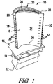
ここで、いくつかの図を通して同じ部品を同じ番号で示す図を参照すると、図1には、タービン動翼10の一実施例が示されている。タービン動翼10は、従来型のダブテール12を含むことができる。ダブテール12は、従来型のロータディスク(図示せず)に取り付けられる。ブレードシャンク14は、ダブテール12から上方に延び、プラットフォーム16で終端する。プラットフォーム16は、シャンク14から外方に突き出しかつそれを囲繞する。
Referring now to the drawings in which like parts are designated by like numerals throughout the several views, one embodiment of a
プラットフォーム16からは中空のエーロフォイル18が外方に延びる。エーロフォイル18は、プラットフォーム16との接合部にルート部20、外端部に先端部22を有する。エーロフォイル18は、凹形圧力側壁24および凸形吸引側壁(convex suction sidewall)26を有し、それらは前縁28および後縁30のところで互いに接合される。エーロフォイル18は、いくつかの後縁冷却孔32およびいくつかの前縁冷却孔33を含むことができる。先端キャップ34は、エーロフォイル18の先端部22を閉鎖することができる。スクイーラ先端部(squealer tip)36は、先端キャップ34から外方に延びることができる。
A
エーロフォイル18の構造は、高温ガス流からエネルギを取り出しロータディスクの回転を発生させるのに適したどんな構造でもよい。本明細書に記載のエーロフォイル18は、単なる一例を挙げたものにすぎない。本特許出願は、このエーロフォイルの実施形態に限定するものではない。エーロフォイル18は、ニューヨーク州スケネクタディ所在のGeneral Electric Corporation製のタービンの1つの動翼段においてまたは同様のタイプの装置において使用されることができる。
The structure of the
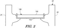
図2には、本明細書で説明される先端キャップ100が示されている。図示のように、先端キャップ100は、エーロフォイル18の側壁24、26の間において先端部22内に配置される。先端キャップ100は、2つの部分からなる構造のものであってよく、シールド110およびキャップ120を含むことができる。
FIG. 2 shows a
シールド110は、酸化シールドである。シールド110は、アルミニウム、珪素、ランタンである添加剤または他の耐酸化性添加剤が加えられたニッケル基合金またはコバルト基合金などの耐酸化性材料で作製されることができる。Haynes230合金などの合金を使用してもよい。シールド110は、シート材、粉末、ワイヤ、めっき材または他のタイプの構成物として作られることができる。シールド110は、平板として、被覆加工材料(cladding material)として使用される、またはカップの形に形成されてもよい。カップの形に形成される場合、カップは別個にされるまたはキャップ120まわりに形成されてもよい。シールドの厚さは、約0.001〜約0.030インチ(約0.025〜約0.762ミリメートル)であってよい。
The
キャップ120は、シート材、鍛造材または鋳造材として作られることができる。キャップ120は、ニッケル基またはコバルト基のガンマプライム強化合金(gamma−prime strengthened alloy)製であってよい。Nimonic263合金材料を使用してもよい。その材料は、高強度および耐食性を有し、優れた成形性を示すことができる。本発明に他のタイプの高強度の材料または構成物を使用してもよい。高強度材料とは、耐性がある材料という意味である。耐クリープ性の析出強化型超合金が好ましい。
The
キャップ120の厚さは、約0.762〜約3ミリメートル(約0.030〜0.120インチ)であってよい。キャップ120は、シールド110内およびエーロフォイル18の動翼先端部22内に嵌合するように寸法設定されることができる。本発明にはどんな所望の寸法も使用することができる。キャップ120は、ワイヤ切断、ウォータージェット切断またはレーザ切断されてよい。キャップ120は、スタンピング、剪断加工またはフライス加工により機械的に切断されてもよい。本発明に他のタイプの製造方法を使用することもできる。
The
図3a〜3eに示されるように、シールド110は、キャップ120の1つの側面(1)、2つの側面(2)、3つの側面(3)または4つすべての側面(4)に取り付けられることができる。シールド110およびキャップ120は、単一の複合先端キャップ100を形成するように一緒に組み立てられ抵抗溶接されることができる。他の形態の溶接またはろう付けを使用してもよい。シールド110は、割れがない溶接を容易するように延性層を形成するようにキャップ120の縁部まわりに延びることができる。先端キャップ100は、側壁24、26に従来のやり方で溶接、ろう付けまたは機械的に取り付けられることができる。さらに、シールド110は、被覆加工作業中に溶加材またはめっき材としてキャップ120に被着されてもよい。シールド110が粉末である場合、キャップ120に直接被着されてよく、または溶接ワイヤの使用、電気めっき、ろう付けの拡散(diffusing a braze perform)もしくはプラズマ溶射により溶接形成(weld built)されてもよい。本発明に他のタイプの製造方法を使用することもできる。
The
したがって、先端キャップ100は、耐酸化性が多少低いが強度が高いキャップ120とともに、多少強度が低く耐酸化性がより高いシールド110を有する。これらの特徴の組み合わせによって、より新しい先端材料を使用する必要がなくなる。この組み合わせによって、修理および/または改修(refurbishment)の費用および時間の両方を低減するために溶接後に先端キャップ100の下側または上側にアルミナイズド被膜を施す必要もなくなる。
Therefore, the
以上の説明は本発明の好ましい実施形態のみに関連し、以下の特許請求の範囲およびその均等物によって定義される本発明の全体的な趣旨および範囲から逸脱することなく、本発明に多くの変更および修正を加えることができると理解されたい。 The foregoing description relates only to the preferred embodiments of the present invention and many modifications are made to the present invention without departing from the general spirit and scope of the invention as defined by the following claims and their equivalents. It should be understood that modifications can be made.
10 タービン動翼
12 ダブテール
14 シャンク
16 プラットフォーム
18 エーロフォイル
20 ルート部
22 先端部
24 圧力側壁
26 吸引側壁
28 前縁
30 後縁
32 後縁冷却孔
33 前縁冷却孔
34、100 先端キャップ
36 スクイーラ先端部
110 シールド
120 キャップ
DESCRIPTION OF
Claims (9)
前記シールド(110)内に配置され、高強度材料を含むキャップ(120)と
を備える、タービン動翼(10)に使用される先端キャップ(100)。 A shield (110) comprising an oxidation resistant material;
A tip cap (100) for use in a turbine blade (10) comprising a cap (120) disposed within the shield (110) and comprising a high strength material.
Applications Claiming Priority (2)
| Application Number | Priority Date | Filing Date | Title |
|---|---|---|---|
| US11/163,067 US7556477B2 (en) | 2005-10-04 | 2005-10-04 | Bi-layer tip cap |
| US11/163,067 | 2005-10-04 |
Publications (3)
| Publication Number | Publication Date |
|---|---|
| JP2007100697A true JP2007100697A (en) | 2007-04-19 |
| JP2007100697A5 JP2007100697A5 (en) | 2009-11-19 |
| JP4998690B2 JP4998690B2 (en) | 2012-08-15 |
Family
ID=37192618
Family Applications (1)
| Application Number | Title | Priority Date | Filing Date |
|---|---|---|---|
| JP2006270518A Expired - Fee Related JP4998690B2 (en) | 2005-10-04 | 2006-10-02 | Double layer tip cap |
Country Status (5)
| Country | Link |
|---|---|
| US (1) | US7556477B2 (en) |
| EP (1) | EP1772593B1 (en) |
| JP (1) | JP4998690B2 (en) |
| CN (1) | CN1978868B (en) |
| CA (1) | CA2561474C (en) |
Cited By (1)
| Publication number | Priority date | Publication date | Assignee | Title |
|---|---|---|---|---|
| JP2015517625A (en) * | 2012-05-09 | 2015-06-22 | シーメンス エナジー インコーポレイテッド | Turbine blade tip repair method |
Families Citing this family (18)
| Publication number | Priority date | Publication date | Assignee | Title |
|---|---|---|---|---|
| DE102008047043A1 (en) * | 2008-09-13 | 2010-03-18 | Mtu Aero Engines Gmbh | A gas turbine blade, gas turbine blade, gas turbine blade replacement, and gas turbine blade repair method |
| US20100200189A1 (en) * | 2009-02-12 | 2010-08-12 | General Electric Company | Method of fabricating turbine airfoils and tip structures therefor |
| US8454310B1 (en) * | 2009-07-21 | 2013-06-04 | Florida Turbine Technologies, Inc. | Compressor blade with tip sealing |
| US8371817B2 (en) * | 2009-09-15 | 2013-02-12 | General Electric Company | Apparatus and method for a turbine bucket tip cap |
| US8734107B2 (en) | 2011-05-31 | 2014-05-27 | General Electric Company | Ceramic-based tip cap for a turbine bucket |
| CH705187A1 (en) * | 2011-06-17 | 2012-12-31 | Alstom Technology Ltd | Cast turbine blade. |
| US8985956B2 (en) | 2011-09-19 | 2015-03-24 | General Electric Company | Compressive stress system for a gas turbine engine |
| US20130236318A1 (en) * | 2012-03-06 | 2013-09-12 | General Electric Company | Fabricated turbine airfoil |
| US9050769B2 (en) * | 2012-04-13 | 2015-06-09 | General Electric Company | Pre-form ceramic matrix composite cavity and method of forming and method of forming a ceramic matrix composite component |
| EP2700788A1 (en) | 2012-08-21 | 2014-02-26 | Alstom Technology Ltd | Vane or blade with tip cap |
| GB201313596D0 (en) * | 2013-07-30 | 2013-09-11 | Composite Technology & Applic Ltd | A tip cap for a fan blade |
| US10569361B2 (en) * | 2013-10-30 | 2020-02-25 | United Technologies Corporation | Laser powder deposition weld rework for gas turbine engine non-fusion weldable nickel castings |
| US20150308449A1 (en) * | 2014-03-11 | 2015-10-29 | United Technologies Corporation | Gas turbine engine component with brazed cover |
| US10202854B2 (en) | 2014-12-18 | 2019-02-12 | Rolls-Royce North America Technologies, Inc. | Abrasive tips for ceramic matrix composite blades and methods for making the same |
| GB201514801D0 (en) * | 2015-08-20 | 2015-10-07 | Rolls Royce Plc And Rolls Royce Deutschland Ltd & Co Kg | Method of manufacture of a turbine component |
| US10677067B2 (en) * | 2016-09-29 | 2020-06-09 | General Electric Company | Airfoil and method of assembling same |
| US11203938B2 (en) | 2018-11-08 | 2021-12-21 | General Electric Company | Airfoil coupon attachment |
| US11143033B2 (en) * | 2018-11-08 | 2021-10-12 | General Electric Company | Turbomachine blade tip attachment |
Citations (8)
| Publication number | Priority date | Publication date | Assignee | Title |
|---|---|---|---|---|
| JPS63212703A (en) * | 1986-12-29 | 1988-09-05 | ユナイテッド・テクノロジーズ・コーポレイション | Turbine blade with molten-metal ceramic abrasive nose section and manufacture thereof |
| JPH06184685A (en) * | 1992-07-23 | 1994-07-05 | Abb Res Ltd | Precipitation hardenable nickel-based superalloy and method of using this alloy as a material in the manufacture of conditioned and solidified structural members |
| US5752802A (en) * | 1996-12-19 | 1998-05-19 | Solar Turbines Incorporated | Sealing apparatus for airfoils of gas turbine engines |
| JPH11350094A (en) * | 1998-06-12 | 1999-12-21 | Hitachi Ltd | Gas turbine blade |
| US20020141869A1 (en) * | 2001-03-27 | 2002-10-03 | Ching-Pang Lee | Turbine blade tip having thermal barrier coating-formed micro cooling channels |
| US20030118445A1 (en) * | 2001-12-20 | 2003-06-26 | Ching-Pang Lee | Foil formed structure for turbine airfoil |
| JP2004332116A (en) * | 2003-05-09 | 2004-11-25 | General Electric Co <Ge> | Nickel-based alloy |
| JP2005248958A (en) * | 2004-03-02 | 2005-09-15 | General Electric Co <Ge> | Gas turbine bucket tip cap |
Family Cites Families (15)
| Publication number | Priority date | Publication date | Assignee | Title |
|---|---|---|---|---|
| US3785809A (en) * | 1971-06-15 | 1974-01-15 | United Aircraft Corp | Nickel-base superalloy |
| US4020538A (en) * | 1973-04-27 | 1977-05-03 | General Electric Company | Turbomachinery blade tip cap configuration |
| US3899267A (en) * | 1973-04-27 | 1975-08-12 | Gen Electric | Turbomachinery blade tip cap configuration |
| US4589824A (en) * | 1977-10-21 | 1986-05-20 | United Technologies Corporation | Rotor blade having a tip cap end closure |
| US4214355A (en) * | 1977-12-21 | 1980-07-29 | General Electric Company | Method for repairing a turbomachinery blade tip |
| GB2028928B (en) * | 1978-08-17 | 1982-08-25 | Ross Royce Ltd | Aerofoil blade for a gas turbine engine |
| US4247254A (en) * | 1978-12-22 | 1981-01-27 | General Electric Company | Turbomachinery blade with improved tip cap |
| US4390320A (en) * | 1980-05-01 | 1983-06-28 | General Electric Company | Tip cap for a rotor blade and method of replacement |
| US4411597A (en) * | 1981-03-20 | 1983-10-25 | The United States Of America As Represented By The Administrator Of The National Aeronautics And Space Administration | Tip cap for a rotor blade |
| US4540339A (en) * | 1984-06-01 | 1985-09-10 | The United States Of America As Represented By The Secretary Of The Air Force | One-piece HPTR blade squealer tip |
| US5359770A (en) * | 1992-09-08 | 1994-11-01 | General Motors Corporation | Method for bonding abrasive blade tips to the tip of a gas turbine blade |
| US6231307B1 (en) | 1999-06-01 | 2001-05-15 | General Electric Company | Impingement cooled airfoil tip |
| US6616410B2 (en) * | 2001-11-01 | 2003-09-09 | General Electric Company | Oxidation resistant and/or abrasion resistant squealer tip and method for casting same |
| US7059834B2 (en) * | 2003-01-24 | 2006-06-13 | United Technologies Corporation | Turbine blade |
| DE10326541A1 (en) * | 2003-06-12 | 2005-01-05 | Mtu Aero Engines Gmbh | A method for blade tip armor of the blades of a gas turbine engine and apparatus for performing the method |
-
2005
- 2005-10-04 US US11/163,067 patent/US7556477B2/en not_active Expired - Fee Related
-
2006
- 2006-09-28 CA CA2561474A patent/CA2561474C/en not_active Expired - Fee Related
- 2006-09-29 EP EP06255037.1A patent/EP1772593B1/en not_active Ceased
- 2006-09-29 CN CN2006101447431A patent/CN1978868B/en not_active Expired - Fee Related
- 2006-10-02 JP JP2006270518A patent/JP4998690B2/en not_active Expired - Fee Related
Patent Citations (8)
| Publication number | Priority date | Publication date | Assignee | Title |
|---|---|---|---|---|
| JPS63212703A (en) * | 1986-12-29 | 1988-09-05 | ユナイテッド・テクノロジーズ・コーポレイション | Turbine blade with molten-metal ceramic abrasive nose section and manufacture thereof |
| JPH06184685A (en) * | 1992-07-23 | 1994-07-05 | Abb Res Ltd | Precipitation hardenable nickel-based superalloy and method of using this alloy as a material in the manufacture of conditioned and solidified structural members |
| US5752802A (en) * | 1996-12-19 | 1998-05-19 | Solar Turbines Incorporated | Sealing apparatus for airfoils of gas turbine engines |
| JPH11350094A (en) * | 1998-06-12 | 1999-12-21 | Hitachi Ltd | Gas turbine blade |
| US20020141869A1 (en) * | 2001-03-27 | 2002-10-03 | Ching-Pang Lee | Turbine blade tip having thermal barrier coating-formed micro cooling channels |
| US20030118445A1 (en) * | 2001-12-20 | 2003-06-26 | Ching-Pang Lee | Foil formed structure for turbine airfoil |
| JP2004332116A (en) * | 2003-05-09 | 2004-11-25 | General Electric Co <Ge> | Nickel-based alloy |
| JP2005248958A (en) * | 2004-03-02 | 2005-09-15 | General Electric Co <Ge> | Gas turbine bucket tip cap |
Cited By (1)
| Publication number | Priority date | Publication date | Assignee | Title |
|---|---|---|---|---|
| JP2015517625A (en) * | 2012-05-09 | 2015-06-22 | シーメンス エナジー インコーポレイテッド | Turbine blade tip repair method |
Also Published As
| Publication number | Publication date |
|---|---|
| EP1772593B1 (en) | 2019-04-10 |
| US7556477B2 (en) | 2009-07-07 |
| CA2561474C (en) | 2014-07-15 |
| CN1978868B (en) | 2011-04-06 |
| CN1978868A (en) | 2007-06-13 |
| US20070077143A1 (en) | 2007-04-05 |
| EP1772593A3 (en) | 2012-11-14 |
| EP1772593A2 (en) | 2007-04-11 |
| JP4998690B2 (en) | 2012-08-15 |
| CA2561474A1 (en) | 2007-04-04 |
Similar Documents
| Publication | Publication Date | Title |
|---|---|---|
| JP4998690B2 (en) | Double layer tip cap | |
| JP6692609B2 (en) | Turbine bucket assembly and turbine system | |
| JP4181793B2 (en) | Turbine airfoil and manufacturing and repair method thereof | |
| US6634860B2 (en) | Foil formed structure for turbine airfoil tip | |
| US7900458B2 (en) | Turbine airfoils with near surface cooling passages and method of making same | |
| CN103084780B (en) | Method for repairing turbine bucket tip | |
| CN1179060C (en) | Cobalt-based alloy and composite wire made of the cobalt-based alloy | |
| EP3115147A1 (en) | Systems and methods for turbine blade repair | |
| JP2005248958A (en) | Gas turbine bucket tip cap | |
| US7731809B2 (en) | Activated diffusion brazing alloys and repair process | |
| US6837687B2 (en) | Foil formed structure for turbine airfoil | |
| JP2006177363A (en) | Repair method for gas turbine blade tip without recoating of repair blade tip | |
| EP3848142B1 (en) | Superalloy part and method of processing | |
| US6838190B2 (en) | Article with intermediate layer and protective layer, and its fabrication | |
| JP2016000994A (en) | Turbine bucket assembly and turbine system | |
| JP2017115859A (en) | Systems and methods for deep tip crack repair | |
| JP2005201242A (en) | How to repair a gas turbine rotor blade | |
| JP2015224636A (en) | Turbine bucket assembly and turbine system | |
| JP2006348938A (en) | Turbine bucket tip cap | |
| JP2012087787A (en) | Bonded turbine bucket tip shroud and related method | |
| US20200392854A1 (en) | Airfoil with cover for gas turbine engine | |
| JP2015224631A (en) | Turbine bucket assembly and turbine system | |
| US11939879B2 (en) | Blade repair method, blade, and gas turbine | |
| JP2010106833A (en) | Hybrid turbine blade | |
| EP2412930A2 (en) | Turbine nozzle segment and method of repairing same |
Legal Events
| Date | Code | Title | Description |
|---|---|---|---|
| A521 | Request for written amendment filed |
Free format text: JAPANESE INTERMEDIATE CODE: A523 Effective date: 20091002 |
|
| A621 | Written request for application examination |
Free format text: JAPANESE INTERMEDIATE CODE: A621 Effective date: 20091002 |
|
| RD02 | Notification of acceptance of power of attorney |
Free format text: JAPANESE INTERMEDIATE CODE: A7422 Effective date: 20091002 |
|
| RD04 | Notification of resignation of power of attorney |
Free format text: JAPANESE INTERMEDIATE CODE: A7424 Effective date: 20091002 |
|
| A072 | Dismissal of procedure [no reply to invitation to correct request for examination] |
Free format text: JAPANESE INTERMEDIATE CODE: A072 Effective date: 20100126 |
|
| A521 | Request for written amendment filed |
Free format text: JAPANESE INTERMEDIATE CODE: A523 Effective date: 20100924 |
|
| A977 | Report on retrieval |
Free format text: JAPANESE INTERMEDIATE CODE: A971007 Effective date: 20110413 |
|
| A131 | Notification of reasons for refusal |
Free format text: JAPANESE INTERMEDIATE CODE: A131 Effective date: 20110419 |
|
| A601 | Written request for extension of time |
Free format text: JAPANESE INTERMEDIATE CODE: A601 Effective date: 20110719 |
|
| A602 | Written permission of extension of time |
Free format text: JAPANESE INTERMEDIATE CODE: A602 Effective date: 20110829 |
|
| A521 | Request for written amendment filed |
Free format text: JAPANESE INTERMEDIATE CODE: A523 Effective date: 20111013 |
|
| A131 | Notification of reasons for refusal |
Free format text: JAPANESE INTERMEDIATE CODE: A131 Effective date: 20120207 |
|
| A521 | Request for written amendment filed |
Free format text: JAPANESE INTERMEDIATE CODE: A523 Effective date: 20120313 |
|
| TRDD | Decision of grant or rejection written | ||
| A01 | Written decision to grant a patent or to grant a registration (utility model) |
Free format text: JAPANESE INTERMEDIATE CODE: A01 Effective date: 20120403 |
|
| A01 | Written decision to grant a patent or to grant a registration (utility model) |
Free format text: JAPANESE INTERMEDIATE CODE: A01 |
|
| A61 | First payment of annual fees (during grant procedure) |
Free format text: JAPANESE INTERMEDIATE CODE: A61 Effective date: 20120501 |
|
| R150 | Certificate of patent or registration of utility model |
Ref document number: 4998690 Country of ref document: JP Free format text: JAPANESE INTERMEDIATE CODE: R150 Free format text: JAPANESE INTERMEDIATE CODE: R150 |
|
| FPAY | Renewal fee payment (event date is renewal date of database) |
Free format text: PAYMENT UNTIL: 20150525 Year of fee payment: 3 |
|
| R250 | Receipt of annual fees |
Free format text: JAPANESE INTERMEDIATE CODE: R250 |
|
| R250 | Receipt of annual fees |
Free format text: JAPANESE INTERMEDIATE CODE: R250 |
|
| R250 | Receipt of annual fees |
Free format text: JAPANESE INTERMEDIATE CODE: R250 |
|
| R250 | Receipt of annual fees |
Free format text: JAPANESE INTERMEDIATE CODE: R250 |
|
| R250 | Receipt of annual fees |
Free format text: JAPANESE INTERMEDIATE CODE: R250 |
|
| R250 | Receipt of annual fees |
Free format text: JAPANESE INTERMEDIATE CODE: R250 |
|
| LAPS | Cancellation because of no payment of annual fees |