JP2007060026A - Video processing apparatus and object particularizing method - Google Patents
Video processing apparatus and object particularizing method Download PDFInfo
- Publication number
- JP2007060026A JP2007060026A JP2005240197A JP2005240197A JP2007060026A JP 2007060026 A JP2007060026 A JP 2007060026A JP 2005240197 A JP2005240197 A JP 2005240197A JP 2005240197 A JP2005240197 A JP 2005240197A JP 2007060026 A JP2007060026 A JP 2007060026A
- Authority
- JP
- Japan
- Prior art keywords
- video
- display
- specified
- specifying
- processing apparatus
- Prior art date
- Legal status (The legal status is an assumption and is not a legal conclusion. Google has not performed a legal analysis and makes no representation as to the accuracy of the status listed.)
- Pending
Links
Images


Classifications
-
- H—ELECTRICITY
- H04—ELECTRIC COMMUNICATION TECHNIQUE
- H04N—PICTORIAL COMMUNICATION, e.g. TELEVISION
- H04N7/00—Television systems
- H04N7/14—Systems for two-way working
- H04N7/141—Systems for two-way working between two video terminals, e.g. videophone
- H04N7/147—Communication arrangements, e.g. identifying the communication as a video-communication, intermediate storage of the signals
-
- G—PHYSICS
- G06—COMPUTING; CALCULATING OR COUNTING
- G06Q—INFORMATION AND COMMUNICATION TECHNOLOGY [ICT] SPECIALLY ADAPTED FOR ADMINISTRATIVE, COMMERCIAL, FINANCIAL, MANAGERIAL OR SUPERVISORY PURPOSES; SYSTEMS OR METHODS SPECIALLY ADAPTED FOR ADMINISTRATIVE, COMMERCIAL, FINANCIAL, MANAGERIAL OR SUPERVISORY PURPOSES, NOT OTHERWISE PROVIDED FOR
- G06Q10/00—Administration; Management
- G06Q10/10—Office automation; Time management
-
- H—ELECTRICITY
- H04—ELECTRIC COMMUNICATION TECHNIQUE
- H04N—PICTORIAL COMMUNICATION, e.g. TELEVISION
- H04N7/00—Television systems
- H04N7/14—Systems for two-way working
- H04N7/15—Conference systems
Abstract
Description
本発明は、機器で行われたオブジェクトの所定の動作を撮影装置で撮影し、映像データとして記録した後、該映像データを再生する技術に関する。 The present invention relates to a technique for photographing a predetermined operation of an object performed by a device with a photographing device, recording the image as video data, and reproducing the video data.
近年、職場や会議室等で、ディスプレイやプリンタ等のオフィス機器を用いて行われた作業内容や会議内容をカメラで撮影し、撮影された映像を作業記録や会議記録として利用する必要性が高まってきている。その場合、特に撮影された映像から対象オブジェクトを特定することで、長時間の映像中からの検索や利用等の利便性を向上させることが求められており、そのための技術が各種提案されている(例えば、特許文献1〜5)。
In recent years, there has been an increasing need to shoot work content and conference content performed using office equipment such as displays and printers in the workplace and conference rooms with cameras, and use the captured images as work records and conference records. It is coming. In that case, it is required to improve the convenience of searching and using from a long-time video by specifying the target object from the captured video, and various techniques for that are proposed. (For example,
例えば、特許文献1は、撮影された会議映像中から特定の参加者の発言を検索することを目的としたものであり、参加者映像の特定を参加者自身が行うようにしたことで、自動認識による誤認識や担当者による手動設定の煩雑さを回避できるものである。
For example,
また、特許文献2は、通常のホワイトボードから再利用可能な描画オブジェクトを抽出することを目的としたものであり、撮影映像中のホワイトボードのキャプチャデータから描かれた描画オブジェクトを抽出している。これにより、時間軸で連携される音声データと関連付けることができるものである。 Patent Document 2 aims to extract a reusable drawing object from a normal whiteboard, and extracts a drawing object drawn from captured whiteboard data in a captured video. . Thereby, it can associate with the audio | voice data linked | linked on a time axis.
また、特許文献3は、多地点で行われるテレビ会議の議事録を、情報の発信元を判別可能な形式で作成することを目的としたものであり、情報の発信場所と発信順序を示すことができるものである。
また、特許文献4は、複数台のカメラで撮影されたライブ映像と撮影しているカメラを対応付けることで、指定された領域の映像の拡大操作を撮影されたカメラを意識することなく、行えるようにしたものである。 Further, in Patent Document 4, by associating live video captured by a plurality of cameras with a captured camera, it is possible to perform an operation for enlarging a video in a specified area without being aware of the captured camera. It is a thing.
また、特許文献5は、機器を認識するカメラを用いて、ライブ映像中の機器にデータを転送したり、逆に機器からデータを転送したりできるようにしたものである。
しかしながら、特許文献1では、参加者映像の特定方法だけが開示されており、機器及び機器内オブジェクトの特定方法については着目されていない。そのため、例えばディスプレイ上の表示オブジェクトやプリンタ出力トレイ上の印刷オブジェクトを特定することはできない。
However,
また、特許文献2では、通常のホワイトボードだけを対象としており、機器及び機器内オブジェクトの特定方法については着目されていない。そのため、特許文献2も、例えばディスプレイ上の表示オブジェクトやプリンタ出力トレイ上の印刷オブジェクトを特定することはできない。 Further, in Patent Document 2, only a normal whiteboard is targeted, and attention is not paid to a device and a method for identifying an object in the device. Therefore, Patent Document 2 cannot specify, for example, a display object on a display or a print object on a printer output tray.
更に、特許文献3では、生成された議事録中のオブジェクトを特定する方法については開示されていない。そのため、特許文献3も、例えばディスプレイ上の表示オブジェクトやプリンタ出力トレイ上の印刷オブジェクトを特定することはできない。
Furthermore,
更に、特許文献4では、ライブ映像と撮影しているカメラを対応付けているだけで、映像中の機器及び機器内オブジェクトの特定方法については着目されていない。そのため、特許文献4も、例えばディスプレイ上の表示オブジェクトやプリンタ出力トレイ上の印刷オブジェクトを特定することはできない。 Furthermore, Patent Document 4 merely associates a live video with a camera that is shooting, and does not pay attention to a method for specifying a device and an object in the device in the video. For this reason, Patent Document 4 cannot specify, for example, a display object on a display or a print object on a printer output tray.
そして、特許文献5では、カメラが認識するのは映像中の機器だけであり、機器内オブジェクトの特定方法については着目されていない。更に、映像中の機器の認識に関しても具体的な実現方法があいまいである。そのため、特許文献5も、例えばディスプレイ上の表示オブジェクトやプリンタ出力トレイ上の印刷オブジェクトを特定することはできない。 In Patent Document 5, the camera recognizes only the device in the video, and does not pay attention to the method for identifying the in-device object. Furthermore, the specific implementation method is ambiguous also about the recognition of the apparatus in an image | video. Therefore, Patent Document 5 cannot specify a display object on a display or a print object on a printer output tray, for example.
本発明は上記課題を解決するためになされたものであり、機器及び機器内オブジェクトを再生映像中から特定することで、例えばディスプレイ上の表示オブジェクトやプリンタ出力トレイ上の印刷オブジェクトを特定できるようにすることを目的とする。 The present invention has been made to solve the above problems, and by specifying the device and the object in the device from the playback video, for example, the display object on the display and the print object on the printer output tray can be specified. The purpose is to do.
また、特定されたオブジェクトに対する拡大表示や印刷などの所定の操作を可能とすることを目的とする。 It is another object of the present invention to enable a predetermined operation such as enlargement display or printing for a specified object.
本発明は、機器で行われたオブジェクトの所定の動作を撮影装置で撮影し、映像データとして記録した後、該映像データを再生する映像処理装置であって、前記映像データを再生中に所望のオブジェクトが指定された場合に、該オブジェクトの機器内の位置及び動作時刻に関する情報に基づいて前記オブジェクトを特定する特定手段と、前記特定されたオブジェクトに対して所定の操作を実行可能とする操作手段とを有することを特徴とする。 The present invention is a video processing apparatus that captures a predetermined motion of an object performed by a device with a photographing device, records the image as video data, and then reproduces the video data. When an object is specified, a specifying unit that specifies the object based on information on a position of the object in the device and an operation time, and an operation unit that can execute a predetermined operation on the specified object It is characterized by having.
また、本発明は、機器で行われたオブジェクトの所定の動作を撮影装置で撮影し、映像データとして記録した後、該映像データを再生する映像処理装置のオブジェクト特定方法であって、前記映像データを再生中に所望のオブジェクトが指定された場合に、該オブジェクトの機器内の位置及び動作時刻に関する情報に基づいて前記オブジェクトを特定する特定工程と、前記特定されたオブジェクトに対して所定の操作を実行可能とする操作工程とを有することを特徴とする。 The present invention also provides an object specifying method for a video processing apparatus, wherein a predetermined operation of an object performed by a device is shot by a shooting device, recorded as video data, and then played back, and the video data is reproduced. When a desired object is specified during playback, a specifying step of specifying the object based on information on the position of the object in the device and the operation time, and a predetermined operation on the specified object And an operation step that can be executed.
本発明によれば、機器及び機器内オブジェクトを再生映像中から特定することで、例えばディスプレイ上の表示オブジェクトやプリンタ出力トレイ上の印刷オブジェクトを特定することができる。 According to the present invention, it is possible to specify, for example, a display object on a display or a print object on a printer output tray by specifying a device and an object in the device from the reproduced video.
また、特定されたオブジェクトに対する拡大表示や印刷などの操作が可能となる。 In addition, operations such as enlargement display and printing can be performed on the specified object.
以下、図面を参照しながら発明を実施するための最良の形態について詳細に説明する。 The best mode for carrying out the invention will be described below in detail with reference to the drawings.
図1は、実施形態における情報処理装置のハードウェア構成を示すブロック図である。図1において、101は情報(データ)を入力するための入力部であり、例えば後述する撮影装置等が接続される。102はCPUであり、各種処理のための演算や論理判断等を行い、後述するバスに接続された各構成要素を制御する。103は情報(データ)を出力する出力部であり、例えば後述するLCDやCRT等のディスプレイやプリンタ等の画像形成装置が接続される。
FIG. 1 is a block diagram illustrating a hardware configuration of the information processing apparatus according to the embodiment. In FIG. 1,
104はプログラムメモリであり、後述するフローチャートで示される処理手順を含み、CPU102による制御のためのプログラムを格納するメモリである。このプログラムメモリ104は、ROMであっても良いし、また外部記憶装置等からプログラムがロードされるRAMであっても良い。105はデータメモリであり、各種処理で生じたデータを格納する。このデータメモリ105は、例えばRAMとするが、不揮発性の外部記憶媒体から、処理に先立ってロードしておくか、或いは必要がある毎に参照するものとする。
そして、106はCPU102の制御の対象とする各構成要素を指示するアドレス信号、各構成要素を制御するためのコントロール信号、及び各構成要素間で相互に授受されるデータの転送を行うためのバスである。
[第1の実施形態]
ここで、図2〜図18を用いて、再生映像中から指示された時間的位置及び空間的位置に対応する機器及び機器内オブジェクトを特定し、拡大表示や印刷等の操作を行う場合について説明する。第1の実施形態では、特に対象機器がディスプレイであり、その映像がカメラの配置やレンズの特性による歪で、実際のディスプレイの形状(アスペクト比等)が維持されない場合を例に挙げて説明する。
[First Embodiment]
Here, with reference to FIGS. 2 to 18, description will be given of a case where a device and an object in the device corresponding to a temporal position and a spatial position instructed from the reproduced video are specified and an operation such as enlargement display or printing is performed. To do. In the first embodiment, a case will be described as an example where the target device is a display, and the image is distorted due to camera arrangement and lens characteristics, and the actual display shape (aspect ratio, etc.) is not maintained. .
図2は、第1の実施形態におけるシステムイメージの一例を示す図である。図2に示すシステムは会議室をイメージしており、通常の会議室に存在する会議机の他に、大画面のディスプレイ202が3台と、会議の様子を広角で撮影する会議映像撮影カメラ(以下、単にカメラと称す)201とを含む。また、各ディスプレイ202画面上には複数の表示オブジェクト203が表示されている様子が示されている。
FIG. 2 is a diagram illustrating an example of a system image according to the first embodiment. The system shown in FIG. 2 is an image of a conference room. In addition to a conference desk existing in a normal conference room, there are three large-
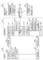
図3は、図2に示すシステムイメージを実現する場合の構成を示すシステムブロック図である。図3に示すように、表示装置301〜303に表示された各表示オブジェクトに関する情報は会議記録装置305によってオブジェクト動作記録データ306として記録される。また、撮影装置304によって撮影された映像も、各表示オブジェクトに関する情報と同様に、撮影映像データ307として記録される。
FIG. 3 is a system block diagram showing a configuration for realizing the system image shown in FIG. As shown in FIG. 3, information regarding each display object displayed on the
このようにして記録されたオブジェクト動作記録データ306、撮影映像データ307は、各機器の撮影映像中での位置や形状を記録した機器位置形状データ308を参照して会議記録再生装置309によって再生される。
The object
尚、第1の実施形態では、図1に示した情報処理装置が図3に示す会議記録装置305及び会議記録再生装置309として機能し、詳細は後述する機器位置形状自動設定や機器位置形状指示を行う機能を有するものである。
In the first embodiment, the information processing apparatus shown in FIG. 1 functions as the
図4は、図3に示す会議記録装置305及び会議記録再生装置309の機能を示す機能ブロック図である。図4に示すように、会議記録400(会議記録装置305に相当)、会議記録再生410(会議記録再生部309に相当)、機器位置形状自動設定430、及び機器位置形状指示440の各機能で構成される。会議記録400は、会議の内容を記録する機能を提供する。会議記録再生410は、記録された会議記録を再生する機能を提供する。機器位置形状自動設定430は、映像変化を伴う動作を機器に実行させて機器位置形状を推測する機能を提供する。そして、機器位置形状指示440は、再生映像中から機器内のオブジェクトを特定するために必要な機器位置形状を指示する機能を提供する。
FIG. 4 is a functional block diagram showing functions of the
会議記録400は、映像撮影部401と、会議操作部402と、オブジェクト表示部403と、オブジェクト動作記録部404とから構成されている。映像撮影部401は、撮影装置304で撮影した会議の様子を撮影映像データ307として記録する。会議操作部402は、会議資料の表示指示や電子ホワイトボードへの書き込み指示を行う。オブジェクト表示部403は、指示に従って表示オブジェクトを表示する。オブジェクト動作記録部404は、表示オブジェクトに対して行われた動作をオブジェクト動作記録データ308として記録する。
The
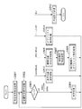
次に、会議記録再生410の構成について説明する。尚、詳細については、更に後述する。会議映像再生部411は、上述の撮影映像データ307として記録された会議映像を再生する。会議映像操作部412は、再生中の映像を操作する。映像位置指定部413は、映像中の任意の位置を指定する。機器位置形状取得部414は、予め定義されている機器位置形状データ308を用いて機器位置形状を取得する。指定機器特定部415は、指定位置の機器を特定する。指定機器内オブジェクト特定部416は、指定位置の機器内オブジェクトを特定する。オブジェクト位置形状取得部417は、特定されたオブジェクトの位置形状を取得する。ディスプレイ内相対位置特定部418は、指定位置に対応するディスプレイ内の相対位置を特定する。オブジェクト動作検索部419は、指定位置に対応するオブジェクト動作を検索する。オブジェクト操作部420は、特定されたオブジェクトを操作する。
Next, the configuration of the conference recording /
機器位置形状自動設定430は、映像変化を伴う動作を機器に実行させる機器位置形状取得可能動作実行部431と、映像変化を解析して機器位置形状を推測して機器位置形状データ308の定義を自動設定する機器位置形状推測部432とから構成されている。機器位置形状指示部441は、機器位置形状データ308の定義を指示する。
The device position shape
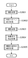
図5は、第1の実施形態における会議記録処理を示すフローチャートである。会議記録400に撮影開始が指示されると、ステップS501において、撮影映像データ307の記録を開始する(映像撮影開始処理)。そして、ステップS502において、ユーザによる操作を受け付け(会議操作処理)、次のステップS503で、オブジェクト操作指示と判定した場合はステップS504へ進み、対応するオブジェクトを表示更新する(オブジェクト表示更新処理)。そして、ステップS505において、その表示更新動作をオブジェクト動作記録データ306として記録し(オブジェクト動作記録処理)、ステップS502に戻り、上述した処理を繰り返す。また、ステップS503において、終了指示と判定した場合はステップS506へ進み、撮影を終了し(映像撮影終了処理)、この会議記録処理を終了する。
FIG. 5 is a flowchart showing the conference recording process in the first embodiment. When the
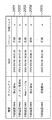
図6は、オブジェクト動作記録データ306の一例を示す図である。図6に示すように、オブジェクト動作記録データ306には、機器、機器内のオブジェクト、オブジェクトが動作した時刻、動作種別(アクション)、表示領域(X1,Y1,X2,Y2)を特定するための情報が記録されている。
FIG. 6 is a diagram illustrating an example of the object
例えば、表示装置301で静止画1aが時刻(2005/05/09 10:35:12)に表示領域((20,50),(450,100))に表示されたことがオブジェクト動作記録データ601として記録されている。その後、静止画1aが非表示にされたことがオブジェクト動作記録データ604として記録されている。
For example, the fact that the
図7は、第1の実施形態におけるオブジェクト動作記録処理を示すフローチャートである。まず、ステップS701において、オブジェクト動作記録データ306からオブジェクトの動作種別を取得する(アクション取得処理)。そして、ステップS702において、動作種別を判定し、動作種別が「表示」又は「移動完了」の場合はステップS703へ進み、ディスプレイ内におけるオブジェクトの表示領域を取得する(ディスプレイ内座標取得処理)。 FIG. 7 is a flowchart showing the object action recording process in the first embodiment. First, in step S701, an object action type is acquired from the object action record data 306 (action acquisition process). In step S702, the action type is determined. If the action type is “display” or “movement completed”, the process advances to step S703 to acquire the display area of the object in the display (intra-display coordinate acquisition process).
また、ステップS702において、動作種別が「非表示」の場合はステップS704へ進み、各表示装置上での操作時刻からシステムの絶対時刻を取得する(絶対時刻取得処理)。次に、ステップS705において、この処理で取得した情報をオブジェクト動作記録データ306として記録し(記録処理)、この処理を終了する。一方、ステップS702において、動作種別が上記以外の場合には、ステップS703以降の処理を行わずに、この処理を終了する。 If the operation type is “non-display” in step S702, the process proceeds to step S704, and the absolute time of the system is acquired from the operation time on each display device (absolute time acquisition process). Next, in step S705, the information acquired in this process is recorded as object action record data 306 (recording process), and this process ends. On the other hand, if the action type is other than the above in step S702, the process is terminated without performing the processes after step S703.
図8は、第1の実施形態における会議記録再生処理を示すフローチャートである。まず、ステップS801において、会議記録再生410に操作対象となる会議記録が指定されると(再生映像指定処理)、続くステップS802で、操作が行われるのを待つ(会議映像操作処理)。ここで、操作が行われると、ステップS803において、その操作が、「再生」、「一時停止からの再開」、「逆再生」指示の何れかの場合はステップS804へ進む。このステップS804では、指定位置からの再生又は逆再生を行い(再生処理)、ステップS802に戻り、上述の処理を繰り返す。 FIG. 8 is a flowchart showing conference recording / playback processing in the first embodiment. First, in step S801, when a conference record to be operated is designated in the conference recording / playback 410 (playback video designation processing), the next step S802 waits for an operation (conference video manipulation processing). When an operation is performed, in step S803, if the operation is any one of “reproduction”, “resume from pause”, and “reverse reproduction” instructions, the process proceeds to step S804. In step S804, reproduction from the designated position or reverse reproduction is performed (reproduction processing), the process returns to step S802, and the above-described processing is repeated.
また、ステップS803において、その操作が「再生位置変更」指示の場合はステップS805へ進み、指定された位置に再生位置を変更し(再生位置変更処理)、ステップS802に戻り、上述の処理を繰り返す。 If it is determined in step S803 that the operation is a “change playback position” instruction, the process advances to step S805 to change the playback position to the designated position (playback position change process), return to step S802, and repeat the above-described process. .
また、ステップS803において、その操作が「映像位置指定」指示の場合はステップS806へ進み、再生位置に対応する時刻の機器位置形状データを取得する(機器位置形状取得処理)。そして、ステップS807において、指定位置に対応する機器を特定する(指定機器特定処理)。次に、ステップS808において、オブジェクト動作記録データ306を参照することで指定位置に対応する機器内オブジェクトを特定する(指定機器内オブジェクト特定処理)。そして、ステップS802に戻り、上述の処理を繰り返す。 In step S803, if the operation is a "video position designation" instruction, the process advances to step S806 to acquire device position shape data at a time corresponding to the reproduction position (device position shape acquisition process). In step S807, the device corresponding to the specified position is specified (specified device specifying process). Next, in step S808, the in-device object corresponding to the specified position is specified by referring to the object action record data 306 (specified in-device object specifying process). And it returns to step S802 and repeats the above-mentioned process.
また、ステップS803において、その操作が「オブジェクト操作」指示の場合はステップS809へ進み、上記手順で特定されたオブジェクトに対する指定された操作を実行する(オブジェクト操作処理)。そして、ステップS802に戻り、上述の処理を繰り返す。また、ステップS803において、その操作が「終了」の場合はステップS810へ進み、再生を終了し(再生終了処理)、この処理を終了する。 If it is determined in step S803 that the operation is an “object operation” instruction, the process advances to step S809 to execute the specified operation on the object specified in the above procedure (object operation processing). And it returns to step S802 and repeats the above-mentioned process. If the operation is “end” in step S803, the process proceeds to step S810 to end reproduction (reproduction end process), and this process ends.
図9は、会議映像の再生操作、再生映像中の指定位置に表示されているオブジェクトを操作可能な会議映像操作画面の一例を示す図である。この例では、再生位置がスクロールバー902上で位置903として示され、対応する時刻の映像901が表示されている。また、再生映像に対する先頭移動904、逆再生905、再生906、末尾移動907、停止908、一時停止909等の指示ボタンが示されている。
FIG. 9 is a diagram illustrating an example of a conference video operation screen in which a conference video playback operation and an object displayed at a specified position in the playback video can be operated. In this example, the playback position is indicated as a
一方、再生映像のオブジェクトに対する操作は、まず再生映像901中の任意の位置が指定911され、その指定位置に対応するオブジェクト操作メニュー912を表示させることにより操作が行われる。
On the other hand, the operation on the object of the playback video is performed by first specifying an
図10は、第1の実施形態における会議映像操作処理を示すフローチャートである。まず、ステップS1001において、行われた操作を判定する。その結果、行われた操作がスクロールバー902上での位置903の変更や先頭移動904、末尾移動907等の「再生位置変更」を伴う指示の場合はステップS1002へ進み、再生位置を変更し(再生位置変更処理)、この処理を終了する。
FIG. 10 is a flowchart showing conference video operation processing in the first embodiment. First, in step S1001, the performed operation is determined. As a result, if the performed operation is an instruction accompanied by “change of reproduction position” such as change of the
また、ステップS1001で行われた操作が停止908、一時停止909等の「停止」「一時停止」を伴う指示の場合はステップS1003へ進み、再生を停止し(一時停止処理)、この処理を終了する。また、ステップS1001で行われた操作が再生映像901中の任意位置の指定911等による「映像位置指定」操作の場合はステップS1004へ進み、指定された位置情報を取得し(映像内位置取得処理)、この処理を終了する。
If the operation performed in step S1001 is an instruction with “stop” or “pause” such as
また、ステップS1001で行われた操作が「オブジェクト操作選択」指示の場合はステップS1005へ進み、指定操作を選択し(オブジェクト操作選択処理)、この処理を終了する。更に、ステップS1001で上記以外の操作の場合は、上述の処理を行わずに、この処理を終了する。 If the operation performed in step S1001 is an “object operation selection” instruction, the process advances to step S1005 to select a designated operation (object operation selection process), and this process ends. Further, in the case of an operation other than the above in step S1001, this processing is terminated without performing the above processing.
図11は、機器位置形状データ308の一例を示す図である。図11に示すように、機器位置形状データ308には、機器、機器に対する動作時刻、動作種別(アクション)、機器の実際の大きさを示す物理サイズ、映像上での位置形状(左上、左下、右上、右下)を特定するための情報が記録されている。
FIG. 11 is a diagram illustrating an example of the device
例えば、機器位置形状データ1101として以下のことが記録されている。また、機器位置形状データ1104として表示装置301が撤去されたことが記録されている。
For example, the following is recorded as the device position shape data 1101. Further, it is recorded that the
物理サイズ(640,480)で映像上での位置形状((115,8),(115,42),(160,8),(160,42))である表示装置302が時刻(2005/01/01 00:00:00)に設置。
The
図12は、第1の実施形態における、再生位置に対応する時刻の機器位置形状データを取得する機器位置形状取得処理を示すフローチャートである。まず、ステップS1201において、機器位置形状リストを初期化し、続くステップS1202で、対象を機器位置形状データ先頭に初期化する。そして、ステップS1203において、対象が有効か否かを判定し、有効の場合はステップS1204へ進み、対象の機器位置形状データ308が示す時刻が指定再生位置に対応する時刻以前か否かを判定する。その結果、指定時刻以前と判定した場合はステップS1205へ進み、機器位置形状リストを更新し、ステップS1206において、対象を進めた後、ステップS1203に戻り、上述の処理を繰り返す。
FIG. 12 is a flowchart showing device position shape acquisition processing for acquiring device position shape data at a time corresponding to a reproduction position in the first embodiment. First, in step S1201, the device position shape list is initialized, and in the subsequent step S1202, the target is initialized to the head of the device position shape data. In step S1203, it is determined whether the target is valid. If valid, the process proceeds to step S1204, and it is determined whether the time indicated by the target device
一方、ステップS1203において、対象が有効でない、即ち終了の場合やステップS1204において、対象の機器位置形状データが示す時刻が指定再生位置に対応する時刻より後と判定した場合には、この処理を終了する。 On the other hand, if the target is not valid in step S1203, that is, if it is ended, or if it is determined in step S1204 that the time indicated by the target device position shape data is later than the time corresponding to the designated playback position, this processing ends. To do.
図13は、第1の実施形態における指定機器特定処理を示すフローチャートである。まず、ステップS1301において、対象を上述の機器位置形状リストの先頭に初期化し、ステップS1302以降の処理を繰り返す。ステップS1302では、対象が有効か否かを判定し、有効の場合はステップS1303へ進み、対象の機器位置形状データ308における映像上の位置形状で示される表示領域内に指定位置が含まれるか否かを判定する。その結果、指定位置がその表示領域内に含まれる場合、対象の機器位置形状データを戻り値として処理を終了する。
FIG. 13 is a flowchart showing the designated device specifying process in the first embodiment. First, in step S1301, the target is initialized to the top of the above-described device position shape list, and the processes in and after step S1302 are repeated. In step S1302, it is determined whether the target is valid. If valid, the process proceeds to step S1303, and whether or not the designated position is included in the display area indicated by the position shape on the video in the target device
また、ステップS1303において、指定位置がその表示領域内に含まれない場合にはステップS1304へ進み、対象を進め、ステップS1302に戻り、上述の処理を繰り返す。一方、ステップS1302において、対象が有効でない、即ち指定位置に対応する機器が無かった場合には、この処理を終了する。 If the designated position is not included in the display area in step S1303, the process proceeds to step S1304, the target is advanced, the process returns to step S1302, and the above-described processing is repeated. On the other hand, if it is determined in step S1302 that the target is not valid, that is, there is no device corresponding to the designated position, this process ends.
図14は、第1の実施形態における指定機器内オブジェクト特定処理を示すフローチャートである。まず、ステップS1401において、再生位置に対応する時刻の機器位置形状データを取得する(オブジェクト位置形状取得処理)。次に、ステップS1402において、指定機器の映像上の歪みを考慮したディスプレイデバイス内での相対位置を求める(ディスプレイ内相対位置特定処理)。そして、ステップS1403において、指定位置に対応するオブジェクト動作記録データを検索し(オブジェクト動作検索処理)、この処理を終了する。 FIG. 14 is a flowchart showing the specified device object specifying process in the first embodiment. First, in step S1401, device position shape data at a time corresponding to the reproduction position is acquired (object position shape acquisition process). Next, in step S1402, a relative position in the display device in consideration of distortion on the image of the designated device is obtained (in-display relative position specifying process). In step S1403, object action record data corresponding to the designated position is searched (object action search process), and this process ends.
図15は、図14に示すオブジェクト位置形状取得処理を示すフローチャートである。まず、ステップS1501において、戻り値となるオブジェクト位置形状リストを初期化し、続くステップS1502で、対象をオブジェクト動作記録データ先頭で初期化する。そして、ステップS1503以降の処理を繰り返す。 FIG. 15 is a flowchart showing the object position shape acquisition process shown in FIG. First, in step S1501, an object position shape list as a return value is initialized, and in a subsequent step S1502, the target is initialized with the head of the object action record data. Then, the processes after step S1503 are repeated.
ステップS1503では、対象が有効の場合はステップS1504へ進み、対象のオブジェクト動作記録データが示す時刻が指定時刻以前か否かを判定する。ここで、指定時刻以前と判定した場合はステップS1505へ進み、指定機器と一致しているか否かを判定する。その結果、指定機器と一致していると判定した場合はステップS1306へ進み、オブジェクト位置形状リスト中のオブジェクト位置形状データを更新する。そして、ステップS1507において、対象を進めた後、ステップS1503に戻り、上述の処理を繰り返す。 In step S1503, if the target is valid, the process proceeds to step S1504, and it is determined whether or not the time indicated by the target object action record data is before the specified time. If it is determined that the time is before the designated time, the process advances to step S1505 to determine whether the designated device is matched. As a result, if it is determined that the device matches the designated device, the process advances to step S1306 to update the object position shape data in the object position shape list. In step S1507, after the target is advanced, the process returns to step S1503 and the above-described processing is repeated.
一方、ステップS1503で対象が終了と判定した場合や、ステップS1504で対象のオブジェクト動作記録データが示す時刻が指定時刻以後と判定した場合には、これまで設定されたオブジェクト位置形状リストを戻り値として、この処理を終了する。 On the other hand, if it is determined in step S1503 that the target is ended, or if it is determined in step S1504 that the time indicated by the target object motion record data is after the specified time, the object position shape list set so far is used as a return value. This process is terminated.
図16は、図14に示すディスプレイ内相対位置特定処理を示すフローチャートである。まず、ステップS1601において、相対位置が映像上の指定機器の左上座標を起点に設定され、続くステップS1602で、指定機器の映像上での拡大縮小率を取得する(拡大縮小率取得処理)。そして、ステップS1603において、該拡大縮小率を用いて指定位置に対するディスプレイデバイス内相対位置が補正され、処理を終了する。 FIG. 16 is a flowchart showing the in-display relative position specifying process shown in FIG. First, in step S1601, the relative position is set starting from the upper left coordinate of the designated device on the image, and in the subsequent step S1602, the enlargement / reduction rate on the image of the designated device is acquired (enlargement / reduction rate acquisition processing). In step S1603, the relative position in the display device with respect to the designated position is corrected using the enlargement / reduction ratio, and the process ends.
図17は、第1の実施形態におけるオブジェクト動作検索処理を示すフローチャートである。まず、ステップS1701において、対象をオブジェクト位置形状リストの先頭に初期化し、続くステップS1702以降の処理を繰り返す。 FIG. 17 is a flowchart showing object motion search processing in the first embodiment. First, in step S1701, the target is initialized to the top of the object position shape list, and the subsequent processing from step S1702 is repeated.
ステップS1702で、対象が有効か否かを判定し、有効の場合はステップS1703へ進み、指定位置が示すディスプレイデバイス内相対位置が対象のオブジェクト位置形状データの表示領域内に含まれるか否かを判定する。その結果、表示領域内に含まれる場合は、対象のオブジェクト動作記録データを戻り値として、この処理を終了する。 In step S1702, it is determined whether the target is valid. If valid, the process proceeds to step S1703, and whether the relative position in the display device indicated by the designated position is included in the display area of the target object position shape data. judge. As a result, if it is included in the display area, the target object action record data is used as a return value, and this process is terminated.
また、ステップS1703において、表示領域内に含まれない場合にはステップS1704へ進み、対象を進めて、ステップS1702に戻り、上述の処理を繰り返す。一方、ステップS1702において、対象が有効でない場合、検索に失敗したものとして、この処理を終了する。 If it is not included in the display area in step S1703, the process proceeds to step S1704, the target is advanced, the process returns to step S1702, and the above-described processing is repeated. On the other hand, if the target is not valid in step S1702, it is determined that the search has failed, and this process ends.
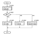
図18は、第1の実施形態におけるオブジェクト操作処理を示すフローチャートである。まず、ステップS1801において、上述の処理で特定された指定位置に対応するオブジェクトを取得し(オブジェクト取得処理)、ステップS1802で分岐する。ここで、指定操作が表示指示の場合はステップS1803へ進み、特定されたオブジェクトの再生処理を実行し(オブジェクト再生処理)、この処理を終了する。 FIG. 18 is a flowchart illustrating object operation processing according to the first embodiment. First, in step S1801, an object corresponding to the designated position specified in the above process is acquired (object acquisition process), and the process branches in step S1802. If the designation operation is a display instruction, the process advances to step S1803 to execute the specified object reproduction process (object reproduction process), and the process ends.
また、ステップS1802において、指定操作が印刷指示の場合はステップS1804へ進み、特定されたオブジェクトの印刷処理を実行し(オブジェクト印刷処理)、この処理を終了する。また、指定操作が検索指示の場合はステップS1805へ進み、特定されたオブジェクトが変化するタイミングを検索し、その位置からの映像を再生し(オブジェクト検索再生処理)、この処理を終了する。 If it is determined in step S1802 that the designation operation is a print instruction, the process advances to step S1804 to execute print processing for the identified object (object print processing), and the processing ends. If the designation operation is a search instruction, the process advances to step S1805 to search for the timing at which the specified object changes, play the video from that position (object search / playback process), and end this process.
このように、第1の実施形態によれば、機器及び機器内オブジェクトを再生映像中から特定することができる。また、特定されたオブジェクトに対する拡大表示や印刷等の操作が可能となる。特に、ディスプレイ上の表示オブジェクトを特定することができる。 As described above, according to the first embodiment, the device and the in-device object can be specified from the playback video. In addition, operations such as enlargement display and printing can be performed on the specified object. In particular, a display object on the display can be specified.
[第2の実施形態]
次に、図19〜図23を用いて、本発明に係る第2の実施形態を詳細に説明する。第2の実施形態では、特に対象機器がプリンタであり、再生映像中から指示された時間的位置と空間的位置に対応する機器及び機器内オブジェクトを特定し、拡大表示や印刷等の操作を行う場合を例に挙げて説明する。
[Second Embodiment]
Next, the second embodiment according to the present invention will be described in detail with reference to FIGS. In the second embodiment, in particular, the target device is a printer, the device and the object in the device corresponding to the temporal position and the spatial position instructed from the playback video are specified, and operations such as enlargement display and printing are performed. A case will be described as an example.
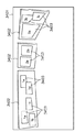
図19は、第2の実施形態におけるプリンタを含むシステムイメージの一例を示す図である。図19に示すシステムは会議室をイメージしており、通常の会議室に存在する会議机の他に、大画面のディスプレイ1902が2台と、プリンタ1904が2台と、会議の様子を広角で撮影するカメラ1901とで構成されている。また、各ディスプレイ画面上には複数の表示オブジェクト1903が表示されており、各プリンタの出力トレイ上には複数の印刷オブジェクト1905が置かれている様子が示されている。
FIG. 19 is a diagram illustrating an example of a system image including a printer according to the second embodiment. The system shown in FIG. 19 is an image of a conference room. In addition to a conference desk that exists in a normal conference room, there are two large-
図20は、プリンタを対象としたオブジェクト動作記録データの一例を示す図である。図20に示すように、オブジェクト動作記録データには、機器及び機器内オブジェクトを特定するための情報、そのオブジェクトが動作した時刻及び動作種別、印刷トレイが記録されている。 FIG. 20 is a diagram illustrating an example of object action record data for a printer. As shown in FIG. 20, in the object action record data, information for specifying a device and an object in the device, the time and action type at which the object has acted, and the print tray are recorded.
例えば、印刷装置1904で静止画4aが時刻2005/05/09 10:37:22に印刷トレイa上に印刷されたことがオブジェクト動作記録データ2001として記録されている。また、そのオブジェクトが受け取られたことがオブジェクト動作記録データ2004として記録されている。
For example, the fact that the
図21は、第2の実施形態におけるオブジェクト動作記録処理を示すフローチャートである。まず、ステップS2101において、記録対象機器を判定し、ディスプレイの場合はステップS2102へ進み、オブジェクト動作記録データからオブジェクトの動作種別を取得する(アクション取得処理)。そして、ステップS2103において、動作種別を判定し、動作種別が「表示」又は「移動完了」の場合はステップS2104へ進み、ディスプレイ内におけるオブジェクトの表示領域を取得する(ディスプレイ内座標取得処理)。 FIG. 21 is a flowchart showing object action recording processing in the second embodiment. First, in step S2101, the recording target device is determined. If the device is a display, the process proceeds to step S2102 to acquire the object action type from the object action record data (action acquisition process). In step S2103, the action type is determined. If the action type is “display” or “movement completed”, the process advances to step S2104 to acquire the display area of the object in the display (intra-display coordinate acquisition process).
また、ステップS2103において、動作種別が「非表示」の場合はステップS2105へ進み、各表示装置上での操作時刻からシステムの絶対時刻を取得する(絶対時刻取得処理)。次に、ステップS2106において、この処理で取得した情報をオブジェクト動作記録データとして記録し(記録処理)、この処理を終了する。また、ステップS2103において、動作種別が上記以外の場合には、この処理を終了する。 If the operation type is “non-display” in step S2103, the process advances to step S2105 to acquire the absolute time of the system from the operation time on each display device (absolute time acquisition process). Next, in step S2106, the information acquired in this process is recorded as object action recording data (recording process), and this process ends. If it is determined in step S2103 that the action type is other than the above, this process ends.
また、ステップS2101において、記録対象機器がプリンタの場合はステップS2107へ進み、オブジェクト動作記録データからオブジェクトの動作種別を取得する(アクション取得処理)。そして、ステップS2108において、動作種別を判定し、動作種別が「印刷」の場合はステップS2109へ進み、オブジェクトの出力トレイを取得する(プリンタ出力トレイ取得処理)。 In step S2101, if the recording target device is a printer, the process advances to step S2107 to acquire the object action type from the object action record data (action acquisition process). In step S2108, the operation type is determined. If the operation type is “print”, the process advances to step S2109 to acquire the output tray of the object (printer output tray acquisition process).
また、ステップS2108において、動作種別が「受取」の場合はステップS2110へ進み、各印刷装置上での操作時刻からシステムの絶対時刻を取得する(絶対時刻取得処理)。次に、ステップS2111において、この処理で取得した情報をオブジェクト動作記録データとして記録し(記録処理)、この処理を終了する。また、ステップS2108において、動作種別が上記以外の場合には、この処理を終了する。 If the operation type is “reception” in step S2108, the process advances to step S2110 to acquire the absolute time of the system from the operation time on each printing apparatus (absolute time acquisition processing). Next, in step S2111, the information acquired in this process is recorded as object action recording data (recording process), and this process ends. If it is determined in step S2108 that the action type is other than the above, this process ends.
図22は、プリンタの機器位置形状データの一例を示す図である。図22に示すように、機器位置形状データには、機器、出力トレイ、機器に対する動作時刻、動作種別(アクション)、映像上での位置形状(左上、左下、右上、右下)を特定するための情報が記録されている。 FIG. 22 is a diagram illustrating an example of the device position shape data of the printer. As shown in FIG. 22, the device position shape data specifies the device, the output tray, the operation time for the device, the operation type (action), and the position shape on the video (upper left, lower left, upper right, lower right). Is recorded.
例えば、印刷装置1404の出力トレイbが時刻2005/02/01 00:00:00に設置されたことが機器位置形状データ2204として記録されている。また、その出力トレイbが撤去されたことが機器位置形状データ2205として記録されている。
For example, the fact that the output tray b of the printing apparatus 1404 is installed at
図23は、第2の実施形態における指定機器内オブジェクト特定処理を示すフローチャートである。まず、ステップS2301において、再生位置に対応する時刻の機器位置形状データを取得する(オブジェクト位置形状取得処理)。次に、ステップS2302において、機器位置形状データから指定位置に対応する出力トレイを求める(プリンタ出力トレイ特定処理)。そして、ステップS2303において、指定位置に対応するオブジェクト動作記録データを検索し(オブジェクト動作検索処理)、この処理を終了する。 FIG. 23 is a flowchart illustrating the specified-device-specific object specifying process according to the second embodiment. First, in step S2301, device position shape data at a time corresponding to a reproduction position is acquired (object position shape acquisition process). Next, in step S2302, an output tray corresponding to the designated position is obtained from the device position shape data (printer output tray specifying process). In step S2303, object action record data corresponding to the designated position is searched (object action search process), and this process ends.
このように、第2の実施形態によれば、特にプリンタ出力トレイ上の印刷オブジェクトを特定することができる。 As described above, according to the second embodiment, a print object on the printer output tray can be specified.
[第3の実施形態]
次に、図24〜図25を用いて、本発明に係る第3の実施形態を詳細に説明する。第3の実施形態では、再生映像中に表示されている機器の位置形状をユーザが指定する場合を例に挙げて説明する。
[Third Embodiment]
Next, the third embodiment according to the present invention will be described in detail with reference to FIGS. In the third embodiment, a case where the user designates the position shape of the device displayed in the playback video will be described as an example.
図24は、会議映像中に表示されている機器の表示領域を指示可能な機器位置形状指示画面の一例を示す図である。図24に示す機器位置形状指示画面を用いることで再生中の会議映像2407の任意表示領域2408を任意機器2406の位置形状として指示することができる。
FIG. 24 is a diagram illustrating an example of a device position shape instruction screen that can indicate the display area of the device displayed in the conference video. By using the device position shape instruction screen shown in FIG. 24, the
また、図24に示す機器位置形状指示画面には、指示対象となる機器一覧が表示され、その一覧に対する追加2403、変更2404、削除2405の指示ボタンが配置されており、更に確定2401、取消2402の指示ボタンが配置されている。
In addition, on the device position shape instruction screen shown in FIG. 24, a list of devices to be instructed is displayed, instruction buttons for addition 2403, change 2404, and
図25は、第3の実施形態における機器位置形状指示処理を示すフローチャートである。まず、ステップS2501において、行われた操作を判別し、操作が「追加」の指示の場合はステップS2502へ進み、システムを構成する機器を追加する(機器追加処理)。そして、ステップS2503において、その機器に対する再生映像中での位置形状を指示し(位置形状変更処理)、ステップS2501に戻り、上述の処理を繰り返す。 FIG. 25 is a flowchart illustrating an apparatus position shape instruction process according to the third embodiment. First, in step S2501, the operation that has been performed is determined. If the operation is an “add” instruction, the process proceeds to step S2502, and a device configuring the system is added (device addition processing). In step S2503, the position shape in the playback video for the device is instructed (position shape change process), the process returns to step S2501, and the above-described process is repeated.
また、ステップS2501において、操作が「変更」の指示の場合にはステップS2503へ進み、位置形状変更処理を行う。また、操作が「削除」の指示の場合はステップS2504へ進み、選択中の機器を削除し(機器削除処理)、ステップS2501に戻り、上述の処理を繰り返す。 If it is determined in step S2501 that the operation is a “change” instruction, the process advances to step S2503 to perform position shape change processing. If the operation is a “delete” instruction, the process advances to step S2504 to delete the selected device (device deletion process), and the process returns to step S2501 to repeat the above process.
また、ステップS2501において、操作が「取消」の指示の場合は、この処理を終了する。また、操作が「確定」の指示の場合はステップS2505へ進み、これまでに変更された内容を確定し(変更確定処理)、この処理を終了する。 If it is determined in step S2501 that the operation is a “cancel” instruction, the process ends. If the operation is a “confirm” instruction, the process advances to step S2505 to confirm the contents that have been changed so far (change confirmation process), and the process ends.
このように、第3の実施形態によれば、明示的に再生映像中の機器の位置と形状を指定することができる。 Thus, according to the third embodiment, the position and shape of the device in the playback video can be explicitly specified.
[第4の実施形態]
次に、図26〜図28を用いて、本発明に係る第4の実施形態を詳細に説明する。第4の実施形態では、特に対象機器がディスプレイであり、機器に特定の動作を促すことで、撮影映像中に表示されている機器の位置形状をユーザが指定しなくても、自動設定可能とする場合を例に挙げて説明する。
[Fourth Embodiment]
Next, the fourth embodiment according to the present invention will be described in detail with reference to FIGS. In the fourth embodiment, in particular, the target device is a display, and by prompting the device to perform a specific operation, the device can be automatically set without specifying the position shape of the device displayed in the captured video. An example of the case will be described.
図26は、撮影映像中に表示されている機器の表示領域を自動設定可能な機器位置形状指示画面の一例を示す図である。図26に示す機器位置形状指示画面により撮影映像中の会議映像2607に表示中の任意機器2606の表示領域2608に映像変化を促すことで、位置形状を自動設定することができる。
FIG. 26 is a diagram illustrating an example of a device position shape instruction screen that can automatically set the display area of the device displayed in the captured video. The position shape can be automatically set by prompting the
また、図26に示す機器位置形状指示画面には、指示対象となる機器一覧が表示され、その一覧に対する追加2603、自動設定2604、削除2605の指示ボタンが配置されており、更に確定2601、取消2602の指示ボタンが配置されている。
In addition, on the device position shape instruction screen shown in FIG. 26, a list of devices to be specified is displayed, and instruction buttons for addition 2603, automatic setting 2604, and deletion 2605 are arranged on the list, and further,
図27は、第4の実施形態における機器位置形状指示処理を示すフローチャートである。まず、ステップS2701において、行われた操作を判別し、操作が「追加」の指示の場合はステップS2702へ進み、システムを構成する機器を追加する(機器追加処理)。そして、ステップS2703において、その機器に対する再生映像中での位置形状を自動設定し(位置形状自動設定処理)、ステップS2701に戻り、上述の処理を繰り返す。 FIG. 27 is a flowchart illustrating an apparatus position shape instruction process according to the fourth embodiment. First, in step S2701, the operation that has been performed is determined. If the operation is an “add” instruction, the process proceeds to step S2702, and a device configuring the system is added (device addition processing). In step S2703, the position shape in the playback video for the device is automatically set (position shape automatic setting processing), and the process returns to step S2701 to repeat the above processing.
また、ステップS2701において、操作が「自動設定」の指示の場合はステップS2703へ進み、位置形状自動設定処理を行う。また、操作が「削除」の指示の場合はステップS2704へ進み、選択中の機器を削除し(機器削除処理)、ステップS2701に戻り、上述の処理を繰り返す。 If it is determined in step S2701 that the operation is an “automatic setting” instruction, the process advances to step S2703 to perform position shape automatic setting processing. If the operation is a “delete” instruction, the process advances to step S2704 to delete the selected device (device deletion process), and the process returns to step S2701 to repeat the above process.
また、ステップS2701において、操作が「取消」の指示の場合は、この処理を終了する。また、操作が「確定」の指示の場合はステップS2705へ進み、これまでに変更された内容を確定し(変更確定処理)、この処理を終了する。 If it is determined in step S2701 that the operation is a “cancel” instruction, the process ends. If the operation is a “confirm” instruction, the process advances to step S2705 to confirm the contents that have been changed so far (change confirmation process), and the process ends.
図28は、第4の実施形態における位置形状自動設定処理を示すフローチャートである。まず、ステップS2801において、後述する処理による映像変化が現れる前の映像を撮影する(撮影処理)。そして、ステップS2802において、自動設定対象となるディスプレイ上に特定のパターンの映像を表示させる(特定パターン表示処理)。その結果、ステップS2803において、変化後の映像を撮影し(撮影処理)、ステップS2804で変化前後の映像の差分を抽出する(映像差分抽出処理)。そして、ステップS2805において、その差分に基づいて位置形状を推測・設定し(機器位置形状確定処理)、この処理を終了する。 FIG. 28 is a flowchart showing a position shape automatic setting process in the fourth embodiment. First, in step S2801, a video before a video change due to processing described later is shot (shooting processing). In step S2802, a video with a specific pattern is displayed on the display to be automatically set (specific pattern display processing). As a result, in step S2803, the video after the change is shot (shooting process), and in step S2804, the difference between the videos before and after the change is extracted (video difference extraction process). In step S2805, a position shape is estimated and set based on the difference (apparatus position shape determination process), and this process ends.
このように、第4の実施形態によれば、明示的に再生映像中の機器の位置と形状を指定しなくても、再生映像中の機器の位置と形状を推測することができる。特に、再生映像中のディスプレイの位置と形状を推測することができる。 Thus, according to the fourth embodiment, the position and shape of the device in the playback video can be estimated without explicitly specifying the position and shape of the device in the playback video. In particular, the position and shape of the display in the playback video can be estimated.
[第5の実施形態]
次に、図29〜図30を用いて、本発明に係る第5の実施形態を詳細に説明する。第5の実施形態では、特に対象機器がプリンタであり、機器に特定の動作を促すことで、撮影映像中に表示されている機器の位置形状をユーザが指定しなくても、自動設定可能とする場合を例に挙げて説明する。
[Fifth Embodiment]
Next, the fifth embodiment according to the present invention will be described in detail with reference to FIGS. In the fifth embodiment, in particular, the target device is a printer, and by prompting the device to perform a specific operation, it is possible to automatically set the device without specifying the position shape of the device displayed in the captured video. An example of the case will be described.
図29は、撮影映像中に表示されているプリンタの表示領域を自動設定可能な機器位置形状指示画面の一例を示す図である。図29に示す機器位置形状指示画面により撮影映像中の会議映像2907に表示中の印刷装置2906の出力トレイ表示領域2908に映像変化を促すことで、位置形状を自動設定することができる。
FIG. 29 is a diagram illustrating an example of a device position shape instruction screen that can automatically set the display area of the printer displayed in the captured video. The position shape can be automatically set by prompting the image change in the output
また、図29に示す機器位置形状指示画面には、指示対象となる機器一覧が表示され、その一覧に対する追加2903、自動設定2904、削除2905の指示ボタンが配置されており、更に確定2901、取消2902の指示ボタンが配置されている。
In addition, a list of devices to be specified is displayed on the device position shape instruction screen shown in FIG. 29. Instruction buttons for addition 2903, automatic setting 2904, and deletion 2905 are arranged on the list, and further,
図30は、第5の実施形態におけるプリンタ出力トレイの位置形状自動設定処理を示すフローチャートである。まず、ステップS3001において、対象を自動設定対象機器に対応する出力トレイリストの先頭に初期化し、ステップS3002以降の処理を繰り返す。ステップS3002において、対象を判定し、対象が有効の場合はステップS3003へ進み、後述する処理による映像変化が現れる前の映像を撮影する(撮影処理)。そして、ステップS3004において、自動設定対象となるプリンタの出力トレイに特定のパターンの映像を印刷させる(特定パターン印刷処理)。その結果、ステップS3005において、変化後の映像を撮影し(撮影処理)、ステップS3006において、変化前後の映像の差分を抽出する(映像差分抽出処理)。そして、ステップS3007において、その差分に基づいて位置形状を推測・設定し(出力トレイ位置形状確定処理)、ステップS3008において、対象を進め、ステップS3002に戻り、上述の処理を繰り返す。一方、ステップS3002において、対象が有効でない場合は、この処理を終了する。 FIG. 30 is a flowchart illustrating a position shape automatic setting process for a printer output tray according to the fifth embodiment. First, in step S3001, the target is initialized to the top of the output tray list corresponding to the automatic setting target device, and the processing from step S3002 is repeated. In step S3002, a target is determined. If the target is valid, the process proceeds to step S3003, and a video before a video change due to processing described later is shot (shooting processing). In step S3004, a specific pattern video is printed on the output tray of the printer to be automatically set (specific pattern printing process). As a result, in step S3005, the video after the change is shot (shooting process), and in step S3006, the difference between the videos before and after the change is extracted (video difference extraction process). In step S3007, a position shape is estimated and set based on the difference (output tray position shape determination process). In step S3008, the target is advanced, and the process returns to step S3002, and the above-described processing is repeated. On the other hand, if the target is not valid in step S3002, this process ends.
このように、第5の実施形態によれば、特に再生映像中のプリンタ出力トレイの位置と形状を推測することができる。 Thus, according to the fifth embodiment, it is possible to infer the position and shape of the printer output tray particularly in the reproduced video.
[第6の実施形態]
次に、図31〜図33を用いて、本発明に係る第6の実施形態を詳細に説明する。第6の実施形態では、議事録内の会議映像スナップショットを用いて、指示された時間的位置と空間的位置に対応する機器及び機器内オブジェクトを特定し、拡大表示や印刷等の操作を行う場合を例に挙げて説明する。
[Sixth Embodiment]
Next, the sixth embodiment according to the present invention will be described in detail with reference to FIGS. In the sixth embodiment, by using the meeting video snapshot in the minutes, the device and the object in the device corresponding to the designated temporal position and spatial position are specified, and operations such as enlarged display and printing are performed. A case will be described as an example.
図31は、第6の実施形態における会議記録処理を示すフローチャートである。まず、ステップS3101において、上述の撮影映像データへの記録を開始する(映像撮影開始処理)。そして、ステップS3102において、ユーザによる操作を受け付け(会議操作処理)、次のステップS3103で操作を判定する。ここで、操作がオブジェクト操作の指示の場合はステップS3104へ進み、対応するオブジェクトの表示を更新する(オブジェクト表示更新処理)。そして、ステップS3105において、その表示更新動作を上述のオブジェクト動作記録データに記録し(オブジェクト動作記録処理)、ステップS3102に戻り、上述の処理を繰り返す。 FIG. 31 is a flowchart showing conference recording processing in the sixth embodiment. First, in step S3101, recording into the above-described photographed video data is started (video photographing start process). In step S3102, an operation by the user is accepted (conference operation process), and the operation is determined in the next step S3103. If the operation is an object operation instruction, the process advances to step S3104 to update the display of the corresponding object (object display update process). In step S3105, the display update operation is recorded in the object action record data (object action record process), the process returns to step S3102, and the above process is repeated.
また、ステップS3103において、操作が議事録追加操作の指示の場合はステップS3106へ進み、指示時点での会議映像を撮影する(静止画撮影処理)。そして、ステップS3107において、その会議映像を含む議事録データを追加し(議事録追加処理)、ステップS3102に戻り、上述の処理を繰り返す。また、ステップS3103において、操作が終了指示の場合はステップS3108へ進み、撮影を終了し(映像撮影終了処理)、この処理を終了する。 If it is determined in step S3103 that the operation is an instruction to add a minutes, the process proceeds to step S3106 to shoot a conference video at the time of the instruction (still image shooting process). In step S3107, the minutes data including the meeting video is added (minutes addition process), and the process returns to step S3102 to repeat the above process. If it is determined in step S3103 that the operation is an end instruction, the process advances to step S3108 to end shooting (video shooting end process), and this process ends.
図32は、第6の実施形態における議事録操作画面の一例を示す図である。図32に示す議事録画面には、上述の議事録追加操作時の時刻、表示オブジェクト、静止画会議映像3202、3203、3204が表示されており、スクロールバー3201で操作可能に構成されている。また、任意の時刻の静止画会議映像上で、位置指定操作3205で表示オブジェクトに対する操作指示が行われると、操作可能なオブジェクト操作指示3206が表示されるように構成されている。
FIG. 32 is a diagram illustrating an example of a minutes operation screen according to the sixth embodiment. On the proceeding recording screen shown in FIG. 32, the time at the time of the above-described proceeding for adding the minutes, display objects, and still image
図33は、第6の実施形態における議事録操作処理を示すフローチャートである。まず、ステップS3301において、操作対象となる議事録が指定され(議事録指定処理)、ステップS3302において、操作指示が行われる(議事録操作処理)。そして、ステップS3303において、操作指示を判定し、操作指示がスクロールバー3201を用いた「議事録位置変更」指示の場合はステップS3304へ進み、議事録の表示位置を変更する(議事録位置変更処理)。そして、ステップS3302に戻り、上述の処理を繰り返す。
FIG. 33 is a flowchart showing minutes operation processing in the sixth embodiment. First, in step S3301, the minutes to be operated are designated (minutes designation process), and in step S3302, an operation instruction is given (minutes operation process). In step S3303, an operation instruction is determined. If the operation instruction is a “change minutes position” instruction using the
また、ステップS3303において、操作指示が「映像位置指定」指示の場合はステップS3305へ進み、議事録位置に対応する時刻の機器位置形状データを取得する(機器位置形状取得処理)。そして、ステップS3306において、指定位置に対応する機器を特定する(指定機器特定処理)。次に、ステップS3307において、オブジェクト動作記録データを参照することで指定位置に対応する機器内オブジェクトを特定し(指定機器内オブジェクト特定処理)、ステップS3302に戻り、上述の処理を繰り返す。 If it is determined in step S3303 that the operation instruction is a “video position designation” instruction, the process advances to step S3305 to acquire device position shape data at a time corresponding to the minutes position (device position shape acquisition process). In step S3306, a device corresponding to the specified position is specified (specified device specifying process). Next, in step S3307, the in-device object corresponding to the specified position is specified by referring to the object action record data (specified in-device object specifying process), the process returns to step S3302, and the above-described processing is repeated.
また、ステップS3303において、操作指示が「オブジェクト操作」の指示の場合はステップS3308へ進み、上述した手順で特定されたオブジェクトに対する指定された操作を実行する(オブジェクト操作処理)。そして、ステップS3302に戻り、上述の処理を繰り返す。また、ステップS3303において、操作指示が「終了」指示の場合は、この処理を終了する。 If it is determined in step S3303 that the operation instruction is “object operation”, the process advances to step S3308 to execute the specified operation on the object specified in the above-described procedure (object operation processing). And it returns to step S3302 and repeats the above-mentioned processing. In step S3303, if the operation instruction is an “end” instruction, the process ends.
このように、第6の実施形態によれば、機器及び機器内オブジェクトを議事録に含まれる会議映像のスナップショットから特定することができる。 As described above, according to the sixth embodiment, the device and the in-device object can be specified from the snapshot of the conference video included in the minutes.
[第7の実施形態]
次に、図34〜図35を用いて、本発明に係る第7の実施形態を詳細に説明する。第7の実施形態では、生成される会議映像中の機器の位置や形状の情報から会議中に行われた動作に対応する会議映像を生成する場合を例に挙げて説明する。
[Seventh Embodiment]
Next, the seventh embodiment according to the present invention will be described in detail with reference to FIGS. In the seventh embodiment, a case where a conference video corresponding to an operation performed during the conference is generated from information on the position and shape of the device in the generated conference video will be described as an example.
図34は、第7の実施形態で生成された仮想映像の一例を示す図である。図34に示すように、会議映像画面3401上には上述の機器位置形状データに基づいてディスプレイ3402が配置され、上述のオブジェクト動作記録データに基づいて対応する時刻の表示オブジェクト3403が表示される。
FIG. 34 is a diagram illustrating an example of the virtual video generated in the seventh embodiment. As shown in FIG. 34, a
図35は、第7の実施形態における仮想映像生成処理を示すフローチャートである。まず、ステップS3501において、仮想映像を初期化し、ステップS3502で、対象をオブジェクト動作記録データの先頭に初期化し、ステップS3503以降の処理を繰り返す。 FIG. 35 is a flowchart showing virtual video generation processing in the seventh embodiment. First, in step S3501, the virtual video is initialized, and in step S3502, the target is initialized to the head of the object action record data, and the processing from step S3503 is repeated.
ステップS3503では、対象が有効か否かを判定し、有効の場合はステップS3504へ進み、対象のオブジェクト動作記録データから対応する時刻の仮想映像を追加する(仮想映像追加処理)。そして、ステップS3505において、対象を進め、ステップS3502に戻り、上述の処理を繰り返す。一方、ステップS3503において、対象が有効でない、即ち終了の場合は、この処理を終了する。 In step S3503, it is determined whether or not the target is valid. If the target is valid, the process proceeds to step S3504, and a virtual video at a corresponding time is added from the target object action record data (virtual video addition processing). In step S3505, the target is advanced, and the process returns to step S3502 to repeat the above-described processing. On the other hand, if it is determined in step S3503 that the target is not valid, that is, if it is terminated, this process is terminated.
このように、第7の実施形態によれば、仮想的な会議映像を生成することができる。 Thus, according to the seventh embodiment, a virtual conference video can be generated.
[第8の実施形態]
次に、図36〜図37を用いて、本発明に係る第8の実施形態を詳細に説明する。第8の実施形態では、再生映像中から指示された時間的位置と空間的位置に対応する機器及び機器内オブジェクトを特定し、そのオブジェクトが変化したタイミングの映像を検索して再生する場合を例に挙げて説明する。
[Eighth Embodiment]
Next, the eighth embodiment according to the present invention will be described in detail with reference to FIGS. In the eighth embodiment, an example is described in which a device and an object in the device corresponding to an instructed temporal position and spatial position are specified from the playback video, and a video at a timing when the object is changed is searched for and played back. Will be described.
図36は、第8の実施形態におけるオブジェクト検索再生処理を示すフローチャートである。まず、ステップS3601において、指定位置で特定されたオブジェクトが変化したタイミングを特定する(オブジェクト変化特定処理)。そして、ステップS3602において、そのタイミングから映像を再生する(映像再生処理)。 FIG. 36 is a flowchart showing object search / playback processing in the eighth embodiment. First, in step S3601, the timing at which the object specified at the specified position has changed is specified (object change specifying process). In step S3602, the video is played back from that timing (video playback processing).
図37は、第8の実施形態におけるオブジェクト変化特定処理を示すフローチャートである。まず、ステップS3701において、対象が指定位置で特定されたオブジェクトに対応するオブジェクト動作記録データの位置に初期化し、ステップS3702以降の処理を繰り返す。 FIG. 37 is a flowchart showing object change specifying processing in the eighth embodiment. First, in step S3701, the target is initialized to the position of the object motion record data corresponding to the object specified at the designated position, and the processing in step S3702 and subsequent steps is repeated.
ステップS3702では、対象が有効か否かを判定し、有効の場合はステップS3703へ進み、そのオブジェクトと同一か否かを判定する。その結果、同一と判定した場合には対象のオブジェクト動作記録データを戻り値として、この処理を終了する。また、同一と判定しなかった場合にはステップS3704へ進み、対象を進め、ステップS3702に戻り、上述の処理を繰り返す。一方、ステップS3702において、対象が有効でない、即ち終了の場合には、特定失敗として、この処理を終了する。 In step S3702, it is determined whether the target is valid. If valid, the process advances to step S3703 to determine whether the object is the same. As a result, when it is determined that they are the same, the target object action record data is used as a return value, and this process is terminated. On the other hand, if they are not determined to be the same, the process proceeds to step S3704, the target is advanced, the process returns to step S3702, and the above-described processing is repeated. On the other hand, in step S3702, if the target is not valid, that is, if it is terminated, this processing is terminated as a specific failure.
尚、上述した実施形態の他にも、再生映像中から指示された位置の映像的変化があったタイミングを検索した後、そのタイミングで機器及び機器内オブジェクトを特定し、再生する例も想定される。 In addition to the above-described embodiment, an example in which a device and an object in the device are identified and reproduced at the timing after searching for the timing at which the indicated position in the playback video has occurred is assumed. The
以上説明したように、本実施形態によれば、再生映像中から特定された機器及び機器内オブジェクトが変化したタイミングの映像を再生することができる。 As described above, according to the present embodiment, it is possible to reproduce a video at a timing when the device specified in the reproduced video and the object in the device change.
尚、本発明は複数の機器(例えば、ホストコンピュータ,インターフェース機器,リーダ,プリンタなど)から構成されるシステムに適用しても、1つの機器からなる装置(例えば、複写機,ファクシミリ装置など)に適用しても良い。 Even if the present invention is applied to a system composed of a plurality of devices (for example, a host computer, an interface device, a reader, a printer, etc.), it is applied to an apparatus (for example, a copier, a facsimile machine, etc.) composed of a single device. It may be applied.
また、前述した実施形態の機能を実現するソフトウェアのプログラムコードを記録した記録媒体を、システム或いは装置に供給し、そのシステム或いは装置のコンピュータ(CPU若しくはMPU)が記録媒体に格納されたプログラムコードを読出し実行する。これによっても、本発明の目的が達成されることは言うまでもない。 In addition, a recording medium in which a program code of software for realizing the functions of the above-described embodiments is recorded is supplied to the system or apparatus, and the computer (CPU or MPU) of the system or apparatus stores the program code stored in the recording medium. Read and execute. It goes without saying that the object of the present invention can also be achieved by this.
この場合、記録媒体から読出されたプログラムコード自体が前述した実施形態の機能を実現することになり、そのプログラムコードを記憶した記録媒体は本発明を構成することになる。 In this case, the program code itself read from the recording medium realizes the functions of the above-described embodiment, and the recording medium storing the program code constitutes the present invention.
このプログラムコードを供給するための記録媒体としては、例えばフロッピー(登録商標)ディスク,ハードディスク,光ディスク,光磁気ディスク,CD−ROM,CD−R,磁気テープ,不揮発性のメモリカード,ROMなどを用いることができる。 As a recording medium for supplying the program code, for example, a floppy (registered trademark) disk, a hard disk, an optical disk, a magneto-optical disk, a CD-ROM, a CD-R, a magnetic tape, a nonvolatile memory card, a ROM, or the like is used. be able to.
また、コンピュータが読出したプログラムコードを実行することにより、前述した実施形態の機能が実現されるだけでなく、次の場合も含まれることは言うまでもない。即ち、プログラムコードの指示に基づき、コンピュータ上で稼働しているOS(オペレーティングシステム)などが実際の処理の一部又は全部を行い、その処理により前述した実施形態の機能が実現される場合。 In addition, by executing the program code read by the computer, not only the functions of the above-described embodiments are realized, but also the following cases are included. That is, when the OS (operating system) running on the computer performs part or all of the actual processing based on the instruction of the program code, and the functions of the above-described embodiments are realized by the processing.
更に、記録媒体から読出されたプログラムコードがコンピュータに挿入された機能拡張ボードやコンピュータに接続された機能拡張ユニットに備わるメモリに書込む。その後、そのプログラムコードの指示に基づき、その機能拡張ボードや機能拡張ユニットに備わるCPUなどが実際の処理の一部又は全部を行い、その処理により前述した実施形態の機能が実現される場合も含まれることは言うまでもない。 Further, the program code read from the recording medium is written in a memory provided in a function expansion board inserted into the computer or a function expansion unit connected to the computer. After that, based on the instruction of the program code, the CPU of the function expansion board or function expansion unit performs part or all of the actual processing, and the function of the above-described embodiment is realized by the processing. Needless to say.
101 入力部
102 CPU
103 出力部
104 プログラムメモリ
105 データメモリ
106 バス
201 会議映像撮影カメラ
202 ディスプレイ
203 表示オブジェクト
301 表示装置
302 表示装置
303 表示装置
304 撮影装置
305 会議記録装置
306 オブジェクト動作記録データ
307 撮影映像データ
308 機器位置形状データ
309 会議記録再生装置
101
103
Claims (13)
前記映像データを再生中に所望のオブジェクトが指定された場合に、該オブジェクトの機器内の位置及び動作時刻に関する情報に基づいて前記オブジェクトを特定する特定手段と、
前記特定されたオブジェクトに対して所定の操作を実行可能とする操作手段とを有することを特徴とする映像処理装置。 A video processing device that captures a predetermined motion of an object performed by a device with a photographing device, records the image as video data, and then reproduces the video data,
A specifying unit for specifying the object based on information on a position of the object in a device and an operation time when a desired object is specified during reproduction of the video data;
An image processing apparatus comprising: an operation unit capable of executing a predetermined operation on the specified object.
前記特定されたタイミングの映像データを再生する再生手段とを更に有することを特徴とする請求項1記載の映像処理装置。 Object change specifying means for specifying the timing at which the object has changed;
The video processing apparatus according to claim 1, further comprising reproduction means for reproducing the video data at the specified timing.
前記映像データを再生中に所望のオブジェクトが指定された場合に、該オブジェクトの機器内の位置及び動作時刻に関する情報に基づいて前記オブジェクトを特定する特定工程と、
前記特定されたオブジェクトに対して所定の操作を実行可能とする操作工程とを有することを特徴とするオブジェクト特定方法。 A method for identifying an object of a video processing apparatus, wherein a predetermined operation of an object performed by a device is photographed by a photographing device, recorded as video data, and then reproduced.
A specifying step of specifying the object based on information on a position of the object in a device and an operation time when a desired object is specified during reproduction of the video data;
And an operation step of enabling a predetermined operation to be performed on the specified object.
Priority Applications (3)
| Application Number | Priority Date | Filing Date | Title |
|---|---|---|---|
| JP2005240197A JP2007060026A (en) | 2005-08-22 | 2005-08-22 | Video processing apparatus and object particularizing method |
| US11/503,994 US7898566B2 (en) | 2005-08-22 | 2006-08-15 | Video processing apparatus and object identifying method |
| CNB2006101098869A CN100544432C (en) | 2005-08-22 | 2006-08-22 | Video processing equipment and object identifying method |
Applications Claiming Priority (1)
| Application Number | Priority Date | Filing Date | Title |
|---|---|---|---|
| JP2005240197A JP2007060026A (en) | 2005-08-22 | 2005-08-22 | Video processing apparatus and object particularizing method |
Publications (2)
| Publication Number | Publication Date |
|---|---|
| JP2007060026A true JP2007060026A (en) | 2007-03-08 |
| JP2007060026A5 JP2007060026A5 (en) | 2008-10-02 |
Family
ID=37766991
Family Applications (1)
| Application Number | Title | Priority Date | Filing Date |
|---|---|---|---|
| JP2005240197A Pending JP2007060026A (en) | 2005-08-22 | 2005-08-22 | Video processing apparatus and object particularizing method |
Country Status (3)
| Country | Link |
|---|---|
| US (1) | US7898566B2 (en) |
| JP (1) | JP2007060026A (en) |
| CN (1) | CN100544432C (en) |
Cited By (1)
| Publication number | Priority date | Publication date | Assignee | Title |
|---|---|---|---|---|
| JP2013097808A (en) * | 2011-11-06 | 2013-05-20 | Sharp Corp | Meeting summary creation device, program, and computer-readable recording medium |
Families Citing this family (4)
| Publication number | Priority date | Publication date | Assignee | Title |
|---|---|---|---|---|
| FR2931330B1 (en) * | 2008-05-13 | 2011-04-01 | Kadrige | METHOD AND SYSTEM FOR AUTOMATICALLY RECORDING A COMMUNICATION SESSION |
| JP6323356B2 (en) * | 2015-02-03 | 2018-05-16 | 株式会社安川電機 | Processing system, monitoring method, and computer program |
| CN109218659A (en) * | 2017-07-06 | 2019-01-15 | 中兴通讯股份有限公司 | A kind of video interactive processing method, apparatus and system |
| CN107832799A (en) * | 2017-11-20 | 2018-03-23 | 北京奇虎科技有限公司 | Object identifying method and device, computing device based on camera scene |
Citations (6)
| Publication number | Priority date | Publication date | Assignee | Title |
|---|---|---|---|---|
| JPH1040068A (en) * | 1996-07-26 | 1998-02-13 | Fuji Xerox Co Ltd | Method for recording conference information and device therefore and device for reproducing convention information |
| JP2001331614A (en) * | 2000-05-19 | 2001-11-30 | Sony Corp | Network conference system, conference minutes generating method, conference managing server, and conference minutes generating method |
| JP2003087758A (en) * | 2001-09-14 | 2003-03-20 | Sony Corp | Information generating method and network information processing system |
| JP2004145482A (en) * | 2002-10-22 | 2004-05-20 | Matsushita Electric Ind Co Ltd | Image retrieval device |
| JP2005051778A (en) * | 2003-07-28 | 2005-02-24 | Fuji Xerox Co Ltd | Integrated system for providing shared interactive environment, computer data signal, program, system, method for exchanging information in shared interactive environment, and method for annotating live video image |
| JP2006148730A (en) * | 2004-11-24 | 2006-06-08 | Hitachi Omron Terminal Solutions Corp | Conference system and conference information providing method |
Family Cites Families (8)
| Publication number | Priority date | Publication date | Assignee | Title |
|---|---|---|---|---|
| JP4154015B2 (en) | 1997-12-10 | 2008-09-24 | キヤノン株式会社 | Information processing apparatus and method |
| JP2000023123A (en) * | 1998-06-30 | 2000-01-21 | Nec Corp | Video telephone system |
| US6992702B1 (en) | 1999-09-07 | 2006-01-31 | Fuji Xerox Co., Ltd | System for controlling video and motion picture cameras |
| DK1362476T3 (en) * | 2000-01-31 | 2010-06-07 | Supponor Ltd | Method of manipulating a visible object recorded with a television camera |
| US6771303B2 (en) * | 2002-04-23 | 2004-08-03 | Microsoft Corporation | Video-teleconferencing system with eye-gaze correction |
| US7260257B2 (en) * | 2002-06-19 | 2007-08-21 | Microsoft Corp. | System and method for whiteboard and audio capture |
| JP4015018B2 (en) | 2002-12-26 | 2007-11-28 | 株式会社リコー | Recording apparatus, recording method, and recording program |
| JP2005352933A (en) * | 2004-06-14 | 2005-12-22 | Fuji Xerox Co Ltd | Display arrangement, system, and display method |
-
2005
- 2005-08-22 JP JP2005240197A patent/JP2007060026A/en active Pending
-
2006
- 2006-08-15 US US11/503,994 patent/US7898566B2/en not_active Expired - Fee Related
- 2006-08-22 CN CNB2006101098869A patent/CN100544432C/en not_active Expired - Fee Related
Patent Citations (6)
| Publication number | Priority date | Publication date | Assignee | Title |
|---|---|---|---|---|
| JPH1040068A (en) * | 1996-07-26 | 1998-02-13 | Fuji Xerox Co Ltd | Method for recording conference information and device therefore and device for reproducing convention information |
| JP2001331614A (en) * | 2000-05-19 | 2001-11-30 | Sony Corp | Network conference system, conference minutes generating method, conference managing server, and conference minutes generating method |
| JP2003087758A (en) * | 2001-09-14 | 2003-03-20 | Sony Corp | Information generating method and network information processing system |
| JP2004145482A (en) * | 2002-10-22 | 2004-05-20 | Matsushita Electric Ind Co Ltd | Image retrieval device |
| JP2005051778A (en) * | 2003-07-28 | 2005-02-24 | Fuji Xerox Co Ltd | Integrated system for providing shared interactive environment, computer data signal, program, system, method for exchanging information in shared interactive environment, and method for annotating live video image |
| JP2006148730A (en) * | 2004-11-24 | 2006-06-08 | Hitachi Omron Terminal Solutions Corp | Conference system and conference information providing method |
Cited By (1)
| Publication number | Priority date | Publication date | Assignee | Title |
|---|---|---|---|---|
| JP2013097808A (en) * | 2011-11-06 | 2013-05-20 | Sharp Corp | Meeting summary creation device, program, and computer-readable recording medium |
Also Published As
| Publication number | Publication date |
|---|---|
| CN100544432C (en) | 2009-09-23 |
| CN1921620A (en) | 2007-02-28 |
| US7898566B2 (en) | 2011-03-01 |
| US20070040902A1 (en) | 2007-02-22 |
Similar Documents
| Publication | Publication Date | Title |
|---|---|---|
| JP4816140B2 (en) | Image processing system and method, image processing apparatus and method, imaging apparatus and method, program recording medium, and program | |
| US20110050963A1 (en) | Image capturing apparatus and image encoding apparatus | |
| JP5133816B2 (en) | Camera, image composition method, and program | |
| KR101530826B1 (en) | Playing method and the system of 360 degree spacial video | |
| JP2005318125A (en) | Method for dividing and recording data, method for dividing and recording data of electronic camera, and the electronic camera | |
| JP2009147824A (en) | Imaging apparatus and imaging method | |
| KR20160021706A (en) | Playing method and the system of 360 degree spacial video | |
| CN101601067B (en) | Image recording device and image recording method | |
| CN103813094A (en) | Electronic device and related method capable of capturing images, and machine readable storage medium | |
| JP5759212B2 (en) | Scenario editing apparatus, scenario editing method, and imaging system | |
| JP2007060026A (en) | Video processing apparatus and object particularizing method | |
| JP2002176613A (en) | Moving image editing unit, moving image editing method and recording medium | |
| JP2007060028A (en) | Image processor and object processing method | |
| JP2009055593A (en) | Image reproducer, image reproduction method, and image reproduction program | |
| JP2006203334A (en) | Image recording apparatus, control method thereof and program | |
| JP4698961B2 (en) | Electronic camera and electronic camera control program | |
| US20120219264A1 (en) | Image processing device | |
| JP2007324663A (en) | Video camera | |
| JP2006245921A (en) | Imaging device and system, mobile telephone, control method, and program | |
| CN100585721C (en) | Image sensing apparatus, image edit method | |
| JP5602818B2 (en) | Camera, image reproduction apparatus, image composition method, and program | |
| JP6715907B2 (en) | Image editing apparatus, image editing method, and program | |
| JP2009111841A (en) | Image management apparatus and method | |
| JP2017085338A (en) | Imaging apparatus, control method, and program | |
| JP2000261744A (en) | Method and system for photographing video image for edit with object information acquisition function and storage medium recording program describing this method |
Legal Events
| Date | Code | Title | Description |
|---|---|---|---|
| A521 | Request for written amendment filed |
Free format text: JAPANESE INTERMEDIATE CODE: A523 Effective date: 20080815 |
|
| A621 | Written request for application examination |
Free format text: JAPANESE INTERMEDIATE CODE: A621 Effective date: 20080815 |
|
| A977 | Report on retrieval |
Free format text: JAPANESE INTERMEDIATE CODE: A971007 Effective date: 20110407 |
|
| A131 | Notification of reasons for refusal |
Free format text: JAPANESE INTERMEDIATE CODE: A131 Effective date: 20110415 |
|
| A521 | Request for written amendment filed |
Free format text: JAPANESE INTERMEDIATE CODE: A523 Effective date: 20110614 |
|
| A131 | Notification of reasons for refusal |
Free format text: JAPANESE INTERMEDIATE CODE: A131 Effective date: 20110729 |
|
| A521 | Request for written amendment filed |
Free format text: JAPANESE INTERMEDIATE CODE: A523 Effective date: 20110921 |
|
| A02 | Decision of refusal |
Free format text: JAPANESE INTERMEDIATE CODE: A02 Effective date: 20111118 |