JP2007024996A - Image forming apparatus, control method, and program - Google Patents
Image forming apparatus, control method, and program Download PDFInfo
- Publication number
- JP2007024996A JP2007024996A JP2005203634A JP2005203634A JP2007024996A JP 2007024996 A JP2007024996 A JP 2007024996A JP 2005203634 A JP2005203634 A JP 2005203634A JP 2005203634 A JP2005203634 A JP 2005203634A JP 2007024996 A JP2007024996 A JP 2007024996A
- Authority
- JP
- Japan
- Prior art keywords
- timing
- control
- image
- intermediate transfer
- image formation
- Prior art date
- Legal status (The legal status is an assumption and is not a legal conclusion. Google has not performed a legal analysis and makes no representation as to the accuracy of the status listed.)
- Pending
Links
Images


Abstract
Description
本発明は、画像形成装置、制御方法、及びプログラムに関し、特に、中間転写体を用いて画像を形成する場合の画像形成タイミングを制御する技術に関する。 The present invention relates to an image forming apparatus, a control method, and a program, and more particularly to a technique for controlling image formation timing when an image is formed using an intermediate transfer member.
従来、電子写真方式を利用した複写機、プリンタ等の画像形成装置の中には、ベルト状の中間転写体(以下、「中間転写ベルト」と言う)を用いて画像形成を行うものが知られている。この種の画像形成装置では、一般に、感光体上に形成した静電潜像をトナーで現像して可視化し、このトナー画像を中間転写ベルトに転写した後、中間転写ベルト上のトナー画像を記録材(用紙等)に一括転写する方式を採用している。この転写方式は、一般に、中間転写方式と呼ばれている。 2. Description of the Related Art Conventionally, some image forming apparatuses such as copying machines and printers using an electrophotographic system perform image formation using a belt-like intermediate transfer member (hereinafter referred to as “intermediate transfer belt”). ing. In this type of image forming apparatus, generally, an electrostatic latent image formed on a photosensitive member is developed and visualized with toner, and after the toner image is transferred to an intermediate transfer belt, the toner image on the intermediate transfer belt is recorded. A method of batch transfer to material (paper, etc.) is adopted. This transfer method is generally called an intermediate transfer method.
このような中間転写方式を採用したフルカラー画像形成装置では、複数色のトナー画像、例えばY(イエロー)、M(マゼンタ)、C(シアン)、K(ブラック)の4色のトナー画像を中間転写ベルト上に順次重ね合わせて転写することにより、1つのカラー画像を形成している。各色の重ね合わせを高精度で実現して良好な画像を得るための方法としては、中間転写ベルト上に基準位置(以下、「HP(ホームポジション)」と言う)を示すHPマークを付してセンサにより検出し、その検出タイミングに基づいて各色の画像形成開始タイミングを決定する方式が広く知られている。 In a full-color image forming apparatus employing such an intermediate transfer system, toner images of a plurality of colors, for example, four color toner images of Y (yellow), M (magenta), C (cyan), and K (black) are intermediate transferred. One color image is formed by sequentially superimposing and transferring on the belt. As a method for obtaining a good image by superimposing each color with high accuracy, an HP mark indicating a reference position (hereinafter referred to as “HP (home position)”) is attached on the intermediate transfer belt. A method of detecting by a sensor and determining the image formation start timing of each color based on the detection timing is widely known.
この画像形成開始タイミングの決定方式においては、中間転写ベルトの停止時におけるセンサとHPマークとの距離(位置ズレ量)に応じて、次の画像形成サイクルで静電潜像形成動作を開始できるまでに要する時間が異なってくる。例えば、図9(a)のように、中間転写ベルトを回動するモータの回転が安定した直後にHPマークがセンサにより検出されるような位置で中間転写ベルトが停止していた場合は、より早い時間(Ta)で静電潜像形成動作を開始することができ、逆に図9(b)のように、HPマークがセンサから離れた位置で中間転写ベルトが停止していた場合は、静電潜像形成動作の開始までにより長い時間(Tb)を要する。 In this image formation start timing determination method, until the electrostatic latent image forming operation can be started in the next image forming cycle according to the distance (position shift amount) between the sensor and the HP mark when the intermediate transfer belt is stopped. The time required for will vary. For example, as shown in FIG. 9A, when the intermediate transfer belt is stopped at a position where the HP mark is detected by the sensor immediately after the rotation of the motor that rotates the intermediate transfer belt is stabilized, The electrostatic latent image forming operation can be started at an early time (Ta). Conversely, as shown in FIG. 9B, when the intermediate transfer belt is stopped at a position where the HP mark is separated from the sensor, It takes a longer time (Tb) to start the electrostatic latent image forming operation.
前者[(図9(a)]の方がより早く記録材への画像形成動作を開始・終了することができる、すなわち、ファーストコピーの出力時間がより短いことから、画像形成終了後には中間転写ベルトを常に図9(a)のような最適な位置で停止させることが望まれる。 The former [(FIG. 9A)] can start and end the image forming operation on the recording material earlier, that is, since the first copy output time is shorter, the intermediate transfer is completed after the image formation is completed. It is desirable to always stop the belt at the optimum position as shown in FIG.
ところが、中間転写ベルトは複数のローラによって張架されてテンションが掛けられているため、常に同じ位置で停止させるとローラに当接しているベルト部分が変形する、いわゆる巻き癖が生じてしまい、中間転写ベルトの劣化を招き画質が著しく低下する惧がある。 However, since the intermediate transfer belt is stretched and tensioned by a plurality of rollers, when the belt is always stopped at the same position, the belt portion in contact with the roller is deformed, so-called curling occurs, and the intermediate belt is deformed. There is a concern that the image quality may be significantly lowered due to deterioration of the transfer belt.
この対策として、例えば、HPマークを検出してから中間転写ベルトを停止するまでの時間を計測するタイマを複数設けることで、中間転写ベルトが同じ位置で停止することを防いだものが実現されている(特許文献1参照)。この場合、中間転写ベルトは必ずしも最適な位置で停止はしていないため、次の画像形成動作時におけるファーストコピーの出力時間は長くなる場合がある。 As a countermeasure for this, for example, by providing a plurality of timers for measuring the time from when the HP mark is detected until the intermediate transfer belt is stopped, what prevents the intermediate transfer belt from stopping at the same position is realized. (See Patent Document 1). In this case, since the intermediate transfer belt is not necessarily stopped at the optimum position, the first copy output time during the next image forming operation may be long.
また、中間転写ベルトに複数のHPマークを設けることで、同じ位置に中間転写ベルトを停止させることなく、かつHPマークをより早く検出できるようにしたものが知られている(特許文献2参照)。しかし、この構成では、巻き癖を防止しつつHPマークを最小ウェイト時間で検出するためには実質的には多数のHPマークを中間転写ベルト上に設ける必要があり、コストの上昇を招くこととなっていた。
上記のように、HPマークを基準にして各色の重ね合わせを行うタイプの中間転写方式の画像形成装置においては、常にベルトを同じ位置で停止することが難しいことから、カラー画像形成の際には最初にHPマークを検出するまでに時間がかかってしまい、また、この問題を解決するにはコストがかかっていた。このため、1回に出力する枚数が少ないジョブを多用するユーザは多くの場合、最初にHPマークを検出するまでの時間が画像形成動作全体に占めるウェイトが大きくなり、非効率的であった。 As described above, in an intermediate transfer type image forming apparatus that superimposes colors on the basis of the HP mark, it is difficult to always stop the belt at the same position. It takes time to detect the HP mark for the first time, and it has been expensive to solve this problem. For this reason, in many users who frequently use jobs with a small number of sheets to be output at one time, the time until the first HP mark is detected increases the weight of the entire image forming operation, which is inefficient.
そこで、本発明は、安価な構成で効率的に画像を形成し得る画像形成装置、制御方法、及びプログラムを提供することを目的とする。 SUMMARY An advantage of some aspects of the invention is that it provides an image forming apparatus, a control method, and a program that can efficiently form an image with an inexpensive configuration.
上記目的を達成するため、本発明に係る画像形成装置は、像担持体上の現像された像を転写する中間転写体であって該中間転写体の基準位置を示すマークを有する回転自在な中間転写体と、前記中間転写体上の前記マークを検出する検出手段と、前記検出手段による前記マークの検出タイミングに基づいて画像形成タイミングを制御する第1の制御手段と、前記中間転写体の回転状態が安定したタイミングから所定の時間を計時する計時手段と、前記計時手段による前記時間の計時アップのタイミングに基づいて画像形成タイミングを制御する第2の制御手段と、前記第1の制御手段による画像形成タイミングの制御と前記第2の制御手段による画像形成タイミングの制御を切替える切替手段とを有することを特徴とする。 In order to achieve the above object, an image forming apparatus according to the present invention is an intermediate transfer member for transferring a developed image on an image carrier, and has a rotatable intermediate member having a mark indicating a reference position of the intermediate transfer member. A transfer member; a detection unit that detects the mark on the intermediate transfer member; a first control unit that controls image formation timing based on a detection timing of the mark by the detection unit; and rotation of the intermediate transfer member. A timing unit that counts a predetermined time from a timing when the state is stabilized, a second control unit that controls an image formation timing based on a timing of the time counting up by the timing unit, and a first control unit And a switching unit that switches control of image formation timing and control of image formation timing by the second control unit.
本発明によれば、中間転写体の回転状態が安定したタイミングから所定の時間を計時する計時手段による前記時間の計時アップのタイミングに基づいて画像形成タイミングを制御する第2の制御手段を用いることにより、安価な構成で効率的に画像を形成し得る画像形成装置、制御方法、及びプログラムを提供することが可能となる。 According to the present invention, the second control unit that controls the image formation timing based on the timing of the time counting up by the timing unit that counts the predetermined time from the timing when the rotation state of the intermediate transfer member is stabilized is used. Accordingly, it is possible to provide an image forming apparatus, a control method, and a program that can efficiently form an image with an inexpensive configuration.
最初に、本実施の形態に係る画像形成装置の全体構成を説明する。図1は画像形成装置100の概略的な内部構造を示す構成図である。画像形成装置100は、筐体の上部を構成するデジタルカラー画像リーダ部(以下「リーダ部」と略称する)150と、筐体の下部を構成するデジタルカラー画像プリンタ部(以下「プリンタ部」と略称する)170を備え、画像読取機能及び画像形成機能を有する、例えばカラーの画像形成を行う複写機として構成されている。
First, the overall configuration of the image forming apparatus according to the present embodiment will be described. FIG. 1 is a configuration diagram showing a schematic internal structure of the
リーダ部150の上部には、原稿給送装置180が付設されている。また、プリンタ部170には後処理装置(図示省略)を付設することがでる。この後処理装置は、画像形成が終了した記録材に対し、記録材に穿孔を行うパンチ処理、記録材を綴じるステープル処理、複数枚の記録材を束ねて表紙をつける製本処理などの各種の後処理を施すものである。また、画像形成装置100は、ネットワーク通信インタフェース部(図示省略)を介してホストコンピュータ等の外部装置との間でデータの送受信を行うことも可能である。
A
原稿給送装置180は、複写対象の原稿束が積載される原稿積載部、給送機構等を有し、給送機構は、原稿積載部に装填された原稿束から原稿を1枚ずつ原稿台ガラス101上に給紙すると共に、読取りが終了した原稿を原稿台ガラス101上から排出するように構成されている。なお、原稿台ガラス101には、手動で原稿をセットすることもできる。
The
リーダ部150は、原稿台ガラス101、スキャナユニット102、走査ミラー105,106、レンズ107、フルカラーイメージセンサ部108等を備えている。スキャナユニット102は、原稿照明ランプ103、走査ミラー104を有し、フルカラーイメージセンサ部108は、RGB3色分解フィルタと一体に形成されたCCDセンサを有している。
The
スキャナユニット102は、モータ(図示略)により駆動されて所定方向に往復走査される。原稿照明ランプ103は、原稿に照射する光を発する光源である。原稿台ガラス101に載置された原稿をスキャナユニット102により露光走査する際には、原稿照明ランプ103により原稿に光が照射され、その反射光像は走査ミラー104〜106を介してレンズ107を介してフルカラーイメージセンサ部108内のCCDセンサに結像される。そして、CCDセンサから、RGB3色に色分解された画像のアナログ信号が出力され、増幅回路(図示省略)により増幅されてデジタル化される。
The
プリンタ部170は、画像形成部110を備えている。この画像形成部110は、露光部109、感光体ドラム111、クリーニング装置112、前露光ランプ113、一次帯電器114、黒色現像装置115、回転カラー現像装置116、中間転写ベルト117、一次転写帯電器118、及びクリーニング装置121を有している。
The
露光制御部109は、レーザ光発生部である半導体レーザ、ポリゴンスキャナ等(図示省略)を備えており、上記のリーダ部150のカラーイメージセンサ部108により電気信号に変換され所定の画像処理が施された画像信号に基づいて変調されたレーザ光120を発生し、このレーザ光120を感光体ドラム111に照射する。
The
感光体ドラム111は、像担持体として機能する。すなわち、感光体ドラム111は、モータ(図示略)により図中反時計方向に回転駆動されると共に、前露光ランプ113で除電され、一次帯電器114によって所定の電位に一様に帯電された後、露光制御部109から発せられたレーザ光120の照射により、その表面に静電潜像(以下、潜像と言う)が形成される。感光体ドラム111の表面に形成された潜像は、回転カラー現像装置116、黒色現像装置115によりトナー画像として現像される。
The photosensitive drum 111 functions as an image carrier. That is, the photosensitive drum 111 is rotated counterclockwise in the figure by a motor (not shown), discharged by the
なお、感光体ドラム111は、現像に際してはレーザ光120の照射を受けた部分にはトナーが付着せず、レーザ光120の照射を受けなかった部分にトナーが付着するという性質を有する。つまり、感光体ドラム111において照射を受けたレーザ光120が強いほどトナーは薄くなり、逆に弱いほどトナーは濃くなる。
The photosensitive drum 111 has a property that, during development, toner does not adhere to a portion that has been irradiated with the
回転カラー現像装置116は、イエロー、マゼンダ、シアンの各色にそれぞれ対応する現像器122,123、124を有している。カラー画像を現像する場合は、回転カラー現像装置116をモータ(図示略)により回転し、現像を行う各分解色に応じて現像器122〜124のうち所定の現像器を択一的に感光体ドラム111に近接させ、白黒画像を現像する場合は、感光体ドラム111に近接して配置された黒色現像装置115を用いて現像を行う。
The rotary color developing device 116 includes developing
感光体ドラム111上のトナー画像は、1次転写帯電器118によって印加されたバイアス(一次転写バイアス)により中間転写ベルト117に1次転写される。カラー画像を形成する場合は、上記の4色のトナー画像を中間転写ベルト117に重ねて1次転写し、白黒画像を形成する場合は、黒色のトナー画像のみを中間転写ベルト117に1次転写する。
The toner image on the photosensitive drum 111 is primarily transferred to the
なお、画像形成媒体としての記録用紙等の記録材の長手方向寸法が中間転写ベルト117の全周の長さの1/2以下である場合には、2枚の記録材に対応する画像を中間転写ベルト117上に同時に形成することが可能である。また、1次転写終了後の感光体ドラム111は、表面の残留トナーがクリーニング装置112に備えられたブレード(図示省略)により清掃された後、次の画像形成プロセスに供される。
When the longitudinal dimension of a recording material such as recording paper as an image forming medium is ½ or less of the entire circumference of the
プリンタ部170は、上記の画像形成部110の他に、更に、レジストローラ137、2次転写ローラ138、搬送ベルト139、熱ローラ定着器(以下定着器と略称)140、排紙フラッパ141、右カセットデッキ125、左カセットデッキ126、上段カセットデッキ127、下段カセットデッキ128、搬送パス147、搬送パス142、反転パス143、下搬送パス144、再給紙パス145、再給紙ローラ146、排出ローラ148、及び手差しトレイ160等を有している。
In addition to the image forming unit 110 described above, the
各カセットデッキ125〜128には、中間転写ベルト117上に1次転写されたトナー画像を2次転写するための記録材が格納されている。右カセットデッキ125に格納された記録材は、ピックアップローラ129と給紙ローラ133とによって給送され、レジストローラ137により、中間転写ベルト117上のトナー画像を記録材に転写する2次転写位置へと搬送される。
Each
同様に、左カセットデッキ126内の記録材は、ピックアップローラ130と給紙ローラ134とによって給送され、上段カセットデッキ127内の記録材は、ピックアップローラ131と給紙ローラ135とによって給送され、下段カセットデッキ128内の記録材128は、ピックアップローラ132と給紙ローラ136とによって給送され、それぞれレジストローラ137により2次転写位置へと搬送される。なお、手差し給紙の場合には、手差しトレイ160にセットされた記録材が給紙ローラ161により給送される。
Similarly, the recording material in the
レジストローラ137の位置まで搬送された記録材は、画像形成部110において感光体ドラム111上のトナー画像が中間転写ベルト117に1次転写された後に、2次転写位置である2次転写ローラ138の位置へ搬送される。そして、記録材が2次転写位置へ搬送されるのに同期して、2次転写ローラ138に2次転写バイアスが印加されることにより、中間転写ベルト117上のトナー画像が記録材に2次転写される。2次転写終了後の中間転写ベルト117は、表面の残留トナーがクリーニング装置121に備えられたブレード(図示省略)により清掃された後、次の画像形成プロセスに供される。
The recording material conveyed to the position of the
なお、本実施の形態においては、所望のタイミングで偏心カム(図示省略)を動作させることにより、中間転写ベルト117と2次転写ローラ138との間のギャップを任意に設定可能となっている。この場合、複数色のトナー画像を中間転写ベルト117上に重ねて1次転写する際に、中間転写ベルト117と2次転写ローラ138との間にギャップを設け、トナー画像を記録材に2次転写する際には、当該ギャップを無くすようにしている。なお、白黒画像を形成する場合は、上記のギャップは設けられない。また、スタンバイ中や電源オフ時には上記のギャップが設けられる。
In this embodiment, the gap between the
2次転写が終了した記録材は、2次転写ローラ138を通過した後、搬送ベルト139により定着器140に向けて搬送され、記録材上のトナー画像が定着器140の加圧及び加熱作用により定着される。そして、定着処理が施された記録材は、通常、排出ローラ148により、搬送パス147を介して画像形成装置100の外部に付設されている記録材排出部(図示省略)に排出される。
After the secondary transfer is completed, the recording material passes through the
排紙フラッパ141は、トナー画像の定着処理が施された記録材の排出先を、搬送パス142側または排出ローラ148側に切替えるものである。記録材の片面だけに画像を形成する場合は、排紙フラッパ141を排出ローラ148側に設定する。記録材の両面に画像を形成する場合は、排紙フラッパ141を搬送パス142側に設定し、搬送パス142に搬送された記録材を反転パス143を介して下搬送パス144に搬送し、再給紙パス145へと導く。この際、記録材は、反転パス143と下搬送パス144を通過することによって表裏反転される。また、画像形成装置100から記録材を裏返して排出する場合は、排紙フラッパ141を搬送パス142側に設定して記録材を反転パス143に引き込み、反転ローラを逆転して記録材を排出ローラ148へと搬送する。
The
次に、画像形成装置100の制御部の構成を図2に基づいて説明する。図2において、リーダ制御部800は、原稿給送装置180及びリーダ部150の制御を行う制御部であり、主に原稿の給送と画像の読み取り動作を制御している。リーダ制御部800のCPU801は、原稿給送装置180及びリーダ部150全体の制御を行う中央演算処理装置である。ROM802には、原稿給送装置180及びリーダ部150の制御の手順(制御プログラム)が記憶され、CPU801はこのROM802に記憶された制御プログラムに従って原稿給送装置180及びリーダ部150の動作を制御する。
Next, the configuration of the control unit of the
RAM803は、CPU801の主記憶装置として機能し、入力データの記憶や作業用記憶領域等として用いられる。EEPROM804には、後述する画像処理部806で各種の画像処理を行なうためのデータ等が格納されている。
The
入出力IC(以下、I/Oという)805は、CPU801からの制御信号をモータ等の負荷に対して出力したり、センサ等からの信号をCPU801に転送したりするデバイスである。画像処理部806は、フルカラーイメージセンサ部108内のCCDセンサで読み取った画像データに対してシェーディング補正等の画像処理を行い、その画像処理を施した画像データを後述するコントローラ部820に伝送する。
An input / output IC (hereinafter referred to as I / O) 805 is a device that outputs a control signal from the
コントローラ部820は、リーダ制御部800とプリン制御部840に指示を出しながら画像形成装置100の全体的な制御を行う制御部である。コントローラ部820のCPU821は、画像形成装置100全体の制御を行う中央演算処理装置である。ROM822には、画像形成装置100の制御の手順(制御プログラム)が記憶され、CPU821は、このROM822に記憶された制御プログラムに従って画像形成装置100の各構成要素を制御する。RAM823は、CPU821の主記憶装置として機能し、入力データの記憶や作業用記憶領域等として用いられる。
The
なお、CPU821は、バスおよび適当なI/Oを介して操作部860の各種キーの操作信号を受信して当該キー操作信号に対応する処理を行なうと共に、操作部860の表示パネルに表示すべき情報の表示信号を出力する。
Note that the
SRAM825は、電池(図示省略)により電源がバックアップされており、各種の調整値、プリントトータル枚数など、主電源が切れた後であっても保持する必要のあるデータが保持される。画像処理部825は、リーダ制御部800、又は外部装置(図示略)から伝送されてきた画像データに対して変倍、圧縮、解凍などの画像処理を行って、後述するプリンタ制御部840に伝送する。
The
プリンタ制御部840は、プリンタ部170の制御を行う制御部であり、記録材への画像形成に関する一連の動作を制御する。すなわち、プリンタ制御部840は、記録材の搬送制御、潜像の形成及びその潜像のトナーによる現像、現像されたトナー画像の中間転写ベルト117への1次転写、中間転写ベルト117上のトナー画像の記録材への2次転写、記録材上のトナー画像の記録材への定着などの動作を制御する。
The
プリンタ制御部840のCPU841は、プリンタ制御部840全体の制御を行う中央演算処理装置である。ROM843は、プリンタ部170の制御の手順(制御プログラム)を記憶し、CPU841は、このROM843に記憶された制御プログラムに従ってプリンタ部170の各構成要素を制御する。RAM844は、RAM823は、CPU841の主記憶装置として機能し、入力データの記憶や作業用記憶領域等として用いられる。
The
なお、プリンタ制御部840のCPU841は、ROM843に記憶された制御プログラムに従って、図4(a),(b)、図5(a),(b)、図7、図8に示す画像形成タイミングの制御を行なう。
Note that the
I/O845は、CPU841からの制御信号をモータ等の負荷に対して出力したり、マークセンサ301等からの信号をCPU841に転送したりするデバイスである。EEPROM846には、後述する露光制御部848で露光制御を行なうためのデータ等が格納されている。
The I /
露光制御部848は、コントローラ部820の画像処理部825から伝送されてきた画像データに基づいて、露光部109から発光するレーザ光120を変調することにより、当該画像データに応じた潜像を感光体ドラム111上に形成する。
The
図3は、プリンタ部170の中間転写ベルト117の構成を詳細に示す図である。図3に示したように、中間転写ベルト117の内周面には、基準位置(ホームポジション)を示すHPマーク302,303が、それぞれ当該ベルトの1/2周分だけ離されて記されている。また、中間転写ベルト117の内側には、HPマーク302,303を検出するためのマークセンサ301が設けられている。
FIG. 3 is a diagram showing the configuration of the
画像形成時に中間転写ベルト117をモータ(図示省略)により回転駆動すると、HPマーク302,303は交互にマークセンサ301により検出される。マークセンサ301の出力信号(マーク検出信号)は、プリンタ制御部840のI/O845を介してCPU841に入力され、プリンタ制御部840のCPU841は、このマーク検出信号に基づいて画像形成タイミング(潜像形成開始のタイミング)を決定する。
When the
図4(a),(b)は、マーク検出信号を用いて潜像形成開始のタイミングを決定する方法を示すタイミングチャートである。図4(a),(b)において、「SENS」は、マーク検出信号を示しており、マークセンサ301がHPマーク302又は303を検出している状態では、マーク検出信号SENSはLowとなる。
4A and 4B are timing charts showing a method for determining the timing of starting latent image formation using the mark detection signal. 4A and 4B, “SENS” indicates a mark detection signal. When the
図4(a),(b)に示した「τ」は、一方のHPマーク302又は303を検出してから他方のHPマーク303又は302を検出するまでの時間、すなわち中間転写ベルト117が1/2回転するのに要する時間を示している。上述のように、HPマーク302,303は交互に検出されるが、どちらが先に検出されても差し支えない。
“Τ” shown in FIGS. 4A and 4B is the time from the detection of one
図4(a)は、記録材の長手方向寸法が中間転写ベルト117の全周の1/2周以上である場合の画像形成タイミング(潜像形成開始タイミング)を示している。この場合、CPU841は、中間転写ベルト117を回動するモータの回転が安定した後において、2つのHPマーク302,303のうち、マークセンサ301により先に検出された方のHPマーク302又は303の検出タイミングを基準として、画像形成タイミングを制御する。
FIG. 4A shows the image formation timing (latent image formation start timing) when the longitudinal dimension of the recording material is ½ or more of the entire circumference of the
そして、CPU841は、Y、M、C、Kの各色について、基準とするHPマーク302又は303が検出されてから一定時間(ta)後に潜像形成を開始することで、中間転写ベルト117上に各色のトナー画像401,402,403,404を重ね合わせて1次転写するようにしている。
Then, the
図4(b)は、記録材の長手方向寸法が中間転写ベルト117の全周の1/2を下回る長さである場合の画像形成タイミング(潜像形成開始タイミング)を示している。この場合、2つのHPマーク302,303を利用して、中間転写ベルト117上に2枚の記録材に対応する画像、すなわち2面分の画像に対応する画像を一度に形成する。
FIG. 4B shows the image formation timing (latent image formation start timing) when the longitudinal dimension of the recording material is less than ½ of the entire circumference of the
この場合、CPU841は、中間転写ベルト117を回動するモータの回転が安定した後において、2つのHPマーク302,303のうち、マークセンサ301により先に検出された方のHPマーク302又は303の検出タイミングを基準として、1枚目の記録材に対応する画像形成タイミングを制御し、他方のHPマーク303又は302の検出タイミングを基準として、2枚目の記録材に対応する画像形成タイミングを制御する。
In this case, after the rotation of the motor that rotates the
そして、CPU841は、Y、M、C、Kの各色について、基準とするHPマーク302,303が検出されてから一定時間(ta,tb)後に、それぞれ1枚目、2枚目の潜像形成を開始することによって、各色の1枚目のトナー画像411,413,415,417、2枚目のトナー画像412,414,416,418を、中間転写ベルト117上に重ね合わせて1次転写するようにしている。
Then, the
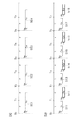
図5(a),(b)は、マーク検出信号とは無関係に画像形成タイミング(潜像形成開始のタイミング)を決定する方法を示すタイミングチャートである。図5(a)は、記録材の長手方向寸法が中間転写ベルト117の全周の1/2周以上である場合、すなわち、中間転写ベルト117上に1枚の記録材に対応する画像を形成する場合を示し、図5(b)は、記録材の長手方向寸法が中間転写ベルト117の全周の1/2を下回る長さである場合、すなわち、中間転写ベルト117上に2枚の記録材に対応する画像を一度に形成する場合を示している。
FIGS. 5A and 5B are timing charts showing a method of determining the image formation timing (latent image formation start timing) irrespective of the mark detection signal. 5A shows a case where the longitudinal dimension of the recording material is ½ or more of the entire circumference of the
この方法においては、CPU841は、任意のタイミングT0を起点として、マークセンサ301がHPマーク302又は303を検出する周期(τ)と同じ時間を計測するタイマを起動する。第1色目(Ya)の潜像形成は、この起点となるタイミングT0から一定時間(ta)後に行う。CPU841は、時間τが経過したことをタイマにより検出したら(このタイミングをT1とする)、更に同じ時間τを計測するタイマを起動する。この際、CPU841は、図5(a)の場合であれば、何もしないが、図5(b)の場合であれば、T1から一定時間(tb)後に2枚目の画像の第1色目(Yb)の潜像形成を開始する。
In this method, the
このように、マークセンサ301がHPマーク302又は303を検出する周期と同じ時間(τ)が経過する毎に、順次、上記の周期と同じ時間(τ)を計測するタイマを起動し、このタイマがタイムアップした時点から一定時間(ta又はtb)後に1枚目又は2枚目の各色の潜像形成を開始するという制御を繰り返すことによって、各色の1枚目のトナー画像511,513,515,517、2枚目のトナー画像512,514,516,518を、中間転写ベルト117上に重ね合わせて1次転写するようにしている。
In this way, whenever the same time (τ) as the period in which the
なお、本実施の形態では、低コスト化を図るため、タイマとしては、ROM843に格納されたプログラムにて所定時間を計測するソフトウェアタイマを想定しているが、より高精度に時間を計測するためには、CPU841の外部ユニットとして構成されたタイマを用いてもよく、また、ASIC等による専用ハードウェアで実現されたタイマを用いてもよい。
In this embodiment, in order to reduce the cost, a software timer that measures a predetermined time with a program stored in the
また、潜像形成開始タイミングをマーク検出信号に基づいて決定する場合、タイマに基づいて決定する場合の何れにおいても、記録材の長手方向寸法が中間転写ベルト117の全周の1/2を下回る長さである場合であっても、2枚分(2面分)の画像を同時に形成する必要がない場合(又はできない場合)には、記録材の長手方向寸法が中間転写ベルト117の全周の1/2周以上である場合と同じ方法で画像形成を行う。
Further, in both cases where the latent image formation start timing is determined based on the mark detection signal and when determined based on the timer, the longitudinal dimension of the recording material is less than ½ of the entire circumference of the
さらに、潜像形成開始タイミングをタイマに基づいて決定する方式としては、図5(a),(b)に示した方式以外の各種の方式を用いることができる。例えば、図7に示したように、任意のタイミングT0を起点として、それぞれ時間nτ(n=1〜8)を計測する複数のタイマを一斉に起動して画像形成開始タイミングを決定することも可能である。 Furthermore, as a method for determining the latent image formation start timing based on a timer, various methods other than the methods shown in FIGS. 5A and 5B can be used. For example, as shown in FIG. 7, it is also possible to start a plurality of timers each measuring time nτ (n = 1 to 8) starting from an arbitrary timing T0 and determine the image formation start timing. It is.
また、図8に示したように、それぞれ時間nτ(n=1〜2)を計測する2つのタイマを用意し、これら2つのタイマを中間転写ベルト117の1回転中に4回ずつ起動することによって画像形成開始タイミングを決定することも可能である。
Also, as shown in FIG. 8, two timers for measuring time nτ (n = 1 to 2) are prepared, and these two timers are started four times during one rotation of the
図5(a),(b)、図7、図8に示したようなタイマに基づく画像形成タイミングの制御方法では、起点となるタイミングT0を中間転写ベルト117用のモータの回転が安定した直後のタイミングに設定することにより、記録材に対する画像形成を迅速に行なうことが可能となる。
In the method of controlling the image formation timing based on the timer as shown in FIGS. 5A, 5B, 7 and 8, the start timing T0 is immediately after the rotation of the motor for the
図6は、操作部860上のユーザモードキー(図示省略)を押下することで表示パネルに表示されるユーザモード画面の1つを示している。図6に示したユーザモード画面600では、画像形成開始タイミングをマーク検出信号に基づいて制御するか、或いはタイマに基づいて制御するかを選択することができる。なお、ユーザモード画面とは、画像形成装置100が有する各種の機能毎の動作設定を行うためのユーザインタフェース画面のことである。
FIG. 6 shows one of user mode screens displayed on the display panel when a user mode key (not shown) on the
図6に示したユーザモード画面600において、ONボタン601を押下した場合、すなわちユーザがコピー出力時間短縮モードを選択した場合には、図5(a),(b)、図7、図8に示したように、画像形成開始タイミングがタイマに基づいて制御され、早期に画像形成動作が開始される。一方、OFFボタン602を押下した場合には、図4に示したように、画像形成開始タイミングがマーク検出信号に基づいて制御される。
When the user presses the
なお、ユーザモード画面600上でユーザがONボタン601、OFFボタン602の何れのボタンも押下されていない場合、すなわち、コピー出力時間がデフォルトの状態では、マーク検出信号に基づいて画像形成開始タイミングが制御される。また、タイマに基づく画像形成開始タイミングの制御方式は、画像形成動作を早期に開始するためだけでなく、画像形成装置100内の汚れ等によりマークセンサ301がHPマーク302、303を正常に読取れなくなったような場合や、ノイズによりマーク検出信号が異常を示すような場合に、自動的に切り替えて、対処しても活用できる。
When the user does not press any of the
本発明は、上記の実施の形態に限定されることなく、例えば、2枚の記録材に記録する2つの画像を同時に感光体及び中間転写ベルト上に形成する場合だけでなく、1枚の記録材の表裏両面に記録する2つの画像を同時に感光体及び中間転写ベルト上に形成する場合にも、上記の実施の形態に係る手法を適用することが可能である。 The present invention is not limited to the above-described embodiment. For example, the present invention is not limited to the case where two images to be recorded on two recording materials are simultaneously formed on the photosensitive member and the intermediate transfer belt. The method according to the above embodiment can also be applied to the case where two images to be recorded on both the front and back surfaces of the material are simultaneously formed on the photoreceptor and the intermediate transfer belt.
また、本発明の目的は、実施形態の機能を実現するソフトウェアのプログラムコードを記録した記憶媒体を、システム或いは装置に供給し、そのシステム或いは装置のコンピュータ(またはCPUやMPU等)が記憶媒体に格納されたプログラムコードを読み出して実行することによっても達成される。 In addition, an object of the present invention is to supply a storage medium storing software program codes for realizing the functions of the embodiments to a system or apparatus, and a computer (or CPU, MPU, etc.) of the system or apparatus as a storage medium. This can also be achieved by reading and executing the stored program code.
この場合、記憶媒体から読み出されたプログラムコード自体が前述した実施の形態の機能を実現することになり、そのプログラムコード及び該プログラムコードを記憶した記憶媒体は本発明を構成することになる。 In this case, the program code itself read from the storage medium realizes the functions of the above-described embodiments, and the program code and the storage medium storing the program code constitute the present invention.
又、プログラムコードを供給するための記憶媒体としては、例えば、フロッピー(登録商標)ディスク、ハードディスク、光磁気ディスク、CD−ROM、CD−R、CD−RW、DVD−ROM、DVD−RAM、DVD−RW、DVD+RW、磁気テープ、不揮発性のメモリカード、ROM等を用いることができる。または、プログラムコードをネットワークを介してダウンロードしてもよい。 Examples of the storage medium for supplying the program code include a floppy (registered trademark) disk, a hard disk, a magneto-optical disk, a CD-ROM, a CD-R, a CD-RW, a DVD-ROM, a DVD-RAM, and a DVD. -RW, DVD + RW, magnetic tape, nonvolatile memory card, ROM, etc. can be used. Alternatively, the program code may be downloaded via a network.
また、コンピュータが読み出したプログラムコードを実行することにより、上記実施の形態の機能が実現されるだけでなく、そのプログラムコードの指示に基づき、コンピュータ上で稼動しているOS(オペレーティングシステム)等が実際の処理の一部または全部を行い、その処理によって前述した実施形態の機能が実現される場合も含まれる。 Further, by executing the program code read by the computer, not only the functions of the above-described embodiments are realized, but also an OS (operating system) running on the computer based on the instruction of the program code. A case where part or all of the actual processing is performed and the functions of the above-described embodiments are realized by the processing is also included.
更に、記憶媒体から読み出されたプログラムコードが、コンピュータに挿入された機能拡張ボードやコンピュータに接続された機能拡張ユニットに備わるメモリに書き込まれた後、そのプログラムコードの指示に基づき、その機能拡張ボードや機能拡張ユニットに備わるCPU等が実際の処理の一部または全部を行い、その処理によって前述した実施形態の機能が実現される場合も含まれる。 Further, after the program code read from the storage medium is written in a memory provided in a function expansion board inserted into the computer or a function expansion unit connected to the computer, the function expansion is performed based on the instruction of the program code. This includes the case where the CPU or the like provided in the board or the function expansion unit performs part or all of the actual processing, and the functions of the above-described embodiments are realized by the processing.
111…感光体ドラム
117…中間転写ベルト
301…マークセンサ
302,303…HPマーク
840…プリンタ制御部
841…CPU
843…ROM
844…RAM
848…露光制御部
860…操作部
111 ...
843 ... ROM
844 ... RAM
848 ...
Claims (8)
前記中間転写体上の前記マークを検出する検出手段と、
前記検出手段による前記マークの検出タイミングに基づいて画像形成タイミングを制御する第1の制御手段と、
前記中間転写体の回転状態が安定したタイミングから所定の時間を計時する計時手段と、
前記計時手段による前記時間の計時アップのタイミングに基づいて画像形成タイミングを制御する第2の制御手段と、
前記第1の制御手段による画像形成タイミングの制御と前記第2の制御手段による画像形成タイミングの制御を切替える切替手段と、
を有することを特徴とする画像形成装置。 An intermediate transfer member for transferring the developed image on the image carrier, and a rotatable intermediate transfer member having a mark indicating a reference position of the intermediate transfer member;
Detecting means for detecting the mark on the intermediate transfer member;
First control means for controlling image formation timing based on the detection timing of the mark by the detection means;
A time measuring means for measuring a predetermined time from a timing when the rotation state of the intermediate transfer member is stable;
Second control means for controlling the image formation timing based on the timing of timing up of the time by the time measuring means;
Switching means for switching between control of image formation timing by the first control means and control of image formation timing by the second control means;
An image forming apparatus comprising:
前記中間転写体上の前記マークを検出する検出工程と、
前記検出工程による前記マークの検出タイミングに基づいて画像形成タイミングを制御する第1の制御工程と、
前記中間転写体の回転状態が安定したタイミングから所定の時間を計時する計時工程と、
前記計時工程による前記時間の計時アップのタイミングに基づいて画像形成タイミングを制御する第2の制御工程と、
前記第1の制御工程による画像形成タイミングの制御と前記第2の制御工程による画像形成タイミングの制御を切替える切替工程と、
を有することを特徴とする制御方法。 A control method for an image forming apparatus having an intermediate transfer member for transferring a developed image on an image carrier and having a rotatable intermediate transfer member having a mark indicating a reference position of the intermediate transfer member,
A detection step of detecting the mark on the intermediate transfer member;
A first control step of controlling image formation timing based on the detection timing of the mark by the detection step;
A time measuring step for measuring a predetermined time from the timing when the rotation state of the intermediate transfer member is stable;
A second control step of controlling the image formation timing based on the timing of timing up of the time by the timing step;
A switching step of switching between image formation timing control by the first control step and image formation timing control by the second control step;
A control method characterized by comprising:
Priority Applications (2)
| Application Number | Priority Date | Filing Date | Title |
|---|---|---|---|
| JP2005203634A JP2007024996A (en) | 2005-07-12 | 2005-07-12 | Image forming apparatus, control method, and program |
| US11/456,683 US7495683B2 (en) | 2005-07-12 | 2006-07-11 | Image forming apparatus and control method therefor |
Applications Claiming Priority (1)
| Application Number | Priority Date | Filing Date | Title |
|---|---|---|---|
| JP2005203634A JP2007024996A (en) | 2005-07-12 | 2005-07-12 | Image forming apparatus, control method, and program |
Publications (2)
| Publication Number | Publication Date |
|---|---|
| JP2007024996A true JP2007024996A (en) | 2007-02-01 |
| JP2007024996A5 JP2007024996A5 (en) | 2008-02-21 |
Family
ID=37785884
Family Applications (1)
| Application Number | Title | Priority Date | Filing Date |
|---|---|---|---|
| JP2005203634A Pending JP2007024996A (en) | 2005-07-12 | 2005-07-12 | Image forming apparatus, control method, and program |
Country Status (1)
| Country | Link |
|---|---|
| JP (1) | JP2007024996A (en) |
Cited By (3)
| Publication number | Priority date | Publication date | Assignee | Title |
|---|---|---|---|---|
| JP2011133861A (en) * | 2009-11-30 | 2011-07-07 | Canon Inc | Image forming apparatus |
| KR101239153B1 (en) | 2009-03-26 | 2013-03-06 | 캐논 가부시끼가이샤 | Image forming apparatus and image forming method |
| US8606134B2 (en) | 2010-08-20 | 2013-12-10 | Canon Kabushiki Kaisha | Image forming apparatus |
Citations (5)
| Publication number | Priority date | Publication date | Assignee | Title |
|---|---|---|---|---|
| JP2000039813A (en) * | 1998-07-23 | 2000-02-08 | Ricoh Co Ltd | Image forming device |
| JP2001343878A (en) * | 2000-05-31 | 2001-12-14 | Canon Inc | Image forming device |
| JP2003195604A (en) * | 2001-12-28 | 2003-07-09 | Konica Corp | Color image forming apparatus and registration method for the color image forming apparatus |
| JP2004240306A (en) * | 2003-02-07 | 2004-08-26 | Canon Inc | Image forming apparatus and image forming control method |
| JP2005178080A (en) * | 2003-12-17 | 2005-07-07 | Ricoh Co Ltd | Color image forming device |
-
2005
- 2005-07-12 JP JP2005203634A patent/JP2007024996A/en active Pending
Patent Citations (5)
| Publication number | Priority date | Publication date | Assignee | Title |
|---|---|---|---|---|
| JP2000039813A (en) * | 1998-07-23 | 2000-02-08 | Ricoh Co Ltd | Image forming device |
| JP2001343878A (en) * | 2000-05-31 | 2001-12-14 | Canon Inc | Image forming device |
| JP2003195604A (en) * | 2001-12-28 | 2003-07-09 | Konica Corp | Color image forming apparatus and registration method for the color image forming apparatus |
| JP2004240306A (en) * | 2003-02-07 | 2004-08-26 | Canon Inc | Image forming apparatus and image forming control method |
| JP2005178080A (en) * | 2003-12-17 | 2005-07-07 | Ricoh Co Ltd | Color image forming device |
Cited By (3)
| Publication number | Priority date | Publication date | Assignee | Title |
|---|---|---|---|---|
| KR101239153B1 (en) | 2009-03-26 | 2013-03-06 | 캐논 가부시끼가이샤 | Image forming apparatus and image forming method |
| JP2011133861A (en) * | 2009-11-30 | 2011-07-07 | Canon Inc | Image forming apparatus |
| US8606134B2 (en) | 2010-08-20 | 2013-12-10 | Canon Kabushiki Kaisha | Image forming apparatus |
Similar Documents
| Publication | Publication Date | Title |
|---|---|---|
| JP4933160B2 (en) | Image forming system, image forming apparatus, clear image forming apparatus, and control apparatus | |
| US6763202B2 (en) | Image forming apparatus | |
| JP2008145595A (en) | Image forming system, and transparent image forming apparatus and control method for it | |
| JP2007322818A (en) | Image forming system | |
| US7495683B2 (en) | Image forming apparatus and control method therefor | |
| JP2008152106A (en) | Image forming apparatus | |
| JP2004004622A (en) | Image forming apparatus and form setting control method | |
| JP2009297917A (en) | Exposure control unit and its processing method, image forming apparatus, and program | |
| JP2007024996A (en) | Image forming apparatus, control method, and program | |
| JP3962694B2 (en) | Image forming apparatus and image forming control method | |
| JP2006194963A (en) | Image forming apparatus | |
| JP2008145453A (en) | Image forming system and image forming apparatus | |
| JP2011059325A (en) | Image forming apparatus and method for controlling the same | |
| JP2007286108A (en) | Image processor | |
| JP4323234B2 (en) | Image forming apparatus | |
| JP4819417B2 (en) | Image forming apparatus | |
| JPH096066A (en) | Method for forming image and device therefor | |
| JP3721769B2 (en) | Image forming apparatus | |
| JP2004294855A (en) | Image forming apparatus | |
| JP4310129B2 (en) | Document feeding apparatus, image forming apparatus, method for controlling document feeding apparatus, and method for controlling image forming apparatus | |
| JP2004090457A (en) | Calibration method and printer | |
| JP2007127963A (en) | Image forming apparatus | |
| JP2003118881A (en) | Image forming device | |
| JP2006162745A (en) | Image forming apparatus | |
| JP2005164922A (en) | Image forming apparatus |
Legal Events
| Date | Code | Title | Description |
|---|---|---|---|
| RD05 | Notification of revocation of power of attorney |
Free format text: JAPANESE INTERMEDIATE CODE: A7425 Effective date: 20070626 |
|
| A521 | Written amendment |
Free format text: JAPANESE INTERMEDIATE CODE: A523 Effective date: 20071225 |
|
| A621 | Written request for application examination |
Free format text: JAPANESE INTERMEDIATE CODE: A621 Effective date: 20071225 |
|
| A977 | Report on retrieval |
Free format text: JAPANESE INTERMEDIATE CODE: A971007 Effective date: 20100809 |
|
| A131 | Notification of reasons for refusal |
Free format text: JAPANESE INTERMEDIATE CODE: A131 Effective date: 20100817 |
|
| A02 | Decision of refusal |
Free format text: JAPANESE INTERMEDIATE CODE: A02 Effective date: 20110105 |