JP2007018427A - Print system - Google Patents
Print system Download PDFInfo
- Publication number
- JP2007018427A JP2007018427A JP2005201615A JP2005201615A JP2007018427A JP 2007018427 A JP2007018427 A JP 2007018427A JP 2005201615 A JP2005201615 A JP 2005201615A JP 2005201615 A JP2005201615 A JP 2005201615A JP 2007018427 A JP2007018427 A JP 2007018427A
- Authority
- JP
- Japan
- Prior art keywords
- printing
- image information
- procedure
- image data
- Prior art date
- Legal status (The legal status is an assumption and is not a legal conclusion. Google has not performed a legal analysis and makes no representation as to the accuracy of the status listed.)
- Withdrawn
Links
Images


Abstract
Description
本発明は熱転写式プリンタと印刷情報出力を無線により接続して印刷を行うプリントシステムに関し、より具体的には静止画を記録するスチルカメラやビデオカメラなどによって撮像された電子情報を、印刷出力するのに好適なプリントシステムに関するものである。 The present invention relates to a printing system that wirelessly connects a thermal transfer printer and print information output, and more specifically, prints out electronic information captured by a still camera, a video camera, or the like that records a still image. The present invention relates to a printing system suitable for the above.
従来から印画用紙に感熱型の用紙を用い、主走査方向に配列された複数個の発熱体を選択的に駆動して、用紙を副走査方向に搬送することで、用紙にドットライン状に印画を行うライン熱転写方式のプリンタがある。 Conventionally, heat-sensitive paper has been used as printing paper, and a plurality of heating elements arranged in the main scanning direction are selectively driven to convey the paper in the sub-scanning direction, thereby printing dots on the paper. There is a line thermal transfer type printer that performs this.
近年、入力側としてのデジタルカメラやデジタルビデオカメラ、またはスキャナなどの画像を扱う入力機器の進歩に伴い、プリント手段として、熱転写方式のプリンタ装置も注目されている。 In recent years, with the progress of input devices that handle images such as digital cameras, digital video cameras, and scanners on the input side, thermal transfer type printer apparatuses have attracted attention as printing means.
それはインクジェットプリンターが、液滴を飛ばすか飛ばさないか、という2値の選択しかないために、小さな液滴を用紙へ着弾させて、誤差拡散等の手法でみかけの解像度と階調性を得ようとするのに対して、熱転写方式のプリンタの場合には、一つの画素において、制御可能な熱の値を容易に変更できるため、一つの画素に対する階調性が多く取る事が可能になるので、インクジェットプリンターに比べて滑らかで高画質な画像を得ることができるという点が上げられる。 Because the inkjet printer has only two choices of whether or not to drop the droplets, let the small droplets land on the paper and get an apparent resolution and gradation by methods such as error diffusion On the other hand, in the case of a thermal transfer printer, the controllable heat value can be easily changed in one pixel, so that a large gradation can be obtained for one pixel. As a result, it is possible to obtain a smoother and higher quality image as compared with the ink jet printer.
またサーマルヘッドの性能や用紙材料の性能も向上したために、仕上がり品位で銀塩写真にも見劣りしない画像プリントを得る事が可能になっており、近年のデジタルカメラの進歩に歩調を合わせるように特に自然画像用のプリンタとして注目されている。 In addition, the performance of the thermal head and the performance of paper materials have also improved, making it possible to obtain image prints that are as good as silver halide photographs with a finished quality, especially in order to keep pace with the recent progress of digital cameras. It is attracting attention as a printer for natural images.
また一方インクジェット式プリンタも液滴の小ドット化などの技術が進み、より高画質なものも登場している。 On the other hand, ink-jet printers have been developed with technology such as smaller droplets, and more high-quality printers have also appeared.
そこでこうしたプリンタ装置とデジタルカメラやデジタルビデオカメラなどの撮影機器を直接的に接続したり、または一体的に構成して、撮影された画像情報をコンピューターなどの画像情報を処理する機器を介すことなくプリントするシステムも登場している。 Therefore, such a printer device is directly connected to a photographing device such as a digital camera or a digital video camera, or it is configured integrally and the photographed image information is passed through a device such as a computer for processing the image information. There is also a system for printing.
こうしたシステムによれば、デジタルカメラやデジタルビデオからの画像情報を簡単に写真的なプリントアウトを行うことが可能になり、大変便利である。 According to such a system, it is possible to easily print out image information from a digital camera or digital video, which is very convenient.
これらの一例として、特許文献1では画像プリントシステムについて提案されている。
しかしながら、上記従来例ではプリンタ装置や、デジタルカメラなどの画像入力機器とのシステムを構成したときに十分な小型化や、低コスト、高速化等に十分な解決方法を与えるものではなかった。 However, in the above conventional example, when a system with a printer device or an image input device such as a digital camera is configured, a sufficient solution for miniaturization, low cost and high speed is not provided.
例えば熱転写によるプリンタとデジタルカメラなどの画像入力機器を無線接続して高速印刷を実現するためには印刷画像データを受信に平行して印刷用紙の印刷開始位置への移動、熱転写印刷用のインクリボンの先頭位置検出などの印刷準備を行っておいた方が印刷時間を短くするのに有効である。しかしながら熱転写によるプリンタとデジタルカメラなどの画像入力機器を無線により接続した場合、印刷画像データ通信中の伝送経路の状況により印刷画像データの受信が完了しないと言った伝送事故が容易に発生する恐れがある。 For example, to achieve high-speed printing by wirelessly connecting a thermal transfer printer and an image input device such as a digital camera, move the print paper to the print start position in parallel with receiving the print image data, and an ink ribbon for thermal transfer printing. It is effective to shorten the printing time by preparing for printing such as detecting the leading position of the. However, when a printer using thermal transfer and an image input device such as a digital camera are connected wirelessly, there is a risk that a transmission accident that reception of print image data is not completed due to the condition of the transmission path during print image data communication may easily occur. is there.
この様な伝送事故を印刷失敗として処理した場合、一般の熱転写プリンタでは印刷準備状態にあったインクリボンを印刷待機状態に巻き戻す動作は行わないので、次回印刷時には新たにインクリボンの先頭検出動作を行うためにインクリボンを未使用のまま巻き取ってしまいインクリボンを1印刷分無駄にしてしまうと言った問題点があった。 When such a transmission accident is handled as a printing failure, an ordinary thermal transfer printer does not rewind the ink ribbon that was in the print ready state to the print standby state. In order to perform this, there is a problem that the ink ribbon is wound up unused and the ink ribbon is wasted for one printing.
本発明は以上の様な問題点を考慮したプリントシステムであって、画像入力機器と熱転写プリンタを無線接続したプリントシステムに於いて高速印刷を実現し、インクリボンの無駄を防ぐプリントシステムを提供することを目的とする。 The present invention provides a printing system that takes into account the above-described problems and realizes high-speed printing in a printing system in which an image input device and a thermal transfer printer are wirelessly connected and prevents waste of an ink ribbon. For the purpose.
印刷画像情報送信手段と印刷画像受信手段、印刷画像情報受信成否統計手段、印刷手順判定手段、印刷機構駆動手段から構成されるプリントシステム。 A printing system comprising a print image information transmitting unit, a print image receiving unit, a print image information reception success / failure statistical unit, a printing procedure determining unit, and a printing mechanism driving unit.
すなわち、本発明の技術内容は以下の構成を備えることにより前記課題を解決できた。 That is, the technical contents of the present invention can solve the above-described problems by including the following configuration.
(1)印刷画像情報を無線により送信する画像情報送信手段と画像情報を受信する画像情報受信手段と受信した画像画像情報より印画を行う印画手段と、画像情報受信の成否を統計記録する記録手段と、印画の手順を決定する印画手順決定手段とから構成され、画像情報通信の成否の統計により印刷手順を変えることを特徴とするプリントシステム。 (1) Image information transmitting means for wirelessly transmitting print image information, image information receiving means for receiving image information, printing means for performing printing from the received image image information, and recording means for statistically recording success or failure of image information reception And a printing procedure determining means for determining a printing procedure, and the printing procedure is changed according to statistics of success or failure of image information communication.
本発明によれば、印刷画像情報受信失敗時に印刷消耗材の無駄を可能な限り防ぎながら、同時に高速での印刷動作を可能にする。 According to the present invention, it is possible to simultaneously perform a high-speed printing operation while preventing waste of printing consumable materials as much as possible when printing image information reception fails.
以下本発明を実施するための最良の形態を、実施例により詳しく説明する。 Hereinafter, the best mode for carrying out the present invention will be described in detail with reference to examples.
図1から図4に示す図を用いて本発明の実施例について説明する。 Embodiments of the present invention will be described with reference to FIGS.
本プリントシステムは、プリンタ部に昇華型の熱転写記録方式を採用し、電子的な画像の情報を任意なプリント枚数分プリントアウトすることが出来るものである。本発明に係わる通常の熱転写記録装置の一実施形態について、以下、図面を参照して具体的に説明する。 This printing system employs a sublimation type thermal transfer recording system in a printer unit, and can print out electronic image information for an arbitrary number of prints. An embodiment of a normal thermal transfer recording apparatus according to the present invention will be specifically described below with reference to the drawings.
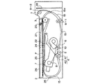
図1は実施形態に係わる記録装置の側面の構成模式図である。 FIG. 1 is a schematic configuration diagram of a side surface of a recording apparatus according to an embodiment.
まず、記録装置の全体構成について説明すると、装置本体1に記録紙Pを積載した用紙カセット2から給紙ローラ3で一枚ずつ分離給送する。この際記録紙Pはバネ20によって付勢された押上げ板21によって給紙ローラ3に当接している。そして、給紙ローラ3によって搬送された記録紙Pは搬送ローラ対4で挟持搬送されて記録部を往復可能にしている。搬送ローラ対4はピンチローラ42とグリップローラ41で構成されている。
First, the overall configuration of the recording apparatus will be described. A sheet feeding roller 3 separates and feeds sheets one by one from a
記録部においては記録紙搬送経路を挟んでプラテンローラ5と記録情報に応じて発熱するサーマルヘッド6が対向しており、インクカセット7に収納される、熱溶融性または熱昇華性インクを塗布したインク層と印画面を保護するために印画面上にオーバーコートされるオーバーコート層をもつインクシート8をサーマルヘッド6によって記録紙Pに押圧するとともに、選択的に加熱することにより、該記録紙Pに所定画像を転写記録し、保護層をオーバーコートする。
In the recording section, the
上記インクシートは、記録紙Pの印画領域を覆ってそのサイズと略等しいサイズでイエロー(Y)、マゼンタ(M)、シアン(C)の各インク層とオーバーコート(OP)層が並べて設けられたものであり、各層ずつ熱転写しては、記録紙Pを記録開始位置P1に戻し、記録紙上に、順次重ねて転写される。このように、記録紙Pは搬送ローラ対4により、各色インク及びオーバーコート層の数だけ往復される。 The ink sheet covers the print area of the recording paper P and is provided with a yellow (Y), magenta (M), and cyan (C) ink layer and an overcoat (OP) layer arranged in a size substantially equal to the size. After each layer is thermally transferred, the recording paper P is returned to the recording start position P1 and transferred onto the recording paper one after another. In this way, the recording paper P is reciprocated by the number of inks of each color and the number of overcoat layers by the conveying roller pair 4.
この際、各インク層の印画後の記録紙Pは装置本体1前方で反転され、用紙カセット前方部及び下部のガイド部を介して装置本体1の後方へ導紙される。装置前方で反転されるために印画途中の記録紙Pが外部に出ることによるスペースの無駄や意図せずに触ってしまったという様なことが無く、設置場所の省スペース化などを可能にしている。しかも用紙カセット2の下部を紙ガイドとして直接利用していることによって装置本体1の厚さを薄くすることが可能になっていると共に、記録紙Pをインクカセット7と用紙カセット2にはさまれた空間を通すことで装置本体1の全高を最小限にとどめることが可能であり小型化を可能にしている。
At this time, the recording paper P after printing of each ink layer is reversed in front of the apparatus
25は用紙カセット2の用紙搬送ガイド部である。装置本体1前方から反転されてきた記録紙Pを装置本体後方に反転させるガイド部であり、この用紙カセット2に具備することで装置本体1全体の小型化に大きく寄与している。
また26は用紙カセット2の上面は印画されて排紙された記録紙Pのトレイ部分を兼用しており、これも装置本体1の小型化に寄与している。各インク層の印画終了後に記録紙Pは排紙ローラ1 9−1、排出ローラ2 9−2へ案内され装置本体1後方から前方に向かって排出され記録動作が終了する。排出ローラ1 9−1は記録紙Pの排出動作時のみ圧接する様に構成され、印画中にはストレスがかからないように構成されている。なお装置本体1には記録紙Pのガイド部15が構成されていて、記録紙Pを導紙している。
15aは搬送路切り替えシートであり、記録紙Pが給紙された後は記録紙Pは排出側の経路に導紙されるようになっている。 Reference numeral 15a denotes a conveyance path switching sheet. After the recording paper P is fed, the recording paper P is guided to the discharge-side path.
また印画用のサーマルヘッド6はヘッドアーム22に一体的に具備されており、インクカセット7を交換する場合にはインクカセット7の抜き差しに支障ない位置まで退避する。この退避動作はインクカセット7の交換は用紙カセット2を引き抜くと可能になり、この際用紙カセット2の着脱動作に連動してヘッドアーム22はカム部(不図示)によって押さえられている状態から用紙カセット2のカム部が退避していくことで上下する様に構成されている。
Further, the
通常の熱転写記録装置ではYMC3色を3回面順次で記録する為、各色の記録先端を正確に合致させる制御が必要となる。このためには、図1に示す搬送ローラ対4で記録紙Pを離さずしっかり挟持し搬送を行う必要がある。この為、記録紙Pの送り方向の端部には記録不可能な余白部が必要となる。これを鑑み、最終的に、容易に、縁のない印画物を得るために、図3に示す様に、記録紙Pには、記録開始時搬送ローラ対4でしっかり挟持され記録できない余白部分を後で容易に手で切取り可能な様にミシン目12が設けられる。
In a normal thermal transfer recording apparatus, three colors of YMC are recorded three times in a surface sequential manner, so that it is necessary to control to accurately match the recording leading ends of the respective colors. For this purpose, it is necessary to convey the recording paper P firmly between the conveying roller pair 4 shown in FIG. For this reason, an unrecordable blank portion is required at the end of the recording paper P in the feed direction. In view of this, finally, in order to easily obtain a print having no border, as shown in FIG. 3, the recording paper P has a blank portion that is firmly sandwiched by the conveying roller pair 4 at the start of recording and cannot be recorded. A
本発明は、上記説明したミシン目をもつ記録紙Pと熱転写記録装置をもちいて実施され、上記の記録紙に設けられたミシン目領域にはオーバーコートするものとする。また左下がり斜線で示す領域は印画の領域であり、ミシン目を含む領域を印画する様に制御される。オーバーコートは略印画される領域であり且つ印画される領域よりやや大きく印画される領域を含むように印画する様に制御される。 The present invention is implemented using the recording paper P having the perforations described above and the thermal transfer recording apparatus, and the perforation region provided on the recording paper is overcoated. The area indicated by the diagonally slanting left line is a printing area, and is controlled so as to print an area including a perforation. The overcoat is an area that is substantially printed and is controlled so as to include an area that is printed slightly larger than the area to be printed.
更に以下に装置に関わる詳しい説明をする。 Furthermore, the detailed description regarding an apparatus is given below.
図1に示す、記録装置1において、搬送ローラ対4は、ピンチローラ42とグリップローラ41からなり、このグリップローラ41は、図示しないステッピングモータの出力軸が減速機構を介してして直結され、このステッピングモータの回転制御により、正逆自在に駆動される。記録紙Pは、搬送ローラ対4によりしっかりと挟持され、往復搬送されるもであるから、記録紙Pもまた、ステッピングモータの回転制御により、正確に位置制御され、搬送駆動される。
In the
いま、一例としてサーマルヘッド6による1ライン分の記録ピッチを85μmとし、記録紙Pを1ライン分搬送するためのステッピングモータのステップ数を4ステップとするならば、記録紙Pは、ステッピングモータを4ステップで回転制御することにより、1ライン(すなわち85μm)搬送することができる。
As an example, if the recording pitch for one line by the
図3に示した、印画範囲は、搬送方向において144mmであるとすると、1694ライン印画可能であり、記録紙をこの分搬送するためには、ステッピングモータを6776ステップ分回転させればよい。 If the printing range shown in FIG. 3 is 144 mm in the transport direction, 1694 lines can be printed, and in order to transport the recording paper by this amount, the stepping motor may be rotated by 6776 steps.
図1に示す、記録装置1において、給紙ローラ3から給紙ローラ対4を見て、給紙ローラ対4の近傍の位置に、記録紙先端検出センサー10が置かれ、これにより記録紙の先端を検出し、検出後、搬送ローラ対4で挟持できる範囲で所定ラインを送り停止させる。この位置が前述の記録開始時の位置となる。ここからまず最初のYイエローからサーマルヘッドを記録情報に応じて発熱駆動し、各色インクの所定画像を記録し、またはオーバーコート層を転写する。1色が終わると次にこの位置から記録紙を排紙ローラ9のある方向に戻して搬送し、再び所定のライン数を戻し送り、YMC各色及びオーバーコート層転写を4回繰返す。
In the
図1に示す記録装置1において、記録紙先端検出センサー10と、プラテンローラ5とサーマルヘッド6により記録紙Pを押圧する位置の距離は、装置内部品配置を考慮し、記録紙上の距離で20mmに設定したがこれに限られるものでは無い。
In the
この時、図3に示す印画物は、下記の様に各色インクを転写記録し、またオーバーコート層を転写することにより得られる。 At this time, the printed matter shown in FIG. 3 is obtained by transferring and recording each color ink and transferring the overcoat layer as described below.
図2のフローチャートにおいて色インク転写及びオーバーコートシーケンスを説明する。 The color ink transfer and overcoat sequence will be described with reference to the flowchart of FIG.
S1:使用者は不図示のプリントボタンもしくはデジタルカメラやデジタルビデオカメラからの印画指示などによってプリント動作を指示する。 S1: The user instructs a print operation by a print button (not shown) or a print instruction from a digital camera or digital video camera.
S2:装置本体1装置本体1内部の処理回路18はプリント指示を実行した機器との通信を開始し、処理回路18ではプリント指示を実行した機器との間でプリントに必要な諸条件の確認や必要であれば画像情報の印画情報への画像処理を行う。
S2: Device
S3:印画準備が出来たら制御手段19は給紙ローラ3に連結されたモータを駆動して記録紙Pを給紙開始する。 S3: When preparation for printing is completed, the control means 19 drives the motor connected to the paper feed roller 3 to start feeding the recording paper P.
S4:記録紙先端検出後、ステッピングモータを所定ステップ分回転させ、印画を開始する。このとき、印画開始位置は、記録紙先端を基準として、12.465mmとした。 S4: After detecting the leading edge of the recording paper, the stepping motor is rotated by a predetermined step to start printing. At this time, the printing start position was set to 12.465 mm with reference to the leading edge of the recording paper.
S5:引き続き、ステッピングモータを4ステップ分回転しながら、サーマルヘッドを発熱駆動し1ライン分の印画を行う。全部で6776ステップ分(1694ライン分)回転させ、印画を終了する。この時の印画終了位置は、記録紙先端を基準として、156.455mmとなる。 S5: Subsequently, while the stepping motor is rotated by four steps, the thermal head is driven to generate heat, and printing for one line is performed. The printing is completed by rotating for a total of 6776 steps (1694 lines). The print end position at this time is 156.455 mm with reference to the leading edge of the recording paper.
S6:ついで、停止にいたるまでの減速のため、ステッピングモータを10ライン分(40ステップ分)程回転させ、停止させる。 S6: Next, the stepping motor is rotated by about 10 lines (40 steps) and stopped for deceleration until stopping.
S7:この状態から、ステッピングモータを逆転駆動し、記録紙Pを印画時と逆方向に搬送し、所定のステップ数(6776ステップ−減速分)だけ戻して、更に減速のため、所定のライン数の10ライン分(40ステップ分)程回転させ、停止させる。 S7: From this state, the stepping motor is driven in the reverse direction, the recording paper P is conveyed in the reverse direction to the time of printing, is returned by a predetermined number of steps (6776 steps-deceleration), and for further deceleration, the predetermined number of lines. Rotate about 10 lines (40 steps) and stop.
S8:上記をYMC3色分、3回程繰返し、所望の印画像を記録紙Pに転写記録する。 S8: The above is repeated three times for the three colors of YMC, and a desired mark image is transferred and recorded on the recording paper P.
S9:その後、そして、更に一回印画面保護の為のオーバーコート層を転写する。 S9: Thereafter, the overcoat layer for protecting the printing screen is transferred once more.
S10:その後ステッピングモータを逆転駆動してそのまま排出ローラ2 9−2へ導き、排出ローラ2 9−2の駆動で用紙を排出して一連の動作を終了させる。 S10: Thereafter, the stepping motor is driven in the reverse direction and guided to the discharge roller 29-2 as it is, and the sheet is discharged by driving the discharge roller 29-2 to end a series of operations.
また、上記において、制御手段(不図示)は記録紙Pの給紙時に、最初に記録紙先端検出センサ10で検知した記録紙の先端検出信号をもとに、ステッピングモータのステップ数と記録紙Pの搬送時における位置関係をもとに、ステッピングモータの回転駆動のステップ数を、全印画記録時において管理することにより、記録位置管理を行うとしたが、これにかぎらす、各YMC色及びオーバーコート層の転写記録時において、記録紙先端部に検出センサーを設けて記録紙の先端検出を行い、その信号を基準として、ステッピングモータの回転駆動のステップ数を管理することにより、記録位置管理を行う構成としても良い。
In the above description, the control means (not shown) determines the number of steps of the stepping motor and the recording paper based on the recording paper leading edge detection signal first detected by the recording paper leading
また、上記において、オーバーコート層の転写は、サーマルヘッドの発熱駆動のON/OFFのみで行う様に記述したが、オーバーコートの転写開始時では、徐々に発熱量を増加させ、また、オーバーコートの転写終了時には、徐々に発熱量を減少させることにより得る様な制御を加える事も可能である。 In the above description, the transfer of the overcoat layer is described to be performed only by turning ON / OFF the heat generation drive of the thermal head. However, at the start of the overcoat transfer, the heat generation amount is gradually increased, and the overcoat layer is transferred. At the end of the transfer, it is also possible to add a control as obtained by gradually reducing the amount of heat generation.
ここで前述のS2のプリント指示を実行する機器と、該プリンター装置の通信について更に詳述する。 Here, communication between the apparatus that executes the above-described print instruction of S2 and the printer apparatus will be described in more detail.
一例として、プリント指示を実行するのはデジタルカメラDCとして説明する。 As an example, it is assumed that the print instruction is executed as a digital camera DC.
図4はデジタルカメラDCとプリンタ装置本体1を802.11b、ブルートゥース、IrDAなどに代表される無線手段による接続がなされる模式図である。
FIG. 4 is a schematic diagram in which the digital camera DC and the printer apparatus
デジタルカメラDCは撮影後に該デジタルカメラDC内部のメモリに画像情報が保持されているものとする。メモリはコンパクトフラッシュ(登録商標)カードやスマートメディア(登録商標)といった着脱自由なものが便利である。デジタルカメラDCのモードを設定して、任意の画像を再生させるものとする。 It is assumed that the digital camera DC holds image information in a memory inside the digital camera DC after shooting. As the memory, a removable memory such as a compact flash (registered trademark) card or smart media (registered trademark) is convenient. It is assumed that an arbitrary image is reproduced by setting a mode of the digital camera DC.
画像情報の再生はデジタルカメラDCの具備する液晶表示装置によって随時確認できるので使用者は撮影された好きな画像情報を任意に呼び出すことが可能である。ここで無線手段によってプリンタ装置本体1と通信可能な状態であると、所定のプリント実行ボタン(図不示)によってデジタルカメラDCからプリンタ装置へ必要な情報が通信され、プリンタ装置本体1からプリント出力が得られるというものである。
Since the reproduction of the image information can be confirmed at any time by the liquid crystal display device included in the digital camera DC, the user can arbitrarily call the photographed favorite image information. If the wireless device can communicate with the printer apparatus
上記必要な情報としては、デジタルカメラDCとのネゴシエーションの情報や、デジタルカメラDCからのプリントすべき画像の情報や画像情報に記録時または記録後から付加された情報、等である。 The necessary information includes information on negotiation with the digital camera DC, information on an image to be printed from the digital camera DC, information added to the image information at or after recording, and the like.
一般的に印刷画像が大きい場合、デジタルカメラDCとプリンタ装置本体1との間で通信される印刷画像データは大きくなり、その印刷画像データの大きさと通信時間はほぼ比例関係にある。デジタルカメラDCからの印画指示に対して高速の印刷を実現しようとした場合、印刷画像データの受信完了を待たずに、印刷用紙を印刷開始位置に移動させ、熱転写印刷用のインクリボンのイエロー部を検出するまで巻き取り印刷開始に備えるなど印刷機構駆動系の印刷準備を印刷画像データ通信開始と同時に始めると、印刷画像データ受信動作と駆動系の印刷準備処理が平行して行えるので印刷時間の短縮に有効である。
In general, when the print image is large, the print image data communicated between the digital camera DC and the printer apparatus
図5に印刷画像データの受信処理と印刷機構準備処理の手順を示す。 FIG. 5 shows a procedure of print image data reception processing and print mechanism preparation processing.
図5の手順1は印刷画像データ受信完了後に印刷機構の準備を行う手順である。図5手順2は印刷画像データの受信完了を待たずに印刷機構準備を行う手順である。この二通りの手順を比較すると、手順2の方が印刷の開始までの時間がT秒早くなる事が分かり高速での印刷には手順2の方が有利である。印刷画像データの受信に何らかの要因で失敗した場合、手順1では印刷準備前なので、そのまま印刷中止処理を行えるのに対して、手順2では印刷機構駆動部が印刷準備状態にあるため、次回印刷時には熱転写印刷用のインクリボンを未使用のまま再度イエロー部を検出するまで巻き取ってしまい印刷消耗材であるインクリボンを無駄にしてしまう問題がある。
また、印刷画像データの伝送経路が無線である場合、有線による接続に比べてデジタルカメラDCとプリンタ装置本体1との間の距離や、電波を遮る障害物、デジタルカメラDC、プリンタ装置本体1から発信される電波の強度など伝送経路の状態によりデジタルカメラDCがプリントをプリンタ装置本体1に対して印刷を指示しても印刷画像データ通信中に伝送経路の状態が変化して通信不能状態となり印刷画像データの受信が完了しないと言った状態が起きる可能性が高い。先に説明したように図5の手順2で印刷画像データの受信に失敗した状況になり熱転写用インクリボンを1印刷分無駄にしてしまう状況が発生してしまう。
Further, when the transmission path of the print image data is wireless, the distance between the digital camera DC and the printer apparatus
以下に、この様な状況を回避するためになされた本発明の詳細を述べる。 Details of the present invention made to avoid such a situation will be described below.
図6に本発明に於ける印刷処理シーケンスを示す。 FIG. 6 shows a print processing sequence in the present invention.
ステップ6−1でデジタルカメラDCとプリンタ装置本体1との間で印刷を行う事が出来る様にネゴシエーションデータ等の送受信を行い印刷可能な状態に遷移させる。併せて、プリンタ装置本体1側では印刷機構駆動系の初期化処理、後に述べる印刷プロファイルの初期化等が行われる。
In step 6-1, negotiation data is transmitted / received so that printing can be performed between the digital camera DC and the printer apparatus
ステップ6−2はプリンタ装置本体1が印刷可能な状態に遷移してデジタルカメラDCから印刷指示が行われるのを待っている状態である。
Step 6-2 is a state in which the printer
ステップ6−3はプリンタ装置本体1の電源投入時からの印刷画像データ通信処理の成否の統計結果を記録している印刷プロファイルを参照する。
Step 6-3 refers to a print profile that records a statistical result of success or failure of the print image data communication process since the
ステップ6−4ではステップ6−3で参照した印刷プロファイルを元に図5に示した印刷手順1もしくは印刷手順2のどちらの手順で印刷するかを決定する。
In step 6-4, it is determined based on the print profile referred to in step 6-3 whether printing is performed in the
ステップ6−5はステップ6−4で手順1選択された場合の手順1による印刷処理、ステップ6−6はステップ6−4で手順2が選択された場合の手順2による印刷処理である。
Step 6-5 is a printing process according to the
ステップ6−7は印刷画像データの通信処理の成否を先に述べた印刷プロファイルに記録し統計結果として印刷プロファイルを更新する。その後印刷指示待機状態に戻る。 In step 6-7, the success or failure of the print image data communication process is recorded in the print profile described above, and the print profile is updated as a statistical result. Thereafter, the print instruction standby state is restored.
ここで、ステップ6−4で示される印刷プロファイルから印刷手順の決定方法について詳述する。プリンタ装置本体1に電源が投入され、デジタルカメラDCとプリンタ装置本体1とが通信可能な状態になると、1印刷毎に印刷画像データの受信成否の結果を記録し蓄積していく。印刷画像データの受信に失敗しない限り、伝送経路の状態が良いと判定し先に図5を用いて説明した印刷手順2で印刷動作を行う。もし印刷画像データ受信に失敗した場合は、以後の印刷で熱転写用インクリボンを無駄にしないように、先述した印刷手順1で印刷を行うように印刷動作を切り換える。印刷手順を印刷手順1に切り換えた時点から印刷プロファイルをリセットする。この状態から印刷画像データの成否の印刷プロファイルに記録を開始する。
Here, a method for determining a printing procedure from the printing profile shown in step 6-4 will be described in detail. When the printer apparatus
以後の印刷は印刷プロファイルを参照しながら行われ、印刷画像データの受信回数が、任意に設定された受信回数を超えて、且つ印刷画像データ受信の成功率が任意に設定された受信成功率を超えている場合に伝送経路の状態が改善したと判断して印刷手順を印刷手順2に切り換える。この一連の動作により印刷画像データの転送経路の状況が悪化して印刷画像データの受信に失敗しない限り、高速印刷を行う事となる。これは、高速印刷に重きをおいた動作であるが印刷消耗材である熱転写印刷用のインクリボンの無駄に重きをおいた場合、プリンタ本体装置1の電源投入時からの動作を印刷手順1として実行することも可能である。
Subsequent printing is performed with reference to the print profile, the number of receptions of print image data exceeds the number of receptions set arbitrarily, and the success rate of reception of print image data is set to a reception success rate. If it exceeds, it is determined that the state of the transmission path has improved, and the printing procedure is switched to
この場合、プリンタ装置本体1の電源投入から任意の印刷画像データ受信回数の連続成功且つ、印刷画像データ受信成功率が任意の印刷画像データ成功率を上回る事により印刷手順2への移行を行う。印刷画像データ受信失敗により印刷プロファイルをリセットし、印刷手順1へ再び移行する事で印刷消耗材である熱転写印刷用インクリボンの消費を防ぐ事が出来る。
In this case, when the printer apparatus
また、拡張動作として、デジタルカメラDC、もしくはプリンタ本体装置1が電池駆動されていた場合、その電池の消耗度合いによって各々の発信できる電波の発信強度が減衰していくことが予想されるので、先に述べた任意の印刷画像データ受信回数及び任意の印刷画像データ受信成功率を動的に変化させる事も可能であり印刷画像データ受信失敗を防ぐ手段として大変有効である。
Further, as the expansion operation, when the digital camera DC or the printer
また、プリンタ装置本体1に電源が投入された時点でデジタルカメラDC、もしくはプリンタ装置本体1のどちらか、もしくは両方が電池駆動されていた場合に、実際に印刷を開始してみるまで電池の消耗度合いを推し量る事が出来ないため、電池駆動であった場合、印刷消耗材である熱転写用インクリボンの無駄を防ぐため、印刷手順を印刷手順1から開始すると言った手法も大変有効である。
In addition, when either the digital camera DC or the printer apparatus
加えてデジタルカメラDC、プリンタ装置本体1が伝送経路の電波強度を直接検知可能な場合、その電波強度に応じて、印刷手順を切り換えるといった手法も大変有効である。
In addition, when the digital camera DC and the printer apparatus
以上述べてきたように印刷画像データ受信の成否結果の統計により印刷手順を切り換えることによって高速印刷を実現紙ながら印刷消耗材の無駄を防ぐ事が出来る。 As described above, it is possible to prevent waste of printing consumables while realizing high-speed printing by switching the printing procedure based on the success / failure result statistics of print image data reception.
1 装置本体
2 用紙カセット
3 給紙ローラ
4 搬送ローラ対
41 グリップローラ
42 ピンチローラ
5 プラテンローラ
6 サーマルヘッド
7 インクカセット
8 インクシート
9−1 排紙ローラ1
9−2 排紙ローラ2
10 記録紙先端検出センサー
11 SW2信号
12 ミシン目
15 ガイド部
16 余白部
17 印画領域
18 処理回路
20 バネ
21 押上げ板
22 ヘッドアーム
23 ヘッドカバーA
24 ヘッドカバーB
25 用紙搬送ガイド部
26 排紙トレイ部
DC デジタルカメラ
DESCRIPTION OF
9-2
DESCRIPTION OF
24 Head cover B
25 Paper
Claims (5)
Priority Applications (1)
| Application Number | Priority Date | Filing Date | Title |
|---|---|---|---|
| JP2005201615A JP2007018427A (en) | 2005-07-11 | 2005-07-11 | Print system |
Applications Claiming Priority (1)
| Application Number | Priority Date | Filing Date | Title |
|---|---|---|---|
| JP2005201615A JP2007018427A (en) | 2005-07-11 | 2005-07-11 | Print system |
Publications (1)
| Publication Number | Publication Date |
|---|---|
| JP2007018427A true JP2007018427A (en) | 2007-01-25 |
Family
ID=37755524
Family Applications (1)
| Application Number | Title | Priority Date | Filing Date |
|---|---|---|---|
| JP2005201615A Withdrawn JP2007018427A (en) | 2005-07-11 | 2005-07-11 | Print system |
Country Status (1)
| Country | Link |
|---|---|
| JP (1) | JP2007018427A (en) |
Cited By (1)
| Publication number | Priority date | Publication date | Assignee | Title |
|---|---|---|---|---|
| US10001957B2 (en) | 2016-03-31 | 2018-06-19 | Brother Kogyo Kabushiki Kaisha | Image forming apparatus having a plurality of communication interfaces, and method for managing image forming of image data from different communication interfaces, and computer-readable medium therefor |
-
2005
- 2005-07-11 JP JP2005201615A patent/JP2007018427A/en not_active Withdrawn
Cited By (1)
| Publication number | Priority date | Publication date | Assignee | Title |
|---|---|---|---|---|
| US10001957B2 (en) | 2016-03-31 | 2018-06-19 | Brother Kogyo Kabushiki Kaisha | Image forming apparatus having a plurality of communication interfaces, and method for managing image forming of image data from different communication interfaces, and computer-readable medium therefor |
Similar Documents
| Publication | Publication Date | Title |
|---|---|---|
| JP3890222B2 (en) | Imaging apparatus, printing system, image processing method, computer-readable storage medium, and computer program | |
| US7589753B2 (en) | Printer and controlling method for printer | |
| JP2005130143A (en) | Print system, imaging device, print method, computer program, and computer readable storage medium | |
| US6563525B2 (en) | Recording apparatus | |
| JP4590112B2 (en) | Print system, digital camera and control method thereof | |
| JP3919548B2 (en) | Digital camera and printing method | |
| JP2007018427A (en) | Print system | |
| JP2003237169A (en) | Printing system, imager, method for printing out, program, and computer readable storage medium | |
| JP2007030315A (en) | Printer and its control method | |
| JP4652586B2 (en) | Printing system and printer | |
| JP2009292123A (en) | Printer | |
| JP2008093988A (en) | Print system | |
| JP6052970B2 (en) | Printer | |
| JP4548970B2 (en) | Digital camera, printing system and control method thereof | |
| JP2006116852A (en) | Print system | |
| JP2003145813A (en) | Recorder, method for cooling recording head, and recording system | |
| JP2007021757A (en) | Print system | |
| JP2002225365A (en) | Recorder | |
| JPH11129593A (en) | Printer | |
| JP2002338123A (en) | Vertical installation supporting device and image forming device | |
| JP2007041913A (en) | Printing system | |
| JP2003237170A (en) | Imaging apparatus, imaging method, control program, storage medium, and imaging system | |
| JP2003335013A (en) | Printing system | |
| JP2004122723A (en) | Printer | |
| JP2003280848A (en) | Imaging device, printer, print system, printer control method, computer-readable recording medium, and computer program |
Legal Events
| Date | Code | Title | Description |
|---|---|---|---|
| A300 | Withdrawal of application because of no request for examination |
Free format text: JAPANESE INTERMEDIATE CODE: A300 Effective date: 20081007 |