JP2007010281A - Hot water port instrument for bathtub - Google Patents
Hot water port instrument for bathtub Download PDFInfo
- Publication number
- JP2007010281A JP2007010281A JP2005194396A JP2005194396A JP2007010281A JP 2007010281 A JP2007010281 A JP 2007010281A JP 2005194396 A JP2005194396 A JP 2005194396A JP 2005194396 A JP2005194396 A JP 2005194396A JP 2007010281 A JP2007010281 A JP 2007010281A
- Authority
- JP
- Japan
- Prior art keywords
- hot water
- bathtub
- flow path
- forming member
- fixture
- Prior art date
- Legal status (The legal status is an assumption and is not a legal conclusion. Google has not performed a legal analysis and makes no representation as to the accuracy of the status listed.)
- Pending
Links
Images


Abstract
Description
この発明は、浴槽壁部に貫通状態に装着されて、浴槽の外側の給湯機から供給された温水を循環可能に前記浴槽内に供給する用に供される浴槽用温水口装置に関する。 The present invention relates to a hot water outlet apparatus for a bathtub that is attached to a bathtub wall in a penetrating state and serves to supply hot water supplied from a hot water heater outside the bathtub to the inside of the bathtub so as to be circulated.
従来より、浴槽に温水を供給する貯湯処理のみならず、追い焚き処理を行うようにした浴槽システムがかなり普及している。 2. Description of the Related Art Conventionally, bathtub systems that perform not only hot water storage processing for supplying hot water to a bathtub but also reheating processing have been widely used.
この浴槽システムでは、浴槽の側壁に貫通状態で浴槽用温水口装置が取り付けられており、この温水口装置と浴槽外の給湯機とが配管接続されている。そして、貯湯時には、給湯機から供給された温水を温水口装置を介して浴槽内に導入する一方、追い焚き時には、槽内の温水を温水口装置から吸い込んで給湯機に送り込み、そこで再加熱した後、浴槽内に戻すように構成されている。 In this bathtub system, a hot water outlet device for a bathtub is attached in a penetrating manner to a side wall of the bathtub, and the hot water outlet device and a hot water heater outside the bathtub are connected by piping. And when hot water is stored, hot water supplied from the water heater is introduced into the bathtub through the hot water port device, while when reheating, hot water in the tank is sucked from the hot water port device and sent to the hot water device, where it is reheated. It is comprised so that it may return in a bathtub later.
このような浴槽システムに用いられる浴槽用温水口装置は、一般に、浴槽の側壁外面側に取り付けられる槽外取付具と、温水吐出流路や温水吸込流路を有し、浴槽の側壁内面側に取り付けられる装置本体と、この装置本体に装着されたフィルタ部材とを備えており、装置本体は、前記浴槽の内側から側壁を貫通し、前記槽外取付具に結合された筒形槽内取付具と、槽内取付具の前部フランジ部に結合される円形の流路形成部材とで構成されている。 The bathtub hot water outlet device used for such a bathtub system generally has a tank external fixture attached to the side wall outer surface of the bathtub, a hot water discharge channel and a hot water suction channel, and is provided on the inner side of the bathtub side wall. An apparatus main body to be attached, and a filter member attached to the apparatus main body, the apparatus main body penetrating the side wall from the inside of the bathtub, and coupled to the outside-tank fitting. And a circular flow path forming member coupled to the front flange portion of the in-tank fixture.
これら槽内取付具と前記流路形成部材とは、従来では、ねじ止め手段によって結合するのが一般的であった(特許文献1参照)。 Conventionally, these in-tank fixtures and the flow path forming member are generally coupled by screwing means (see Patent Document 1).
具体的には、図15に示すように、前記流路形成部材101の前面に複数(例えば3個のねじ挿通孔102・・・を円周方向へ等配して設ける一方、前記槽内取付具103の前部フランジ部103aの前面外周部に複数(例えば6個)のねじ受用ボス部104・・・を円周方向へ等配して一体形成し、前記槽内取付具103を浴槽の側壁を通して槽外取付具(図示せず)に結合した状態で流路形成部材101のねじ挿通孔102を挿通したねじ105・・・を前記槽内取付具103の選択されたボス部104に螺入させることにより、流路形成部材101を前記槽内取付具103の前部フランジ部103aに着脱可能に取付けていた。
しかし、上記公知技術においては、前記流路形成部材101を槽内取付具103の前部フランジ部103aに複数のねじ105・・・を用いて結合する構成であるから、複数個所のねじ止め作業が比較的面倒であるうえ、作業中にねじ105を落としたりすると、ねじ止め作業をやり直さなければならず、結果、この結合作業には、かなりの時間を要してしまう。
However, in the above known technique, the flow
しかも、槽内取付具103の前部フランジ部103aの前面に複数のねじ受け用ボス部104・・・を設けなければならず、これらねじ受け用ボス部104・・・の形成部位の確保のために、どうしても槽内取付具103が大形化するのを余儀なくされる。
Moreover, a plurality of screw receiving
この発明は、上記実情に鑑みてなさてたものであり、組付作業性の容易化および小形コンパクト化を図ることができる浴槽用温水口装置を提供することを課題とする。 This invention is made | formed in view of the said situation, and makes it a subject to provide the hot-water port apparatus for bathtubs which can attain the ease of assembly | attachment workability | operativity, and miniaturization.
上記課題は、以下の手段によって解決される。 The above problem is solved by the following means.
[1]浴槽壁部に貫通状態に取付けられて、浴槽外に設置されている給湯機から供給される温水を循環可能に前記浴槽内に供給する浴槽用温水口装置において、
温水の浴槽内への吐出口と浴槽内の温水の吸込口とを有し、給湯機に配管接続された槽外取付具の2つの流路を前記吐出口および吸込口まで導く装置本体と、前記浴槽からの温水に対するフィルタ機能を有し、前記装置本体の所定個所に装着されたフィルタ部材とを備え、
前記装置本体は、前記浴槽の内側から前記壁部を貫通して前記槽外取付具に連通状態に結合された槽内取付具と、前記槽内取付具における結合用の前部フランジ部に対して結合される円形の流路形成部材とを備えており、
前記槽内取付具の前部フランジ部と流路形成部材の外周壁部とのいずれか一方には、円周方向へ等配された複数の係止突部が形成され、他方には、円周方向へ等配されて、槽内取付具の前部フランジに対する前方からの押し付け操作で係止突部を軸方向で相対進入させる切欠開口と、切欠開口に係止突部を進入させた状態から前記流路形成部材を軸周りへ回動操作した際の前記係止突部の変移に伴って、各係止突部にそれぞれ離脱可能に係合される複数の係合溝部とが形成されていることを特徴とする浴槽用温水口装置。
[1] In a hot water outlet apparatus for a bathtub, which is attached to a bathtub wall in a penetrating state and supplies hot water supplied from a water heater installed outside the bathtub into the bathtub so as to be circulated.
An apparatus main body having a discharge port to the hot water bathtub and a hot water suction port in the bathtub, and leading two flow paths of the external fixture connected to the water heater to the discharge port and the suction port; It has a filter function for hot water from the bathtub, and comprises a filter member mounted at a predetermined location of the apparatus body,
The apparatus main body passes through the wall portion from the inside of the bathtub and is connected to the external fixture and connected to the external flange and the front flange portion for coupling in the internal fixture And a circular flow path forming member coupled to each other,
A plurality of locking projections equally distributed in the circumferential direction are formed on either the front flange portion of the in-tank fixture or the outer peripheral wall portion of the flow path forming member, and the other is a circular shape. A notch opening that is equally distributed in the circumferential direction and that makes the locking protrusion relatively approach in the axial direction by a pressing operation from the front against the front flange of the in-tank fixture, and a state in which the locking protrusion has entered the notch opening A plurality of engaging groove portions that are detachably engaged with the respective locking projections are formed along with the change of the locking projections when the flow path forming member is rotated around the axis. A hot water outlet device for a bathtub.
[2]前記切欠開口および係合溝部の数は、係止突部の整数倍であり、これら切欠開口および係合溝部は、前記槽内取付具に対する流路形成部材の円周方向の回動位置に応じて選択されるようになっている前項1に記載の浴槽用温水口装置。
[2] The number of the notch openings and the engaging groove portions is an integral multiple of the locking protrusion, and the notch openings and the engaging groove portions rotate in the circumferential direction of the flow path forming member with respect to the in-tank fixture. The hot water outlet apparatus for bathtubs according to the preceding
[3]前記係合溝部は、前記切欠開口を真中にして円周方向の両側に設けられている前項1または2に記載の浴槽用温水口装置。
[3] The hot water port apparatus for a bathtub according to the
[4]前記槽内取付具の前部フランジ部に対する流路形成部材の回り止め手段を備えている前項1〜3のいずれかに記載の浴槽用温水口装置。
[4] The hot water outlet apparatus for a bathtub according to any one of the preceding
前項[1]に記載の発明によれば、浴槽の壁部の外面側に設けられて、給湯機に配管接続された槽外取付具に対して浴槽の内側から槽内取付具を結合した状態で、流路形成部材と槽内取付具の前部フランジ部とのいずれか一方、例えば流路形成部材側に形成された複数の係合突部を、他方の側の複数の切欠開口に合わせて進入させてから回動操作すれば、これら係合突部が前記係合溝部に離脱可能に係合される。 According to the invention described in [1], the in-tank fitting is coupled from the inside of the bathtub to the outside-of-tank fitting that is provided on the outer surface side of the wall of the bathtub and connected to the water heater by piping. Thus, either one of the flow path forming member and the front flange portion of the in-tank fitting, for example, a plurality of engaging protrusions formed on the flow path forming member side are aligned with the plurality of notch openings on the other side. If the turning operation is performed after entering, the engaging protrusions are detachably engaged with the engaging groove portions.
つまり、流路形成部材を押し込んでから回動操作するだけで簡単に槽内取付具に結合でき、現場での結合作業が迅速に行えるうえ、ねじ止め手段のように槽内取付具の前部フランジ部の全周に複数のねじ受け用ボスを形成する必要がなく、小形に製作することができる。 In other words, it can be easily coupled to the in-tank fixture simply by pushing the flow path forming member and then rotating, and can be quickly coupled on site, and the front part of the in-tank fixture like a screwing means. There is no need to form a plurality of screw receiving bosses on the entire circumference of the flange portion, and the flange portion can be made small.
前項[2]に記載の発明によれば、切欠開口および係合溝部の数が係止突部の整数倍であるから、温水の吐出口などの向きの設定するために、流路形成部材の円周方向の位置を決める際に、流路形成部材の好適位置に応じて切欠開口および係合溝部を選択することができ、切欠開口や係合溝部の数が多くなる程、流路形成部材を円周方向の最適位置に近くづけることが可能となる。 According to the invention described in [2] above, since the number of the notch openings and the engaging groove portions is an integral multiple of the locking protrusion, in order to set the direction of the hot water discharge port and the like, When determining the position in the circumferential direction, the notch opening and the engagement groove can be selected according to the suitable position of the flow path forming member, and the more the number of the notch openings and the engagement groove, the more the flow path formation member Can be brought close to the optimum position in the circumferential direction.
前項[3]に記載の発明によれば、切欠開口を真中にして円周方向の両側の係合溝部が形成されているから、流路形成部材を左右のいずれに回動変移しても、係止突部を係合溝部に係止でき、このことは、流路形成部材の円周方向の位置を可及的に最適位置に近づけて設定できる。 According to the invention described in [3] above, since the engaging groove portions on both sides in the circumferential direction are formed with the notch opening in the middle, even if the flow path forming member is rotated and shifted to either the left or right, The locking protrusion can be locked to the engaging groove, and this can be set with the position of the flow path forming member in the circumferential direction as close as possible to the optimum position.
前項[4]に記載の発明によれば、フィルタ部材を回動操作して外す際に、流路形成部材が供回りすることがなく、このため、意に反して係合突部が係合溝部から外れるのが防止される。 According to the invention described in [4] above, when the filter member is rotated and removed, the flow path forming member does not rotate, so that the engaging protrusion is engaged unexpectedly. It is prevented from coming off from the groove.
以下、この発明の実施形態を図面に基づいて説明する。 Embodiments of the present invention will be described below with reference to the drawings.
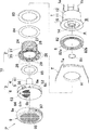
図1〜図4は、この発明の実施形態にかかる浴槽用温水口装置Pを示す図である。これらの図に示すように、この実施形態にかかる浴槽用温水口装置Pは、浴槽Tの側壁Taに設けられた取付孔Hに取り付けられるものであり、浴槽Tの外に設けられた給湯機(図示せず)からの温水を浴槽T内に供給して、湯はりなどの貯湯処理を行うことができる。 1-4 is a figure which shows the hot water port apparatus P for bathtubs concerning embodiment of this invention. As shown in these drawings, the hot water outlet device P for a bathtub according to this embodiment is attached to an attachment hole H provided in a side wall Ta of the bathtub T, and is a hot water heater provided outside the bathtub T. Hot water from (not shown) can be supplied into the bathtub T to perform hot water storage processing such as hot water.
さらに、浴槽T内の温水を吸い込んで給湯機に送り、それを再加熱し、その高温の温水を浴槽Tに戻して追い焚きなどの循環処理を行うこともできる。 Furthermore, the hot water in the bathtub T can be sucked and sent to the water heater, and it is reheated, and the hot water at the high temperature is returned to the bathtub T to perform circulation processing such as reheating.
なお、この浴槽用温水口装置Pは、この装置Pが備えている外管接続部1a,1bに対して、給湯機に繋がる往き管および戻り管のどちらを接続しても使用可能な、いわゆる無極タイプのものである。
In addition, this hot water port apparatus P for bathtubs can be used by connecting either the forward pipe or the return pipe connected to the water heater to the outer
図1〜図4に示すように、この実施形態の浴槽用温水口装置Pは、槽外取付具1と、装置本体10と、フィルタ部材9とを基本的な構成要素として備えており、さらに、装置本体10は、槽内取付具2と、流路形成部材3とを備えている。
As shown in FIG. 1 to FIG. 4, the hot water outlet apparatus P for a bathtub according to this embodiment includes an outside-
槽外取付具1は、一端側(前面側)が開放され、かつ他端側(後面側)が閉塞された円筒形状の外筒体12と、その外筒体12の内部に同軸上に配設された円筒形状の内筒体11を備えており、前記外筒体12の一端外周には、平板リング状の前部フランジ部15が一体形成される一方、外筒体12の他端閉塞壁には、軸方向へ沿って延びる第1および第2の外管接続部1a,1bが接続されている。また、前記外筒体12の一端側内周面には、雌ねじ部14が形成されている。
The tank
内筒体11の内側空間は、温水用の第1流路Aの一部として構成される一方、内筒体11と外筒体12との環状空間は、温水用の第2流路Bの一部として構成されている。また、前記第1の外管接続部1aが第1流路Aに連通される一方、第2の外管接続部1bが前記第2流路Bに連通されている。
The inner space of the
なお、前記内筒体11の一端側内周面には、合成ゴムなどからなるOリング81が収容配置されている。
Note that an O-
また、槽外取付具1の前部フランジ部15には、合成ゴムなどからリング状に成形され被覆パッキング8が外嵌されている。この被覆パッキング8の内周面に形成された環状の嵌合溝82aを前部フランジ部15の前方から嵌め込むことにより、被覆パッキング8は、該フランジ部15の外周面のほぼ全域を被覆した状態で密着固定される。
In addition, the
被覆パッキング8の前面側は、厚板状に形成されてパッキング本体82bとして構成されており、そのパッキング本体82bの表裏面には、周方向へ連続する複数の密着用凹凸部(図2)82cが一体形成されている。
The front surface side of the
装置本体10における槽内取付具2は、軸方向(前後方向)の両端が開放された円筒形状の筒体21と、この筒体21の一端外周に設けられた平板状の前部フランジ部25とを有し、これら筒体21と前部フランジ部25とは、ポリアセタート樹脂などの硬質樹脂により一体成形されている。
The in-
筒体21の外周面には、槽外取付具1の雌ねじ部14に螺合する雄ねじ部24が形成されており、この雄ねじ部24を雌ねじ部14に螺合することにより、槽内取付具2が槽外取付具1に結合される。
On the outer peripheral surface of the
前部フランジ部25の後側面と浴槽Tの側壁Taの内側面との間には、該槽内取付具2の筒体21に外嵌される平板リング状の弾性パッキング83が介在されている。この弾性パッキング83は、例えば合成ゴム等から成形されている。
Between the rear side surface of the
さらに、前部フランジ部25の後側面と弾性パッキング83との間には、槽内取付具2の筒体21に外嵌される平板リング状の緩衝部材84が介在されている。この緩衝部材84は、軟質性ないしは弾性を有するポリエチレン樹脂などの軟質合成樹脂で成形されている。
Further, between the rear side surface of the
まず、槽内取付け具2における筒体21に緩衝部材84、パッキング83を外嵌しておく。
First, the
そして、槽外取付具1の前部フランジ部15を前記浴槽Tの側壁Taの取付孔Hの周縁部に沿わせて配置した状態で、側壁Taの内側から槽内取付具2筒体21を前記取付孔Hを挿通するとともに、その外周面の雄ねじ部24を槽外取付具1における雌ねじ部14に螺入すれば、前記槽外取り付け具1におけるフランジ部15と槽内取付け具2における前部フランジ部25とが側壁Taを挟んだ状態で結合・固定される。
And in the state which has arrange | positioned the front
この組み付け状態では、緩衝部材84およびパッキング83が弾性変形し、パッキング83と前部フランジ部25との間のシール部の密着面が増大して水密性が確保される。
In this assembled state, the
また、前部フランジ部25の後側面に突条リブ(図示せず)を設けておけば、単位面積当たりの接触圧が高くなり、浴槽Tの側壁Taの内側面と前部ランジ部25との間の水密性が向上する。
Further, if a rib rib (not shown) is provided on the rear side surface of the
さらに、槽内取付け具2における雄ねじ部24を槽外取付具1における雌ねじ部14に螺合する際に前記突状リブの圧接によるパッキング83への応力が前記緩衝部材84により分散されて吸収されるから、パッキング83への応力集中が回避され、切り裂き(ねじ切れ)などが有効に防止される。
Further, when the male threaded
さて、装置本体10における流路形成部材3は、流路形成部材本体4と、蓋体6とを備えている。
The flow
流路形成部材本体4は、細長円筒形状の筒体41と、この筒体41の一端に連成された区画室部材5とを有しており、両者41,5は、硬質合成樹脂により一体成形されている。
The flow path forming member
筒体41は、槽外取付具1における内筒体11に対して密に内嵌されることにより、この内筒体11に連通して、前記第1の流路Aの一部を構成しており、また、この筒体41の外周面と前記槽内取付具2の筒体21の内周面との環状空間は、前記第2の流路Bの一部を構成している。
The
なお、筒体11の外周面と前記内筒体11の内周面との間は、前記Oリング81で水封されている。
A space between the outer peripheral surface of the
区画室部材5は、筒体41の一端に連成された円盤状の底板51と、その底板51の前面側外周を囲む外周壁52とが一体形成されており、この外周壁52の内側に前記槽内取付具2における前部フランジ部25が嵌まり込み、その前部フランジ部25の前面が底板51の後面に密に当接されている。
In the
区画室部材5における底板51の後面には、図5、図6および図14に示すように、前記外周壁52と同軸上に位置して槽内取付具2の筒体21の開口縁部に内嵌される環状壁部53が形成されている。
As shown in FIGS. 5, 6, and 14, the rear surface of the
この環状壁部53は、流路形成部材本体4における細長円筒形状の筒体41との周りに前記第2流路Bの連通する環状空間を成させるものである。
The
この環状壁部53の外周部位と前記筒体21の開口縁部との間には、環状パッキング85が介在されている。
An
上記底板51における環状壁部53に囲まれた部位には、図5、図6および図14に示すように、左右で2つに区画されており、左右方向の一方の側の上部および下部には、それぞれ第1吸込弁設置口54aと第1吐出弁設置口55aとが隔壁56aを挟んで形成されており、さらに、他方の側の上部および下部には、それぞれ第2吸込弁設置口54bと第2吐出弁設置口55bとが隔壁56bを挟んで形成されている。
As shown in FIGS. 5, 6, and 14, the portion surrounded by the
これら第1および第2吸込弁設置口54a,54bならびに第1および第2吐出弁設置口55a,55bは温水流通孔を兼務している。
The first and second suction
第1吸込弁設置口54aと第1吐出弁設置口55aとには、図4および図14に示すように、それぞれ第1吸込弁7aと第1吐出弁8aとがそれぞれ配備されており、また、第2吸込弁設置口54bと第2吐出弁設置口55bとには、それぞれ第2吸込弁7bと第1吐出弁8bとがそれぞれ配備されている。
As shown in FIG. 4 and FIG. 14, a
第1吸込弁7aと第1吐出弁8aとは一体形成されており、上下方向の中央部で前記隔壁56aを跨るように配置されている。
The
なお、第1吸込弁7aおよび第1吐出弁8aは、図4および図14に示すように、底板51の前面に対向する弁座71に対して、その後面側における一方のスリット71aを上下方向から挿入して設けられており、底板51から突出するピン72aに挿入・支持されている。
As shown in FIGS. 4 and 14, the
第1吸込弁7aは、温水の吸込時に、後方へ弾性変形して前記第1吸込弁設置口54aを開放する一方、第1吐出弁8aは、温水の吐出時に、前方へ弾性変形して前記第1吐出弁設置口55aを開放するように設定されている。
The
また、前記第2吸込弁7bと第1吐出弁8bも上記と同様に一体形成されており、上下方向の中央部で 前記隔壁56bに跨るように配置されている。
Further, the
なお、第2吸込弁7bおよび第2吐出弁8bも、図4および図14に示すように、底板51の前面に対向する弁座71に対して、その後面側における一方のスリット71bを上下方向から挿入して設けられており、底板51から突出するピン72bに挿入・支持されている。
As shown in FIGS. 4 and 14, the
第2吸込弁7bは、温水の吸込時に、後方へ弾性変形して前記第2吸込弁設置口54bを開放する一方、第2吐出弁8bは、温水の吐出時に前方へ弾性変形して前記第1吐出弁設置口55bを開放する。
The
なお、前記第1吸込弁7aおよび第1吐出弁8aならびに第2吸込弁7bおよび第2吐出弁8bには、それぞれ前記ピン72a,72bの圧入孔73a,73bが形成されており、弁座71にも、ピン圧入孔74a,74bが形成されている。
The
また、第1吸込弁7aおよび第2吸込弁7bの各前側には、図4、図13および図14に示すように、弁座71において、第1吸込弁7aおよび第2吸込弁7bが温水吐出時に前方へ変形するのを阻止する変形阻止リブ58,58がそれぞれ設けられており、また、第1吐出弁8aおよび第2吐出弁8bの後側には、図4、図13および図14に示すように、第1吐出弁8aおよび第2吐出弁8bが温水吸込時に後方へ変形するのを阻止する変形阻止リブ59,59がそれぞれ形成されている。
Further, as shown in FIGS. 4, 13, and 14, on the front side of the
また、前記第1吐出弁8aおよび第2吐出弁8bに前側には、温水吐出時に第1吐出弁8aおよび第2吐出弁8bが前方へ過剰変形するのを阻止する傾斜面付きリブ60(図13)が形成されている。
Further, on the front side of the
流路形成部材本体4における細長円筒形状の筒体41の前端開口は、前記第1吸込弁設置口54aと第1吐出弁設置口55aに対して非連通となるように左右方向の半分が閉塞される一方、第2吸込弁設置口54bと第2吐出弁設置口55bに対してのみ連通するように、左右方向の他方の半分のみが開放されて、第2吸込弁設置口54bと第2吐出弁設置口55bを一緒に取り囲む流路ガイド室57が形成されている(図5〜図7および図14参照)。すなわち、前記第1の流路Aは、前記第2吸込弁設置口54bと第2吐出弁設置口55bに連通している。
The front end opening of the elongated
蓋体6は、区画室部材5における外周壁52の前側開口に対応して硬質合成樹脂により円板形に成形されており、前記外周壁52の前側開口端面に接合されている。
The
この蓋体6の後面と、前記区画室部材5における底板51の前面とのいずれか一方、例えば蓋体6の後面には、図5、図6および図14に示すように、左右方向の一端から他端まで横断して、前記底板51の前面と蓋体6の後面との間の空間を上下で2分する横条隔壁リブ61と、この隔壁リブ61よりも上側の空間を左右で2分する縦条隔壁リブ62が形成されている。
One of the rear surface of the
横条隔壁リブ61は、前記第1吸込弁設置口54aと第1吐出弁設置口55aとの間ならびに第2吸込弁設置口54bと第2吐出弁設置口55bとの間をそれぞれ隔てる位置に対応している。
The
これにより、横条隔壁リブ61の上側空間は、前記第1吸込弁設置口54aおよび第2吸込弁設置口54bに連通して、吸込時の温水が通過する吸込流路として構成される一方、横条隔壁リブ61の下側空間は、第1吐出弁設置口55aおよび第2吐出弁設置口55bに連通して、吐出時の温水が通過する吐出流路として構成されている。
Thereby, the upper space of the
縦条隔壁リブ62は、前記第1吸込弁設置口54aおよび第1吐出弁設置口55aと第2吸込弁設置口54bおよび第2吐出弁設置口55bとの間を隔てる位置に対応している。
The
蓋体6の前面上部には、小孔からなる吸込口6a,6bの群が縦条隔壁リブ62を境界にして左右に分かれた状態で貫通形成されている。一方の吸込口6aは、第1吸込弁設置口54aに対応する一方、他方の吸込口6bは、前記第2吸込弁設置口54bに対応している。
In the upper part of the front surface of the
つまり、吸込口6aは、前記第2流路Bに対応し、吸込口6bは第1流路Aに対応している。
That is, the
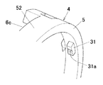
横条隔壁リブ61の下側空間に対応して区画室部材5の外周壁52の略下半部位が開放されており、この開放部位は、円弧状の吐出口6cとなっている。つまり、この吐出口6cは、前記第1吐出弁設置口55a、55bに対応しており、高温の温水を浴槽Tの側壁に沿って吐出するようになっている。
A substantially lower half portion of the outer
また、流通形成部材3における区画室部材5および蓋体6には、その外周面に、フィルタ部材9を取付けるための複数(例えば3個)の鉤状溝36・・・が円周方向へ等配した位置に形成されている。
Further, the
フィルタ部材9は、蓋体6の前面側から区画室部材5の外周面を覆うように配置されるもので、例えば合成樹脂により桶形に成形されており、その外周壁9aの内周面には、前記流路形成部材3の外周面における鉤状溝36・・・にそれぞれ対応して、複数(例えば3個)の係合突起96・・・が形成されている。
The
そして、これら係合突起96・・・を前記鉤状溝36・・・に挿入して回動変移するこにより、フィルタ部材9が前記流路形成部材3に着脱可能に装着される。
Then, by inserting these engaging
フィルタ部材9の前面壁には、前後方向へ貫通する多数の小孔からなる吸込用開口95が形成されており、また、その外周壁9aの下半部には、前記吐出口6cに対応して吐出開口97が形成されている。
The front wall of the
流路形成部材3における区画室部材5の外周壁52と槽内取付具2の前部フランジ部25の外周面とは、流路形成部材3を槽内取付具2に対して結合するための互いの結合部位として構成されている。
The outer
区画室部材5の外周壁52と槽内取付具2の前部フランジ部25とのいずれか一方、例えば区画室部材5の外周壁52の内周面には、図7および図8に示すように、径方向内方へ突出する結合用の複数(例えば3個)の係止突部31・・・が円周方向へ等配して形成されており、各係止突部31の突出方向(径方向内方)の先端面には、幅方向(円周方向)中央に節度用の小溝31aが形成されている。
As shown in FIG. 7 and FIG. 8 on one of the outer
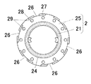
他方、つまり槽内取付具2の前部フランジ部25の前面外周縁部には、図9〜図11に示すように、流路係形成部材3の前方への押し込み操作に伴って、前記係止突部41・・・の進入を許容する複数の切欠開口26・・・が形成されている。
On the other hand, that is, on the front outer peripheral edge of the
また、槽内取付具2の前部フランジ部25の外周面には、区画室部材5の係止突部31を前方から切欠開口26に進入せた状態で該区画室部材5を軸周りの一方向(例えば左周り方向)へ回動操作した際に係脱可能に係合する係合溝部27が形成されており、切欠開口26とで、平面形状が鉤形溝となっている。
In addition, on the outer peripheral surface of the
前記切欠開口26および係合溝部27の数は、係止突部31・・と同じ3個であってもよいが、前記吐出口6cを下向きにさせる必要から流路形成部材3の円周方向(軸周り方向)の位置を決める際に、その位置が選択できるようにするために、係合突部31・・の数の整数倍、例えば2倍である6個が設けられている。勿論、さらに、増数することも可能である。
The number of the
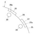
各係合溝部27の底面には、図9および図11に示すように、係止突部31の係合された際に前記小溝31aに嵌合して係合位置での節度を付与する小突条27aが形成されている。
As shown in FIGS. 9 and 11, the bottom surface of each engaging
ところで、この例では、図9〜図11に示すように、流路形成部材本体4を軸周りの一方向へ回動変移させた際に係止突部31に係合される係合溝部27のみならず、流路形成部材本体4を軸周りの他方向(例えば右周り方向)へ回動操作した際にも、係止突部31に係脱可能に係合する係合溝部28が形成されており、その係合溝部28の底面にも、係止突部31の小溝31aに嵌合して係合位置で節度を付与する小突条28aが形成されている。
By the way, in this example, as shown in FIGS. 9 to 11, when the flow path forming member
一方、蓋体6の前面には、図6にも示すように、区画室部材5まで貫通する一つのねじ挿通孔63が形成されており、このねじ挿通孔63には、流路形成部材3を槽内取付具2に対して回り止めするためのねじ64が挿通されるようになっている。
On the other hand, as shown in FIG. 6, one
また、記槽内取付具2の前部フランジ部25の前面には、ねじ64に螺合される複数のねじ孔29・・・が円周方向で等配して設けられている。このらのねじ孔29・・・は、流路形成部材3の円周方向の位置を決める際に、最適位置にできるだけ適合するものの一つが選択される。
In addition, a plurality of screw holes 29... Screwed into the
上記構成からなる温水口装置の浴槽Tへの取付け手順はとくに限定されるものではないが、例えば、以下のような手順で組み付けられる。 Although the attachment procedure to the bathtub T of the warm water mouth apparatus which consists of the said structure is not specifically limited, For example, it assembles | assembles in the following procedures.
まず、槽外取付具1の前部フランジ部15に被覆パッキング8を被せた状態で、この槽外取付具1を、浴槽Tの側壁Taの外側から取付孔Hに対応して配置する一方、槽内取付具2における前部フランジ部25の後面側に、筒体21に外嵌した緩衝部材84およびパッキング83を配置しておく。
First, in a state where the
その状態で、槽内取付具2の筒体21を浴槽Tの側壁Taの内側から取付孔Hに挿通し、筒体21の雄ねじ部24を槽外取付具1の雌ねじ部14に螺入すれば、前記槽外取付具1と槽内取付具2とが連通状態に結合されるともに、それぞれの前部フランジ部15,25により浴槽Tの側壁Taを挟持した状態で固定される。
In this state, the
ついで、流路形成部材3を槽内取付具2に取付ける。なお、流路形成部材3は、例えば工場出荷段階において、前記流路形成部材本体4と蓋体6との間に前記吸込弁7a,7bや吐出弁8a,8bがセットされた状態で蓋体6が流路形成部材本体4に溶着固定されている。
Next, the flow
この状態で、流路形成部材3における3個の係合突部31を前記槽内取付具2における3個の切欠開口26に進入させてから、流路形成部材3を回動操作して、該係止突部31を槽内取付具2における係合溝部27(もしくは係合溝部28)に係合する。
In this state, after the three engaging
この際、流路形成部材本体4における3個の係止突部31に対して槽内取付具2における切欠開口26および係合溝部27(28)が6個形成されているから、流路形成部材3の適正位置に適合する3個の切欠開口26および係合溝部27(28)を選択する。
At this time, six
具体的には、温水を吐出口6cから浴槽Tの側壁Taの内面に沿って下方へ吐出させるために、前記吐出口6cが下方に向く位置にとなるように流路形成部材本体4の回動位置を設定し、これに適合する3個の切欠開口26・・・を選択し、3個の係止突部31・・・を図12(a)に示すように、切欠開口26・・・に進入させる。
Specifically, in order to discharge hot water downward from the
この状態から流路形成部材3を回動操作して3個の係止突部31・・・を図12(b)に示すように、前記係合溝部27(28)に係合すればよい。
From this state, the flow
すなわち、流路形成部材3を後方へ押し付ける操作および回動操作を行えば、係止突部31および係合溝部27(28)を介して前記槽内取付具2に簡単に結合させることができ、従来のような複数個所をねじ止めするものに比して、結合作業性が向上する。
That is, if the operation and the rotation operation of pressing the flow
また、結合用のねじが不要となって、部品点数の削減が図れるうえ、前記槽内取付具2の前部フランジ部25の全周に多数のねじ受けボス部を設ける必要がなくなり、コンパクトに製作できる利点がある。
In addition, the number of parts can be reduced by eliminating the need for screws for connection, and it is not necessary to provide a large number of screw receiving bosses on the entire circumference of the
この流路形成部材3を上記とは反対方向へ回動した場合でも、係止突部31が係合溝部28(27)に係合する構成であるから、流路形成部材3の回動位置の選択範囲が広がり、所望位置に可及的に近づけて設定することが可能となる。
Even when the flow
この後、蓋体6および区画室部材5のねじ挿通孔63にねじ64を挿通するとともに、槽内取付具2におけるねじ孔29に螺入すれば、流路形成部材3の槽内取付具2に対する係合が意に反して解除されるのが防止される。勿論、ねじ64により止め手段に限らず、例えばピンを使う手段なども採用可能である。
After that, if the
最後に、流路形成部材3の前方からフィルタ部材9を被せ、該フィルタ部材9の係合突起96を前記区画室部材5の外周面の鉤状溝36に係合すれば、フィルタ部材9が区画室部材5に装着される。
Finally, when the
こうして浴槽Tに組み付けられた温水口装置Pにおいて、槽外取付具1の外管接続部1a,1bに、浴槽Tの外の給湯機からの配管が接続されて、浴槽システムが構成される。
In the hot water outlet device P assembled in the bathtub T in this way, piping from the hot water heater outside the bathtub T is connected to the outer
この浴槽システムにおいて、浴槽T内に温水を供給して貯湯する場合には、2つの外管接続部1a,1bの双方に温水をを供給して、第1および第2の流路A,Bを通って、流路形成部材3のに流入する。
In this bathtub system, when hot water is supplied and stored in the bathtub T, the hot water is supplied to both of the two outer
第1の流路A、つまり流路形成部材3における筒体41の内部空間を通って流入した温水の圧力によって吐出弁8bが前方へ変形される一方、第2の流路B、つまり流路形成部材3における筒体41と槽内取付具2における筒体21との間の環状空間を通って流入した温水の圧力によって吐出弁8aも前方へ変形される。
While the
これにより、左右の吐出弁設置口55a,55bがそれぞれ開放され、温水がこれら吐出弁設置口55a,55bを通過して区画室部材5の外周壁における吐出口6cおよびフィルタ部材9の吐出開口97から下方に向かって吐出される。この結果、浴槽Tの側壁Taに沿って温水が供給され、安全な状態で貯湯が行われる。
As a result, the left and right discharge
また、浴槽Tの温水を再加熱するような追い焚き処理を行う場合には、温水口装置Pにおける第1および第2の流路A,Bのうち、給湯機の往き管に接続された側の流路が吐出用流路として機能し、戻り管に接続された側の流路が吸込用流路として機能し、いわゆる温水の強制循環が行われる。 Moreover, when performing the reheating process which reheats the hot water of the bathtub T, the side connected to the outgoing pipe of the hot water heater among the 1st and 2nd flow paths A and B in the hot water outlet apparatus P This channel functions as a discharge channel, the channel connected to the return pipe functions as a suction channel, and so-called forced circulation of hot water is performed.
例えば、第1流路Aが吐出流路、第2流路Bが吸込流路となるように配管接続された場合、浴槽T内の温水の吸込時においては、給湯機の戻り管および第2流路Bの負圧によって、区画室部材5の底板51と蓋体6との空間が負圧になる。このため、浴槽T内の温水の水圧によって流路形成部材3における吸込弁7aが後方へ変形し、吸込弁設置口54aが開放される。これにより、浴槽T内の温水がフィルタ部材9の吸込用開口95を通して区画室部材5内に流入され、第2流路Bを通って給湯機に戻されて、再加熱される。
For example, when pipe connection is made such that the first flow path A is a discharge flow path and the second flow path B is a suction flow path, the return pipe of the hot water supply device and the second pipe are used when hot water in the bathtub T is sucked. Due to the negative pressure of the flow path B, the space between the
追い焚きされた温水の吐出時には、給湯機から供給された温水が第1流路Aを通って吐出弁8bを前方へ変形させる。これによって、吐出弁設置口8bが開放されて前記区画室部材5の外周壁における吐出口6cおよびフィルタ部材9の吐出用開口95から下方に向かって吐出されて、再加熱された温水が浴槽T内に安全な状態で戻されることになる。
When discharging the heated hot water, the hot water supplied from the water heater passes through the first flow path A and deforms the
ところで、この温水口装置Pの交換時や保守時に浴槽Tの側壁Taから取り外す場合には、前記フィルタ部材9を流路形成部材3から外した後、前記回り止め用のねじ64を外し、流路形成部材3を反対方向へ回動操作すれば、前記係止突部31と係合溝部27(28)との係合が解除されるから、前記流路形成部材3を前方に引けば、槽内取付具2との結合が解除される。そして、この槽内取付具2をねじ戻し操作して槽外取付具2と分離させることができる。
By the way, when removing from the side wall Ta of the bathtub T at the time of replacement or maintenance of the hot water outlet device P, the
なお、前記実施形態では、係止突部31を区画室部材5の外周壁52の内周面に設け、係合溝部27,28を槽内取付具2における前部フランジ部25に設けたものであるが、例えば区画室部材5の外周壁52に槽内取付具2における前部フランジ部25を外嵌させるような構成であれば、前記係止突部31を槽内取付具2における前部フランジ部25に設け、係合溝部27,28を区画室部材5の外周壁52側に設けるなど、各種変形構造の採用も可能である。
In addition, in the said embodiment, the latching
また、前記流路形成部材3における弁構造や流路構造などについても、流路形成部材3槽内取付具2との結合構造に支障を来さなければ、任意の構成を導入できるものである。
Further, regarding the valve structure, the flow path structure, and the like in the flow
1 槽外取付具
2 槽内取付具
3 流路形成部材
6a,6b 吸込口
6c 吐出口
7a,7b 吸込弁
8a,8b 吐出弁
9 フィルタ部材
10 装置本体
25 槽内取付具の前部フランジ部
26 切欠開口
27,28 係合溝部
31 係止突部
52 流路形成部材の外周壁部
64 回り止め手段
A 第1流路
B 第2流路
H 取付孔
P 浴槽用温水口装置
T 浴槽
Ta 浴槽の壁部
DESCRIPTION OF
Claims (4)
温水の浴槽内への吐出口と浴槽内の温水の吸込口とを有し、給湯機に配管接続された槽外取付具の2つの流路を前記吐出口および吸込口まで導く装置本体と、前記浴槽からの温水に対するフィルタ機能を有し、前記装置本体の所定個所に装着されたフィルタ部材とを備え、
前記装置本体は、前記浴槽の内側から前記壁部を貫通して前記槽外取付具に連通状態に結合された槽内取付具と、前記槽内取付具における結合用の前部フランジ部に対して結合される円形の流路形成部材とを備えており、
前記槽内取付具の前部フランジ部と流路形成部材の外周壁部とのいずれか一方には、円周方向へ等配された複数の係止突部が形成され、他方には、円周方向へ等配されて、槽内取付具の前部フランジに対する前方からの押し付け操作で係止突部を軸方向で相対進入させる切欠開口と、切欠開口に係止突部を進入させた状態から前記流路形成部材を軸周りへ回動操作した際の前記係止突部の変移に伴って、各係止突部にそれぞれ離脱可能に係合される複数の係合溝部とが形成されていることを特徴とする浴槽用温水口装置。 In the hot water outlet apparatus for a bathtub, which is attached to the bathtub wall in a penetrating state and supplies hot water supplied from a water heater installed outside the bathtub into the bathtub so as to be circulated.
An apparatus main body having a discharge port to the hot water bathtub and a hot water suction port in the bathtub, and leading two flow paths of the external fixture connected to the water heater to the discharge port and the suction port; It has a filter function for hot water from the bathtub, and comprises a filter member mounted at a predetermined location of the apparatus body,
The apparatus main body passes through the wall portion from the inside of the bathtub and is connected to the external fixture and connected to the external flange and the front flange portion for coupling in the internal fixture And a circular flow path forming member coupled to each other,
A plurality of locking projections equally distributed in the circumferential direction are formed on either the front flange portion of the in-tank fixture or the outer peripheral wall portion of the flow path forming member, and the other is a circular shape. A notch opening that is equally distributed in the circumferential direction and that makes the locking protrusion relatively approach in the axial direction by a pressing operation from the front against the front flange of the in-tank fixture, and a state in which the locking protrusion has entered the notch opening A plurality of engaging groove portions that are detachably engaged with the respective locking projections are formed along with the change of the locking projections when the flow path forming member is rotated around the axis. A hot water outlet device for a bathtub.
The hot-water port apparatus for bathtubs in any one of Claims 1-3 provided with the rotation prevention means of the flow-path formation member with respect to the front part flange part of the said in-tank fixture.
Priority Applications (1)
| Application Number | Priority Date | Filing Date | Title |
|---|---|---|---|
| JP2005194396A JP2007010281A (en) | 2005-07-01 | 2005-07-01 | Hot water port instrument for bathtub |
Applications Claiming Priority (1)
| Application Number | Priority Date | Filing Date | Title |
|---|---|---|---|
| JP2005194396A JP2007010281A (en) | 2005-07-01 | 2005-07-01 | Hot water port instrument for bathtub |
Publications (1)
| Publication Number | Publication Date |
|---|---|
| JP2007010281A true JP2007010281A (en) | 2007-01-18 |
Family
ID=37749022
Family Applications (1)
| Application Number | Title | Priority Date | Filing Date |
|---|---|---|---|
| JP2005194396A Pending JP2007010281A (en) | 2005-07-01 | 2005-07-01 | Hot water port instrument for bathtub |
Country Status (1)
| Country | Link |
|---|---|
| JP (1) | JP2007010281A (en) |
Cited By (1)
| Publication number | Priority date | Publication date | Assignee | Title |
|---|---|---|---|---|
| JP2009168408A (en) * | 2008-01-18 | 2009-07-30 | Onda Seisakusho Seki Kojo:Kk | Circulating implement for bathtub |
Citations (4)
| Publication number | Priority date | Publication date | Assignee | Title |
|---|---|---|---|---|
| JPH01153461A (en) * | 1987-11-03 | 1989-06-15 | Cebal | Tube for distributing paste having strip having integral type head section and double skirt section |
| JP2003156257A (en) * | 2001-11-20 | 2003-05-30 | Hatano Seisakusho:Kk | Forcible circulation bathtub connection device |
| JP2004116851A (en) * | 2002-09-25 | 2004-04-15 | Hashimoto Kinzoku Kogyo Kk | Circulation connector for bathtub |
| JP2005016794A (en) * | 2003-06-24 | 2005-01-20 | Onda Seisakusho:Kk | Bathtub circulation fitting |
-
2005
- 2005-07-01 JP JP2005194396A patent/JP2007010281A/en active Pending
Patent Citations (4)
| Publication number | Priority date | Publication date | Assignee | Title |
|---|---|---|---|---|
| JPH01153461A (en) * | 1987-11-03 | 1989-06-15 | Cebal | Tube for distributing paste having strip having integral type head section and double skirt section |
| JP2003156257A (en) * | 2001-11-20 | 2003-05-30 | Hatano Seisakusho:Kk | Forcible circulation bathtub connection device |
| JP2004116851A (en) * | 2002-09-25 | 2004-04-15 | Hashimoto Kinzoku Kogyo Kk | Circulation connector for bathtub |
| JP2005016794A (en) * | 2003-06-24 | 2005-01-20 | Onda Seisakusho:Kk | Bathtub circulation fitting |
Cited By (1)
| Publication number | Priority date | Publication date | Assignee | Title |
|---|---|---|---|---|
| JP2009168408A (en) * | 2008-01-18 | 2009-07-30 | Onda Seisakusho Seki Kojo:Kk | Circulating implement for bathtub |
Similar Documents
| Publication | Publication Date | Title |
|---|---|---|
| US10041233B2 (en) | Faucet valve housing assembly | |
| JP2012172772A (en) | Mixing faucet | |
| JP6080089B2 (en) | Hot and cold water mixing device | |
| JP2007010281A (en) | Hot water port instrument for bathtub | |
| JP2011069475A (en) | Automatic faucet | |
| JP4157093B2 (en) | Piping connector for bathtub and its construction method | |
| US20220163134A1 (en) | Mixer faucet | |
| JP7146251B2 (en) | Bathtub hot water supply adapter | |
| JP2008008579A (en) | Hot water supply opening adapter for bathtub | |
| JP4157075B2 (en) | Hot water outlet device for bathtub | |
| JP5222022B2 (en) | Bathtub adapter | |
| JP4157009B2 (en) | Hot water outlet device for bathtub | |
| JP4156971B2 (en) | Hot water outlet device for bathtub | |
| JP2009156508A (en) | Water suction port structure of circulation type bathtub | |
| JP5958879B2 (en) | Hot and cold water mixing device | |
| JP4469230B2 (en) | Connection structure of piping for embedded faucet | |
| JP4603212B2 (en) | Pipe connection mechanism of faucet | |
| JP4157100B2 (en) | Hot water outlet device for bathtub | |
| JP4308721B2 (en) | Hot water outlet device for bathtub | |
| JP2000193118A (en) | Faucet | |
| JP4819535B2 (en) | Bathtub adapter | |
| JP3962268B2 (en) | Water outlet | |
| KR101128391B1 (en) | Water Supply Valve Device | |
| KR200463659Y1 (en) | Open type cartridge having direct connection of hose | |
| JP5371622B2 (en) | Water purifier |
Legal Events
| Date | Code | Title | Description |
|---|---|---|---|
| A621 | Written request for application examination |
Free format text: JAPANESE INTERMEDIATE CODE: A621 Effective date: 20080528 |
|
| A977 | Report on retrieval |
Free format text: JAPANESE INTERMEDIATE CODE: A971007 Effective date: 20110107 |
|
| A131 | Notification of reasons for refusal |
Free format text: JAPANESE INTERMEDIATE CODE: A131 Effective date: 20110118 |
|
| A521 | Written amendment |
Free format text: JAPANESE INTERMEDIATE CODE: A523 Effective date: 20110318 |
|
| A131 | Notification of reasons for refusal |
Free format text: JAPANESE INTERMEDIATE CODE: A131 Effective date: 20110531 |
|
| A02 | Decision of refusal |
Free format text: JAPANESE INTERMEDIATE CODE: A02 Effective date: 20111108 |