JP2007008589A - Reclosable storing bag - Google Patents
Reclosable storing bag Download PDFInfo
- Publication number
- JP2007008589A JP2007008589A JP2006181648A JP2006181648A JP2007008589A JP 2007008589 A JP2007008589 A JP 2007008589A JP 2006181648 A JP2006181648 A JP 2006181648A JP 2006181648 A JP2006181648 A JP 2006181648A JP 2007008589 A JP2007008589 A JP 2007008589A
- Authority
- JP
- Japan
- Prior art keywords
- zipper
- bag
- flat valve
- opening
- joined
- Prior art date
- Legal status (The legal status is an assumption and is not a legal conclusion. Google has not performed a legal analysis and makes no representation as to the accuracy of the status listed.)
- Ceased
Links
Images


Classifications
-
- B—PERFORMING OPERATIONS; TRANSPORTING
- B65—CONVEYING; PACKING; STORING; HANDLING THIN OR FILAMENTARY MATERIAL
- B65D—CONTAINERS FOR STORAGE OR TRANSPORT OF ARTICLES OR MATERIALS, e.g. BAGS, BARRELS, BOTTLES, BOXES, CANS, CARTONS, CRATES, DRUMS, JARS, TANKS, HOPPERS, FORWARDING CONTAINERS; ACCESSORIES, CLOSURES, OR FITTINGS THEREFOR; PACKAGING ELEMENTS; PACKAGES
- B65D33/00—Details of, or accessories for, sacks or bags
- B65D33/16—End- or aperture-closing arrangements or devices
- B65D33/18—End- or aperture-closing arrangements or devices using adhesive applied to integral parts, e.g. to flaps
- B65D33/20—End- or aperture-closing arrangements or devices using adhesive applied to integral parts, e.g. to flaps using pressure-sensitive adhesive
-
- B—PERFORMING OPERATIONS; TRANSPORTING
- B65—CONVEYING; PACKING; STORING; HANDLING THIN OR FILAMENTARY MATERIAL
- B65D—CONTAINERS FOR STORAGE OR TRANSPORT OF ARTICLES OR MATERIALS, e.g. BAGS, BARRELS, BOTTLES, BOXES, CANS, CARTONS, CRATES, DRUMS, JARS, TANKS, HOPPERS, FORWARDING CONTAINERS; ACCESSORIES, CLOSURES, OR FITTINGS THEREFOR; PACKAGING ELEMENTS; PACKAGES
- B65D33/00—Details of, or accessories for, sacks or bags
- B65D33/16—End- or aperture-closing arrangements or devices
- B65D33/25—Riveting; Dovetailing; Screwing; using press buttons or slide fasteners
-
- B—PERFORMING OPERATIONS; TRANSPORTING
- B65—CONVEYING; PACKING; STORING; HANDLING THIN OR FILAMENTARY MATERIAL
- B65D—CONTAINERS FOR STORAGE OR TRANSPORT OF ARTICLES OR MATERIALS, e.g. BAGS, BARRELS, BOTTLES, BOXES, CANS, CARTONS, CRATES, DRUMS, JARS, TANKS, HOPPERS, FORWARDING CONTAINERS; ACCESSORIES, CLOSURES, OR FITTINGS THEREFOR; PACKAGING ELEMENTS; PACKAGES
- B65D31/00—Bags or like containers made of paper and having structural provision for thickness of contents
- B65D31/14—Valve bags, i.e. with valves for filling
-
- B—PERFORMING OPERATIONS; TRANSPORTING
- B65—CONVEYING; PACKING; STORING; HANDLING THIN OR FILAMENTARY MATERIAL
- B65D—CONTAINERS FOR STORAGE OR TRANSPORT OF ARTICLES OR MATERIALS, e.g. BAGS, BARRELS, BOTTLES, BOXES, CANS, CARTONS, CRATES, DRUMS, JARS, TANKS, HOPPERS, FORWARDING CONTAINERS; ACCESSORIES, CLOSURES, OR FITTINGS THEREFOR; PACKAGING ELEMENTS; PACKAGES
- B65D33/00—Details of, or accessories for, sacks or bags
- B65D33/16—End- or aperture-closing arrangements or devices
- B65D33/25—Riveting; Dovetailing; Screwing; using press buttons or slide fasteners
- B65D33/2508—Riveting; Dovetailing; Screwing; using press buttons or slide fasteners using slide fasteners with interlocking members having a substantially uniform section throughout the length of the fastener; Sliders therefor
- B65D33/2541—Riveting; Dovetailing; Screwing; using press buttons or slide fasteners using slide fasteners with interlocking members having a substantially uniform section throughout the length of the fastener; Sliders therefor characterised by the slide fastener, e.g. adapted to interlock with a sheet between the interlocking members having sections of particular shape
-
- B—PERFORMING OPERATIONS; TRANSPORTING
- B65—CONVEYING; PACKING; STORING; HANDLING THIN OR FILAMENTARY MATERIAL
- B65D—CONTAINERS FOR STORAGE OR TRANSPORT OF ARTICLES OR MATERIALS, e.g. BAGS, BARRELS, BOTTLES, BOXES, CANS, CARTONS, CRATES, DRUMS, JARS, TANKS, HOPPERS, FORWARDING CONTAINERS; ACCESSORIES, CLOSURES, OR FITTINGS THEREFOR; PACKAGING ELEMENTS; PACKAGES
- B65D33/00—Details of, or accessories for, sacks or bags
- B65D33/16—End- or aperture-closing arrangements or devices
- B65D33/25—Riveting; Dovetailing; Screwing; using press buttons or slide fasteners
- B65D33/2508—Riveting; Dovetailing; Screwing; using press buttons or slide fasteners using slide fasteners with interlocking members having a substantially uniform section throughout the length of the fastener; Sliders therefor
- B65D33/2566—Riveting; Dovetailing; Screwing; using press buttons or slide fasteners using slide fasteners with interlocking members having a substantially uniform section throughout the length of the fastener; Sliders therefor using two or more independently operable slide fasteners
-
- B—PERFORMING OPERATIONS; TRANSPORTING
- B65—CONVEYING; PACKING; STORING; HANDLING THIN OR FILAMENTARY MATERIAL
- B65D—CONTAINERS FOR STORAGE OR TRANSPORT OF ARTICLES OR MATERIALS, e.g. BAGS, BARRELS, BOTTLES, BOXES, CANS, CARTONS, CRATES, DRUMS, JARS, TANKS, HOPPERS, FORWARDING CONTAINERS; ACCESSORIES, CLOSURES, OR FITTINGS THEREFOR; PACKAGING ELEMENTS; PACKAGES
- B65D81/00—Containers, packaging elements, or packages, for contents presenting particular transport or storage problems, or adapted to be used for non-packaging purposes after removal of contents
- B65D81/18—Containers, packaging elements, or packages, for contents presenting particular transport or storage problems, or adapted to be used for non-packaging purposes after removal of contents providing specific environment for contents, e.g. temperature above or below ambient
- B65D81/20—Containers, packaging elements, or packages, for contents presenting particular transport or storage problems, or adapted to be used for non-packaging purposes after removal of contents providing specific environment for contents, e.g. temperature above or below ambient under vacuum or superatmospheric pressure, or in a special atmosphere, e.g. of inert gas
- B65D81/2007—Containers, packaging elements, or packages, for contents presenting particular transport or storage problems, or adapted to be used for non-packaging purposes after removal of contents providing specific environment for contents, e.g. temperature above or below ambient under vacuum or superatmospheric pressure, or in a special atmosphere, e.g. of inert gas under vacuum
- B65D81/2023—Containers, packaging elements, or packages, for contents presenting particular transport or storage problems, or adapted to be used for non-packaging purposes after removal of contents providing specific environment for contents, e.g. temperature above or below ambient under vacuum or superatmospheric pressure, or in a special atmosphere, e.g. of inert gas under vacuum in a flexible container
-
- B—PERFORMING OPERATIONS; TRANSPORTING
- B65—CONVEYING; PACKING; STORING; HANDLING THIN OR FILAMENTARY MATERIAL
- B65D—CONTAINERS FOR STORAGE OR TRANSPORT OF ARTICLES OR MATERIALS, e.g. BAGS, BARRELS, BOTTLES, BOXES, CANS, CARTONS, CRATES, DRUMS, JARS, TANKS, HOPPERS, FORWARDING CONTAINERS; ACCESSORIES, CLOSURES, OR FITTINGS THEREFOR; PACKAGING ELEMENTS; PACKAGES
- B65D81/00—Containers, packaging elements, or packages, for contents presenting particular transport or storage problems, or adapted to be used for non-packaging purposes after removal of contents
- B65D81/18—Containers, packaging elements, or packages, for contents presenting particular transport or storage problems, or adapted to be used for non-packaging purposes after removal of contents providing specific environment for contents, e.g. temperature above or below ambient
- B65D81/20—Containers, packaging elements, or packages, for contents presenting particular transport or storage problems, or adapted to be used for non-packaging purposes after removal of contents providing specific environment for contents, e.g. temperature above or below ambient under vacuum or superatmospheric pressure, or in a special atmosphere, e.g. of inert gas
- B65D81/2007—Containers, packaging elements, or packages, for contents presenting particular transport or storage problems, or adapted to be used for non-packaging purposes after removal of contents providing specific environment for contents, e.g. temperature above or below ambient under vacuum or superatmospheric pressure, or in a special atmosphere, e.g. of inert gas under vacuum
- B65D81/2038—Containers, packaging elements, or packages, for contents presenting particular transport or storage problems, or adapted to be used for non-packaging purposes after removal of contents providing specific environment for contents, e.g. temperature above or below ambient under vacuum or superatmospheric pressure, or in a special atmosphere, e.g. of inert gas under vacuum with means for establishing or improving vacuum
Abstract
Description
本発明は、一般的に排気手段を有する貯蔵用バッグに関する。特に、本発明はプラスチック製ジッパーによって再閉鎖可能な貯蔵用バッグに関する。 The present invention generally relates to a storage bag having exhaust means. In particular, the present invention relates to a storage bag that can be reclosed by a plastic zipper.
再閉鎖可能なプラスチック製ジッパーは熱可塑性の小袋やバッグを密封するのに有用である。典型的には、プラスチック製ジッパーは閉鎖具を形成する一対の相互に噛合可能なファスナー要素または輪郭部材を具えている。プラスチック製ジッパーのこの部材は、種々の形状をとることができ、例えば、いわゆる雄形輪郭部材と雌形輪郭部材とを有した相互に噛合するリブと溝部の要素、相互に噛合する交互のフック形状の閉鎖要素、相互に噛合するボール形状の閉鎖要素等が挙げられる。 Resealable plastic zippers are useful for sealing thermoplastic sachets and bags. Typically, a plastic zipper includes a pair of interlocking fastener elements or contour members that form a closure. This member of the plastic zipper can take various shapes, for example, interengaging rib and groove elements with so-called male and female contour members, alternating hooks interengaging with each other Examples thereof include a closure element having a shape and a ball-shaped closure element meshing with each other.
多くのパッケージ製品のために、パッケージを密封するための手段を提供することが望ましい。例えば、食品等の腐敗しやすい材料の入った未開封の再閉鎖可能なパッケージに破り易い密封を設けることが知られている。しかしながら、一旦この破り易い密封が破られてパッケージが開けられた場合、パッケージが再封鎖されても密封を元に戻すことはできない。 For many packaged products, it is desirable to provide a means for sealing the package. For example, it is known to provide a fragile seal on an unopened reclosable package containing perishable materials such as food. However, once the fragile seal is broken and the package is opened, the seal cannot be restored even if the package is resealed.
衣料等の製品を、再閉鎖可能なジッパーを有する排気された貯蔵バッグに収納することも知られている。詰められた後で排気される再閉鎖可能なバッグの場合、再閉鎖されたバッグが密封されることが望ましい。このような密封は、プラスチック製ジッパーによって行われることが必要である。この貯蔵用バッグは再使用可能なことが望ましいので、一回限りの破り易い密封では好ましくないことは明らかである。 It is also known to store products such as clothing in an evacuated storage bag having a reclosable zipper. In the case of a reclosable bag that is evacuated after being packed, it is desirable that the reclosed bag be sealed. Such sealing needs to be performed by a plastic zipper. Clearly, this storage bag is preferably reusable, so a one-time fragile seal is not preferred.
公知の排気可能な貯蔵用バッグは、バッグの内部を外気から密封する一次的な方法として作用するバッグの頭部空間の潰されたパッケージフィルムと共に、機械的閉鎖と二次的なシールを提供するジッパー輪郭部材に依拠している。このジッパー輪郭部材の問題点は、ジッパーの押潰し工程や、バッグの最終的なパッケージ化に際して、或いは、顧客によって使用される際に、半分に折畳まれたりしてそれが捩れた場合に、適当な気体のシールとして作用しないことにある。また、非常に幅の広いバッグでは、使用者がスライダーによってジッパーをうまく閉じなかった場合には、不均等な伸びによってジッパーが部分的に開いたままになることがある。捩れた後は、相互に連結されて押し付けられた部材同士は引き離され、外気から密封するその能力を喪失する。折畳まれた場合、バッグの頭部空間における比較的厚い(2.5ミル)フィルムであっても、バッグに空気が入ってくる漏洩通路が形成されてしまう。 Known evacuable storage bags provide a mechanical closure and secondary seal with a collapsed package film in the bag head space that acts as a primary method of sealing the interior of the bag from the outside air. Rely on the zipper profile. The problem with this zipper profile is that it can be folded in half and twisted during the zipper crushing process, final packaging of the bag, or when used by the customer. It does not act as a suitable gas seal. Also, in very wide bags, if the user does not close the zipper well with the slider, the zipper may remain partially open due to uneven stretching. After being twisted, the mutually connected and pressed members are pulled apart and lose their ability to seal from the outside air. When folded, even a relatively thick (2.5 mil) film in the head space of the bag will form a leak passage for air to enter the bag.
排気可能な貯蔵用バッグの真空密封を提供する解放可能なジッパーの構成の改良に対する要望が引き続いている。 There is a continuing need for improved releasable zipper configurations that provide a vacuum seal for evacuable storage bags.
本発明は、バッグの全幅を横切る扁平型の解放可能な手段によって密封可能な再閉鎖可能な真空貯蔵用バッグを対象としている。この扁平型の解放可能な手段は、外気がバッグの排気された内部空間に漏れて侵入するのを防ぐ障壁を提供するように構成されている。この貯蔵用バッグはプラスチック製のジッパーも具えている。扁平型の解放可能な手段は、ジッパーの製品側、ジッパーの使用者側、或いは、貯蔵用バッグに設けられた2つのジッパーの間に配置されることができる。 The present invention is directed to a reclosable vacuum storage bag that can be sealed by a flat, releasable means across the full width of the bag. The flat releasable means is configured to provide a barrier that prevents outside air from leaking into and entering the evacuated interior space of the bag. The storage bag also has a plastic zipper. The flat-type releasable means can be placed between the two zippers provided on the product side of the zipper, the user side of the zipper, or the storage bag.
本発明の一態様は、内部空間と開口部とを有する受容部であって、第1と第2の側部において接合され、かつ、底部において結合または連結された第1と第2の壁を具えて成る受容部と、前記第1と第2の壁によって前記開口部に、或いは、開口部の近傍にそれぞれ支持された第1と第2のジッパー部品であって、前記第1のジッパー部品は第1の閉鎖輪郭部材を具え、前記第2のジッパー部品は第2の閉鎖輪郭部材を具えており、前記第1と第2の閉鎖輪郭部材は相互に噛合可能となっているジッパー部品と、開放状態と閉鎖状態とを有し、前記受容部の内部空間が排気されたときの閉鎖状態にある間は閉じた状態を維持するように構成された扁平弁であって、該扁平弁は前記受容部の第1の側から第2の側まで延在し、閉鎖状態では前記扁平弁を通る空気遮断する扁平弁とを具備するバッグである。 One aspect of the present invention is a receiving portion having an internal space and an opening, the first and second walls being joined at the first and second sides and joined or connected at the bottom. A receiving portion comprising: a first zipper part; and a first zipper part supported on or near the opening by the first and second walls, respectively. Comprises a first closure contour member, the second zipper part comprises a second closure contour member, and the first and second closure contour members are engageable with each other; A flat valve having an open state and a closed state and configured to maintain a closed state while the internal space of the receiving portion is in a closed state when exhausted, Extends from the first side to the second side of the receptacle, and in the closed state the Tairaben a bag and a flat valve for air barrier through.
本発明の他の態様は、内部空間と開口部とを有する受容部であって、前記内部空間を形成する下方部分と前記開口部を形成する上方部分をそれぞれが有する第1と第2の壁を具えた受容部と、ジッパーの両端部に接合された噛合する第1と第2ののジッパー部品を具えたジッパーであって、両者の間にジッパー室を有し、前記第1のジッパー部品は帯状の第1の結合領域において前記第1の壁の前記上方部分に接合され、前記第2のジッパー部品は帯状の第2の結合領域において前記第2の壁の前記上方部分に接合されているジッパーと、前記第1と第2のジッパー部品の一方の一部分を被覆する粘着性材料で作られた塗膜であって、内面が露出し前記ジッパー室の全長に沿って延在している塗膜とを具えたバッグであって、前記ジッパーは、前記受容部の内部空間が排気されると前記ジッパー室が排気されるように配置された複数の孔を具え、前記ジッパーの部分は充分な可撓性を有し、前記ジッパー室が排気されると前記塗膜が対面する表面に接触するようになっているバッグである。 Another aspect of the present invention is a receiving portion having an internal space and an opening, wherein the first and second walls each have a lower portion forming the internal space and an upper portion forming the opening. A zipper comprising a receiving part comprising: a first zipper part and a second zipper part engaged with each other, and having a zipper chamber between the first zipper part and the zipper part Is joined to the upper part of the first wall in a strip-shaped first coupling region, and the second zipper part is joined to the upper part of the second wall in a strip-shaped second coupling region. And a coating made of an adhesive material that covers a portion of the zipper and one of the first and second zipper parts, the inner surface of which is exposed and extends along the entire length of the zipper chamber A bag comprising a coating film, wherein the zipper The zipper chamber has a plurality of holes arranged so that the zipper chamber is evacuated when the internal space of the receiving portion is evacuated, the zipper portion has sufficient flexibility, and the zipper chamber is evacuated. And a bag adapted to come into contact with the surface facing the coating film.
本発明の他の態様は、内部空間と開口部とを有する受容部であって、前記内部空間を形成する下方部分と前記開口部を形成する上方部分をそれぞれが有する第1と第2の壁を具えた受容部と、ジッパーの両端部に接合された相互に固定される第1と第2のジッパー部品を具えたジッパーであって、該第1のジッパー部品は第1のベース帯片と該第1のベース帯片の一方の側面から突出した第1と第2の閉鎖輪郭部材を具え、該第1と第2の閉鎖輪郭部材は互いに並行であり、前記第1のベース帯片は前記第1と第2の閉鎖輪郭部材の間に配置された複数の孔を具え、前記第2のジッパー部品は第2のベース帯片と該第2のベース帯片の一方の側面から突出した第3および第4閉鎖輪郭部材を具え、該第3および第4閉鎖輪郭部材は互いに平行であり、それぞれ前記第1と第2の閉鎖輪郭部材と噛合され、前記第1のベース帯片は帯状の第1の結合領域において前記第1の壁の前記上方部分に接合され、前記第2のベース帯片は帯状の第2の結合領域において前記第2の壁の前記上方部分に接合され、結合部の前記第1と第2のベース帯片は前記開口部が真っ直ぐな場合には前記噛合される閉鎖輪郭部材に略平行になっているジッパーと、前記受容部の開口部を気密に再密封するために前記第1と第2のベース帯片の間に配置された再密封可能な密封部であって、前記第1と第2のベース帯片の一方の閉鎖輪郭部材間に配置された内面の少なくとも一部を被覆するようにその長さに沿って延在する塗膜を具えている再密封可能な密封部とを具えたバッグである。 Another aspect of the present invention is a receiving portion having an internal space and an opening, wherein the first and second walls each have a lower portion forming the internal space and an upper portion forming the opening. A zipper comprising a receiving part comprising: a first zipper part and a first zipper part fixed to each other joined to both ends of the zipper, wherein the first zipper part comprises a first base strip; A first and second closing contour members projecting from one side of the first base strip, the first and second closing contour members being parallel to each other, wherein the first base strip is A plurality of holes disposed between the first and second closure profile members, the second zipper part projecting from a second base strip and one side of the second base strip; Third and fourth closing contour members, wherein the third and fourth closing contour members are parallel to each other Are engaged with the first and second closing contour members, respectively, and the first base strip is joined to the upper portion of the first wall in a strip-shaped first coupling region, A base strip is joined to the upper portion of the second wall in a strip-shaped second coupling region, and the first and second base strips of the coupling portion are engaged when the opening is straight. A resealable seal disposed between the first and second base strips to hermetically reseal the opening of the receptacle A coating that extends along the length of the inner surface of the first and second base strips so as to cover at least a portion of the inner surface thereof. A bag with a resealable seal.
本発明の更に他の態様は、内部空間と開口部を有する受容部であって、該受容部は第1と第2の側面に接合され、底部に結合、或いは、接続された第1と第2の壁を具えた受容部と、前記開口部を閉鎖するために噛合可能な第1と第2の閉鎖輪郭部材と、前記第1の側壁から第2の側壁まで延在して全長に沿って互いに接着、或いは、密着して、前記内部空間が排気されると内部空間の少なくとも大部分に外気が入り込むことを防止する密封する第1と第2の可撓性ウエブとを具えたバッグである。 According to still another aspect of the present invention, there is provided a receiving portion having an internal space and an opening, the receiving portion being joined to the first and second side surfaces and coupled to or connected to the bottom. A receiving portion having two walls, first and second closing contour members engageable to close the opening, and extending from the first side wall to the second side wall along the entire length A bag comprising a first and a second flexible web that are sealed or adhered to each other to prevent outside air from entering at least most of the internal space when the internal space is exhausted. is there.
本発明の他の態様は以下に開示されている。
異なる図において、類似する要素は同じ符号を付されているこれらの図面を参照して、以下の説明を行う。
Other aspects of the invention are disclosed below.
In the different figures, similar elements will be described in the following with reference to these figures, in which like reference numerals have been given.
図1は、排気可能な貯蔵用バッグ10の概略図であり、該バッグは、バッグ形成フィルムを折畳んで前後の壁の側部を熱融着し、開いた開口部18を有する受容部を形成ようにした前壁12と後壁(図1には示されていない)とを具えている。折畳む前に、弁集成体16が、バッグ形成フィルムのシートに形成された孔を通じて取付けられる。ジッパー組立体もこのフィルムに取付けられる。これは種々のやり方で行うことができる。例えば、一方のジッパー部品20をフィルムの一方の縁部分に取付け、次いでフィルムのウエブを折畳むようにできる。折畳まれた後に、フィルムの折り重ねられた部分が、ジッパー組立体の他方のジッパー部品22に取付けられる。或いは、折畳まれたウエブの対面する縁部分の間に閉じた状態のジッパー組立体を配置し、そしてジッパー部品の双方を一作業でウエブに融着するようにしてもよい。いずれの場合でも、ジッパーが取付けられた後に、バッグ形成フィルムの重畳する側部は熱融着されて、バッグの側部シーム線が形成される。ジッパー部品20、22の端部は押潰されて互いに融着され、結合端部を有するジッパーが形成される。この作業は側部シール作業とは別の作業で行ってもよい。
FIG. 1 is a schematic view of an
図2に示す実施形態では、弁集成体16の周囲と、該弁集成体に隣接、包囲するフィルムの孔の周縁部分との間が気密に密封されるように、弁集成体16は前壁12に取付けられる。任意の適宜な弁集成体を使用することができる。図2に示すように、ノズル26が、可撓性チューブ28によって負圧源30(例えば真空ポンプ)の排気ポートに接続される。排気の際に、バッグの内部は、直列に接続された弁集成体16の開いた弁体、ノズル26および可撓性チューブ28を介して、負圧源30に連通している。弁体が開かれると、負圧源30はバッグの内部から空気を吸引し、バッグ内に真空を形成する。図2は排気されたバッグの内部に貯蔵された物品24を示している。貯蔵される物品は衣料、本、或いは、空気や湿気に曝されない環境で最良に貯蔵されるその他の任意の物品とすることができる。排気は、使用者が衣料やブランケットを圧縮して、貯蔵する際にスペースを節約することも可能にする。
In the embodiment shown in FIG. 2, the
好適な弁集成体16の一例が図3に示されている。この弁集成体はベース部60を具備し、該ベース部は、貫通孔61と、該貫通孔の周縁に沿って設けられた接触面とを有する。前記弁集成体は、更に、第1の状態において前記貫通孔を開き、第2の状態において前記貫通孔を閉じるようにベース部に連結された弁体62を具えている。この弁体62は、ベース部60の一方の側面に設けられた弾性キャップ64、ベース部60の他方の側面に設けられたゲート66およびキャップ64をゲート66に連結するステム68を具えている。キャップ64は開口を有し、ステム68はキャップ64の開口に連通する空洞69と、該空洞およびステム68の外部に連通する少なくとも1つの開口70とを有する。ゲート66は、キャップ64が、変形していない第1の状態にある場合には、ベース部60の接触面に接してベースの貫通孔61を閉じ、キャップ64が、変形した第2の状態にある場合には、少なくとも部分的に前記接触面から離反して、ベース部60の貫通孔61を少なくとも部分的に開く。キャップ64が変形すると、キャップの開口は、ステムの空洞69と開口70を通じてベース部60の他方の側の空間に連通する。
An example of a
図3を更に参照すると、キャップ64は、ノズル26の先端部を弁集成体16のキャップに対して(矢印80で示される方向に)押し付けることによって変形され、これによってゲート66がベース部60から離反し、バッグの内部74と外部76の間での連通が可能になる。貯蔵用バッグから吸い出された気流は矢印72で示されている。ノズル26が弁集成体16のキャップから取外されると、キャップはその非変形形状(図3には示されていない)を回復する。キャップ64の弾性力によって、ゲート66はベース部60に対して上方に引張られ、再び気密に密封する。
Still referring to FIG. 3, the
バッグの壁は、ポリエチレンフィルムやナイロン/ポリエチレンの積層体のような可撓性を有する任意の通気性のない材料で作ることができる。弁集成体の構成部品は、従来の射出成形によって形成することができ、かつ、ポリエチレン、ポリ塩化ビニール、アクリロニトリル/ブタジエン/スチレン、その他の適宜な材料で形成可能である。 The wall of the bag can be made of any non-breathable material that has flexibility, such as polyethylene film or nylon / polyethylene laminate. The components of the valve assembly can be formed by conventional injection molding and can be formed of polyethylene, polyvinyl chloride, acrylonitrile / butadiene / styrene, or other suitable materials.
しかしながら、バッグの内部に真空を維持するために、再閉鎖可能なバッグのジッパーも密封しなければならない。本発明は、バッグが排気される時に、ジッパーを密封するための構造を目的にしている。 However, in order to maintain a vacuum inside the bag, the reclosable bag zipper must also be sealed. The present invention is directed to a structure for sealing a zipper when the bag is evacuated.
真空貯蔵用バッグに使用するのに適した密封されるジッパーの一実施形態が図4に示されている。このジッパーは一定の縮尺で図示されていない点に留意されたい。例えば、ベース帯片の厚さに対する幅の比率は、図面を測定することにより得られる比率より大きいくなっていよう。 One embodiment of a sealed zipper suitable for use in a vacuum storage bag is shown in FIG. Note that this zipper is not shown to scale. For example, the ratio of the width to the thickness of the base strip will be greater than the ratio obtained by measuring the drawing.
図4に示すように、この第1の実施形態にかかるパッケージは、前壁12と後壁14とを具えた受容部を具備している。壁12、14の上縁部分は受容部の開口部を形成している。図4には示されていないが、(図3に示されているようなタイプの)弁集成体が前壁12を貫通している。この弁集成体は、(上述したように)受容部の内部から空気を排出するように作動する。
As shown in FIG. 4, the package according to the first embodiment includes a receiving portion including a
押出成形されたプラスチック製のジッパーが開口部に装着される。このジッパーは、互いに噛合可能な一対のファスナー帯片またはジッパー半体部20、22を具備している。一般的に、ジッパー半体部の互いに噛合する輪郭部材は任意の形状とすることができる。例えば、ジッパーは互いに噛合するリブと溝部とを有する要素、或いは、交互に配設されたフック形状の閉鎖要素を具えることができる。図4に示す実施形態では、リブと溝部から成る閉鎖輪郭部材の一例が用いられている。リブは、溝部の開口部において対面するリップによって保持可能な任意の輪郭部材、例えば三角形、台形、半円形等の輪郭を形成する部材を有することができる。ジッパー部品20は、図4に示すように、ベース帯片32と、平行に離間配置された一対の雌型輪郭部材44、46とを具えている。一方、ジッパー部品22は、ベース帯片34と、雌型輪郭部材44、46に受容され噛合する一対の雄型輪郭部材40、42とを具えている。好ましいジッパー材料はポリエチレンである。しかしながら、ポリプロピレン等の他のプラスチック材料も使用可能である。図4には示されていないが、対面するジッパー部品の端部を例えば熱を加えて融合することによって、ジッパー部品20、22はジッパーの両端部で接合される。必要に応じて、ジッパーのベース帯片の端部はパッケージの外側(消費者側)に延長され、図4において破線で示すように、把持片50、52を提供するようにしてもよい。各把持片は、互いに平行に離間配置された複数のリブを具えて、消費者による把持片の端部の把持を容易にすることができる。そして、消費者は把持片50、52を把持してこれらを引き離し、ジッパーを開放する。
An extruded plastic zipper is attached to the opening. The zipper includes a pair of zipper strips or
ジッパー部品20、22は、例えば、ベース帯片の裏側に設けられたシーラント材料の層(図4には示されていない)によって、前壁12および後壁14の各上縁部分に接合される。これは、典型的には、ジッパー部品とシーラント層とを同時押出成形することによって達成される。バッグの前後壁のパネルは、それぞれ、熱融合または溶接(「熱融着」とも称される)によってジッパー半体部に取着される。或いは、互いに噛合可能なジッパー半体部は、接着または接合テープによって壁パネルに取付けることができ、また、ジッパーの輪郭部材はバッグ材料と共に押出成形してもよい。バッグの壁は、低密度ポリエチレン、実質的に線状のエチレン共重合体、C3〜C8アルファオレフィン、ポリプロピレン、塩化ポリビニリデン、これらのポリマーの2つ以上の混合物、或いは、これらのポリマーの1つと別のポリマーとの混合物などの種々のタイプの熱可塑性材料で形成される。当業者であれば、好適材料のこのリストは全てを網羅したものではないことは理解されるであろう。
The
図4に示すジッパーは、更にジッパーを密封するための手段を具えている。図4は2つの実施形態を示している。1つの実施形態では、密封手段は、雌型輪郭部材44、46の間の中心領域の塗膜としてベース帯片32に付与された感圧粘着層36を具えている(この実施形態では点線で示された層38は無視する)。感圧粘着剤は、軽い圧力が加えられると最大接合力を発揮する粘着剤である。この感圧性の塗膜は、ジッパー部品において、コロナ処理されて塗膜接着性を高めた部分に付与される。感圧粘着剤の塗膜は、ジッパー部品20の全長に沿って連続的に付与される。図4には示されていないが、閉鎖輪郭部材間の中心領域の全長に沿ってベース帯片32、34を押し付け合うことによって密封部が形成される。充分な圧力が付与されると、感圧粘着剤の塗膜36はベース帯片34の対面する中心領域に接着し(この密封された状態は図4には示されていない)、パッケージの開口部の全長に沿って密封部が形成される。後にジッパー部品20、22が引き離されると、感圧粘着剤の塗膜はベース帯片34から剥がされ、ベース帯片32に残る。別の例では、感圧粘着剤の塗膜は、ベース帯片32の代わりにベース帯片34に付与してもよい。密封部の機能はいずれの場合にも同じである。
The zipper shown in FIG. 4 further comprises means for sealing the zipper. FIG. 4 shows two embodiments. In one embodiment, the sealing means comprises a pressure sensitive
本発明の別の実施形態によれば、密封手段は雌型輪郭部材44、46の間の中心領域の塗膜として、ベース帯片32上に付与された結着性材料の層36と、雄型輪郭部材40、42の間の中心領域上の塗膜としてベース帯片34上に付与された結着性材料の層38(図4に点線で示されている)とを具えている。ここで結着性材料は、それ自体よりも他の材料に対して大きい結合強度で結合する粘着性の材料である。結着性塗膜は、ジッパー部品においてコロナ処理を受けて塗膜結着性を高めた部分に付与される。この結着性塗膜はジッパー部品20、22の全長に沿って連続して付与される。更に、閉鎖輪郭部材間の中心領域の全長に沿ってベース帯片32、34を押し付け合うことによって密封部が形成される。塗膜36は塗膜38に密着し(この結着状態は図4には示されていない)、パッケージの開口部の全長に沿う密封部が形成される。後にジッパー部品20、22が引き離されると、結着性塗膜は互いに剥がれる。
According to another embodiment of the present invention, the sealing means comprises a
本発明を実施するには、密封部の両側(即ち製品側と消費者側)に噛合するジッパー輪郭部材を設ける必要はない。例えば、密封部(図4の部材40、44)の消費者側の噛合するジッパー輪郭部材は、図5に示すように省略することができる。この場合、密封部はジッパー輪郭部材の消費者側に設けられる。図4で使用する参照番号と同じ符号の付されている他の要素は、前述と同じ機能を有している。
In order to carry out the present invention, it is not necessary to provide a zipper contour member that meshes with both sides of the sealing portion (that is, the product side and the consumer side). For example, the zipper contour member engaged on the consumer side of the sealing portion (
図面に示されていない更に他の実施形態によれば、密封部の製品側の噛合するジッパー輪郭部材(図4の部材40、44)は省略可能である。後者の場合、密封部はジッパー輪郭部材の消費者側に設けられる。
According to yet another embodiment not shown in the drawings, the zipper profile members (
図6は、図5の実施形態に類似してはいるが、異なったジッパー輪郭部材を有する1つの実施形態を示している。この実施形態は所謂「可変位置決め」ジッパーを採用している。この例では、一方のジッパー部品が3つの雄型輪郭部材42,42′、42″を具えており、他方のジッパー部品は、前記3つの雄型輪郭部材のうち2つを受け入れる2つの溝部を有する二重雌型輪郭部材を具えている。図6に示すように、雄型輪郭部材42、42′は各溝部に挿入可能となっており、該溝部は、反対方向を向いた戻り止めを具えた共通の中心脚部と、該中心脚部と協働する外側のグリッパー顎とによって形成されている。或いは、雄型輪郭部材42′、42″を二重雌型輪郭部材54の各溝部に挿入することによって、ジッパー輪郭部材を完全に噛合させることが可能である。
FIG. 6 shows one embodiment that is similar to the embodiment of FIG. 5, but has a different zipper profile. This embodiment employs a so-called “variable positioning” zipper. In this example, one zipper part has three
図6では(図5と同様に)、密封手段(塗膜36、38の一方または双方)がジッパー輪郭部材の消費者側のジッパーベース帯片32、34に付与されている。これとは対照的に、図7は、密封手段がジッパー輪郭部材の製品側に設けられている別の実施形態を示している。図7に示す実施形態は、図6に示すものと同じ可変位置決め式のジッパーを有している。
In FIG. 6 (similar to FIG. 5), sealing means (one or both of the
図5〜図7に示す各実施形態では、ジッパーのベース帯片の先端部分に離間したリブを設けることができ、これらの突出した先端部分、は図4を参照して説明したタイプの把持片として役立つ。 In each of the embodiments shown in FIGS. 5 to 7, a rib can be provided at the tip of the base strip of the zipper, and these protruding tips are gripping pieces of the type described with reference to FIG. 4. Useful as.
感圧粘着剤または結着性材料で作られた塗膜を有するジッパー部品は、外面にシーラント層を有するようにジッパー部品を同時押出成形し、このジッパー部品の内面にコロナ処理を行い、そして移動するジッパー部品のコロナ処理された面に所定幅の感圧粘着剤または結着性材料の層を付与する塗工機を通してジッパー部品を牽引することによって製造することができる。押出成形されたジッパー部品は、ベース帯片と、該ベース帯片の一方の側面から突出した閉鎖輪郭部材とを具えている。この塗膜は、閉鎖輪郭部材に隣接して平行に長手方向に延在する略平坦な表面に施される。コロナ処理によってジッパー部品に対する塗膜の接着性が高まり、シーラント層によってジッパー部品はバッグ製造フィルムに容易に接合することが可能となる。 A zipper part with a coating made of a pressure sensitive adhesive or binder material is co-extruded with a sealant layer on the outer surface, corona treated on the inner surface of the zipper part and moved It can be manufactured by pulling the zipper part through a coating machine that applies a layer of pressure sensitive adhesive or binding material to the corona treated surface of the zipper part. The extruded zipper part comprises a base strip and a closed contour member projecting from one side of the base strip. The coating is applied to a substantially flat surface extending longitudinally parallel to and adjacent to the closure profile member. Corona treatment increases the adhesion of the coating to the zipper part and the sealant layer allows the zipper part to be easily joined to the bag manufacturing film.
図8、9には、真空貯蔵用バッグに使用するのに適した密封されたジッパーの他の実施形態が示されている。図8に示すように、この実施形態にかかるバッグは、前壁12と後壁14とを具えた受容部を具備しており、これらの壁は側部で互いに接合され、かつ、底部において折曲部によって連結されている。これらの壁12、14の上縁部分は受容部の開口部を形成している。図8には示されていないが、弁集成体(例えば図3に示すタイプの)が前壁12を貫通している。この弁集成体は(上述したように)、貯蔵対象の物品がバッグの内側に収容され、開いていた開口部が閉じられた後に受容部の内部から空気を排出することができるように作動可能である。
8 and 9 show another embodiment of a sealed zipper suitable for use in a vacuum storage bag. As shown in FIG. 8, the bag according to this embodiment includes a receiving portion having a
図8を参照すると、押出成形されたプラスチック製の二重ジッパーがバッグの開口部に装着される。この二重ジッパーは、一対の噛合可能なファスナー帯片またはジッパー部品20、22を具え、各ジッパー部品は、前述のように一対の閉鎖輪郭部材を有している。リブと溝部から成る閉鎖輪郭部材が図8に示す実施形態に使用されている。
Referring to FIG. 8, an extruded plastic double zipper is attached to the opening of the bag. The double zipper includes a pair of matable fastener strips or
図8に示すように、ジッパー部品20は、ベース帯片32と、平行に離間配置された一対の雌型輪郭部材44、46を具えている。一方、ジッパー部品22は、ベース帯片34と、雌型輪郭部材44、46に受容され、これと噛合する一対の雄型輪郭部材40、42とを具えている。図8には示されていないが、ジッパー部品20、22は、例えば熱を付与してジッパー部品の対面する端部同士を融合することによって、ジッパーの両端部で接合される。貯蔵対称の物品がバッグ内部に収容された後に、図4に示すように、相補的な閉鎖輪郭部材の各対に圧力を加えて噛合させることによって、開いている開口部が閉じることができる。或いは、逆U字型のクリップ(図示せず)を二重ジッパー上に装着することができる。このようなクリップは、2004年8月3日に出願された米国特許出願第10/910724号「スライダーによって作動する解放可能な手段を有する排気可能な貯蔵用バッグ」に開示されている。このクリップは、いずれかの方向に移動したときに、流入する二重ジッパーの部分を押圧する。このクリップを二重ジッパーの一方の端部から他方の端部までスライドさせることによって、開口部は完全に閉鎖可能である。
As shown in FIG. 8, the
各ベース帯片の背面に設けられたシーラント材料(図4には示されていない)の層によって、ジッパー部品20は前壁12に接合され、ジッパー部品22は後壁14に接合される。或いは、各ジッパー部品は、シーラント層を用いることなく、バッグの壁に直接取付けるようにしてもよい。バッグの前後壁のパネルは、それぞれ前述のようにジッパー部品に熱融着される。
The
図8に示す例では、バッグの壁12の上部は、雌型輪郭部材44、46に平行に延びる一対の帯状の接合領域51、53でベース帯片32に接合される。一方、バッグバッグの壁14の上方部分は、雄型輪郭部材40、42に平行に延在する1つの帯状の接合領域55でベース帯片34に接合されている。或いは、噛合可能なジッパー部品は、接着帯片または結合帯片によって壁パネルに取付けることができる。図面には示されていないが、壁12、14の縁部分は共に熱融着されて側部シームを形成し、壁12、14の底部は折曲部で連結され(或いは共に接合され)、ジッパー片はジッパーの両端部で互いに接合されている。ジッパーのエンドシール部分は、閉鎖輪郭部材に垂直な矩形領域の形態をなし、ここでベース帯片は互いに融着され、そして閉鎖輪郭部材は熱と圧力の付与によって潰される。
In the example shown in FIG. 8, the upper portion of the
図8に示すジッパーは、更に、前述のように雌型輪郭部材44、46の間の中心領域における(好ましくは一定の厚さの)塗膜として、ベース帯片32に付与された低粘着性の粘着層36を具えている。粘着層36が設けられているベース帯片32の中心領域は、雌型輪郭部材44、46の間に延在し、(各ジッパーの両端部のジッパーのエンドシール、各ジッパーの閉鎖輪郭部材およびベース帯片32、34によって形成される)内部空間48が排気されると、内側に撓むように設計されていなければならない。雄型輪郭部材40、42間に延在する反対側のベース帯片34の中心領域もまた同様に、前記内部空間が排気されたときに内側に撓むように設計されていなければならない。図9には、空間48が排気されたときに、内側へ撓んだベース帯片32、34の中心部分が示されている。空間48が更に排気されると、ベース帯片32、34の内側に撓んだ部分は、ベース帯片32上の粘着剤塗膜36がジッパーの全長に沿って(即ち、ジッパーの一方の端部のシール部分から他方の端部のシール部分まで)、対面するベース帯片34の撓んだ中心領域の部分に接触し、これに接着して受容部の開口部が密封される。
The zipper shown in FIG. 8 is further provided with a low adhesive property applied to the
ここに開示されている種々の実施形態によれば、ジッパーの内部空間48は、受容部の内部空間58が排気されるのと同時に排気される。後者は前述の弁集成体を介して行われる。図8、9に示す実施形態によれば、空間48の排気は、ジッパーの内部空間48と受容部の内部空間58との間の直接的な連通を可能にする複数の排気孔(図8、9にはその1つのみが見られる)を設けることによって容易になる。図8、9に図示する実施形態は、各孔が円形である等間隔に並んだ一列の排気孔を有している。この列の最初と最後の排気孔は、各ジッパーのエンドシール部分の近傍にあることが望ましい。しかしながら、千鳥状に間隔を空けて配置された排気孔を具えた2列以上の配列を含めて他の配列の排気孔を用いてもよい。更に、排気孔は非円形形状(例えば楕円または正方形)を有していてもよい。バッグの排気の際に内部空間48からの空気の流出を促進するために、ウエブとジッパーとの結合領域55は、ベース帯片34の上部の近傍に設けられ、バッグの壁14のためのヒンジを提供する。このヒンジ構造もバッグが内部の力によって開かないようにする抵抗を増す。
According to various embodiments disclosed herein, the zipper
或いは、排気孔は、(ベース帯片34ではなく)雌型輪郭部材の脚部の双方に設けて、ジッパーの内部空間48と受容部の内部空間58とを連通させるようにしてもよい。更に、雄型輪郭部材に付加的な排気孔を必要に応じて設けることもできる。
Alternatively, the exhaust holes may be provided on both the legs of the female profile member (not the base strip 34) to allow communication between the
密封を破って二重ジッパーを開くために、ジッパーのベース帯片32、34の相互に対面する部分が、前述したように開かれて引き離される。そして、貯蔵用バッグの内容物が、開いた開口部を通じて取り出される。 In order to break the seal and open the double zipper, the mutually facing portions of the zipper base strips 32, 34 are opened and pulled apart as described above. Then, the contents of the storage bag are taken out through the opened opening.
二重ジッパーの全長に沿って、低粘着性の粘着剤の塗膜が連続的に付与される。この粘着剤は、排気されたバッグの外部の空気によって作用される圧力によって撓んだベース帯片34に付着するように構成されている。外気圧が作用すると、低粘着性粘着剤塗膜36は、(図9に示すように)対面するベース帯片34の中心領域に付着し、バッグの開口部の全長に沿って密封する。後にジッパー部品20、22が引き離されると、粘着剤塗膜はベース帯片34から剥がれて、ベース帯片32上に残る。別の例では、粘着剤塗膜はベース帯片32の代わりにベース帯片34に付与される。いずれの場合にも、密封の機能は同じである。しかしながら、この構成では、粘着層をベース帯片34に設けた後に排気孔を形成する必要がある。或いは、ベース帯片34を2本の帯状の結合領域でバッグの壁14に融着し、ベース帯片32を1本の帯状の結合領域でバッグの壁12に融着し、ベース帯片32上に排気孔を設けるようにできる。
A coating film of low-adhesive pressure-sensitive adhesive is continuously applied along the entire length of the double zipper. The pressure-sensitive adhesive is configured to adhere to the
図10、11に示す本発明の別の実施形態によれば、密封手段は、雌型輪郭部材44、46の間の中心領域に塗膜としてベース帯片32上に付与された結着性材料の層37と、雄型輪郭部材40、42の間の中心領域に塗膜としてベース帯片34上に付与された結着性材料の層38とを具えている。これらの結着性塗膜は、ジッパー部品22、22の全長に沿って連続的に付与されている。前述のように、ジッパーの内部空間48を排気することによって密封が得られる。塗膜37は塗膜38に密着し(この密着状態は図11に示されている)、バッグの開口部の全長に沿って密封する。後にジッパー部品20、22が引き離されると、結着性塗膜は互いに引き剥がされる。
According to another embodiment of the present invention shown in FIGS. 10 and 11, the sealing means is a binding material applied on the
低粘着性の粘着剤または結着性材料で作られた塗膜を有するジッパーは、外側にシーラント層を持つようにジッパー部品を同時押出成形し、ジッパー部品の内側にコロナ処理を行い、そして、移動するジッパー部品のコロナ処理された側に所定の幅の粘着剤または結着性材料の層を付与する塗工機を通して、ジッパー部品を牽引することによって製造することができる。押出成形されたジッパー部品は、ベース帯片と、該ベース帯片の一方の側面から突出し平行に離間する一対の閉鎖輪郭部材とを具えている。塗膜は閉鎖輪郭部材間に位置する略平坦な表面に付与され、閉鎖輪郭部材に平行に延在している。コロナ処理によって、ジッパー部品に対する塗膜の接着性が高まり、必要に応じてジッパー部品の反対側のシーラント層がこのジッパー層のバッグ形成フィルムに対する結着性を向上させる。 A zipper having a coating made of a low-tack adhesive or binder material, co-extrusion the zipper part with a sealant layer on the outside, corona treatment on the inside of the zipper part, and It can be manufactured by pulling the zipper part through a coating machine that applies a layer of adhesive or binding material of a predetermined width to the corona-treated side of the moving zipper part. The extruded zipper part comprises a base strip and a pair of closed contour members projecting from one side of the base strip and spaced apart in parallel. The coating is applied to a substantially flat surface located between the closed contour members and extends parallel to the closed contour members. Corona treatment increases the adhesion of the coating to the zipper part and, if necessary, the sealant layer on the opposite side of the zipper part improves the binding of this zipper layer to the bag-forming film.
本発明の別の実施形態にかかる排気可能な貯蔵用バッグのジッパー付き開口部が図12に示されており、図12において、図8、9に示す要素と機能的に均等な要素には同じ符号が付されている。図12に示すバッグも、上縁部分が受容部の開口部を形成している壁12、14を具えている。弁集成体(図12には示されていない)が前壁12を貫通している。押出成形されたプラスチック製の二重ジッパーがバッグの開口部に装着されている。この二重ジッパーは一対の噛合可能なファスナー帯片、或いは、ジッパー部品−20、22を具え、各ジッパー部品は前述のものに類似した一対の閉鎖輪郭部材を有している。ジッパー部品20は、ベース帯片32と、平行に離間する一対の雌型輪郭部材44、46を具え、ジッパー部品22は、ベース帯片34と、それぞれ雌型輪郭部材44、46に受容されてこれに噛合する一対の雄型輪郭部材40、42とを具えている。図12には示されていないが、ジッパー部品20、22はジッパーの両端部で接合されている。バッグの壁12の上部は、雌型輪郭部材44、46に平行に延びた一対の帯状の結合領域51、53でベース帯片32に接合され、バッグの壁14の上部は、雄型輪郭部材40、42に平行に延びた1つの帯状の結合領域55でベース帯片32に接合されている。壁12、14の縁部分は共に熱融着されて側部シームを形成し、その底部は折れ目で連結されている。
A zippered opening of an evacuable storage bag according to another embodiment of the present invention is shown in FIG. 12, in which the elements functionally equivalent to those shown in FIGS. The code | symbol is attached | subjected. The bag shown in FIG. 12 also includes
図12に図示する実施形態では、雌型輪郭部材46または雄型輪郭部材42(若しくは双方)の脚部の欠切部(図示せず)が排気孔として作用し、ベース帯片32、34の各々に移動可能に取付けられた一対の可撓性ウエブ82、84が密封手段として作用する。より詳細には、可撓性ウエブ82、84の各々は、二重ジッパーの長さに沿って延びている付着性フィルム(cling film)から成る矩形状帯片を具えている。この付着性フィルムは、典型的にはポリエチレンまたはポリ塩化ビニールで作られる。付着性フィルムは、それ自体と他の非接着性表面に貼り付く。図12に図示する構成では、ウエブ82の一方の縁部分が、雄型輪郭部材40の近傍において該雄型輪郭部材に平行な第1の帯状領域でベース帯片34に接合され、ウエブ82の反対側の縁部分が雄型輪郭部材42の近傍において該雄型輪郭部材に平行な第2の帯状領域でベース帯片34に接合されている。一方、ウェブ82において、前記第1と第2の帯状の接合領域の中間の付着していない部分は両者間で移動可能となっている。同様に、ウエブ84の一方の縁部分は雌型輪郭部材44の近傍において該雌型輪郭部材に平行な第3の帯状領域でベース帯片32に接合され、ウエブ84の反対側の縁部分は、雌型輪郭部材46の近傍において該雌型輪郭部材に平行な第4の帯状領域でベース帯片32に接合されている。一方、ウェブ84において、前記第3と第4の接合領域の中間の付着していない部分は両者間で移動可能となっている。ウエブ82、84の端部は、バッグの側部シーム(図示せず)に組み込まれている。製造工程において、ウエブ82、84は、二重ジッパーが閉じられる前に各ジッパーのベース帯片に接合されなければならない。バッグのフィルムは、ウエブ82、84がベース帯片に接合される前後でベース帯片に接合することができる。
In the embodiment shown in FIG. 12, the notch (not shown) of the leg of the
図12において部分的に示されているバッグの内部空間が、前記弁集成体(図示せず)を経て排気されると、雌型輪郭部材46の欠切部を介してバッグの内部空間と連通している、ウエブ82、84および二重ジッパーによって形成される内部空間48′も排気される。外気圧によって、内部空間48′の両側のウエブ82、84の部分が互いに接触し、それによって二重ジッパーの全長に沿って密封される。この密封が貯蔵の際にバッグの内部の真空の維持を補助する。
When the interior space of the bag partially shown in FIG. 12 is exhausted through the valve assembly (not shown), it communicates with the interior space of the bag via the cutout portion of the
或いは、各ウエブ82、84を非付着性材料で形成し、ウエブの対面する表面に結着性材料を塗布してもよい。
Alternatively, each of the
図12に図示する実施形態の一変形によれば、付着性フィルムから成る一枚のウエブのみを使用することができる。このウエブと該ウェブに対面するベース帯片の間の内部空間が排気されると、前記ウェブおよびベース帯片が互いに接触して、付着性フィルムが対面するベース帯片に付着するようになっている。前述したように、対面するベース帯片は、内部空間が排気されるにつれて内側に撓んで単独の付着性フィルムに接触するようにできる。或いは、前記単独のウエブは非粘着性材料で形成することができ、バッグが排気された場合に対面するベース帯片に接着する低粘着性の粘着剤を該ウェブに塗布することができる。 According to a variant of the embodiment illustrated in FIG. 12, only one web of adhesive film can be used. When the internal space between the web and the base strip facing the web is evacuated, the web and the base strip come into contact with each other, and the adhesive film adheres to the facing base strip. Yes. As described above, the facing base strip can bend inward as the interior space is evacuated to contact a single adhesive film. Alternatively, the single web can be formed of a non-tacky material, and a low tack adhesive can be applied to the web that adheres to the base strip facing when the bag is evacuated.
本発明の更に他の実施形態にかかる排気可能な貯蔵用バッグのジッパー付き開口部が、図13に示されている。図13において、図12に示す要素と機能的に均等な要素には同じ符号が付されている。図13に部分的に示すバッグも、上縁部分が受容部の開口部を形成している壁12、14を具えている。弁集成体(図13には示されていない)が前壁12を貫通している。ベース帯片を有する二重ジッパーの代わりに、互いに平行な一対のジッパーがバッグの開口部に設けられている。各ジッパーはジッパー部品86、88および90、92の各対を具えている。ジッパー部品86はベース部94から突出した雄型輪郭部材40を具え、ジッパー部品88はベース部96から突出した雌型輪郭部材44を具えている。ジッパーが閉じられると、雄型輪郭部材40は雌型輪郭部材44に係合する。ジッパー部品90は、ベース部98から突出した雄型輪郭部材42を具え、ジッパー部品92はベース部100から突出した雌型輪郭部材46を具えている。ジッパーが閉じられると、雄型輪郭部材42は雌型輪郭部材46に係合する。この実施形態では、可撓性ウエブ82の両縁部分が各ベース部94、98の背面に接合され、可撓性ウエブ84の両縁部分がベース部96、100の背面に接合される。ウエブ82、84の中間部分はジッパー間の内部空間に掛け渡されている。軟化または溶融され次いで冷却されるシーラント材料で形成されたビード部分104、108によって、バッグの壁12は可撓性ウエブ84の縁部分に融着される。バッグの壁14も同様に、軟化または溶融され次いで冷却されるシーラント材料で形成されたビード部分102、106によって可撓性ウエブ82の縁部分に融着される。これらのビード部分は、バッグの壁を可撓性ウエブ82、84に融着する際にウエブの焼損を防止する。本実施形態でも各ジッパーの端部は接合される。バッグの壁および可撓性ウエブ82、84も、ジッパー間の領域においてバッグの側部に接合される。本実施形態でも、受容部の内部空間58と、可撓性ウエブ82、84およびジッパーによって形成された内部空間48との間を連通させる欠切部が、雌型輪郭部材46(または雄型輪郭部材42若しくは双方)に設けられている。更に、前後壁12、14において可撓性ウエブ82、84の移動可能な中間部分に対面する部分に複数の孔57が設けられている。弁集成体を介して受容部の内部空間58が排気されると、ウエブ82、84の間の内部空間48が排気され、可撓性ウエブ82と壁14の間、および可撓性ウエブ84と壁12の間の空間に大気圧の空気が流入する。これによって、可撓性ウエブ82、84が、内部空間の全長に沿って互いに接触して付着し合い、密封される。
A zippered opening of an evacuable storage bag according to yet another embodiment of the present invention is shown in FIG. 13, elements that are functionally equivalent to the elements shown in FIG. 12 are denoted by the same reference numerals. The bag partially shown in FIG. 13 also comprises
本発明の更に他の実施形態にかかる排気可能な貯蔵用バッグのジッパー付き開口部が図14に示されている。図14において、図13に示す要素と機能的に均等な要素には同じ符号が付されている。図14に部分的に示されているバッグも、上縁部分が受容部の開口部を形成する壁12、14を具えている。弁集成体(図14には示されていない)が前壁12を貫通している。一対の互いに平行なジッパーがバッグの開口部に設けられている。各ジッパーは、ジッパー部品86、88および90、92の各対を具えている。この実施形態では、後壁14の互いに平行な帯状部分が各ベース部94、98の背面に接合され、前壁12の互いに平行な帯状部分が各ベース部96、100の背面に接合され、壁12、14の中間部分はジッパー間の内部空間に掛け渡されている。本実施形態でも、各ジッパーのジッパー部品の端部は接合されている。バッグの壁12、14は、バッグの側部において、ジッパー間の領域(および受容部のジッパー付き開口部の上下)で接合され、ジッパーの端部が互いに接合されている領域でジッパーに接合されている。図14に部分的に示す貯蔵用バッグは、更に、雄型輪郭部材86、90の間の領域における(好ましくは一定の厚さを有する)塗膜として後壁14に付与された低粘着性粘着層36を具えている(或いは、低粘着性の粘着剤は前壁12に付与されてもよい)。バッグの壁の材料は充分な可撓性を有し、(ジッパーの両端部におけるジッパーのエンドシール部、各ジッパーの閉鎖輪郭部材、およびバッグの壁の対面する部分によって形成される)内部空間48が排気されると、粘着層36が付与されている後壁14の領域およびこれに対面する前壁12の領域が内側に撓む。バッグの外側の高い圧力が両方の可撓性の壁部分を共に押し付ける。内部空間48の両側のバッグの壁が内側に撓むと、一方の壁の粘着剤塗膜36は、ジッパーの全長に沿って(即ち、一方のジッパー端部から他方のジッパー端部まで)他方の壁の対面部分に密着し、受容部の開口部を密封する。
A zippered opening of an evacuable storage bag according to yet another embodiment of the present invention is shown in FIG. In FIG. 14, elements that are functionally equivalent to the elements shown in FIG. The bag partially shown in FIG. 14 also comprises
図15に図示する他の実施形態によれば、結着性材料の層37、38が、前後壁14、12においてジッパーの間の部分に付与されている。本実施形態でも、バッグの壁の材料は充分な可撓性を有し、内部空間48が排気されると、結着層37が付与された後壁14の領域、および、結着層38が付与された前壁12のこれに対面する領域の各々が内側に撓む。バッグ外部の高い圧力がこれらの可撓性壁部分を押し付ける。内部空間48の両側のバッグの壁の内側に撓んだ部分が互いに接触すると、一方の壁の結着性塗膜は、ジッパーの全長に沿って(即ち一方のジッパー端部から他方のジッパー端部まで)他方の壁の対面する結着性塗膜に密着し、受容部の開口部を密封する。
According to another embodiment illustrated in FIG. 15, layers 37, 38 of binding material are applied to the front and
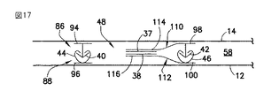
図16には、本発明の他の実施形態にかかる排気可能な貯蔵用バッグのジッパー付き開口部が示されている。図16において、図14に示す要素と機能的に均等な要素には同じ符号が付されている。この実施形態では、第2のジッパーが一対のジッパー部品110、112により置換されている。この一対のジッパー部品は延長フランジ114、116を有しており、該延長フランジが、内部空間48の中に延在している密封部を形成する。ジッパー部品110はベース部98から突出した雄型輪郭部材42を具え、ジッパー部品92はベース部100から突出した雌型輪郭部材46を具えている。延長フランジ114の一方の側縁はベース部98の一方の側縁に接続され、延長フランジ116の一方の側縁はベース部100の一方の側縁に接続されている。好ましくは、延長フランジ116の厚さはベース部の厚さより薄いか、或いは、これに等しい。延長フランジ114、116の一方は、他方の延長フランジに対面する面に低粘着性材料の塗膜36を有する。延長フランジの端部は受容部の側部シーム(図16には示されていない)に捕捉されて拘束されている。受容部の内部空間58が排気されると、内部空間48の空気は雄型および雌型輪郭部材42、46の間から、排気されている前記内部空間に流出し、内部空間48が排気される。バッグ外部の大気圧によって、内部空間48を形成するバッグの壁部分が押圧され、延長フランジ114、116を互いに押し付ける。粘着剤塗膜36が対面する延長フランジに接触してこれに接着すると、受容部の開口部は密封される。図16は、開口部が密封された後に、ジッパー部品86、88を通じて漏れた外気が、内部空間48を形成するバッグの壁部分を押し離す状態を示している。
FIG. 16 shows a zippered opening of an evacuable storage bag according to another embodiment of the present invention. 16, elements that are functionally equivalent to the elements shown in FIG. 14 are denoted by the same reference numerals. In this embodiment, the second zipper is replaced by a pair of
図17に図示する実施形態は図16に示す実施形態とは異なり、一方の延長フランジのみに粘着剤の塗膜を付与することに代えて、各延長フランジ114、116が結着性材料で塗布されている。バッグを排気する際に外気によって延長フランジが押圧されると、結着性塗膜が接触して互いに密着し、受容部の開口部を密封する。
The embodiment shown in FIG. 17 differs from the embodiment shown in FIG. 16 in that each of the
図18に図示する他の実施形態によれば、延長フランジは付着性フィルムで作られている。図18に部分的に示されているバッグも、上縁部分が受容部の開口部を形成している壁12、14を具えている。弁集成体(図18には示されていない)が前壁12を貫通している。互いに平行な一対のジッパーもバッグの開口部に設けられている。各ジッパーはジッパー部品86、88および90、92の各対を具えている。ジッパー部品86は、ベース部94から突出した雄型輪郭部材40を具え、ジッパー部品88は、ベース部96から突出した雄型輪郭部材44を具えている。ジッパー部品90はベース部98から突出した雄型輪郭部材42を具え、ジッパー部品92はベース部100から突出した雌型輪郭部材46を具えている。この実施形態では、帯状の可撓性ウエブ82の上縁部分はベース部98の背面に接合され、対面する帯状の可撓性ウエブ84の上縁部分はベース部100の背面に接合される。ウエブ82、84の端部はバッグの側部シームに組み込まれ、ウエブ82、84の中間部分はジッパー間の内部空間の一部に掛け渡されている。軟化または溶融され次いで冷却されるシーラント材料により形成されたビード部分108によって、バッグの壁12は可撓性ウエブ84の上縁部分に融着される。同様に、軟化または溶融され次いで冷却されるシーラント材料により形成されたビード部分106によって、バッグの壁14は可撓性ウエブ82の上縁部分に融着される。本実施形態でも、各ジッパーのジッパー部品の端部は接合される。受容部の内部空間58が弁集成体を通じて排気されると、可撓性ウエブ82、84は内部空間の全長に沿って互いに接触して付着し、密封する。
According to another embodiment illustrated in FIG. 18, the extension flange is made of an adhesive film. The bag partially shown in FIG. 18 also comprises
図13〜図18に示す実施形態では、排気孔、即ちジッパー間の空間48の排気を促進するための孔として作用する欠切部(図示せず)を雌型輪郭部材46または雄型輪郭部材42(或いは両者)の脚部に設けてもよい。
In the embodiment shown in FIGS. 13 to 18, the
図19、20には更に他の実施形態が示されている。この実施形態よれば、受容部の開口部を密封するために帯状の一対の可撓性ウエブ82、84が設けられている。これらのウエブ82、84は、(前述のようにジッパー部品90、92を具えた)ジッパーと、貯蔵される物品を入れる受容部の内部空間58の一部との間に設けられている。各可撓性ウエブ82、84は、バッグの全幅にわたって延在する付着性フィルムの矩形状帯片を具えている。図19に示す構成では、ウエブ82の各縁部分は、平行に離間した帯状領域118、120において後壁14に接合され、ウエブ84のこれに対面する縁部分は、平行に離間した帯状領域122、124において前壁12に接合されている。ウエブ82、84の端部は貯蔵用バッグの側部シームに組み込まれている。ウエブ82、84の非取付け部分は、周囲の取り付けられた外周部分から移動可能となっている。更に、ウエブ84との結合領域122、124の間の前壁12の部分、および、ウエブ82との結合領域118、120の間の後壁14の部分には、孔57が形成されている。図20に示す構成では、間隔を置いて一列に配置された孔57が後壁14に設けられて、(後壁14とウエブ82とによって形成される)内部空間126と外気との間の連通を可能にする。また、間隔を置いて一列に配置された他の孔57′が前壁12に設けられており、(前壁12とウエブ84とによって形成される)内部空間128と外気との間の連通を可能にしている。
19 and 20 show still another embodiment. According to this embodiment, a pair of belt-like
図19、20に示すバッグは、次のように使用できる。先ず、ユーザーがジッパーを開き、貯蔵対象の物品を受容部の内部空間58に挿入し、次にジッパーを閉じる。そして、弁集成体16が負圧源に接続される。次に、内部空間58が排気される。最初、付着性フィルムのウエブ82、84は離れているが、内部空間58の内圧が減少するにつれて、外気圧によって、孔57、57′を通じて空気が内部空間126、128に流入する。ウエブ82、84を横切る圧力差によって、該ウェブは互いに押圧され、受容部の全幅に沿って接触する。ウエブ82、84の接触部分は付着し、受容部の開口部が密封される。この密封は、貯蔵の際にバッグの内側の真空を維持することを助ける。
The bag shown in FIGS. 19 and 20 can be used as follows. First, the user opens the zipper, inserts the item to be stored into the
或いは、ウエブ82、84は非粘着性材料で作られた可撓性ウエブに置き換えられ、ウエブの対面する表面は結着性材料で塗布され、或いは、ウエブの対面する表面の一方は低粘着性の粘着剤で塗布されている。例えば、これらの可撓性ウエブは、粘着性付与剤で塗布された線状低密度ポリエチレン(LDDP)の延伸包装フィルムを具えることができる。或いは、押出成形前に粘着性付与剤をLDDP樹脂にブレンドして、押出成形後に粘着性付与剤がフィルムの表面に移動するようにしてもよい。
Alternatively, the
本発明の更に他の態様によれば、可撓性ウエブ82、84はコーキング材、或いは、液体として作用する半液対状表面を有する材料で形成するようにしてもよい。これは自己シール、或いは、流動してエアロックを形成し、低い浸透性を有する。また、この材料は、折曲げられた場合に剥がれたり割れたりしてはならず、そして所望の最少期間を通じて完全に乾燥してはならない。更に、布が表面に付着してはならない。特定の用途のために、可塑剤入りのビニールや未加硫ラテックスを用いることができよう。
According to yet another aspect of the present invention, the
上述のように、バッグの材料、ジッパーのベース帯片、またはこれらのバッグの材料やジッパーのベース帯片に移動可能に取付けられた可撓性ウエブは、粘着性付与剤等のシーラント材料によって処理することができよう。これらの場合、シーラントは気体遮断材として作用するのみでなく、ベース帯片同士を半機械的に保持する粘着作用も奏する。 As described above, bag materials, zipper base strips, or flexible webs movably attached to these bag materials or zipper base strips are treated with a sealant material such as a tackifier. I can do it. In these cases, the sealant not only acts as a gas barrier, but also exhibits an adhesive action that holds the base strips semi-mechanically.
開示された各実施形態では、ジッパー、シーラントのビード部分、付着性フィルム、接着性塗膜、結着性塗膜は、貯蔵用バッグの全幅のわたって延在している。同様に、これらの構成部材のいずれかが互いに接合され、或いは、バッグの壁に接合されている領域は、バッグの全幅にわたって延在している。 In each disclosed embodiment, the zipper, the bead portion of the sealant, the adhesive film, the adhesive coating, and the binding coating extend across the entire width of the storage bag. Similarly, the region where any of these components are joined together or joined to the bag wall extends across the entire width of the bag.
扁平型の解放可能な手段を平行な2つのジッパーの間に配設する場合には、該扁平型の開放可能な手段は、前述の米国特許出願第10/910724号に開示されたように、スライダーの操作によって密封することができよう。これは、貯蔵用バッグの内部空間が排気される前に行うことができる。米国特許出願第10/910724号の開示は、本明細書と一体をなすものとして参照する。 When the flat-type releasable means is disposed between two parallel zippers, the flat-type releasable means, as disclosed in the aforementioned US patent application Ser. No. 10/910724, It can be sealed by operating the slider. This can be done before the interior space of the storage bag is evacuated. The disclosure of US patent application Ser. No. 10 / 910,724 is hereby incorporated by reference.
排気される貯蔵用バッグ(或いはそれの閉鎖具)を密封する扁平弁を設ける利点は色々ある。この扁平弁は外気がバッグの排気された内部空間に漏れて入ることを防ぐ障壁を提供する。扁平弁は、バッグが折畳まれた場合、特に各膜が1/2ミルの厚さを有する粘着性の延伸フィルムと同じ位の薄ければ、チャンネルの漏れや損傷に対して影響を受けることが少ない。また、薄くて広い扁平弁は、使用中の皺によって生じるチャンネル漏れのための曲がりくねった通路を形成する。 There are various advantages to providing a flat valve that seals the evacuated storage bag (or its closure). This flat valve provides a barrier that prevents outside air from leaking into the evacuated interior space of the bag. Flat valves are susceptible to channel leakage and damage when the bag is folded, especially if each membrane is as thin as an adhesive stretch film with a thickness of 1/2 mil. Less is. The thin and wide flat valve also forms a tortuous path for channel leakage caused by wrinkles in use.
更に、扁平弁は、バッグの製造の際に弁体の長手が機械の方向と一致しているので、装着が容易である。更に、扁平弁を作るのに使用されるフィルムのゲージが薄いので、横断シールの際に、バッグ製造フィルムを横切って密封することが容易である。ジッパーが扁平弁の中に組み入れられても同様の効果がある。しかしながら、扁平弁を機械の方向にバッグ製造フィルムに溶接する前に、扁平弁を前以て押し潰しておくことが必要である。 Furthermore, the flat valve is easy to mount because the length of the valve body coincides with the direction of the machine when the bag is manufactured. In addition, because the gauge of the film used to make the flat valve is thin, it is easy to seal across the bag manufacturing film during transverse sealing. A similar effect can be achieved if a zipper is incorporated into the flat valve. However, before the flat valve is welded to the bag manufacturing film in the direction of the machine, it is necessary to crush the flat valve beforehand.
補助シーラントの開発と扁平弁用の材料の改良が、バッグ製造フィルムとは別に探求可能であり、バッグ製造材料のコストの増加を避けることができる。 Development of an auxiliary sealant and improvement of the material for the flat valve can be explored separately from the bag manufacturing film, and an increase in the cost of the bag manufacturing material can be avoided.
当業者であれば、貯蔵用バッグの内部を排気するのに図3に示した逆止弁集成体以外の手段を採用してもよいことは理解されよう。例えば、バッグの壁に装着された逆止弁集成体の代わりに、バッグの側部または底部のシームに設けられた扁平型の逆止弁を用いてバッグから排気するようにしてもよい。このような扁平型の逆止弁は、バッグが巻かれて圧縮された場合に、バッグ内の空気の流出を可能にする。このように使用されると、内容物が膨らもうとしてバッグの巻きが解かれた場合、バッグの内部に真空が生じる。この目的に適した逆止弁が米国特許第6729473号に開示されている。 One skilled in the art will appreciate that other means than the check valve assembly shown in FIG. 3 may be employed to evacuate the interior of the storage bag. For example, instead of the check valve assembly mounted on the wall of the bag, the bag may be evacuated using a flat check valve provided on the side or bottom seam of the bag. Such a flat check valve enables the air in the bag to flow out when the bag is wound and compressed. When used in this way, a vacuum is created inside the bag when the bag is unwound to expand the contents. A check valve suitable for this purpose is disclosed in US Pat. No. 6,729,473.
図21、22には他の実施形態が示されている。図21は、受容部、閉蓋、および閉蓋を密封する手段(図4〜図19に示す実施形態のいずれか1つを含むが、それに限定されるものではない)を具えたバッグを示している。受容部の開口部に装着されている密封された閉蓋アセンブリ130の境界が図21に点線で示されている。側縁に沿った縦方向の斜線領域は側部シーム134、136を表している。バッグの底部に沿った横方向の斜線領域は、バッグを横切って変化する構造を有する底部シームを表す。斜線領域132a、132bは前壁12が後壁(図21では見えない)に接合されている領域を表し、領域132a、132bは底部シームに組み入れられたダックビル弁(duck bill valve)142の両側に延在している。
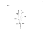
21 and 22 show another embodiment. FIG. 21 shows a bag with a receptacle, a closure, and a means for sealing the closure (including but not limited to any one of the embodiments shown in FIGS. 4-19). ing. The boundary of the sealed
図22は、図21の矢視線22−22に沿って切断したダックビル弁142の断面図である。図22に示すように、ダックビル弁142はフィルム材料から形成された2つのパネル144、146を具備している。図22に示すように、ダックビル弁142は、弁パネル144を領域141において後壁14に取着し、弁パネル146を領域140において前壁12に取着することによって受容部に取着されており、双方の接合領域は底部シームの各部分を形成している。弁パネル144、146は、図21に示す弁の各側部シーム150、148を表す点々で示された縦方向の領域において互いに接合されている。弁パネル144、146は、弁の側部シーム148、150の間の領域は互いに接合されていない。こうして、弁パネル144、146において弁の側部シームの間の部分が扁平型の通路を形成し、これを通じて受容部の内部空間の内側の空気は、内部空間を充分に、或いは、部分的に排気するまで外気中に流出可能となる。この実施形態では、すべてのシームは従来の伝導による熱融着によって形成される。
22 is a cross-sectional view of the
説明の目的で、図21、22のダックビル弁142はバッグの底部から突出しているように示されている。しかしながら、市販の製品では、使用の際に弁保護するためにダックビル弁を受容部の更に内側に組み入れることが好ましい。ダックビル弁142の外側は底部シーム領域においてパッケージの内側に溶接される。弁の内面同士は溶接されてはならない。これは、所定の位置に溶接されるときにインサートを弁内に入れることによって、或いは、フィルムの積層体から弁を作る際に、弁の内面をパッケージ用フィルムの溶融点より高い溶融点を有する非シ−ラントのポリマー材料の各層で形成することによって行うことができる。
For illustrative purposes, the
図21は、バッグの底部に取り付けられるダックビル弁示す。しかしながら、このダックビル弁142は側部シーム沿いに設けたり、或いは、バッグの隅に設けることができる。この形態では、(バッグを巻くことによって)バッグから空気を押出し、或いは、チューブを挿入して、真空掃除機を用いて空気を吸い出すことができる。
FIG. 21 shows a duckbill valve attached to the bottom of the bag. However, the
図3に示す逆止弁集成体の別の例によれば、バッグに充填してジッパーを完全に閉じる前に、底部からジッパー開口へ向けて巻き上げられる。ジッパーが完全に閉じられる前に、即ち扁平型の解放可能な手段が開放される前に、空気はジッパー開口を通じて押出される。この実施形態は扁平型の解放可能な手段とは別の逆止弁を必要としない。 According to another example of the check valve assembly shown in FIG. 3, the bag is rolled up from the bottom toward the zipper opening before filling the bag and completely closing the zipper. Air is extruded through the zipper opening before the zipper is fully closed, i.e. before the flat-type releasable means are opened. This embodiment does not require a check valve separate from the flat-type releasable means.
種々の実施形態を参照して本発明を説明したが、本発明の範囲から逸脱することなく種々の変形が可能であり、且つ、その要素を均等物に置き換え可能なことは、当業者には理解されよう。更に、本発明の基本的範囲から逸脱することなく本発明の教示に対する特別な状況を構成するように多くの改変がなされてもよい。したがって、本発明はその実施を意図した最良の態様として開示された特定の実施形態に限定されるものではなく、特許請求の範囲に含まれる全ての実施形態を含むものである。 Although the present invention has been described with reference to various embodiments, those skilled in the art will recognize that various modifications can be made without departing from the scope of the present invention, and that the elements can be replaced with equivalents. It will be understood. In addition, many modifications may be made to configure a particular situation to the teachings of the invention without departing from the basic scope thereof. Therefore, the present invention is not limited to the specific embodiment disclosed as the best mode for carrying out the invention, but includes all the embodiments included in the claims.
請求の範囲で使用されている動詞「接合されている」とは、熱および/または圧力の付与、超音波エネルギーの付与、粘着剤や結合材料から成る層の付与、粘着剤や接合片やシーラント層やビード部分等の介在の有無に関係なく、融着、接合、シール、接着等を意味する。 As used in the claims, the verb “joined” refers to application of heat and / or pressure, application of ultrasonic energy, application of a layer of adhesive or binding material, adhesive, joint piece or sealant. Regardless of the presence or absence of layers or bead portions, it means fusion, bonding, sealing, adhesion, and the like.
10 バッグ
12 前壁
14 後壁
16 弁集成体
18 開口部
20 ジッパー部品
22 ジッパー部品
32 ベース帯片
34 ベース帯片
36 塗膜(密封手段)
38 塗膜(密封手段)
40 雄型輪郭部材
42 雄型輪郭部材
44 雌型輪郭部材
46 雌型輪郭部材
48 ジッパーの内部空間(ジッパ室)
58 受容部の内部空間
DESCRIPTION OF
38 Coating film (sealing means)
40
58 Internal space of the receiving part
Claims (6)
前記第1と第2の壁によって前記開口部に、或いは、開口部の近傍にそれぞれ支持された第1と第2のジッパー部品であって、前記第1のジッパー部品は第1の閉鎖輪郭部材を具え、前記第2のジッパー部品は第2の閉鎖輪郭部材を具えており、前記第1と第2の閉鎖輪郭部材は相互に噛合可能となっているジッパー部品と、
開放状態と閉鎖状態を有し、前記受容部の内部空間が排気されたときの閉鎖状態にある間は閉じた状態を維持するように構成された扁平弁であって、該扁平弁は前記受容部の第1の側から第2の側まで延在し、閉鎖状態では前記扁平弁を通る空気遮断する扁平弁とを具備するバッグ。 A receptacle having an interior space and an opening, the receptacle comprising first and second walls joined at first and second sides and joined or connected at the bottom;
First and second zipper parts supported at or near the opening by the first and second walls, respectively, wherein the first zipper part is a first closing contour member The second zipper part comprises a second closure contour member, the first and second closure contour members being meshable with each other;
A flat valve having an open state and a closed state, and configured to maintain a closed state while the internal space of the receiving portion is in a closed state when exhausted. A flat valve that extends from a first side to a second side of the section and blocks air passing through the flat valve in a closed state.
Applications Claiming Priority (1)
| Application Number | Priority Date | Filing Date | Title |
|---|---|---|---|
| US11/173,848 US7674039B2 (en) | 2003-02-19 | 2005-07-01 | Reclosable vacuum storage bag having flat resealable means |
Publications (2)
| Publication Number | Publication Date |
|---|---|
| JP2007008589A true JP2007008589A (en) | 2007-01-18 |
| JP2007008589A5 JP2007008589A5 (en) | 2009-08-13 |
Family
ID=37054520
Family Applications (1)
| Application Number | Title | Priority Date | Filing Date |
|---|---|---|---|
| JP2006181648A Ceased JP2007008589A (en) | 2005-07-01 | 2006-06-30 | Reclosable storing bag |
Country Status (5)
| Country | Link |
|---|---|
| US (2) | US7674039B2 (en) |
| EP (1) | EP1739024A3 (en) |
| JP (1) | JP2007008589A (en) |
| KR (1) | KR101316688B1 (en) |
| CN (1) | CN100572214C (en) |
Cited By (4)
| Publication number | Priority date | Publication date | Assignee | Title |
|---|---|---|---|---|
| JP2010202224A (en) * | 2009-02-27 | 2010-09-16 | Kureha Corp | Bag body and sealing structure body |
| TWI622529B (en) * | 2017-05-31 | 2018-05-01 | Wang Yong Ming | Sealed bag and using method thereof |
| JP2019202792A (en) * | 2018-05-22 | 2019-11-28 | 株式会社生産日本社 | Bag with fitting tool |
| JP2021059365A (en) * | 2019-10-08 | 2021-04-15 | 袈裟男 小林 | Storage bag intake plug unit and storage method |
Families Citing this family (82)
| Publication number | Priority date | Publication date | Assignee | Title |
|---|---|---|---|---|
| US20110235951A1 (en) * | 1998-07-17 | 2011-09-29 | Com-Pac International, Inc. | Reclosable bag with tear open feature |
| US7270479B2 (en) * | 2001-08-24 | 2007-09-18 | S.C. Johnson Home Storage, Inc. | Venting reclosable bags |
| US8419279B2 (en) | 2004-06-29 | 2013-04-16 | The Glad Products Company | Flexible storage bag |
| US7726880B2 (en) * | 2004-06-29 | 2010-06-01 | The Glad Products Company | Flexible storage bag |
| US7389629B2 (en) * | 2004-07-23 | 2008-06-24 | Reynolds Foil Inc. | Portable vacuum pump for use with reclosable, evacuable containers |
| US7597479B2 (en) * | 2005-01-20 | 2009-10-06 | The Glad Products Company | Storage bag with fluid separator |
| US8398306B2 (en) * | 2005-11-07 | 2013-03-19 | Kraft Foods Global Brands Llc | Flexible package with internal, resealable closure feature |
| US9011003B2 (en) * | 2006-02-08 | 2015-04-21 | S.C. Johnson Home Storage, Inc. | Reclosable pouch and zipper for a reclosable pouch |
| US20080069484A1 (en) * | 2006-09-20 | 2008-03-20 | Jackman Thomas J | Polystyrene bag with polyethylene zipper |
| US20080083493A1 (en) * | 2006-10-10 | 2008-04-10 | Ridges Michael D | Reusable mechanical fastener and vacuum seal combination |
| US7857514B2 (en) | 2006-12-12 | 2010-12-28 | Reynolds Foil Inc. | Resealable closures, polymeric packages and systems and methods relating thereto |
| US7674040B2 (en) * | 2006-12-29 | 2010-03-09 | Illinois Tool Works Inc. | Reclosable bag having double closure |
| US7886412B2 (en) | 2007-03-16 | 2011-02-15 | S.C. Johnson Home Storage, Inc. | Pouch and airtight resealable closure mechanism therefor |
| US7784160B2 (en) | 2007-03-16 | 2010-08-31 | S.C. Johnson & Son, Inc. | Pouch and airtight resealable closure mechanism therefor |
| US8376614B2 (en) * | 2007-03-20 | 2013-02-19 | S.C. Johnson & Son, Inc. | Venting double zipper and reclosable storage bag using same |
| US20080304771A1 (en) * | 2007-06-05 | 2008-12-11 | Charles Harder | Vacuum storage bag with zipper |
| US7967509B2 (en) | 2007-06-15 | 2011-06-28 | S.C. Johnson & Son, Inc. | Pouch with a valve |
| US7857515B2 (en) | 2007-06-15 | 2010-12-28 | S.C. Johnson Home Storage, Inc. | Airtight closure mechanism for a reclosable pouch |
| US7946766B2 (en) | 2007-06-15 | 2011-05-24 | S.C. Johnson & Son, Inc. | Offset closure mechanism for a reclosable pouch |
| US7874731B2 (en) | 2007-06-15 | 2011-01-25 | S.C. Johnson Home Storage, Inc. | Valve for a recloseable container |
| US7887238B2 (en) | 2007-06-15 | 2011-02-15 | S.C. Johnson Home Storage, Inc. | Flow channels for a pouch |
| US9232808B2 (en) | 2007-06-29 | 2016-01-12 | Kraft Foods Group Brands Llc | Processed cheese without emulsifying salts |
| US20100205909A1 (en) * | 2007-07-24 | 2010-08-19 | Zimmerman Dean A | Storage bag |
| US20090028469A1 (en) * | 2007-07-24 | 2009-01-29 | Illinois Tool Works Inc. | Method to accurately control size, velocity, and relative position sets of reclosable mechanism |
| US20090097781A1 (en) * | 2007-10-12 | 2009-04-16 | Tang Luen-Sing | Airtight storage bag |
| CN201108117Y (en) * | 2007-11-30 | 2008-09-03 | 陈琪 | Water proof bag |
| US20090241785A1 (en) * | 2008-03-27 | 2009-10-01 | Akio Wakabayashi | Plastic, resealable elongate valve opening for a vacuum food package |
| US20110091138A1 (en) * | 2008-03-27 | 2011-04-21 | Akio Wakabayashi | Plastic, re-sealable elongated check valve application to a square, cylindrical or flat type of a vacuum food package |
| US8056471B2 (en) * | 2008-03-27 | 2011-11-15 | Akio Wakabayashi | Plastic, re-sealable elongated check valve application to a square, cylindrical or flat type of a vacuum food package |
| US20120273068A1 (en) * | 2008-03-27 | 2012-11-01 | Akio Wakabayashi | Universal air removal port u-arp |
| US20090279813A1 (en) * | 2008-05-09 | 2009-11-12 | Pokusa Kenneth C | Cohesive Reclosable Fasteners For Flexible Packages |
| WO2009146324A1 (en) * | 2008-05-28 | 2009-12-03 | Illinois Tool Works Inc. | Flexible bag with vent for pressure release |
| US8061898B2 (en) * | 2008-07-15 | 2011-11-22 | S.C. Johnson & Son, Inc. | Venting closure mechanism |
| EP2335138A4 (en) | 2008-08-15 | 2012-12-19 | Qualcomm Inc | Enhanced multi-touch detection |
| US20100147425A1 (en) * | 2008-12-17 | 2010-06-17 | Illinois Tool Works Inc. | Water-resistant asset protection bag |
| FR2942207B1 (en) * | 2009-02-17 | 2011-03-18 | S2F Flexico | CLOSURE ASSEMBLY FOR PACKAGING BAGS AND SACHETS COMPRISING SUCH AN ASSEMBLY |
| US10077139B2 (en) * | 2009-06-05 | 2018-09-18 | Weatherford Technology Holdings, Llc | Sampling bag and funnel for collection of soils, muds, or other solids or liquids for subsequent analysis of headspace gases and other content |
| US8272107B2 (en) * | 2009-10-28 | 2012-09-25 | S.C. Johnson & Son, Inc. | Vacuum-actuated closure mechanism for a resealable pouch |
| US8549713B2 (en) * | 2010-01-20 | 2013-10-08 | Illinois Tool Works Inc. | Zippered security bag |
| NZ591354A (en) | 2010-02-26 | 2012-09-28 | Kraft Foods Global Brands Llc | A low-tack, UV-cured pressure sensitive acrylic ester based adhesive for reclosable packaging |
| WO2011106486A1 (en) | 2010-02-26 | 2011-09-01 | Kraft Foods Global Brands Llc | Package having an adhesive-based reclosable fastener and methods therefor |
| US9242417B2 (en) | 2010-04-29 | 2016-01-26 | Illinois Tool Works Inc. | Zipper for security bag and method of manufacture thereof |
| US8550716B2 (en) | 2010-06-22 | 2013-10-08 | S.C. Johnson & Son, Inc. | Tactile enhancement mechanism for a closure mechanism |
| US9327875B2 (en) | 2010-10-29 | 2016-05-03 | S.C. Johnson & Son, Inc. | Reclosable bag having a loud sound during closing |
| US8469593B2 (en) | 2011-02-22 | 2013-06-25 | S.C. Johnson & Son, Inc. | Reclosable bag having a press-to-vent zipper |
| US8568031B2 (en) | 2011-02-22 | 2013-10-29 | S.C. Johnson & Son, Inc. | Clicking closure device for a reclosable pouch |
| US20130077894A1 (en) * | 2011-09-23 | 2013-03-28 | Inteplast Group, Ltd. | Sealable Bag |
| FR2988701B1 (en) * | 2012-04-03 | 2014-04-11 | S2F Flexico | CLOSURE DEVICE FOR SACHETS OR EQUIVALENTS HAVING IMPROVED TOUCH AND SOUND EFFECT, SACHET THUS OBTAINED AND METHOD OF MAKING SAME |
| CA2845896C (en) * | 2013-03-15 | 2021-06-08 | Reynolds Presto Products Inc. | False flange child resistant closure for recloseable pouch and methods |
| CA2845897C (en) | 2013-03-15 | 2022-04-12 | Reynolds Presto Products Inc. | Child resistant pouch having reclosable zipper and methods |
| USD824780S1 (en) * | 2013-09-10 | 2018-08-07 | Inteplast Group Corporation | Plastic bag with textured strip |
| CN104803106A (en) * | 2014-01-24 | 2015-07-29 | 大连竹菱包装工业有限公司 | Steaming-boiling bag capable of pre-storing food for microwave oven |
| WO2015148448A1 (en) * | 2014-03-24 | 2015-10-01 | Sio2 Medical Products, Inc. | Packaging for high purity solvents |
| CN104973319A (en) * | 2014-04-08 | 2015-10-14 | 邢晓峰 | Table tennis racket plate vacuum seal protecting bag |
| US10384835B2 (en) * | 2015-10-31 | 2019-08-20 | Com-Pac International, Inc. | Reclosable zipper having tamper evident features |
| US10759569B2 (en) * | 2014-11-01 | 2020-09-01 | Com-Pac International, Inc. | Article and method of a reclosable zipper having tamper-evident features |
| US20160137396A1 (en) * | 2014-11-13 | 2016-05-19 | Avery Dennison Retail Information Services, Llc | Commercial transportation garment bag and methods |
| JPWO2016159148A1 (en) * | 2015-03-31 | 2018-01-25 | 出光ユニテック株式会社 | Bag body with zipper tape and method for manufacturing the same |
| CN105475213B (en) * | 2015-12-11 | 2017-12-05 | 罗鹏孩 | A kind of live fish class transport packaging bag and its manufacture, application method |
| WO2017173013A1 (en) | 2016-03-30 | 2017-10-05 | Tdl Innovations, Llc. | Methods and devices for removing a tissue specimen from a patient |
| US10160586B2 (en) | 2016-06-01 | 2018-12-25 | Bemis Company, Inc. | Package film with biaxially oriented film and pattern connection layer |
| EP3478099B1 (en) | 2016-06-30 | 2020-07-22 | Philip Morris Products S.a.s. | Resealable tobacco pouch |
| US11083219B2 (en) | 2016-07-04 | 2021-08-10 | Philip Morris Products S.A. | Collapsible tobacco container |
| FI20165567A (en) * | 2016-07-06 | 2018-01-07 | Serres Oy | Device for collecting fluid from a patient and a manifold |
| WO2018156730A1 (en) | 2017-02-22 | 2018-08-30 | Cornell University | Mechanical vacuum dressing for mechanically managing, protecting and suctioning small incisional wounds |
| EP3720518A4 (en) | 2017-12-06 | 2021-09-15 | Cornell University | Manually-operated negative pressure wound therapy (npwt) bandage with improved pump efficiency, automatic pressure indicator and automatic pressure limiter |
| KR101990432B1 (en) * | 2018-02-23 | 2019-10-01 | 김영훈 | Closed container for companion animal feed and method for manufacturing the same |
| WO2020010156A1 (en) | 2018-07-06 | 2020-01-09 | Instant Systems, Inc. | Sample container with peelable seal and access port |
| CA3105782A1 (en) * | 2018-07-09 | 2020-01-16 | Instant Systems, Inc. | Self-sealing tissue storage container |
| CN108577109A (en) * | 2018-07-17 | 2018-09-28 | 惠州市鸿达泰包装用品有限公司 | The zippered bag for preventing children from opening |
| US11286086B2 (en) | 2018-12-19 | 2022-03-29 | Reynolds Presto Products Inc. | Hidden flange child resistant closure for recloseable pouch and methods |
| US11530076B2 (en) | 2018-12-19 | 2022-12-20 | Reynolds Presto Products Inc. | Hidden flange child resistant closure for recloseable pouch and methods |
| PL242136B1 (en) | 2019-02-08 | 2023-01-23 | Elplast Europe Spolka Z Ograniczona Odpowiedzialnoscia | Tamper-resistant ziplock closure and packaging with tamper-resistant ziplock closure |
| WO2021074691A1 (en) | 2019-10-18 | 2021-04-22 | Yuan Ding International (Shanghai) Co., Ltd. | Child-resistant closure system |
| WO2021074692A1 (en) * | 2019-10-18 | 2021-04-22 | Yuan Ding International (Shanghai) Co., Ltd. | Child-resistant closure system |
| US11109687B1 (en) | 2020-02-13 | 2021-09-07 | The Boeing Company | Configurable ergonomic pad |
| WO2022064281A1 (en) * | 2020-09-25 | 2022-03-31 | 科劲市场管理有限公司 | Bag container having sealing mechanism |
| EP4059393A1 (en) * | 2021-03-15 | 2022-09-21 | BSH Hausgeräte GmbH | Kitchen appliance, vacuum valve and assembly for a kitchen appliance, and method of applying a vacuum |
| US11890819B2 (en) | 2021-03-24 | 2024-02-06 | Instant Systems, Inc. | Multi-chamber container for biological materials and compounded pharmaceuticals |
| US11950591B2 (en) | 2021-06-11 | 2024-04-09 | Instant Systems, Inc. | Container with biological materials having multiple sealed portions |
| US20230054277A1 (en) * | 2021-08-12 | 2023-02-23 | Cj Cheiljedang Corporation | Pouch for retort food |
| US20230373171A1 (en) * | 2022-05-17 | 2023-11-23 | Magnum Venus Products, Inc. | Two-part bag seal |
Citations (7)
| Publication number | Priority date | Publication date | Assignee | Title |
|---|---|---|---|---|
| JPH0357025U (en) * | 1989-10-09 | 1991-05-31 | ||
| JPH0387760U (en) * | 1989-12-22 | 1991-09-06 | ||
| JPH03113972U (en) * | 1990-03-07 | 1991-11-21 | ||
| JPH07223657A (en) * | 1994-02-08 | 1995-08-22 | Teruyuki Kaneshiro | Compressible bag for containing thick bedquilt |
| JPH07277348A (en) * | 1994-04-07 | 1995-10-24 | Idemitsu Petrochem Co Ltd | Preservation bag with engaging tools, usage of the bag |
| JPH10203539A (en) * | 1997-01-17 | 1998-08-04 | Idemitsu Petrochem Co Ltd | Bag having engaging devices |
| US5829884A (en) * | 1997-06-19 | 1998-11-03 | Innoflex Incorporated | Form fill and seal package with one-way vent |
Family Cites Families (46)
| Publication number | Priority date | Publication date | Assignee | Title |
|---|---|---|---|---|
| US2779370A (en) * | 1954-08-17 | 1957-01-29 | Rogers Imp S Inc | Pouch |
| US3164186A (en) * | 1962-07-13 | 1965-01-05 | Eberhard E H Weber | Plastic container |
| US3343233A (en) * | 1966-03-11 | 1967-09-26 | Gould Russell | Slide fastener |
| US4709396A (en) * | 1985-12-24 | 1987-11-24 | John H. Harland Company | Tamper-evident envelope with indicia underlying cohesive layers |
| US4709397A (en) * | 1985-12-24 | 1987-11-24 | John H. Harland Company | Tamper-evident envelope with indicia-forming cohesive layers |
| US4759642A (en) * | 1986-08-11 | 1988-07-26 | Minigrip, Inc. | Reclosable bag especially suitable for cereal packaging, and method |
| US4944409A (en) * | 1988-02-10 | 1990-07-31 | Curwood, Inc. | Easy open package |
| US4832505A (en) * | 1988-03-11 | 1989-05-23 | Minigrip, Inc. | Tamper evident link bags |
| US4892414A (en) * | 1988-07-05 | 1990-01-09 | Minigrip, Inc. | Bags with reclosable plastic fastener having automatic sealing gasket means |
| US4905298A (en) * | 1988-12-12 | 1990-02-27 | Walor Curtis J | Resealable closure |
| US5540500A (en) * | 1994-04-25 | 1996-07-30 | Nichimen Corporation | Compressive sealed bag for compressible articles such as clothing and the same |
| KR100371671B1 (en) * | 1994-05-17 | 2003-05-17 | 이데미쓰세끼유가가꾸가부시끼가이샤 | A snap-fastener bag |
| JP2743329B2 (en) * | 1994-07-04 | 1998-04-22 | 株式会社アール | Compressed storage bag and decompression method for compressed storage bag |
| US5492411A (en) * | 1995-01-18 | 1996-02-20 | Reynolds Consumer Products Inc. | Tamper evident peelable seal |
| US5951453A (en) * | 1996-11-15 | 1999-09-14 | Innoflex Incorporated | Recloseable bag assembly and method of making same |
| US5911508A (en) * | 1997-11-10 | 1999-06-15 | Dobreski; David V. | Vented reclosable bag |
| US5839582A (en) * | 1997-12-30 | 1998-11-24 | Strong; William P. | Self vacuum storage bag |
| CA2269358C (en) * | 1998-05-21 | 2005-04-12 | Illinois Tool Works Inc. | Transverse direction zipper tape |
| US6231236B1 (en) * | 1998-07-28 | 2001-05-15 | Reynolds Consumer Products, Inc. | Resealable package having venting structure and methods |
| JP3655104B2 (en) * | 1998-08-26 | 2005-06-02 | 株式会社生産日本社 | Synthetic plastic bag with zipper |
| JP2000219252A (en) * | 1999-01-29 | 2000-08-08 | Nihon Tokkyo Kanri Co Ltd | Rice bag with zipper |
| US6360513B1 (en) * | 1999-05-11 | 2002-03-26 | Sargento Foods Inc. | Resealable bag for filling with food product(s) and method |
| US6341688B1 (en) * | 1999-12-06 | 2002-01-29 | Sandra P. Graham | Apparatus and method for denture cleaning and storage |
| US6273607B1 (en) * | 2000-01-18 | 2001-08-14 | Reynolds Consumer Products, Inc. | Reclosable package having a slider device and tamper-evident structure |
| US6350058B1 (en) * | 2000-05-04 | 2002-02-26 | Illinois Tool Works Inc. | Partially secured four flange zipper strip for transverse direction |
| JP2002193273A (en) * | 2000-12-22 | 2002-07-10 | R:Kk | Compression storage bag |
| JP3081548U (en) * | 2001-05-02 | 2001-11-09 | 株式会社アール | Compression storage bag |
| US6527444B1 (en) * | 2001-06-15 | 2003-03-04 | Reynolds Consumer Products, Inc. | Tamper-evident bag having zipper-protective cover and methods |
| US6604634B2 (en) * | 2001-07-18 | 2003-08-12 | Fu-Long Su | Receiving bag with enhanced airtight effect |
| US7270479B2 (en) * | 2001-08-24 | 2007-09-18 | S.C. Johnson Home Storage, Inc. | Venting reclosable bags |
| US6692147B2 (en) * | 2001-08-24 | 2004-02-17 | Charles Nelson | Venting reclosable bags |
| US7159282B2 (en) * | 2002-03-01 | 2007-01-09 | Pactiv Corporation | Reclosable fasteners or zippers for use with polymeric bags |
| US6691383B2 (en) * | 2002-03-07 | 2004-02-17 | Illinois Tool Works Inc. | Webless zipper |
| WO2003101850A1 (en) * | 2002-05-31 | 2003-12-11 | Aru Corporation | Deaerated storage bag |
| US6854886B2 (en) * | 2002-06-28 | 2005-02-15 | Illinois Tool Works Inc. | Watertight closure for a reclosable package |
| US6960021B2 (en) * | 2002-10-02 | 2005-11-01 | Illinois Tool Works Inc. | Reclosable packages with front panel slider-zipper assembly |
| US7036988B2 (en) * | 2003-02-19 | 2006-05-02 | Illinois Tool Works Inc. | Zipper for vacuum storage bag |
| US6814491B1 (en) * | 2003-03-27 | 2004-11-09 | Wen-Ching Tang | Sealing bag |
| US7004632B2 (en) * | 2003-03-31 | 2006-02-28 | The Glad Products Company | Ventable storage bag |
| WO2004091322A1 (en) * | 2003-04-17 | 2004-10-28 | Aru Corporation | Vacuum preservation container and vacuum preservation method of food |
| JP3677515B1 (en) * | 2004-01-10 | 2005-08-03 | 株式会社アール | Compressed bag manufacturing method and structure of compressed bag and air passage |
| US7553082B2 (en) * | 2004-08-03 | 2009-06-30 | Illinois Tool Works Inc. | Evacuable storage bag having resealable means activated by slider |
| US7674491B2 (en) * | 2004-11-24 | 2010-03-09 | Illinois Tool Works Inc. | Method for evacuating air from flexible packages |
| US7437805B2 (en) * | 2006-06-23 | 2008-10-21 | Edward Alan Berich | Reclosable storage bag closure with internal valving |
| US8376614B2 (en) * | 2007-03-20 | 2013-02-19 | S.C. Johnson & Son, Inc. | Venting double zipper and reclosable storage bag using same |
| US8061898B2 (en) * | 2008-07-15 | 2011-11-22 | S.C. Johnson & Son, Inc. | Venting closure mechanism |
-
2005
- 2005-07-01 US US11/173,848 patent/US7674039B2/en active Active
-
2006
- 2006-06-20 EP EP06253174A patent/EP1739024A3/en not_active Withdrawn
- 2006-06-23 CN CNB2006100931668A patent/CN100572214C/en not_active Expired - Fee Related
- 2006-06-28 KR KR1020060058813A patent/KR101316688B1/en active IP Right Grant
- 2006-06-30 JP JP2006181648A patent/JP2007008589A/en not_active Ceased
-
2010
- 2010-03-08 US US12/719,830 patent/US8202002B2/en not_active Expired - Lifetime
Patent Citations (7)
| Publication number | Priority date | Publication date | Assignee | Title |
|---|---|---|---|---|
| JPH0357025U (en) * | 1989-10-09 | 1991-05-31 | ||
| JPH0387760U (en) * | 1989-12-22 | 1991-09-06 | ||
| JPH03113972U (en) * | 1990-03-07 | 1991-11-21 | ||
| JPH07223657A (en) * | 1994-02-08 | 1995-08-22 | Teruyuki Kaneshiro | Compressible bag for containing thick bedquilt |
| JPH07277348A (en) * | 1994-04-07 | 1995-10-24 | Idemitsu Petrochem Co Ltd | Preservation bag with engaging tools, usage of the bag |
| JPH10203539A (en) * | 1997-01-17 | 1998-08-04 | Idemitsu Petrochem Co Ltd | Bag having engaging devices |
| US5829884A (en) * | 1997-06-19 | 1998-11-03 | Innoflex Incorporated | Form fill and seal package with one-way vent |
Cited By (6)
| Publication number | Priority date | Publication date | Assignee | Title |
|---|---|---|---|---|
| JP2010202224A (en) * | 2009-02-27 | 2010-09-16 | Kureha Corp | Bag body and sealing structure body |
| TWI622529B (en) * | 2017-05-31 | 2018-05-01 | Wang Yong Ming | Sealed bag and using method thereof |
| JP2019202792A (en) * | 2018-05-22 | 2019-11-28 | 株式会社生産日本社 | Bag with fitting tool |
| JP7020997B2 (en) | 2018-05-22 | 2022-02-16 | 株式会社生産日本社 | Bag with fitting |
| JP2021059365A (en) * | 2019-10-08 | 2021-04-15 | 袈裟男 小林 | Storage bag intake plug unit and storage method |
| JP7175454B2 (en) | 2019-10-08 | 2022-11-21 | 袈裟男 小林 | Intake plug unit for storage bag and storage method |
Also Published As
| Publication number | Publication date |
|---|---|
| US20050244083A1 (en) | 2005-11-03 |
| US8202002B2 (en) | 2012-06-19 |
| US7674039B2 (en) | 2010-03-09 |
| KR101316688B1 (en) | 2013-10-10 |
| US20100166341A1 (en) | 2010-07-01 |
| EP1739024A3 (en) | 2007-02-28 |
| KR20070003604A (en) | 2007-01-05 |
| CN1891579A (en) | 2007-01-10 |
| EP1739024A2 (en) | 2007-01-03 |
| CN100572214C (en) | 2009-12-23 |
Similar Documents
| Publication | Publication Date | Title |
|---|---|---|
| JP2007008589A (en) | Reclosable storing bag | |
| US7036988B2 (en) | Zipper for vacuum storage bag | |
| US7553082B2 (en) | Evacuable storage bag having resealable means activated by slider | |
| US7674040B2 (en) | Reclosable bag having double closure | |
| EP1879805B1 (en) | Multicompartment evacuable storage bag | |
| US8176604B2 (en) | Pouch and airtight resealable closure mechanism therefor | |
| US6983845B2 (en) | Recloseable storage bag with user-deformable air vent | |
| US7857515B2 (en) | Airtight closure mechanism for a reclosable pouch | |
| EP0983943A2 (en) | Resealable package having venting structure | |
| US20040000501A1 (en) | Recloseable storage bag with secondary closure members | |
| JP6779191B2 (en) | Storage bag with shape-retaining strips at openings and deployable bottom edge | |
| US20070092167A1 (en) | Polymeric Package With Resealable Closure And Valve, And Methods | |
| US20110085747A1 (en) | Pouch and Airtight Resealable Closure Mechanism Therefor | |
| JPH11314650A (en) | Reclosable package and zipper band therefor | |
| US5988880A (en) | Resealable closure mechanism | |
| JP2006315760A (en) | Reclosable package | |
| US8328421B2 (en) | Push-down compressible pouch with one-way valves on sides | |
| US20140093191A1 (en) | Slider for sealing and unsealing a storage bag | |
| JP2010195459A (en) | Method for manufacturing synthetic resin bag | |
| WO2019078830A1 (en) | Reusable tamper-evident bag | |
| CA2881791C (en) | Method of making a plastic film with integrated zipper closure, and plastic bag having an integrated zipper closure | |
| JP2022123814A (en) | Container and method for storing content |
Legal Events
| Date | Code | Title | Description |
|---|---|---|---|
| A521 | Written amendment |
Free format text: JAPANESE INTERMEDIATE CODE: A523 Effective date: 20090630 |
|
| A621 | Written request for application examination |
Free format text: JAPANESE INTERMEDIATE CODE: A621 Effective date: 20090630 |
|
| A521 | Written amendment |
Free format text: JAPANESE INTERMEDIATE CODE: A523 Effective date: 20100826 |
|
| A977 | Report on retrieval |
Free format text: JAPANESE INTERMEDIATE CODE: A971007 Effective date: 20111111 |
|
| A131 | Notification of reasons for refusal |
Free format text: JAPANESE INTERMEDIATE CODE: A131 Effective date: 20111122 |
|
| A521 | Written amendment |
Free format text: JAPANESE INTERMEDIATE CODE: A523 Effective date: 20120221 |
|
| A01 | Written decision to grant a patent or to grant a registration (utility model) |
Free format text: JAPANESE INTERMEDIATE CODE: A01 Effective date: 20120508 |
|
| A045 | Written measure of dismissal of application [lapsed due to lack of payment] |
Free format text: JAPANESE INTERMEDIATE CODE: A045 Effective date: 20120925 |