JP2006524611A - Pallet container - Google Patents
Pallet container Download PDFInfo
- Publication number
- JP2006524611A JP2006524611A JP2006505130A JP2006505130A JP2006524611A JP 2006524611 A JP2006524611 A JP 2006524611A JP 2006505130 A JP2006505130 A JP 2006505130A JP 2006505130 A JP2006505130 A JP 2006505130A JP 2006524611 A JP2006524611 A JP 2006524611A
- Authority
- JP
- Japan
- Prior art keywords
- tube
- rod
- cross
- section
- height
- Prior art date
- Legal status (The legal status is an assumption and is not a legal conclusion. Google has not performed a legal analysis and makes no representation as to the accuracy of the status listed.)
- Pending
Links
Images


Classifications
-
- B—PERFORMING OPERATIONS; TRANSPORTING
- B65—CONVEYING; PACKING; STORING; HANDLING THIN OR FILAMENTARY MATERIAL
- B65D—CONTAINERS FOR STORAGE OR TRANSPORT OF ARTICLES OR MATERIALS, e.g. BAGS, BARRELS, BOTTLES, BOXES, CANS, CARTONS, CRATES, DRUMS, JARS, TANKS, HOPPERS, FORWARDING CONTAINERS; ACCESSORIES, CLOSURES, OR FITTINGS THEREFOR; PACKAGING ELEMENTS; PACKAGES
- B65D77/00—Packages formed by enclosing articles or materials in preformed containers, e.g. boxes, cartons, sacks or bags
- B65D77/04—Articles or materials enclosed in two or more containers disposed one within another
- B65D77/0446—Articles or materials enclosed in two or more containers disposed one within another the inner and outer containers being rigid or semi-rigid and the outer container being of polygonal cross-section not formed by folding or erecting one or more blanks
- B65D77/0453—Articles or materials enclosed in two or more containers disposed one within another the inner and outer containers being rigid or semi-rigid and the outer container being of polygonal cross-section not formed by folding or erecting one or more blanks the inner container having a polygonal cross-section
- B65D77/0466—Articles or materials enclosed in two or more containers disposed one within another the inner and outer containers being rigid or semi-rigid and the outer container being of polygonal cross-section not formed by folding or erecting one or more blanks the inner container having a polygonal cross-section the containers being mounted on a pallet
-
- B—PERFORMING OPERATIONS; TRANSPORTING
- B65—CONVEYING; PACKING; STORING; HANDLING THIN OR FILAMENTARY MATERIAL
- B65D—CONTAINERS FOR STORAGE OR TRANSPORT OF ARTICLES OR MATERIALS, e.g. BAGS, BARRELS, BOTTLES, BOXES, CANS, CARTONS, CRATES, DRUMS, JARS, TANKS, HOPPERS, FORWARDING CONTAINERS; ACCESSORIES, CLOSURES, OR FITTINGS THEREFOR; PACKAGING ELEMENTS; PACKAGES
- B65D77/00—Packages formed by enclosing articles or materials in preformed containers, e.g. boxes, cartons, sacks or bags
- B65D77/04—Articles or materials enclosed in two or more containers disposed one within another
- B65D77/06—Liquids or semi-liquids or other materials or articles enclosed in flexible containers disposed within rigid containers
Abstract
Description
本発明は、パレットコンテナであって、液状のまたは流動性の充填物の貯蔵および輸送に用いられる、熱可塑性のプラスチックから成る肉薄の内側容器と、プラスチック容器を支持ケージとして密に取り囲む格子管フレームと、底パレットとが設けられており、該底パレットにプラスチック容器が載置しており、底パレットに格子管フレームが固く結合されており、該格子管フレームが、交差箇所で互いに溶接された鉛直なかつ水平な管ロッドから成っている形式のものに関する。 The present invention relates to a pallet container, a thin inner container made of thermoplastic plastic used for storing and transporting a liquid or fluid filling, and a lattice tube frame that closely surrounds the plastic container as a support cage. And a bottom pallet, a plastic container is placed on the bottom pallet, a lattice tube frame is firmly coupled to the bottom pallet, and the lattice tube frame is welded to each other at an intersection. Of the type consisting of vertical and horizontal tube rods.
背景技術:
パレットコンテナは、液状のまたは流動性の充填物の輸送および貯蔵のために使用される。特に高い比重(たとえば1.6g/cm3を上回る)を備えた充填物の場合、硬ばね弾性的なトラックによる悪い道路での充填されたパレットコンテナの輸送の間、格子管フレームが充填物の押寄せ力によって著しく負荷される。この動力学的な輸送負荷は格子管フレームに、常に交番する著しい撓み・ねじり応力を生ぜしめる。この撓み・ねじり応力は、相応に長い作用時間で必然的に疲労亀裂および後続のロッド破断を生ぜしめる。
Background technology:
Pallet containers are used for the transport and storage of liquid or fluid fillings. In the case of packing with a particularly high specific gravity (for example above 1.6 g / cm 3 ), during the transport of filled pallet containers on bad roads by hard spring elastic trucks, the lattice tube frame It is significantly loaded by the pushing force. This dynamic transport load creates significant alternating flexure and torsional stress on the grid tube frame. This deflection and torsional stress inevitably results in fatigue cracks and subsequent rod breaks with correspondingly long working times.
格子管フレームから成る支持ケージを備えたこのようなパレットコンテナは種々異なる構成で一般的に知られている。しかし、従来の全ての支持ケージ構成は著しい欠点を有している。 Such pallet containers with support cages made of lattice tube frames are generally known in different configurations. However, all conventional support cage configurations have significant drawbacks.
たとえばヨーロッパ特許出願公開第0755863号明細書(Fu)、ドイツ連邦共和国特許出願公開第29719830号明細書(VL)またはアメリカ合衆国特許第62244453号明細書(Mam)に基づき公知の、一貫して延びる格子管断面を備えた格子管フレームの構成は、液状の充填物の振動する押寄せ圧に基づく、輸送により生ぜしめられる撓み交番負荷時に比較的極めて迅速にロッド破断を被る。このロッド破断は常に格子管ロッドの引張領域で始まるかもしくは導入される。ロッド破断は、主に格子管ロッドの溶接された交差箇所の近傍領域に生ぜしめられる。 For example, consistently extending grid tubes known from EP 0 755 863 (Fu), DE 297 198 830 (VL) or U.S. Pat. No. 6,224,453 (Mam). The construction of the grid tube frame with a cross-section suffers rod breakage very quickly during the flexure alternating load caused by transport, based on the oscillating pushing pressure of the liquid filling. This rod break always starts or is introduced in the tensile region of the grid tube rod. Rod breakage occurs mainly in the area near the welded intersection of the grid tube rods.
たとえばヨーロッパ特許第0734967号明細書(Sch)に基づき公知の、溶接された円形管と、交差箇所の領域に設けられた著しく減じられた管横断面高さ(一貫して延びていない管断面、至るところで同じ深さの凹みもしくは減じられた管横断面高さ)とを備えた格子管フレームは、減じられた管横断面のこの領域に著しい負荷ピークが生ぜしめられ、これによって、たとえば落下試験時、輸送負荷による撓み交番応力時およびハイドロリック的な内圧テスト時の目標破断箇所もしくは目標座屈箇所が形成されているという重大な欠点を有している。交差箇所の間のロッド領域は、全ての動力学的な負荷時に著しく過度に剛性的であり、変形を吸収しない。この変形は、減じられた管横断面を備えた交差領域にしか生ぜしめられない。この場合、付加的には、溶接箇所を輸送負荷による撓み交番応力時の裂開/剥離に対して防護するために、別の横断面減少部もしくは負荷軽減領域が、全ての水平なかつ鉛直な格子管で全ての溶接箇所に強制的に設けられている(たとえばヨーロッパ特許第0734967号明細書(Sch)参照)。しかし、最も弱い管横断面が、交差された格子ロッドの溶接点のすぐ近傍領域に配置されており、これによって、永続的な交番変形が溶接点のすぐ側方に生ぜしめられることは極めて不利であると見なされる。この結果、溶接点が過負荷され、裂開される傾向にある。動力学的に負荷される構成部材を、最大の動力学的な変形が生ぜしめられるとことで真っ直ぐに溶接しないことは、溶接当業者にとって周知の設計理論である。 For example, a welded circular tube known from EP 0 734 967 (Sch) and a significantly reduced tube cross-sectional height provided in the area of the intersection (a tube section that does not extend consistently, Lattice tube frames with the same depth of depression everywhere or reduced tube cross-section height) can cause significant load peaks in this area of the reduced tube cross-section, thereby for example drop testing At the time, there is a serious drawback that a target breaking point or a target buckling point is formed at the time of a bending alternating stress due to a transportation load and a hydraulic internal pressure test. The rod area between the intersections is extremely excessively rigid at all dynamic loads and does not absorb deformation. This deformation can only occur in the intersection region with a reduced tube cross section. In this case, in addition, in order to protect the welds against tearing / peeling during flexing alternating stresses due to transport loads, a separate reduced cross-section or load-reducing area is provided for all horizontal and vertical grids. It is compulsorily provided at all welds with pipes (see, for example, European Patent No. 0734967 (Sch)). However, it is extremely disadvantageous that the weakest tube cross-section is located in the region immediately adjacent to the weld point of the crossed grid rod, and that this causes a permanent alternating deformation just to the side of the weld point. Is considered. As a result, the welding point tends to be overloaded and cleaved. It is a design theory well known to those skilled in the art of welding that the dynamically loaded components are not welded straight due to the maximum dynamic deformation.
さらに、国際公開第01/89954号パンフレットならびに国際公開第01/89955号パンフレットに基づき、格子ロッドの台形の管断面を備えたパレットコンテナが公知である。この公知のパレットコンテナでは、鉛直なかつ/または水平な管ロッドが、それぞれ交差箇所の側方に凹状成形部を有している。この部分的な凹状成形部は「撓みヒンジ」として機能するようになっていて、管ロッドの撓み抵抗モーメントを減少させるようになっている。この制限された凹状成形部が、著しく長い耐用年数を生ぜしめるものの、にもかかわらず、長時間過負荷時の一箇所に集中される応力ピークがロッド破断を完全に排除することができないことが分かった。 Furthermore, based on WO 01/89954 and WO 01/89955, a pallet container having a trapezoidal tube section of a lattice rod is known. In this known pallet container, vertical and / or horizontal tube rods each have a concave shaped part on the side of the intersection. This partial concave shaped part functions as a “flexible hinge” and reduces the flexural resistance moment of the tube rod. Although this limited concave shaped part gives a significantly longer service life, nevertheless stress peaks concentrated in one place during prolonged overloading cannot completely eliminate rod breakage. I understood.
これに対して、一貫して延びる格子管断面を備えた従来公知の格子管フレームは共通して、水平なかつ鉛直な格子管ロッドが撓み交番負荷時に全体的にもしくは全長さにわたって過度に撓み・ねじり剛性的であるという欠点を有している。結果として、ここでは、すでに比較的短い負荷時間後、疲労亀裂およびロッド破断が、特に格子管ロッドの溶接された交差箇所の近傍領域に生ぜしめられる。 On the other hand, conventionally known grid tube frames having a consistently extending grid tube cross-section are common, and horizontal and vertical grid tube rods are bent and twisted excessively or wholly over the entire length or when subjected to alternating loads. It has the disadvantage of being rigid. As a result, here already after relatively short loading times, fatigue cracks and rod breaks occur, in particular in the region near the welded intersection of the grid tube rod.
これに比べて、交差箇所で減じられた管横断面と、付加的な部分的な側方の負荷軽減領域とを備えた溶接された円形管(Sch)から成る公知の格子管フレームは、以下の欠点を有している:すなわち、
−減じられた管横断面の高さが、溶接された全ての交差箇所で等しくなければならず、異なる撓み交番負荷に適合することができない。
−凹み内で溶接された交差箇所の側方の円形横断面を備えた円形管が極めて撓み剛性的であり、撓み交番負荷時に変形しない。
−さらに、溶接された交差箇所の側方の円形管が極めてねじり剛性的であり、ねじり負荷時に変形しない。水平な格子異形ロッドが撓み交番負荷時に、この格子異形ロッドに溶接された鉛直なロッドの半径方向の運動によってねじられる。これによって、付加的な引張負荷および圧縮負荷が溶接点に生ぜしめられる。
−輸送負荷による全ての負荷もしくは応力、たとえば圧縮負荷、引張負荷、ねじり負荷が、交差箇所のすぐ側方の局所的に制限された部分的な凹み(目標座屈箇所もしくは目標破断箇所)によって専ら吸収され得る。
In comparison, a known lattice tube frame consisting of a welded circular tube (Sch) with a reduced tube cross-section at the intersection and an additional partial lateral load relief region Has the disadvantage of:
-Reduced tube cross-section height must be equal at all welded intersections and cannot accommodate different flexure alternating loads.
-A circular tube with a circular cross-section at the side of the intersection point welded in the recess is very flexible and rigid and does not deform when subjected to bending alternating loads.
-Furthermore, the welded circular tube on the side of the intersection is extremely torsionally rigid and does not deform when torsionally loaded. A horizontal grid deformed rod is twisted by the radial movement of a vertical rod welded to the grid deformed rod during flexure alternating loading. This creates additional tensile and compression loads at the weld point.
-All loads or stresses due to transport loads, such as compressive loads, tensile loads and torsional loads, are exclusively due to locally restricted partial dents (target buckling or target breaking points) just to the intersection. Can be absorbed.
課題:
本発明の課題は、公知先行技術の欠点をもはや有しておらず、揺動する液状の充填物の通常の輸送負荷に対して付加的に、充填された積み上げられたパレットコンテナ(二重積層)の積層負荷を考慮して、特に鉛直の管ロッドが疲労亀裂およびロッド破断に対して永続的に耐えることができる、溶接された管ロッドから成る格子管フレームを備えたパレットコンテナを提供することである。
Task:
The problem of the present invention is that it no longer has the disadvantages of the known prior art, but in addition to the normal transport load of oscillating liquid packing, filled stacked pallet containers (double stacking). To provide a pallet container with a lattice tube frame consisting of welded tube rods, in particular vertical tube rods can withstand permanently fatigue cracks and rod breaks It is.
この課題は、一貫して閉じられた断面を有する格子管ロッドを備えた冒頭で述べた形式のパレットコンテナにおいて、本発明によれば、少なくとも鉛直な格子ロッドが、その溶接したい交差箇所の領域にしか、より高い撓み抵抗モーメントを有しておらず、2つの交差箇所の残りの全ての領域に比較的低い撓み抵抗モーメントを有していることによって解決される。互いに溶接された管ロッドが交差箇所により高い管断面高さを有していて、したがって、高い撓み・ねじり剛性を備えた制限された領域を成しているのに対して、交差箇所以外に位置する格子ロッドは、より低い管断面高さを有していて、より低い撓み・ねじり剛性を備えた領域を成している。さらに、この場合、管ロッドが、その全長にわたって、交互に配置された互いに異なる2つの横断面、つまり、比較的大きなロッド長さにわたって、減じられた管断面高さと減じられた撓み抵抗モーメントとを備えた横断面と、より高い撓み抵抗モーメントを備えた、部分的に増加させられた管断面高さを備えた横断面とを有しており、該横断面が、溶接された交差箇所の領域にわたる比較的短いロッド長さにわたって延びていることが提案されている。 The problem is that in a pallet container of the type mentioned at the outset with a grid tube rod having a consistently closed cross section, according to the invention, at least the vertical grid rod is in the region of the intersection where it is desired to weld. However, this is solved by not having a higher deflection resistance moment and having a relatively lower deflection resistance moment in all remaining areas of the two intersections. Where tube rods welded together have a higher tube cross-section height at the intersection and thus form a limited area with high deflection and torsional stiffness, they are located outside the intersection The grid rods have a lower tube cross-sectional height and form a region with lower deflection and torsional rigidity. Furthermore, in this case, the tube rod has two different cross-sections arranged alternately over its entire length, i.e. reduced tube section height and reduced deflection resistance moment over a relatively large rod length. A cross-section with a partially increased tube cross-sectional height with a higher deflection resistance moment, the cross-section being the area of the welded intersection It has been proposed to extend over a relatively short rod length.
減じられた管断面高さと、より低い撓み抵抗モーメントとを備えた領域が、一貫して2つの交差箇所の中間に配置されている本発明による構成によって、溶接された交差箇所の領域が、有効に疲労亀裂およびロッド破断に対して防護される、すなわち、交差箇所の間の剛性的な領域における、溶接点のすぐ側方の局所的な目標撓み箇所によってではなく、弾性的なフレキシブルな領域として形成された、溶接された交差箇所の間の全領域によって防護される。 With the arrangement according to the invention in which the region with reduced tube cross-section height and lower deflection resistance moment is consistently placed in the middle of the two intersections, the welded intersection region becomes effective. Protected against fatigue cracks and rod breaks, i.e., as an elastic flexible region, not in the rigid region between the intersections, but by a local target deflection point just beside the weld Protected by the entire area formed between the welded intersections formed.
パレットコンテナは、長い方の側と短い方の側とを有している(寸法1200×1000mm)ので、最大の動力学的な変形は、論理的に管格子支持ケージの長い方の側壁に生ぜしめられる。そこには、通常、管ロッドの最も多くの破断箇所も生ぜしめられる。減じられた管断面高さを備えた領域が、管ロッド長手方向で見て、より高い撓み抵抗モーメントを備えた、より高い管断面高さを備えた領域よりも著しく長く(少なくとも2倍の長さに)形成されている管ロッドの本発明による構成によって、特に管格子支持ケージの長い方の側壁が、積層負荷に対する十分な剛性を維持したまま、全体的に振動ユニットとして弾性的に調整され、これによって、輸送振動に基づく長時間負荷時でも、もはや管ロッド破断が生ぜしめられないようになっている。 Since the pallet container has a long side and a short side (dimension 1200 × 1000 mm), the maximum dynamic deformation is logically caused on the long side wall of the tube grid support cage. Squeezed. There are usually also the most breaking points of the tube rod. The region with reduced tube cross-sectional height is significantly longer (at least twice as long as the region with higher tube cross-sectional height with higher deflection resistance moments in the longitudinal direction of the tube rod. In addition, the configuration according to the invention of the formed tube rod, in particular, allows the long side wall of the tube grid support cage to be elastically adjusted as a vibration unit as a whole, while maintaining sufficient rigidity against the laminating load. As a result, the tube rod can no longer break even under long-term loading based on transportation vibration.
通常の輸送負荷時にかつ付加的に二重積層(重畳された加算的な圧縮負荷)によって生ぜしめられる有害な撓み交番・ねじり負荷は、剛性的な交差箇所の間の弾性的な全ての領域によって吸収され、これによって、過剰に高められた局所的な応力ピークは、溶接された交差箇所にもしくは交差箇所の側方にもはや生ぜしめられない。 Harmful flexure alternating and torsional loads caused by double stacking (superimposed additional compressive loads) during normal transport loads and by all elastic regions between rigid intersections Absorbed and thereby excessively increased local stress peaks no longer occur at the welded intersection or at the sides of the intersection.
さらに、本発明による格子管ロッドは、交差箇所以外のより僅かな管断面高さを備えた長い領域でよりねじれやすい。すなわち、格子管ロッドが、多くのねじりを可能にするかもしくは同じねじり角で、より少ない圧縮応力および引張応力を、溶接された交差箇所に生ぜしめる。 Furthermore, the lattice tube rod according to the present invention is more likely to twist in a long region with a smaller tube cross-section height than at the intersection. That is, the grid tube rods allow more torsion or produce less compressive and tensile stresses at the welded intersection at the same torsion angle.
以下に、本発明の実施例を図面につき詳しく説明する。 In the following, embodiments of the invention will be described in detail with reference to the drawings.
図1には、プラスチック内側容器12と、格子管支持ケージ14と、底パレット16とを備えた本発明によるパレットコンテナ10が、正面図で下側の取出し弁と共に示してある(パレット幅1000mm)。
FIG. 1 shows a
パレットコンテナ10は、図2に側面図で示してある(パレット長さ1200mm)。この場合、同一の第2のパレットコンテナが積み上げられている。この場合、下側のパレットコンテナは、たとえばトラックでの輸送時に、液状の充填物の交互の押寄せ圧負荷に対して付加的に、上下左右に振動する積み上げられたパレットコンテナ(二重積層)の積層負荷によって著しくかつ重畳されて損なわれる。
The
プラスチック内側容器12に液状の充填物18を充填する場合には、図3aに示した流体静力学的な内圧Piの経過が生ぜしめられる。この内圧Piは上方から下方に向かって線形に増加する。この場合、液状の充填物の質量重心Sは、内側容器の高さの約1/3に位置している。このことは、動力学的な輸送負荷時に、図3bに示した、正確に質量重心Sの高さ位置における最大の側方の膨出を伴う内側容器12の交互の膨出を生ぜしめる。系の動力学的な振動時には、内側容器が「上下」する。この場合、液状の充填物の充填レベル高さが高さL(レベル)だけ変化するのに対して、側壁は、量「O」(外側),「I」(内側)だけノーマル位置を中心として弾性的に外方にかつ内方に変形し、下側底部(上下振動)は、相応して中間で量「O′」,「I′」だけ弾性的に外方にかつ内方に変形する(パレットコンテナが積層されている場合には、下側のパレットコンテナが増幅された形で変形する)。
When the plastic
図4には、パレットコンテナの長い側壁に対する付加的な積層負荷「StP」によるこの振動状態が示してある。この場合、格子ケージの管ロッドは、強制的に外方へのかつ内方へのこの弾性変形を引き受けなければならない。 FIG. 4 shows this state of vibration due to the additional stacking load “StP” on the long side wall of the pallet container. In this case, the tube rods of the lattice cage have to force this elastic deformation outward and inward.
図5には、パレットコンテナの長い側壁が平面図で示してある。外方への側壁の変形が、内方への側壁のばね弾性的な進入の約2倍の大きさであることが明らかとなる。 In FIG. 5 , the long side wall of the pallet container is shown in plan view. It becomes apparent that the outward side wall deformation is about twice as large as the inward side wall spring-elastic approach.
負荷状態を考察する場合、それぞれ最も弱い箇所もしくは最も多く負荷される領域が考慮されなければならない。最大の膨出の領域における格子ケージの長い側壁の中間に設けられた両鉛直ロッドは最大の負荷も被る。なぜならば、この両鉛直ロッドが最も多く付加的に不利な形式で、積み上げられた別のパレットコンテナの積層負荷「StP」の作用によって損なわれるからである。この場合にたいてい生ぜしめられる鉛直ロッドの損害は、下側の水平ロッドの下方の座屈または破断および全周にわたって延びる一番上側の水平ロッドとの溶接結合部の裂開であり得る。積み上げられたパレットコンテナ(図2参照)は輸送振動時に同じく、自体固有の独立した振動系を成している。底パレットは外側で全周にわたって格子フレームもしくは下側にあるパレットコンテナの一番上側の水平な格子ロッドに載置していて、この場合、同じく長い側壁の中間で最も多く下向きに十分振動し、高い程度に付加的に(ハンマ打撃のように)、下側にあるパレットコンテナの中間の鉛直ロッドを負荷する。 When considering the load state, the weakest part or the most heavily loaded area must be considered. Both vertical rods placed in the middle of the long side walls of the lattice cage in the region of maximum bulge also suffer from maximum loads. This is because the two vertical rods are in the most additional disadvantageous form and are damaged by the action of the stacking load “StP” of another stacked pallet container. The vertical rod damage usually caused in this case can be the buckling or breaking of the lower horizontal rod and the tearing of the weld joint with the uppermost horizontal rod extending all around. The stacked pallet containers (see FIG. 2) also form their own independent vibration system during transportation vibration. The bottom pallet rests on the grid frame or the uppermost horizontal grid rod on the lower pallet container on the entire circumference, and in this case, the bottom pallet also vibrates downwards most often in the middle of the long side wall, In addition to a high degree (like hammering), a vertical rod in the middle of the lower pallet container is loaded.
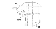
図6a、図6bおよび図6cでは、溶接された下側の水平な管ロッド22との下側の交差箇所「X」の領域における鉛直な管ロッド20が考察される。図6aには、標準位置(ノーマル状態)が示してあるのに対して、図6bには、外方への最大の撓み(量「O」)の状態が示してあり、図6cには、内方への最大の撓み(量「I」)の状態が示してある。
6a , 6b and 6c , the
外方への鉛直な管ロッドの撓み時(図6b参照)には、ロッドの外側が高い引張応力にさらされており、ロッドの内側が相応の圧縮応力にさらされている。これに対して、内方への鉛直な管ロッドの撓み時(図6c参照)には、ロッドの外側がより低い圧縮応力にさらされており、ロッドの内側が相応の引張応力にさらされている。この変形状態は動力学的な輸送負荷時に約3Hzの迅速な交番で生ぜしめられる(振動/秒=約180ヒット/分)。 When the vertical tube rod is deflected outward (see FIG. 6b ), the outside of the rod is exposed to high tensile stress and the inside of the rod is exposed to a corresponding compressive stress. In contrast, when the vertical tube rod is deflected inward (see FIG. 6c ), the outside of the rod is exposed to a lower compressive stress and the inside of the rod is exposed to a corresponding tensile stress. Yes. This deformation state occurs with a rapid alternation of about 3 Hz during dynamic transport loading (vibrations / second = about 180 hits / minute).
図4を考察する場合、鉛直な管ロッドが交差箇所「X」の下方でこの交差箇所の上方よりも強く十分に撓ませられることが明らかとなる。この原因は、鉛直な管ロッドの下側の端部が底パレット16に固く位置固定されており、この底パレット16に対する交差箇所「X」の間隔が比較的短いことである。このこともやはり、図7a、図7bおよび図7cに示した特別な負荷状況を結果的に招く。鉛直ロッドの、それぞれ異なる程度に強い撓み(上方、中間および下方;格子フレームの長い側壁の外側および中間)によって、水平な管ロッドが自体ねじられる。これによって、ねじり応力が生ぜしめられる。このねじり応力は、考察された交差箇所「X」の下側の溶接点に、作用において加算的な付加的な引張応力「Z」として現れる(図7a参照)。このことは、第1に疲労亀裂もしくはロッド破断を生ぜしめ得る(図7b参照)かまたは、たとえば円形の管断面の場合には、溶接点の裂開/剥離を生ぜしめ得る(図7c参照)。
Considering FIG. 4 , it becomes clear that the vertical tube rod is deflected more strongly and sufficiently below the intersection “X” than above the intersection. This is because the lower end of the vertical tube rod is firmly fixed to the
図8aおよび図8bには、生ぜしめられる引張/圧縮応力を説明するために、モデルとして、T支持体が、撓み負荷時の所属の応力状態で示してある。中立の繊維層(=弾性的な線)は撓み梁(T支持体)の面重心SFを通って延びている。対称的な横断面(たとえば円形管、正方形横断面または長方形横断面)の場合には、中立の繊維層が撓み梁の中心に位置している。なぜならば、そこには面重心も位置しているからである。図8aで明らかとなるように、面重心SFはT支持体の場合に下方にT支持体の広幅側に向かって移動させられている。この結果、T支持体の抵抗モーメントが広幅側における下側の縁繊維に対して、狭幅側における上側の縁繊維よりも大きく、したがって、応力が下方で上方よりも小さいことが生ぜしめられる。通常、ほぼあらゆる材料は圧力で張力よりも著しく高く負荷され得る。すなわち、危険な引張応力よりも高い圧縮応力が生ぜしめられる。このことは、動力学的に負荷される構成部材の適切な組付け位置に対して重要である。 In FIGS. 8a and 8b , the T support is shown as a model in the associated stress state at the time of deflection load, in order to explain the tensile / compressive stress produced. Extend through the surface center of gravity S F of the fibrous layer of neutral (= elastic line) deflection beam (T support). In the case of a symmetric cross section (for example a circular tube, a square cross section or a rectangular cross section), the neutral fiber layer is located at the center of the flexure beam. This is because the center of gravity of the surface is also located there. As is clear from FIG. 8a , the center of gravity SF is moved downward toward the wide side of the T support in the case of the T support. As a result, the resistance moment of the T support is greater for the lower edge fibers on the wide side than for the upper edge fibers on the narrow side, and therefore the stress is lower and lower than above. Usually, almost any material can be loaded significantly higher than tension in pressure. That is, a compressive stress higher than a dangerous tensile stress is generated. This is important for proper assembly position of the dynamically loaded component.
T支持体に類似して、すなわち、近似して、図9aおよび図9bで明らかなように、(広幅側と狭幅側とを備えた)台形断面を備えた管ロッドが挙げられる。台形断面の領域における鉛直な管ロッドの外方への最大の撓みを伴う格子フレームの長い側に対する不利な負荷事例を考察する場合には、交差領域に溶接点が配置された管ロッドの外側の広幅側に、鉛直な管ロッドの、内方に向けられた狭幅側に対する圧縮応力よりも低い引張応力が生ぜしめられる(図9b参照):σZ<σD。 A tube rod with a trapezoidal cross-section (with a wide side and a narrow side) can be mentioned, similar to a T-support, i.e., approximating, as can be seen in FIGS. 9a and 9b . When considering adverse loading cases on the long side of the grid frame with maximum outward deflection of the vertical tube rod in the trapezoidal cross-sectional area, the outside of the tube rod with weld points located in the intersecting region On the wide side, a tensile stress is generated which is lower than the compressive stress on the narrow side of the vertical tube rod directed inward (see FIG. 9b): σ Z <σ D.
ここから明らかとなるように、有利な台形断面の領域における鉛直な管ロッドは、あたかも対称的な管横断面、たとえば円形管が付与されているかのように、外方への臨界的な撓み時に、より僅かな危険な引張応力を被る(T支持体モデル)。 As will be clear from this, the vertical tube rod in the region of advantageous trapezoidal cross-section is subject to critical deflection outwards as if a symmetrical tube cross-section, e.g. a circular tube, is applied. , Under a slightly less dangerous tensile stress (T support model).
図10には、本発明による構成が示してある。格子管ロッドの基本断面は、ここでは、正方形の断面(縁長さは、たとえば16mm=高い長方形断面)として形成されている。交差領域には、水平なかつ鉛直な管ロッド20,22が、たとえば16mmの大きな管断面高さ「H」を有しているのに対して、交差箇所以外の管ロッドの自由領域には、たとえば12mmの減じられたより低い管断面高さ「h」を備えた低い長方形断面が設けられている。この場合、「H」から「h」への管断面高さの減少は、それぞれ水平なかつ鉛直な管ロッドが互いに溶接されている側から行われている。
FIG. 10 shows a configuration according to the present invention. Here, the basic cross section of the lattice tube rod is formed as a square cross section (edge length is, for example, 16 mm = high rectangular cross section). In the intersecting region, the horizontal and
本発明による有利な構成は図11に示してある。格子管ロッドの基本断面は、ここでは、台形断面である。交差領域における水平なかつ鉛直な管ロッド20,22は同じく、16mmの大きな管断面高さ「H」と、交差箇所以外の管ロッドの自由領域に、約12mmの減じられたより低い管断面高さ「h」とを、ほぼ長方形の横断面(低い長方形断面)において有している。しかし、この場合、「H」から「h」への管断面高さの減少は、それぞれ溶接点と反対の側に位置する側から行われた。このことは、水平なかつ鉛直な管ロッドが互いに溶接されている側が線形に一貫して延びていて、変形させられていないという利点を有している。これによって、外方への鉛直な管ロッドの撓み時(量「O])の最大の引張応力の高さにおける著しい変化もしくは飛躍は生ぜしめられない。
An advantageous arrangement according to the invention is shown in FIG . Here, the basic cross section of the lattice tube rod is a trapezoidal cross section. The horizontal and
ここには、鉛直な管ロッド20の下側の領域に別の有利な構成が示してある。この構成では、「H」から「h」への管断面高さの減少がそれぞれ両側(溶接された側および溶接点と反対の側)から行われた。これによって、製造技術的な利点が生ぜしめられ、片側の変形応力は生ぜしめられない。さらに、管断面高さの両側の減少時には、側あたり僅かな高さ、すなわち、高さ差の半分(H−h)/2(側あたり、たとえば2〜3mm)が高い基本断面に凹状成形されさえすればよい。
Here, another advantageous configuration is shown in the region below the
図12には、高い基本断面としての有利な台形の管断面が、溶接された交差箇所における本発明による異形管格子ロッドの横断面図で示してある(大きな管断面高さ)。この場合、高さ「H」は16mmであり、幅は約18mmである。図13には、低い管断面高さ「h」を備えた溶接された交差箇所以外の図12に示した異形管格子ロッドの横断面図が示してある。この場合、高さ「h」は12mmであり、幅は約20mmである。この場合、「H」から「h」への管断面高さの減少は、台形の基本断面の広幅側から行われている。図14には、低い管断面高さ「h」を備えた溶接された交差箇所以外の異形管格子ロッドの別の横断面が示してある。この場合、高さ「h」は12mmであり、幅は約19mmである。この場合、「H」から「h」への管断面高さの減少は、台形の基本断面の狭幅側から行われている。断面はほぼ長方形である。 In FIG. 12 , an advantageous trapezoidal tube section as a high basic section is shown in a cross-sectional view of a deformed tube grid rod according to the invention at a welded intersection (large tube section height). In this case, the height “H” is 16 mm and the width is about 18 mm. FIG. 13 shows a cross-sectional view of the deformed tube lattice rod shown in FIG. 12 except for the welded intersection with a low tube cross-section height “h”. In this case, the height “h” is 12 mm and the width is about 20 mm. In this case, the reduction of the tube cross-section height from “H” to “h” is performed from the wide side of the trapezoidal basic cross-section. FIG. 14 shows another cross-section of a deformed tube lattice rod other than a welded intersection with a low tube section height “h”. In this case, the height “h” is 12 mm and the width is about 19 mm. In this case, the reduction of the tube cross-section height from “H” to “h” is performed from the narrow side of the trapezoidal basic cross-section. The cross section is almost rectangular.
高さにおいて減じられた管横断面の別のバージョンは図15に示してある。この場合、台形の基本断面の管断面高さHを減じるために、同じく狭幅側が内向きで管横断面に凹状成形された。同じくほぼ長方形の断面が得られる。 Another version of the tube cross-section reduced in height is shown in FIG . In this case, in order to reduce the tube cross-sectional height H of the trapezoidal basic cross-section, the concave side was similarly formed in the tube cross-section with the narrow side inward. Similarly, a substantially rectangular cross section is obtained.
高さにおいて減じられた管横断面の別のバージョンは図16に示してある。この場合、管断面高さHの減少は、管横断面への内向きでの台形の基本断面の、斜めに延びる反対の側に位置する両側壁の凹状成形によって行われた。 Another version of the tube cross-section reduced in height is shown in FIG . In this case, the reduction in the tube cross-section height H was achieved by concave molding of the side walls located on the opposite side of the diagonally extending basic cross section of the trapezoidal inward to the tube cross-section.
図17には、交差箇所にわたる台形の基本断面Hと、交差箇所の間の高さ減少させられた長方形の管ロッド断面hとを備えた有利な構成が示してある。「H」から「h」への管断面高さの減少は、水平なかつ鉛直な管ロッド20,22において、それぞれ溶接点と反対の側から行われた。
FIG. 17 shows an advantageous configuration with a trapezoidal basic cross section H across the intersections and a rectangular tube rod section h with a reduced height between the intersections. The reduction of the tube cross-section height from “H” to “h” was performed on the horizontal and
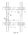
図18には、4つの交差箇所を備えた格子フレームの部分が外側から見た平面図で示してある。水平なかつ鉛直な管格子ロッドは交差箇所あたり4つの溶接点によって(管格子ロッドの、重なり合って位置する交差する外側リブによって)互いに溶接されている。 FIG. 18 shows a plan view of a portion of a lattice frame having four intersections as seen from the outside. The horizontal and vertical tube grid rods are welded together by four weld points per intersection (by the overlapping outer ribs of the tube grid rods located one on top of the other).
低い管断面高さhを備えた、2つの交差箇所の間の全管ロッド長さLhは、大きな管断面高さH=基本断面から平坦にされ(たかもしくはローラレベリングされたか、扁平にされたか、凹状成形され)、100mm〜260mmの間、有利には約130mmに寸法設定されている。 The total tube rod length L h between two intersections with a low tube cross-section height h is flattened (or roller leveled or flattened) from a large tube cross-section height H = basic cross-section Or is concavely shaped) and is dimensioned between 100 mm and 260 mm, preferably about 130 mm.
高い管断面高さHを備えた、交差箇所にわたって延びる比較的短い管ロッド長さLHは、40mm〜120mmの間、有利には約60mm(=3×20mmの管ロッド幅)に寸法設定されている。 The relatively short tube rod length L H extending across the intersection with a high tube section height H is dimensioned between 40 mm and 120 mm, preferably about 60 mm (= 3 × 20 mm tube rod width). ing.
これに相応して、図19には、内側から(鉛直な管ロッド20の張出し部Hを)見た図が示してある。 Correspondingly, FIG. 19 shows a view from the inside (the overhanging portion H of the vertical tube rod 20).
高い撓み剛性(曲げ剛性)を、溶接された交差箇所の領域に達成すると同時により低い撓み剛性もしくはより高い弾性を交差箇所以外の格子ロッドの全領域に達成するために、種々異なる有利な手段を実現することができる。1つには、水平な管格子ロッド22が交差箇所以外に、鉛直な管格子ロッド20と同じ管断面高さを交差箇所以外に有しているかまたは鉛直な管格子ロッド20よりも低い管断面高さを交差箇所以外に有していることを提案することができる。もう1つには、鉛直な管格子ロッド20が交差領域の内部に、水平な管格子ロッド22と同じ管断面高さを有しているかまたは水平な管格子ロッド22よりも高い管断面高さを有していることを提案することができる。
In order to achieve a high flexural rigidity (bending stiffness) in the area of the welded intersection, while at the same time achieving a lower flexural rigidity or higher elasticity in the entire area of the grid rod other than the intersection, different and advantageous means can be used. Can be realized. For example, the horizontal
さらに、鉛直なまたは/かつ水平な管格子ロッド20,22は、交差領域の内部で各管ロッド20,22の長さLHにわたって管ロッド長手方向に少なくとも2倍の管ロッド幅(2×20mm)から最大6倍の管ロッド幅、有利には約3倍の管ロッド幅まで延びていてよい。交差領域以外の鉛直なまたは/かつ水平な管格子ロッド20,22の低いロッド断面(低い管断面高さ)に対して、管ロッド長手方向で少なくとも3倍の管ロッド幅(3×20mm)から最大8倍の管ロッド幅、有利には約6倍の管ロッド幅までの各管ロッド20,22の長さLhが推奨される。
Furthermore, the vertical or / and horizontal
より低い管断面高さhが、一貫して高い管断面高さHを備えた出発異形ロッドの部分的に両側の側方の凹状成形(ローラ掛け)によって形成されていると、製造技術的に有利である。 If the lower tube cross-section height h is formed by a concave recess (rolling) on both sides of the starting deformed rod with a consistently high tube cross-section height H, it is technically It is advantageous.
管断面高さHの減少の別の可能性は、出発異形ロッド(基本断面)の互いに反対の2つの側の部分的に片側のまたは/かつ両側の凹状成形(ローラ掛け、ローラ押込み)によって行われてよい。 Another possibility for the reduction of the tube cross-section height H is achieved by partially forming unilaterally and / or on both sides of the starting deformed rod (basic cross-section) opposite to each other (rolling, roller indentation). You may be broken.
これらの手段は、個々にまたは有利な組合せで、格子壁平面の全弾性特性の著しい改善および溶接された交差箇所領域の負荷軽減を生ぜしめ、長く続く強い撓み交番負荷時、たとえば悪い道程でのトラック輸送の際の充填されたパレットコンテナの異常な輸送負荷時に、ロッド破断感度(=疲労破断)の著しい低下を招く。 These measures, individually or in advantageous combinations, result in a significant improvement in the total elastic properties of the grid wall plane and a reduction in the load on the welded intersection area, during long lasting strong alternating loads, for example on bad roads. The rod breakage sensitivity (= fatigue breakage) is significantly reduced at the time of abnormal transportation load of the filled pallet container during truck transportation.
鉛直なまたは/かつ水平な管格子ロッドでは、管断面高さにおける違いが、以下の構成において:すなわち、
1.管格子ロッド長さにわたって異なって、
2.鉛直な管格子ロッドにのみ、
3.鉛直なかつ水平な管格子ロッドに、または/かつ
4.管格子ロッドが、生ぜしめられる負荷に相応して必要となるところで、部分的にのみ管格子ロッドに実現されて
存在し得る。
For vertical or / and horizontal tube grid rods, the difference in tube cross-section height is in the following configuration:
1. Different over tube grid rod length,
2. Only for vertical tube grid rods,
3. 3. to vertical and horizontal tube grid rods, and / or Where a tube grid rod is required corresponding to the load produced, it can only be partly realized in the tube grid rod.
図20aには、本発明による有利な構成における鉛直な管ロッド20がノーマル位置で示してある。動力学的な負荷時には、管ロッド20がこのノーマル位置を中心として振動し、図20bにより外方にかつ図20cにより内方に十分撓む。
In FIG. 20a , a
管ロッドのこの本発明による構成によって、公知のパレットコンテナに比べて、生ぜしめられる応力ピークが、最も多く負荷される鉛直な格子ロッドの疲労亀裂および脆弱破断を最短の時間で生ぜしめるように高い値を達成することなしに、特に格子フレームの長い側壁に対して、外方への最大の弾性的な撓みのより大きな量「O」と、内方への最大の弾性的な撓みのより大きな量「I」とが可能となる。 Due to this configuration of the tube rod according to the invention, the stress peaks produced are high compared to known pallet containers so that the most heavily loaded vertical lattice rods will generate fatigue cracks and brittle fractures in the shortest time. Without achieving the value, especially for the long side walls of the grid frame, a larger amount of maximum elastic deflection outwardly “O” and a maximum of maximum elastic deflection inward The quantity “I” is possible.
したがって、低い異形ロッド高さの多くの「長い」領域を備えた格子ケージが、従来のパレットコンテナの公知の格子ケージに比べて自体著しく弾性的なばね系であると認められる。 Thus, it is recognized that a lattice cage with many “long” regions with low profile rod height is itself a significantly more elastic spring system compared to known lattice cages of conventional pallet containers.
10 パレットコンテナ、 12 プラスチック内側容器、 14 格子管支持ケージ、 16 底パレット、 18 充填物、 20 管ロッド、 22 管ロッド、 H,h 管断面高さ、 I,I′ 量、 L 高さ、 LH,Lh 管ロッド長さ、 O,O′ 量、 Pi 内圧、 S 質量重心、 SF 面重心、 StP 積層負荷、 X 交差箇所、 Z 引張応力、 σD 圧縮応力、 σZ 引張応力 10 Pallet container, 12 Plastic inner container, 14 Lattice tube support cage, 16 Bottom pallet, 18 Filling, 20 Tube rod, 22 Tube rod, H, h Tube cross section height, I, I 'amount, L height, L H, L h tube rod length, O, O 'amount, Pi pressure, S the center of mass, S F face centroid, StP stacked load, X intersection, Z tensile stress, sigma D compressive stress, sigma Z tensile stress
Claims (12)
少なくとも鉛直な管ロッド(20)が、それぞれ異なる管断面高さを備えた領域を有しており、低い方の管断面高さ(h)を備えた領域が、一貫して線形に延びて交差箇所の間にもしくは交差箇所以外に設けられており、高い方の管断面高さ(H)を備えた領域が、交差箇所にもしくは交差箇所の内部に設けられていることを特徴とする、パレットコンテナ。 A pallet container (10) comprising a thin inner container (12) made of thermoplastic plastic used for storing and transporting a liquid or fluid filling, and a plastic container (12) as a support cage. A grid tube frame (14) and a bottom pallet (16) are provided, and a plastic container (12) is placed on the bottom pallet (16), and the grid tube frame is placed on the bottom pallet (16). (14) are tightly coupled and the grid tube frame (14) has vertical and horizontal tube rods (20, 22) welded together at the intersections,
At least the vertical tube rods (20) have regions with different tube cross-section heights, and regions with lower tube cross-section heights (h) consistently extend linearly and intersect. The pallet is provided between the points or other than the crossing points, and the region having the higher pipe cross section height (H) is provided at the crossing points or inside the crossing points. container.
Applications Claiming Priority (2)
| Application Number | Priority Date | Filing Date | Title |
|---|---|---|---|
| DE20306550 | 2003-04-25 | ||
| PCT/EP2004/003975 WO2004096660A1 (en) | 2003-04-25 | 2004-04-15 | Pallet container |
Publications (2)
| Publication Number | Publication Date |
|---|---|
| JP2006524611A true JP2006524611A (en) | 2006-11-02 |
| JP2006524611A5 JP2006524611A5 (en) | 2007-05-31 |
Family
ID=33395142
Family Applications (1)
| Application Number | Title | Priority Date | Filing Date |
|---|---|---|---|
| JP2006505130A Pending JP2006524611A (en) | 2003-04-25 | 2004-04-15 | Pallet container |
Country Status (15)
| Country | Link |
|---|---|
| US (1) | US8408413B2 (en) |
| EP (1) | EP1618047B1 (en) |
| JP (1) | JP2006524611A (en) |
| KR (1) | KR101125722B1 (en) |
| CN (1) | CN100480148C (en) |
| AT (1) | ATE329853T1 (en) |
| AU (1) | AU2004233969B2 (en) |
| BR (1) | BRPI0409784B1 (en) |
| CA (1) | CA2523359A1 (en) |
| DE (2) | DE112004000700B4 (en) |
| ES (1) | ES2267063T3 (en) |
| IL (1) | IL171576A (en) |
| MX (1) | MXPA05011494A (en) |
| WO (1) | WO2004096660A1 (en) |
| ZA (1) | ZA200508674B (en) |
Cited By (2)
| Publication number | Priority date | Publication date | Assignee | Title |
|---|---|---|---|---|
| JP2012056636A (en) * | 2010-09-06 | 2012-03-22 | Protechna Sa | Transport and storage container for liquids |
| JP2020527516A (en) * | 2017-07-13 | 2020-09-10 | マウザー−ヴェルケ ゲゼルシャフト ミット ベシュレンクテル ハフツングMauser−Werke GmbH | Pallet container |
Families Citing this family (5)
| Publication number | Priority date | Publication date | Assignee | Title |
|---|---|---|---|---|
| EP2301860B1 (en) * | 2009-09-29 | 2013-05-29 | Greif International Holding BV. | Pallet container for liquids |
| DE102011013192A1 (en) * | 2011-03-05 | 2012-09-06 | Dietmar Przytulla | pallet container |
| DE202012001726U1 (en) | 2012-02-20 | 2012-06-14 | Dietmar Przytulla | pallet container |
| US20160326728A1 (en) * | 2015-05-08 | 2016-11-10 | gotügo, LLC | Outdoor water system |
| JP2022553001A (en) * | 2019-10-18 | 2022-12-21 | マウザー-ヴェルケ ゲゼルシャフト ミット ベシュレンクテル ハフツング | pallet container |
Citations (2)
| Publication number | Priority date | Publication date | Assignee | Title |
|---|---|---|---|---|
| JP2000177794A (en) * | 1998-12-17 | 2000-06-27 | Ishikawajima Harima Heavy Ind Co Ltd | Vibration-isolating structure for tank |
| JP2001341741A (en) * | 2000-05-25 | 2001-12-11 | Mauser Werke Gmbh & Co Kg | Pallet container |
Family Cites Families (6)
| Publication number | Priority date | Publication date | Assignee | Title |
|---|---|---|---|---|
| DE19511723C1 (en) | 1995-03-30 | 1996-08-29 | Protechna Sa | Pallet container |
| DK0755863T3 (en) * | 1995-07-25 | 1998-01-12 | Fustiplast Spa | Cradle cage for pallets |
| NL1004470C2 (en) * | 1996-11-07 | 1998-05-19 | Leer Koninklijke Emballage | Tube. |
| EP0916592B1 (en) * | 1997-11-04 | 2001-10-04 | Royal Packaging Industry Van Leer N.V. | Pallet container with grid support structure |
| IT243827Y1 (en) * | 1998-03-05 | 2002-03-06 | Mamor Spa | REFINED TANK, PARTICULARLY SUITABLE FOR CONTAINMENT AND TRANSPORT OF LIQUIDS |
| CN1221448C (en) | 2000-05-25 | 2005-10-05 | 毛瑟工厂责任有限及两合公司 | Palette container |
-
2004
- 2004-04-15 CA CA002523359A patent/CA2523359A1/en not_active Abandoned
- 2004-04-15 AT AT04727514T patent/ATE329853T1/en not_active IP Right Cessation
- 2004-04-15 BR BRPI0409784A patent/BRPI0409784B1/en active IP Right Grant
- 2004-04-15 EP EP04727514A patent/EP1618047B1/en not_active Revoked
- 2004-04-15 DE DE112004000700.3T patent/DE112004000700B4/en not_active Expired - Lifetime
- 2004-04-15 JP JP2006505130A patent/JP2006524611A/en active Pending
- 2004-04-15 DE DE502004000779T patent/DE502004000779D1/en not_active Revoked
- 2004-04-15 CN CNB200480018062XA patent/CN100480148C/en not_active Expired - Lifetime
- 2004-04-15 MX MXPA05011494A patent/MXPA05011494A/en active IP Right Grant
- 2004-04-15 KR KR1020057020265A patent/KR101125722B1/en active IP Right Grant
- 2004-04-15 AU AU2004233969A patent/AU2004233969B2/en not_active Expired
- 2004-04-15 WO PCT/EP2004/003975 patent/WO2004096660A1/en active IP Right Grant
- 2004-04-15 ES ES04727514T patent/ES2267063T3/en not_active Expired - Lifetime
-
2005
- 2005-06-21 US US11/157,737 patent/US8408413B2/en active Active - Reinstated
- 2005-10-26 IL IL171576A patent/IL171576A/en active IP Right Grant
- 2005-10-26 ZA ZA200508674A patent/ZA200508674B/en unknown
Patent Citations (2)
| Publication number | Priority date | Publication date | Assignee | Title |
|---|---|---|---|---|
| JP2000177794A (en) * | 1998-12-17 | 2000-06-27 | Ishikawajima Harima Heavy Ind Co Ltd | Vibration-isolating structure for tank |
| JP2001341741A (en) * | 2000-05-25 | 2001-12-11 | Mauser Werke Gmbh & Co Kg | Pallet container |
Cited By (3)
| Publication number | Priority date | Publication date | Assignee | Title |
|---|---|---|---|---|
| JP2012056636A (en) * | 2010-09-06 | 2012-03-22 | Protechna Sa | Transport and storage container for liquids |
| JP2020527516A (en) * | 2017-07-13 | 2020-09-10 | マウザー−ヴェルケ ゲゼルシャフト ミット ベシュレンクテル ハフツングMauser−Werke GmbH | Pallet container |
| JP7155232B2 (en) | 2017-07-13 | 2022-10-18 | マウザー-ヴェルケ ゲゼルシャフト ミット ベシュレンクテル ハフツング | pallet container |
Also Published As
| Publication number | Publication date |
|---|---|
| CN100480148C (en) | 2009-04-22 |
| ZA200508674B (en) | 2006-07-26 |
| IL171576A (en) | 2009-12-24 |
| DE502004000779D1 (en) | 2006-07-27 |
| CA2523359A1 (en) | 2004-11-11 |
| EP1618047B1 (en) | 2006-06-14 |
| KR101125722B1 (en) | 2012-03-27 |
| BRPI0409784B1 (en) | 2016-08-23 |
| CN1812917A (en) | 2006-08-02 |
| WO2004096660A1 (en) | 2004-11-11 |
| AU2004233969B2 (en) | 2010-03-04 |
| KR20060006941A (en) | 2006-01-20 |
| US8408413B2 (en) | 2013-04-02 |
| AU2004233969A1 (en) | 2004-11-11 |
| DE112004000700B4 (en) | 2015-02-26 |
| ATE329853T1 (en) | 2006-07-15 |
| MXPA05011494A (en) | 2005-12-15 |
| DE112004000700A5 (en) | 2007-09-06 |
| ES2267063T3 (en) | 2007-03-01 |
| US20050247710A1 (en) | 2005-11-10 |
| EP1618047A1 (en) | 2006-01-25 |
| BRPI0409784A (en) | 2006-05-30 |
Similar Documents
| Publication | Publication Date | Title |
|---|---|---|
| US8424702B2 (en) | Pallet container for liquids | |
| US8863978B2 (en) | Pallet container | |
| CA2172937A1 (en) | Pallet container | |
| US7140490B2 (en) | Pallet container | |
| US8408413B2 (en) | Pallet container | |
| US20060201401A1 (en) | Impact-resisting pallet having metal stay | |
| KR100772568B1 (en) | Pallet container | |
| US20060201399A1 (en) | Pallet having impact resisting plastic top | |
| KR101212841B1 (en) | S-type Slit Damper for Frame Structure | |
| KR20190012766A (en) | Built-Up Beam | |
| JP5651198B2 (en) | Beam support structure of building | |
| US20050028478A1 (en) | Joining structure | |
| WO2012119702A2 (en) | Pallet container | |
| JP6884374B2 (en) | tank | |
| JP2750098B2 (en) | H-shaped beam reinforcement structure | |
| JP5362463B2 (en) | Sleeper | |
| JP7155232B2 (en) | pallet container | |
| RU2759268C1 (en) | Container for transportation and storage of liquids | |
| KR20030015251A (en) | Palette container | |
| JP2002205793A (en) | Internal reinforcing structure of tank |
Legal Events
| Date | Code | Title | Description |
|---|---|---|---|
| A521 | Request for written amendment filed |
Free format text: JAPANESE INTERMEDIATE CODE: A523 Effective date: 20070330 |
|
| A621 | Written request for application examination |
Free format text: JAPANESE INTERMEDIATE CODE: A621 Effective date: 20070330 |
|
| A977 | Report on retrieval |
Free format text: JAPANESE INTERMEDIATE CODE: A971007 Effective date: 20090727 |
|
| A131 | Notification of reasons for refusal |
Free format text: JAPANESE INTERMEDIATE CODE: A131 Effective date: 20090805 |
|
| A601 | Written request for extension of time |
Free format text: JAPANESE INTERMEDIATE CODE: A601 Effective date: 20091105 |
|
| A602 | Written permission of extension of time |
Free format text: JAPANESE INTERMEDIATE CODE: A602 Effective date: 20091112 |
|
| A601 | Written request for extension of time |
Free format text: JAPANESE INTERMEDIATE CODE: A601 Effective date: 20091201 |
|
| A602 | Written permission of extension of time |
Free format text: JAPANESE INTERMEDIATE CODE: A602 Effective date: 20091208 |
|
| A601 | Written request for extension of time |
Free format text: JAPANESE INTERMEDIATE CODE: A601 Effective date: 20100104 |
|
| A602 | Written permission of extension of time |
Free format text: JAPANESE INTERMEDIATE CODE: A602 Effective date: 20100112 |
|
| A521 | Request for written amendment filed |
Free format text: JAPANESE INTERMEDIATE CODE: A523 Effective date: 20100201 |
|
| A131 | Notification of reasons for refusal |
Free format text: JAPANESE INTERMEDIATE CODE: A131 Effective date: 20100415 |
|
| A601 | Written request for extension of time |
Free format text: JAPANESE INTERMEDIATE CODE: A601 Effective date: 20100712 |
|
| A602 | Written permission of extension of time |
Free format text: JAPANESE INTERMEDIATE CODE: A602 Effective date: 20100720 |
|
| A601 | Written request for extension of time |
Free format text: JAPANESE INTERMEDIATE CODE: A601 Effective date: 20100812 |
|
| A602 | Written permission of extension of time |
Free format text: JAPANESE INTERMEDIATE CODE: A602 Effective date: 20100819 |
|
| A601 | Written request for extension of time |
Free format text: JAPANESE INTERMEDIATE CODE: A601 Effective date: 20100915 |
|
| A602 | Written permission of extension of time |
Free format text: JAPANESE INTERMEDIATE CODE: A602 Effective date: 20100924 |
|
| A521 | Request for written amendment filed |
Free format text: JAPANESE INTERMEDIATE CODE: A523 Effective date: 20101015 |
|
| A02 | Decision of refusal |
Free format text: JAPANESE INTERMEDIATE CODE: A02 Effective date: 20101210 |
|
| RD04 | Notification of resignation of power of attorney |
Free format text: JAPANESE INTERMEDIATE CODE: A7424 Effective date: 20101228 |