JP2006521210A - Method for connecting channel-shaped connecting member and structural sandwich plate member by welding - Google Patents
Method for connecting channel-shaped connecting member and structural sandwich plate member by welding Download PDFInfo
- Publication number
- JP2006521210A JP2006521210A JP2006505891A JP2006505891A JP2006521210A JP 2006521210 A JP2006521210 A JP 2006521210A JP 2006505891 A JP2006505891 A JP 2006505891A JP 2006505891 A JP2006505891 A JP 2006505891A JP 2006521210 A JP2006521210 A JP 2006521210A
- Authority
- JP
- Japan
- Prior art keywords
- sandwich plate
- structural sandwich
- connecting member
- plate member
- structural
- Prior art date
- Legal status (The legal status is an assumption and is not a legal conclusion. Google has not performed a legal analysis and makes no representation as to the accuracy of the status listed.)
- Pending
Links
Images

Classifications
-
- B—PERFORMING OPERATIONS; TRANSPORTING
- B23—MACHINE TOOLS; METAL-WORKING NOT OTHERWISE PROVIDED FOR
- B23K—SOLDERING OR UNSOLDERING; WELDING; CLADDING OR PLATING BY SOLDERING OR WELDING; CUTTING BY APPLYING HEAT LOCALLY, e.g. FLAME CUTTING; WORKING BY LASER BEAM
- B23K33/00—Specially-profiled edge portions of workpieces for making soldering or welding connections; Filling the seams formed thereby
- B23K33/002—Crimping or bending the workpieces at the joining area
-
- B—PERFORMING OPERATIONS; TRANSPORTING
- B32—LAYERED PRODUCTS
- B32B—LAYERED PRODUCTS, i.e. PRODUCTS BUILT-UP OF STRATA OF FLAT OR NON-FLAT, e.g. CELLULAR OR HONEYCOMB, FORM
- B32B3/00—Layered products comprising a layer with external or internal discontinuities or unevennesses, or a layer of non-planar form; Layered products having particular features of form
- B32B3/02—Layered products comprising a layer with external or internal discontinuities or unevennesses, or a layer of non-planar form; Layered products having particular features of form characterised by features of form at particular places, e.g. in edge regions
- B32B3/08—Layered products comprising a layer with external or internal discontinuities or unevennesses, or a layer of non-planar form; Layered products having particular features of form characterised by features of form at particular places, e.g. in edge regions characterised by added members at particular parts
-
- B—PERFORMING OPERATIONS; TRANSPORTING
- B23—MACHINE TOOLS; METAL-WORKING NOT OTHERWISE PROVIDED FOR
- B23K—SOLDERING OR UNSOLDERING; WELDING; CLADDING OR PLATING BY SOLDERING OR WELDING; CUTTING BY APPLYING HEAT LOCALLY, e.g. FLAME CUTTING; WORKING BY LASER BEAM
- B23K33/00—Specially-profiled edge portions of workpieces for making soldering or welding connections; Filling the seams formed thereby
-
- B—PERFORMING OPERATIONS; TRANSPORTING
- B32—LAYERED PRODUCTS
- B32B—LAYERED PRODUCTS, i.e. PRODUCTS BUILT-UP OF STRATA OF FLAT OR NON-FLAT, e.g. CELLULAR OR HONEYCOMB, FORM
- B32B15/00—Layered products comprising a layer of metal
- B32B15/04—Layered products comprising a layer of metal comprising metal as the main or only constituent of a layer, which is next to another layer of the same or of a different material
- B32B15/08—Layered products comprising a layer of metal comprising metal as the main or only constituent of a layer, which is next to another layer of the same or of a different material of synthetic resin
- B32B15/095—Layered products comprising a layer of metal comprising metal as the main or only constituent of a layer, which is next to another layer of the same or of a different material of synthetic resin comprising polyurethanes
-
- B—PERFORMING OPERATIONS; TRANSPORTING
- B32—LAYERED PRODUCTS
- B32B—LAYERED PRODUCTS, i.e. PRODUCTS BUILT-UP OF STRATA OF FLAT OR NON-FLAT, e.g. CELLULAR OR HONEYCOMB, FORM
- B32B27/00—Layered products comprising a layer of synthetic resin
- B32B27/40—Layered products comprising a layer of synthetic resin comprising polyurethanes
-
- B—PERFORMING OPERATIONS; TRANSPORTING
- B32—LAYERED PRODUCTS
- B32B—LAYERED PRODUCTS, i.e. PRODUCTS BUILT-UP OF STRATA OF FLAT OR NON-FLAT, e.g. CELLULAR OR HONEYCOMB, FORM
- B32B3/00—Layered products comprising a layer with external or internal discontinuities or unevennesses, or a layer of non-planar form; Layered products having particular features of form
- B32B3/02—Layered products comprising a layer with external or internal discontinuities or unevennesses, or a layer of non-planar form; Layered products having particular features of form characterised by features of form at particular places, e.g. in edge regions
- B32B3/06—Layered products comprising a layer with external or internal discontinuities or unevennesses, or a layer of non-planar form; Layered products having particular features of form characterised by features of form at particular places, e.g. in edge regions for securing layers together; for attaching the product to another member, e.g. to a support, or to another product, e.g. groove/tongue, interlocking
-
- E—FIXED CONSTRUCTIONS
- E04—BUILDING
- E04C—STRUCTURAL ELEMENTS; BUILDING MATERIALS
- E04C2/00—Building elements of relatively thin form for the construction of parts of buildings, e.g. sheet materials, slabs, or panels
- E04C2/02—Building elements of relatively thin form for the construction of parts of buildings, e.g. sheet materials, slabs, or panels characterised by specified materials
- E04C2/26—Building elements of relatively thin form for the construction of parts of buildings, e.g. sheet materials, slabs, or panels characterised by specified materials composed of materials covered by two or more of groups E04C2/04, E04C2/08, E04C2/10 or of materials covered by one of these groups with a material not specified in one of the groups
- E04C2/284—Building elements of relatively thin form for the construction of parts of buildings, e.g. sheet materials, slabs, or panels characterised by specified materials composed of materials covered by two or more of groups E04C2/04, E04C2/08, E04C2/10 or of materials covered by one of these groups with a material not specified in one of the groups at least one of the materials being insulating
- E04C2/292—Building elements of relatively thin form for the construction of parts of buildings, e.g. sheet materials, slabs, or panels characterised by specified materials composed of materials covered by two or more of groups E04C2/04, E04C2/08, E04C2/10 or of materials covered by one of these groups with a material not specified in one of the groups at least one of the materials being insulating composed of insulating material and sheet metal
-
- E—FIXED CONSTRUCTIONS
- E04—BUILDING
- E04C—STRUCTURAL ELEMENTS; BUILDING MATERIALS
- E04C2/00—Building elements of relatively thin form for the construction of parts of buildings, e.g. sheet materials, slabs, or panels
- E04C2/30—Building elements of relatively thin form for the construction of parts of buildings, e.g. sheet materials, slabs, or panels characterised by the shape or structure
- E04C2/38—Building elements of relatively thin form for the construction of parts of buildings, e.g. sheet materials, slabs, or panels characterised by the shape or structure with attached ribs, flanges, or the like, e.g. framed panels
- E04C2/384—Building elements of relatively thin form for the construction of parts of buildings, e.g. sheet materials, slabs, or panels characterised by the shape or structure with attached ribs, flanges, or the like, e.g. framed panels with a metal frame
-
- B—PERFORMING OPERATIONS; TRANSPORTING
- B23—MACHINE TOOLS; METAL-WORKING NOT OTHERWISE PROVIDED FOR
- B23K—SOLDERING OR UNSOLDERING; WELDING; CLADDING OR PLATING BY SOLDERING OR WELDING; CUTTING BY APPLYING HEAT LOCALLY, e.g. FLAME CUTTING; WORKING BY LASER BEAM
- B23K2103/00—Materials to be soldered, welded or cut
- B23K2103/16—Composite materials, e.g. fibre reinforced
- B23K2103/166—Multilayered materials
- B23K2103/172—Multilayered materials wherein at least one of the layers is non-metallic
-
- B—PERFORMING OPERATIONS; TRANSPORTING
- B32—LAYERED PRODUCTS
- B32B—LAYERED PRODUCTS, i.e. PRODUCTS BUILT-UP OF STRATA OF FLAT OR NON-FLAT, e.g. CELLULAR OR HONEYCOMB, FORM
- B32B2419/00—Buildings or parts thereof
Abstract
Description
本発明は、二枚の外板、および、部材の構造強度に実質的に寄与するに十分な強度で外板に結合される、プラスチックあるいはポリマー材料のコア部を備える、構造サンドイッチ板部材を接続する方法に関わる。 The present invention connects a structural sandwich plate member comprising two outer plates and a core of plastic or polymer material coupled to the outer plate with sufficient strength to substantially contribute to the structural strength of the member. Involved in how to do.
構造サンドイッチ板部材は、米国特許第5,778,813号明細書および米国特許第6,050,208号明細書に開示され、同文書は参照してここに組み込まれ、構造サンドイッチ板部材は、例えば、未発泡ポリウレタンの中間エラストマーコアで一緒に結合される外金属、例えば、鋼板を備える。これらサンドイッチ板システムは、堅くなった鋼板を置き換え、結果として得られる構造を大きく簡略化するために多数の形態の構造で用いられ、重量を節約しながら強度および構造性能(剛性、減衰特徴)を改善する。これら構造サンドイッチ板部材の更なる発展は、参照してここに組み込まれる国際公開第01/32414号パンフレットに開示される。開示されるように、重量を減少させるために発泡体がコア層に組み込まれ、横断方向金属薄板が剛性を向上させるために追加されてもよい。 Structural sandwich plate members are disclosed in US Pat. No. 5,778,813 and US Pat. No. 6,050,208, which are incorporated herein by reference, For example, an outer metal, such as a steel plate, joined together with an unfoamed polyurethane intermediate elastomer core. These sandwich plate systems are used in many forms of structures to replace stiffened steel plates and greatly simplify the resulting structure, providing strength and structural performance (rigidity, damping characteristics) while saving weight. Improve. Further developments of these structural sandwich plate members are disclosed in WO 01/32414, incorporated herein by reference. As disclosed, foam may be incorporated into the core layer to reduce weight, and transverse sheet metal may be added to increase stiffness.
国際公開第01/32414号パンフレットの教示によると、発泡体は、中空または中実でもよい。中空の形態は、より大きい重量減少を可能にするため有利である。同文書に開示される形態は、軽量の発泡材料よりなることに制限されず、木材または鋼箱のような他の材料より形成されてもよい。 According to the teachings of WO 01/32414, the foam may be hollow or solid. The hollow form is advantageous because it allows for greater weight loss. The form disclosed in this document is not limited to being made of a lightweight foam material, and may be made of other materials such as wood or steel boxes.
国際公開第02/078948号パンフレットは、中空の形態を含む概念の更なる発展であり、製造および組立が容易な形態、特に、スナップ部分よりなる中空の細長い形態を開示する。 WO 02/078948 is a further development of the concept involving a hollow form and discloses a form that is easy to manufacture and assemble, particularly a hollow elongated form of snap portions.
二枚(またはそれ以上)の構造サンドイッチ板部材を一緒に接続するために、国際出願第PCT/GB02/00157号明細書のような、圧延されたまたは押し出された部材が使用される。これらの部材は、幅広い種類の接合の形態に対応するが、板部材の各異なる配置で異なる接合部材が必要となる。英国特許出願公開第2380970号明細書は、八角形の断面の中実棒の形態にある万能コネクタを開示し、このコネクタは、構造サンドイッチ板部材の面板間から棒の一部が突出して構造サンドイッチ板部材の周囲に溶接される。このようなコネクタを有する二枚(またはそれ以上)の板は、様々な異なる方法で一緒に溶接される。このコネクタは、多数の異なる配置で板部材を接合するために、多数の異なる部材を必要とする問題を解決するが、比較的重い。 To connect two (or more) structural sandwich plate members together, rolled or extruded members are used, such as International Application No. PCT / GB02 / 00157. These members correspond to a wide variety of joining forms, but different joining members are required for different arrangements of plate members. GB-A-2380970 discloses a universal connector in the form of a solid bar with an octagonal cross section, wherein the connector protrudes between the face plates of a structural sandwich plate member with a portion of the rod protruding from the structural sandwich. It is welded around the plate member. Two (or more) plates with such connectors are welded together in a variety of different ways. This connector solves the problem of requiring a number of different members to join the plate members in a number of different arrangements, but is relatively heavy.
本発明は、板部材を一緒に接続するために、単一の軽量なコネクタを用いて構造サンドイッチ板部材を接続する方法を提供することを目的とする。 The present invention aims to provide a method for connecting structural sandwich plate members using a single lightweight connector to connect the plate members together.
本発明によると、二枚のサンドイッチ板部材のそれぞれが、二枚の外板、および、それらの間にせん断力を伝達するのに十分な強度で外板に結合される、プラスチックまたはポリマー材料のコア部を備える、二枚の構造サンドイッチ板部材を接続する方法であって、
接合されるべき構造サンドイッチ板部材の縁に、チャネル形状の接続部材を設ける工程であって、接続部材が間に嵌合され、それぞれの構造サンドイッチ板部材の外板の端部を越えて突出する、接着部材を設ける工程と、
接合されるべき縁が衝合、または、略衝合されるように構造サンドイッチ板部材を配置する工程と、
二枚の構造サンドイッチ板部材の外板間に溶接部を形成する工程と、を備える方法が提供される。
In accordance with the present invention, each of the two sandwich plate members is made of a plastic or polymer material that is bonded to the two outer plates and the outer plate with sufficient strength to transmit a shear force therebetween. A method of connecting two structural sandwich plate members comprising a core part,
A step of providing a channel-shaped connecting member on the edge of the structural sandwich plate member to be joined, the connecting member being fitted therebetween and protruding beyond the end of the outer plate of each structural sandwich plate member Providing an adhesive member;
Placing the structural sandwich plate member such that the edges to be joined are abutted or substantially abutted;
Forming a weld between the outer plates of the two structural sandwich plate members.
接続部材は好ましくはチャネル形状である。接続部材の凸側は二枚の外板間から突出する。板部材が衝合すると、接続部材が二枚の板部材の外板を離間して完全な厚さの溶接部の形成を可能にし、溶接部に対する支持棒として作用する。 The connecting member is preferably channel-shaped. The convex side of the connecting member protrudes between the two outer plates. When the plate members abut, the connecting member separates the outer plates of the two plate members to allow the formation of a full thickness weld and acts as a support rod for the weld.
本発明は、構造サンドイッチ板部材であって、
二枚の外板と、
部材の構造強度に実質的に寄与するよう十分な強度で外板に結合されるプラスチックまたはポリマー材料のコア部と、
間に嵌合され、外板の端部を越えて突出する少なくとも一つの接続部材とを備える、構造サンドイッチ板部材を提供する。
The present invention is a structural sandwich plate member comprising:
Two skins,
A core of plastic or polymer material that is bonded to the skin with sufficient strength to substantially contribute to the structural strength of the member;
A structural sandwich plate member is provided comprising at least one connecting member fitted therebetween and projecting beyond an end of the skin.
本発明の構造サンドイッチ板部材の外板の材料、寸法、および、一般的特性は、構造サンドイッチ板部材が適用される特定の使用に望ましくなるよう選択され、一般的に米国特許第5,778,813号明細書および米国特許第6,050,208号明細書に開示される。鋼またはステンレス鋼は、0.5mmから20mmの厚さで一般的に使用され、アルミニウムは軽量が望まれる場合に使用される。同様にして、プラスチックまたはポリマーコアは、米国特許第5,778,813号明細書および米国特許第6,050,208号明細書に開示されるように、全ての好適な材料、例えば、ポリウレタンのようなエラストマーでもよい。 The material, dimensions, and general characteristics of the skin of the structural sandwich plate member of the present invention are selected to be desirable for the particular use to which the structural sandwich plate member is applied, and is generally described in US Pat. No. 5,778, No. 813 and US Pat. No. 6,050,208. Steel or stainless steel is commonly used with a thickness of 0.5 mm to 20 mm, and aluminum is used when light weight is desired. Similarly, the plastic or polymer core can be made of any suitable material, such as polyurethane, as disclosed in US Pat. No. 5,778,813 and US Pat. No. 6,050,208. Such an elastomer may be used.
軽量な形態は、国際公開第01/32414号パンフレットおよび国際公開第02/078948号パンフレットに開示されるように、コア部に含まれる。軽量な形態が、構造サンドイッチ板部材の質量を減少させるように機能し、その構造強度に著しく寄与する必要がないことに留意されたい。軽量な形態に対する主な要件は、コア部を形成するプラスチックまたはポリマー材料よりも低い密度であり、プラスチックまたはポリマーコアの注入および硬化中に所望の形状を維持するために、十分な熱および機械的特性を有することである。コア部内の形態のレイアウトは、2002年5月29日に出願された英国特許出願公開第2389072号明細書に開示される通りである。 The lightweight form is included in the core as disclosed in WO 01/32414 and WO 02/078948. Note that the lightweight configuration serves to reduce the mass of the structural sandwich plate member and does not have to contribute significantly to its structural strength. The main requirement for a lightweight form is a lower density than the plastic or polymer material that forms the core, and sufficient heat and mechanical properties to maintain the desired shape during the injection and curing of the plastic or polymer core. It has characteristics. The layout of the form in the core portion is as disclosed in British Patent Application No. 2389072 filed on May 29, 2002.
本発明は、例示的な実施形態および添付の概略図を参照して以下に説明される。 The present invention is described below with reference to exemplary embodiments and the accompanying schematic drawings.
様々な図面において、同様の構成要素は同様の参照番号で示される。 Like components are designated by like reference numerals in the various drawings.
図1に示す構造サンドイッチ板部材10、20それぞれは、鋼からなり、例えば0.5mmから20mmの範囲の厚さを有する、上および下外板(面板)11、12、21、22を備える。縁板は、面板11、12、21、22間でそれぞれの外周に溶接され、閉空洞を形成する。面板11、12、21、22間の空洞には、コンパクト(即ち、未発泡)プラスチックまたはポリマー材料、好ましくはポリウレタンエラストマーの、コア部13、23がある。このコア部は、15mmから200mmの範囲の厚さを有する。コア部13、23は、十分な強度で面板11、12、21、22に結合され、二枚の面板間で使用中に予想されるせん断力を伝達するに十分な機械的特性を有する。コア部13、23と面板11、12、21、22との間の結合強度は、3MPa、好ましくは、6MPaより大きく、コア材料の弾性係数は250MPaより大きくなくてはならない。典型的な使用および占有荷重が1.4kPaから7.2kPaのオーダである、床パネルのような低荷重適用に関して、結合強度はより低く、例えば、約1MPaでもよい。コア層により、構造サンドイッチ板部材は、実質的により大きい板厚さおよび顕著な追加硬化剤を有する、堅くされた鋼板の強度および荷重分担能力を有する。
Each of the structural
構造サンドイッチ板部材10の重さを減少させるためには、軽量の形態のアレイが設けられ、板部材の内部体積の実質的な部分を占有する。軽量の形態は、板の構造の強度に著しく寄与する必要がなく、コア部13を形成するための材料の注入の圧力、および、硬化中のコア部の発熱反応からの熱に耐えるに十分な、熱および機械的特性を有することだけが要求される。
In order to reduce the weight of the structural
構造サンドイッチ板部材の一つが同様のタイプの別の板部材に接合されるべき縁沿いでは、縁部材は凹部側を内側にして面板11、12、21、22間に嵌合されるチャネル部分14、24の形態をとる。基部分14a、24aおよびコーナー部分14b、14c、24b、24cは、二枚の板部材が互いに対して衝合されるとき、板部材11a、21aおよび12a、22aの端部間で空間が形成され、コーナー部分14b、24bおよび14c、24cによって境界がつけられるように、二枚の構造サンドイッチ板部材の面板の端部11a、12a、21a、22aの外側に突出する。二枚の構造サンドイッチ板部材10、20を接合させるために、溶接部31、32が各空間に形成される。面板間の直接的な接続がそれによって迅速且つ簡単に実現される。コーナー部分14b、cおよび24b、cは、この溶接部に対する溶接準備部として作用する。
Along the edge to which one of the structural sandwich plate members is to be joined to another plate member of similar type, the edge member is fitted between the
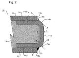
図2は、構造サンドイッチ板部材10における接続部材14の位置をより詳細に示す。図示するように、接続部材14は、コーナー14b、14cに対する接線A−A、B−Bが、面板11、12の端部11a、12aを通るように突出する。これにより、面板を溶接部が接合するためにコーナー部分14b、14cが溶接準備部を形成する一方で、十分な溶接部を形成するように、隣接する板部材の面板間で十分な空間が残ることが確実にされる。コーナー部分14b、14cの曲率半径rは、接続部材14が圧延される金属板の厚さtの二倍に等しいことが好ましい。厚さtは、板が用いられる適用法に依存するが、一般的に、造船適用法に対する例えば、5mmまたは6mmといった面板11、12の厚さに匹敵する。
FIG. 2 shows in more detail the position of the connecting
接続部材は、十分な強度で面板に接続される場合、接合の領域における板部材の強度に著しく寄与する。これは、面板間の溶接部からの熱がエラストマーコア部に損傷を与える場合でも、板部材が十分な強度を有することを確実にする。この場合、接続部材はワンパスシール溶接部33を用いて面板に溶接され得る。
When the connecting member is connected to the face plate with sufficient strength, it significantly contributes to the strength of the plate member in the joining region. This ensures that the plate member has sufficient strength even when heat from the weld between the face plates damages the elastomer core. In this case, the connecting member can be welded to the face plate using the one-
接続部分14、24は、最終的な構造において、構造サンドイッチ板部材間の荷重を負う必要がない場合、コア部13、23によってそれぞれの板部材に結合され得る。従って、板部材が形成されると、コネクタ14、24は、パネルの構成方法に適切な任意の簡単且つ便利な方法によって定位置で保持され得る。例えば、板部材が鋳型で形成される場合、面板により支えられる鋳型の締め付け力が、接続部材を定位置で保持するに十分である。あるいは、軽量な接着剤、または、数個のスポット溶接で十分である。板部材が、コア部の注入のための空洞を画定するように、鋳型を用いることなく面板を用いて形成される場合、接続部材は、造船用接着剤または軽量溶接を用いて定位置で保持される。
The connecting
板部材の製造は、その場所で、あるいは、工場状態によって離れた場所で実施され、設置場所に完成したパネルが運搬される。 The manufacture of the plate member is performed at the place or at a place separated by the factory state, and the completed panel is transported to the installation place.
上述の説明が制限的でなく、添付の特許請求の範囲で定められる本発明の範囲内にある他の変更態様および変形例も可能であることが、理解されるであろう。 It will be understood that the above description is not restrictive and that other modifications and variations are possible which are within the scope of the invention as defined by the appended claims.
Claims (11)
接合されるべき構造サンドイッチ板部材の縁に、チャネル形状の接続部材を設ける工程であって、接続部材が間に嵌合され、それぞれの構造サンドイッチ板部材の外板の端部を越えて突出する、接着部材を設ける工程と、
接合されるべき縁が衝合、または、略衝合されるように構造サンドイッチ板部材を配置する工程と、
二枚の構造サンドイッチ板部材の外板間に溶接部を形成する工程と、
を備える、方法。 Each of the two structural sandwich plate members comprises two skins and a core of plastic or polymer material that is coupled to the skin with sufficient strength to transmit a shear force therebetween. A method of connecting two structural sandwich plate members,
A step of providing a channel-shaped connecting member on the edge of the structural sandwich plate member to be joined, the connecting member being fitted therebetween and protruding beyond the end of the outer plate of each structural sandwich plate member Providing an adhesive member;
Placing the structural sandwich plate member such that the edges to be joined are abutted or substantially abutted;
Forming a weld between the outer plates of the two structural sandwich plate members;
A method comprising:
二枚の外板と、
部材の構造強度に実質的に寄与するよう十分な強度で外板に結合される小型のプラスチックまたはポリマー材料のコア部と、
間に嵌合され、前記外板の端部を越えて突出する少なくとも一つの接続部材であって、同様の構造サンドイッチ板部材における同様の接続部材に溶接されるよう適合される表面を有する接続部材と、
を備える、構造サンドイッチ板部材。 A structural sandwich plate member,
Two skins,
A small plastic or polymer material core that is joined to the skin with sufficient strength to substantially contribute to the structural strength of the member;
At least one connecting member fitted between and projecting beyond the end of the outer plate, the connecting member having a surface adapted to be welded to a similar connecting member in a similar structural sandwich plate member When,
A structural sandwich plate member comprising:
Applications Claiming Priority (2)
| Application Number | Priority Date | Filing Date | Title |
|---|---|---|---|
| GB0306198A GB2399539B (en) | 2003-03-18 | 2003-03-18 | Method for connecting structural sandwich plate members |
| PCT/GB2004/000704 WO2004082886A1 (en) | 2003-03-18 | 2004-02-23 | Method for connecting by welding structural sandwich plate members with channel-shaped connecting members |
Publications (2)
| Publication Number | Publication Date |
|---|---|
| JP2006521210A true JP2006521210A (en) | 2006-09-21 |
| JP2006521210A5 JP2006521210A5 (en) | 2007-04-05 |
Family
ID=9955008
Family Applications (1)
| Application Number | Title | Priority Date | Filing Date |
|---|---|---|---|
| JP2006505891A Pending JP2006521210A (en) | 2003-03-18 | 2004-02-23 | Method for connecting channel-shaped connecting member and structural sandwich plate member by welding |
Country Status (12)
| Country | Link |
|---|---|
| US (1) | US20060165480A1 (en) |
| EP (1) | EP1603703B1 (en) |
| JP (1) | JP2006521210A (en) |
| KR (1) | KR20050111777A (en) |
| CN (1) | CN100448595C (en) |
| AT (1) | ATE375223T1 (en) |
| DE (1) | DE602004009415T2 (en) |
| DK (1) | DK1603703T3 (en) |
| ES (1) | ES2294472T3 (en) |
| GB (1) | GB2399539B (en) |
| PT (1) | PT1603703E (en) |
| WO (1) | WO2004082886A1 (en) |
Cited By (1)
| Publication number | Priority date | Publication date | Assignee | Title |
|---|---|---|---|---|
| JP2011011215A (en) * | 2009-06-30 | 2011-01-20 | Kobe Steel Ltd | Welding method of metallic sheet member |
Families Citing this family (17)
| Publication number | Priority date | Publication date | Assignee | Title |
|---|---|---|---|---|
| GB2421471B (en) * | 2004-12-23 | 2009-12-23 | Intelligent Engineering | Improved structural sandwich plate members |
| US20060283140A1 (en) * | 2005-06-03 | 2006-12-21 | Intelligent Engineering (Bahamas) Limited | Wooden decks |
| NL1032255C1 (en) * | 2006-07-31 | 2008-02-01 | Ro Groep Holding B V | Shelter, a method for providing a bulletproof and / or anti-flaky layer with a wall or a panel and a shelter, vehicle, vessel or aircraft, provided with a wall or a panel, manufactured according to this method. |
| US8733033B2 (en) | 2008-06-27 | 2014-05-27 | Millport Associates, SA | Sandwich panel ground anchor and ground preparation for sandwich panel structures |
| US8782991B2 (en) | 2008-07-10 | 2014-07-22 | Millport Associates S.A. | Building roof structure having a round corner |
| ATE508865T1 (en) * | 2008-07-30 | 2011-05-15 | 3A Technology & Man Ag | FOAMED PLASTIC BOARD |
| GB2465568A (en) * | 2008-11-19 | 2010-05-26 | Intelligent Engineering | A prefabricated floor panel |
| US8992709B2 (en) * | 2009-12-04 | 2015-03-31 | The Boeing Company | Sandwich structure having arrestment feature and method of making the same |
| KR20130010243A (en) * | 2011-07-18 | 2013-01-28 | 대우조선해양 주식회사 | Connection sturucture for stuructural sandwich plate system |
| WO2013147035A1 (en) * | 2012-03-28 | 2013-10-03 | 新日鐵住金株式会社 | Tailored blank for hot stamping, hot-stamped member, and processes for producing same |
| SA113340432B1 (en) | 2012-04-14 | 2015-09-29 | كيري الن هايز | A method of manufacturing a composite building element and system therefore |
| US8875475B2 (en) | 2013-03-14 | 2014-11-04 | Millport Associates S.A. | Multiple panel beams and methods |
| GB201308646D0 (en) * | 2013-05-14 | 2013-06-26 | Keystone Lintels Ltd | A Reinforced Building Panel |
| US10683158B2 (en) * | 2017-01-26 | 2020-06-16 | Pelican Biothermal, Llc | Protectively framed and covered thermal insulation panel |
| EP3652388B1 (en) * | 2017-07-10 | 2021-08-25 | Amovido A/S | Building construction system |
| CN111295327B (en) * | 2017-09-12 | 2023-03-21 | 丁泰瑛 | Thermal insulation structural material and low-temperature and very-low-temperature liquefied gas carrier using same |
| CN111408904B (en) * | 2020-04-02 | 2021-10-01 | 宁夏大学 | Method for preparing sandwich plate with high efficiency and high quality by electric arc and sandwich plate |
Citations (1)
| Publication number | Priority date | Publication date | Assignee | Title |
|---|---|---|---|---|
| WO2002068186A1 (en) * | 2001-02-27 | 2002-09-06 | Intelligent Engineering (Bahamas) Limited | Improved structural sandwich plate members |
Family Cites Families (15)
| Publication number | Priority date | Publication date | Assignee | Title |
|---|---|---|---|---|
| US1907051A (en) * | 1931-05-18 | 1933-05-02 | Wallace V Emery | Metallic welding electrode |
| US3235040A (en) * | 1963-05-03 | 1966-02-15 | Dow Chemical Co | Sandwich panel structure with edge trim |
| CH490588A (en) * | 1968-12-04 | 1970-05-15 | Sonderegger Emil | Prefabricated element |
| DE2630479C2 (en) * | 1976-07-07 | 1982-10-14 | Lampertz, Horst, 5241 Wallmenroth | Insulating element for fireproof room cladding |
| ES2008680B3 (en) * | 1985-11-29 | 1989-08-01 | Atochem | METALOPLASTIC COMPOSITE CONTAINERS ASSEMBLED BY WELDING AND MANUFACTURING SUPPLEMENT. |
| US5580636A (en) * | 1993-09-17 | 1996-12-03 | Alusutsse-Lonza Services Ltd. | Welded composite panels |
| SE505467C2 (en) * | 1995-11-07 | 1997-09-01 | Glasis Holding Ab | Panel elements |
| US6050208A (en) * | 1996-11-13 | 2000-04-18 | Fern Investments Limited | Composite structural laminate |
| US5778813A (en) * | 1996-11-13 | 1998-07-14 | Fern Investments Limited | Composite steel structural plastic sandwich plate systems |
| US6706406B1 (en) * | 1996-11-13 | 2004-03-16 | Fern Investments Limited | Composite steel structural plastic sandwich plate systems |
| DE19727660A1 (en) * | 1997-06-30 | 1999-01-07 | Teskom Schallschutz Gmbh | Flat structure especially sound or peep-proof modular wall |
| DE19961696C1 (en) * | 1999-12-21 | 2001-04-19 | Keiper Gmbh & Co | Connection method for automobule seat components has projections of one component welded within corresponding reception bores provided by second component |
| GB2380970B (en) * | 2001-10-15 | 2005-02-16 | Intelligent Engineering | Connector for structural sandwich plate members |
| GB2384461B (en) * | 2002-01-28 | 2005-03-16 | Intelligent Engineering | Improved structural sandwich plate members |
| GB2413308B (en) * | 2002-05-31 | 2006-03-15 | Intelligent Engineering | Double hull formed from elastomer laminate plating |
-
2003
- 2003-03-18 GB GB0306198A patent/GB2399539B/en not_active Expired - Lifetime
-
2004
- 2004-02-23 DK DK04713589T patent/DK1603703T3/en active
- 2004-02-23 JP JP2006505891A patent/JP2006521210A/en active Pending
- 2004-02-23 DE DE602004009415T patent/DE602004009415T2/en not_active Expired - Lifetime
- 2004-02-23 KR KR1020057017444A patent/KR20050111777A/en not_active Application Discontinuation
- 2004-02-23 WO PCT/GB2004/000704 patent/WO2004082886A1/en active IP Right Grant
- 2004-02-23 EP EP04713589A patent/EP1603703B1/en not_active Expired - Lifetime
- 2004-02-23 ES ES04713589T patent/ES2294472T3/en not_active Expired - Lifetime
- 2004-02-23 US US10/549,009 patent/US20060165480A1/en not_active Abandoned
- 2004-02-23 AT AT04713589T patent/ATE375223T1/en active
- 2004-02-23 PT PT04713589T patent/PT1603703E/en unknown
- 2004-02-23 CN CNB2004800073079A patent/CN100448595C/en not_active Expired - Fee Related
Patent Citations (1)
| Publication number | Priority date | Publication date | Assignee | Title |
|---|---|---|---|---|
| WO2002068186A1 (en) * | 2001-02-27 | 2002-09-06 | Intelligent Engineering (Bahamas) Limited | Improved structural sandwich plate members |
Cited By (1)
| Publication number | Priority date | Publication date | Assignee | Title |
|---|---|---|---|---|
| JP2011011215A (en) * | 2009-06-30 | 2011-01-20 | Kobe Steel Ltd | Welding method of metallic sheet member |
Also Published As
| Publication number | Publication date |
|---|---|
| CN1761550A (en) | 2006-04-19 |
| GB2399539A (en) | 2004-09-22 |
| DE602004009415D1 (en) | 2007-11-22 |
| US20060165480A1 (en) | 2006-07-27 |
| GB0306198D0 (en) | 2003-04-23 |
| DE602004009415T2 (en) | 2008-07-24 |
| KR20050111777A (en) | 2005-11-28 |
| ES2294472T3 (en) | 2008-04-01 |
| EP1603703A1 (en) | 2005-12-14 |
| DK1603703T3 (en) | 2008-02-11 |
| GB2399539B (en) | 2005-09-07 |
| PT1603703E (en) | 2007-12-18 |
| CN100448595C (en) | 2009-01-07 |
| WO2004082886A1 (en) | 2004-09-30 |
| ATE375223T1 (en) | 2007-10-15 |
| EP1603703B1 (en) | 2007-10-10 |
Similar Documents
| Publication | Publication Date | Title |
|---|---|---|
| JP2006521210A (en) | Method for connecting channel-shaped connecting member and structural sandwich plate member by welding | |
| US20040105960A1 (en) | Structural sandwich members | |
| JP4712280B2 (en) | Improved structural sandwich plate member | |
| US6478367B2 (en) | Vehicle body reinforcement structure | |
| US8973332B2 (en) | Framework connecting device of prefabricated building structure | |
| US9475252B2 (en) | System and method for reducing core of a metallic honeycomb panel structure | |
| KR102108621B1 (en) | Concrete structure construction frame using insulation instead of formwork and method of installing the same | |
| JP2001310759A (en) | Implement and method for reinforcing hollow structure | |
| US11794815B2 (en) | Reinforced interlocking frame system and components therefor | |
| JP2005527411A (en) | Improved structural sandwich plate member | |
| EP1379379B1 (en) | Improved structural sandwich members | |
| US4373311A (en) | Integral housing body | |
| JPH07205350A (en) | Rigid structure and shelf board with the rigid structure incorporated | |
| KR101745457B1 (en) | Recycle lumber furniture panel capable of weight lighting and prevention of bending and manufactureing method therefor | |
| JP2002531731A (en) | Wooden truss structure system for frames, bridges, floors, etc. | |
| KR101280479B1 (en) | Panel assembly | |
| KR101085309B1 (en) | Core parts for panel and sandwich panel using the same | |
| JP7278587B2 (en) | Bracing hardware and joint structure of wooden building using it | |
| KR101447513B1 (en) | Structure for connecting steel plate structure and sandwich plate system | |
| JP2001048292A (en) | Sandwich panel structure for van body having recessed groove | |
| JPH05163894A (en) | Synthetic segment | |
| JP4227583B2 (en) | Columnar open cross-section member constructed by assembling groove-shaped metal members | |
| JPH02155638A (en) | Composite structural material | |
| KR20220152730A (en) | Manufacturing method for roof panel, and roof panel manufactured by the same | |
| JPH10280651A (en) | Floor panel and manufacture thereof |
Legal Events
| Date | Code | Title | Description |
|---|---|---|---|
| A521 | Request for written amendment filed |
Free format text: JAPANESE INTERMEDIATE CODE: A523 Effective date: 20070214 |
|
| A621 | Written request for application examination |
Free format text: JAPANESE INTERMEDIATE CODE: A621 Effective date: 20070214 |
|
| A131 | Notification of reasons for refusal |
Free format text: JAPANESE INTERMEDIATE CODE: A131 Effective date: 20091006 |
|
| A601 | Written request for extension of time |
Free format text: JAPANESE INTERMEDIATE CODE: A601 Effective date: 20091224 |
|
| A602 | Written permission of extension of time |
Free format text: JAPANESE INTERMEDIATE CODE: A602 Effective date: 20100106 |
|
| A521 | Request for written amendment filed |
Free format text: JAPANESE INTERMEDIATE CODE: A523 Effective date: 20100401 |
|
| A02 | Decision of refusal |
Free format text: JAPANESE INTERMEDIATE CODE: A02 Effective date: 20101214 |