JP2006517293A - Imaging system - Google Patents
Imaging system Download PDFInfo
- Publication number
- JP2006517293A JP2006517293A JP2006502200A JP2006502200A JP2006517293A JP 2006517293 A JP2006517293 A JP 2006517293A JP 2006502200 A JP2006502200 A JP 2006502200A JP 2006502200 A JP2006502200 A JP 2006502200A JP 2006517293 A JP2006517293 A JP 2006517293A
- Authority
- JP
- Japan
- Prior art keywords
- focusing
- optical
- beam splitter
- common
- path
- Prior art date
- Legal status (The legal status is an assumption and is not a legal conclusion. Google has not performed a legal analysis and makes no representation as to the accuracy of the status listed.)
- Pending
Links
- 238000003384 imaging method Methods 0.000 title claims abstract description 11
- 230000003287 optical effect Effects 0.000 claims abstract description 54
- 230000010287 polarization Effects 0.000 claims description 26
- 210000001747 pupil Anatomy 0.000 claims description 12
- 230000005540 biological transmission Effects 0.000 claims description 6
- 230000002999 depolarising effect Effects 0.000 claims description 3
- 230000001934 delay Effects 0.000 abstract 1
- 238000005259 measurement Methods 0.000 description 10
- 238000000034 method Methods 0.000 description 6
- 230000005855 radiation Effects 0.000 description 5
- 229910021532 Calcite Inorganic materials 0.000 description 4
- 239000006185 dispersion Substances 0.000 description 4
- 230000008859 change Effects 0.000 description 3
- 230000000295 complement effect Effects 0.000 description 3
- 230000000694 effects Effects 0.000 description 3
- 230000004048 modification Effects 0.000 description 3
- 238000012986 modification Methods 0.000 description 3
- 210000000887 face Anatomy 0.000 description 2
- BQCADISMDOOEFD-UHFFFAOYSA-N Silver Chemical compound [Ag] BQCADISMDOOEFD-UHFFFAOYSA-N 0.000 description 1
- 239000002131 composite material Substances 0.000 description 1
- 230000007123 defense Effects 0.000 description 1
- 239000010453 quartz Substances 0.000 description 1
- 230000004044 response Effects 0.000 description 1
- VYPSYNLAJGMNEJ-UHFFFAOYSA-N silicon dioxide Inorganic materials O=[Si]=O VYPSYNLAJGMNEJ-UHFFFAOYSA-N 0.000 description 1
- 229910052709 silver Inorganic materials 0.000 description 1
- 239000004332 silver Substances 0.000 description 1
Images


Classifications
-
- G—PHYSICS
- G01—MEASURING; TESTING
- G01J—MEASUREMENT OF INTENSITY, VELOCITY, SPECTRAL CONTENT, POLARISATION, PHASE OR PULSE CHARACTERISTICS OF INFRARED, VISIBLE OR ULTRAVIOLET LIGHT; COLORIMETRY; RADIATION PYROMETRY
- G01J9/00—Measuring optical phase difference; Determining degree of coherence; Measuring optical wavelength
- G01J2009/002—Wavefront phase distribution
Abstract
光学装置であって、その光学装置は、(CCDカメラのセンサーのような)共通面(13)の個々に分離された第一と第二の領域において、第一と第二の同軸上に隔置された対物面の焦点を同時に合わせるための装置であり、かつ、前記第一と第二の光学パス(3、4)に沿って前記第一と第二の像領域へ伝達するための共通パス(2)に沿った前記対物面からの光を受光するための無回折ビームスプリッタ手段、および、前記第一と第二の対物面を前記第一と第二の領域で焦点を合わせるための反射または透過する合焦手段(8)からなる装置である。(異なる物理的な長さ、かつ/または、異なる光遅延を使用することで)異なる長さのパス(3、4)を有すること、かつ/または、二つのパスにおいて異なるフォーカッシングパワー(focussing power)を有することで、この対物面を違えることができる。カメラへの追加物として、異なって湾曲した長焦点距離のミラーがメインのカメラレンズを変更する。二つの像を分離するために偏光光学系を使用することが考えられる。当該装置は3−Dイメージングや波面解析に使用することも考えられる。An optical device, the optical device being separated on a first and second coaxial axis in individually separated first and second regions of a common plane (13) (such as a sensor of a CCD camera). A device for simultaneously focusing the placed object planes and for transmitting to the first and second image areas along the first and second optical paths (3, 4) Non-diffracting beam splitter means for receiving light from the object plane along path (2), and for focusing the first and second object planes in the first and second regions It is an apparatus comprising focusing means (8) that reflects or transmits. Having different length paths (3, 4) (by using different physical lengths and / or different optical delays) and / or different focusing powers in the two paths ), The object plane can be changed. As an addition to the camera, a differently curved long focal length mirror changes the main camera lens. It is conceivable to use a polarizing optical system to separate the two images. The apparatus may be used for 3-D imaging and wavefront analysis.
Description
我々の同時係属中の出願番号GB0205240.5の英国特許出願は、瞳面に到来する放射波面の局所的な形状(または局所的な位相の分布)に関連するデータのリアルタイムな判定のための測定装置/方法に関するものである。記載されている構成は異なるタイプの放射に使用し得るが、一つの特有の使用は光についての使用であり、特に可視光または赤外線である。特に記載したように、実施例は瞳面のどちらか一方の脇に等しく隔置され、密接に隣り合った測定面での放射分布の強さについての比較を必要とする。 Our co-pending GB Patent Application No. GB0205240.5 is a measurement for the real-time determination of data related to the local shape (or local phase distribution) of the radiating wavefront arriving at the pupil plane It relates to an apparatus / method. Although the described arrangement can be used for different types of radiation, one particular use is for light, in particular visible or infrared. As described in particular, the examples are equally spaced on either side of the pupil plane and require a comparison of the intensity of the radiation distribution on closely adjacent measurement planes.
当該出願中に記載されているように、この目的のため(またはその他の光学的な測定のため)に、単に一対のレンズとビームスプリッタを使用して、二つの対物面の個々の焦点を合わせた像をイメージセンサが配置された異なる像面に向けることも可能である。しかし、光学構成要素やセンサーの正確な位置合わせのメンテナンスおよび二つの個々のセンサーを同時に操作しなければならないという潜在的な不利益を有している。 For this purpose (or other optical measurements) as described in that application, simply use a pair of lenses and a beam splitter to focus the two object planes individually. It is also possible to direct the image to different image planes on which image sensors are arranged. However, it has the potential disadvantage of maintaining accurate alignment of optical components and sensors and having to operate two individual sensors simultaneously.
したがって、特により好ましく、我々の同時係属出願に開示されている様に、我々の先行する同時係属中の出願番号WO99/46768の国際特許出願(出願人は国防大臣(Secretary of State for Defence)として公開)に説明されているタイプの歪んだ回折格子、または、コンピュータによるホログラムを使用することで、前述の強度分布比較は達成される。そのようにすると、例えば格子からの正または負の1次回折を使用することで、例えばセンサーアレーのような共通センサー面上で横方向に移動した像として、二つの測定面は同時に焦点を合わせることができる。0次回折光もまた格子によって伝達することができ、また、単一のセンサーかセンサーアレーからなる同一センサー面かまたは異なるセンサー面のいずれかの上に、例えば(入射瞳と対立するものとして)遠隔の対象物の像を、同時に提供するために使用することもできる。 Thus, it is particularly more preferred and as disclosed in our co-pending application, our earlier co-pending application number WO 99/46768 as an international patent application (as the applicant of the Secretary of State for Defense) The aforementioned intensity distribution comparison is achieved by using a distorted diffraction grating of the type described in (publication) or a computer generated hologram. In that way, the two measurement planes are simultaneously focused, for example as an image moved laterally on a common sensor plane such as a sensor array, using positive or negative first order diffraction from the grating, for example. be able to. Zero-order diffracted light can also be transmitted by the grating and can be remote, for example (as opposed to the entrance pupil), either on the same sensor surface consisting of a single sensor or sensor array, or on a different sensor surface. Can be used to simultaneously provide images of the objects.
格子かホログラムを採用することに伴う不利益がないというわけではない。特に、そのような素子は高い分散性を有する。したがって、信用できる測定を提供するためには、理想的には、入力を単色または狭帯域放射として、その格子を使用すべきことがよく知られている。 It is not without the disadvantages of adopting a grating or hologram. In particular, such devices have high dispersibility. Therefore, to provide a reliable measurement, it is well known that ideally the grating should be used with the input as monochromatic or narrowband radiation.
測定される入力放射の帯域幅を制限するもう一つの方法は、常に可能であるわけではない。例えば、入射瞳を提供する可視光光学カメラの焦点を制御するために、可視対象物の範囲測定を提供するための測定システムの出力を使用することが望まれるであろう(すなわちオートフォーカスシステム)。上述したが、0次回折光はこの目的で使用することができる。格子または/かつ拡張された像の測定用の構成の応答によって示された分散は、オートフォーカスファンクションに非常に悪い信頼性を導くかもしれない。 Another way to limit the bandwidth of the measured input radiation is not always possible. For example, it may be desirable to use the output of a measurement system to provide a range measurement of a visible object to control the focus of a visible light optical camera that provides an entrance pupil (ie, an autofocus system). . As described above, zero-order diffracted light can be used for this purpose. The dispersion exhibited by the response of the grating or / and the expanded image measurement configuration may lead to very poor reliability for the autofocus function.
したがって、分散の問題を回避し削減するような方法で、一つの共通面上の異なった領域に、軸上を移動させた二つの面から導出された像を得ることが好ましい。 Therefore, it is preferable to obtain images derived from two planes moved on an axis in different regions on one common plane in a way that avoids and reduces dispersion problems.
第一の形態では、本発明は、共通の像面の個々に分離している第一と第二の領域で、第一と第二の同軸方向に隔置された対物面の焦点を同時に合わせるための光学装置を提供する。当該装置は、無回折ビームスプリッタ手段であって、前記第一と第二の像領域へ個々の第一と第二の光路に沿って伝達するための共通パスに沿って前記対物面から到来する光を受光するための手段と、前記第一と第二の対物面を前記第一と第二の領域で焦点を合わせるように用意された合焦手段とからなる。 In a first form, the present invention simultaneously focuses first and second coaxially spaced object surfaces in first and second regions of a common image plane that are individually separated. An optical device is provided. The apparatus is a diffractive beam splitter means, coming from the object plane along a common path for transmission along the respective first and second optical paths to the first and second image regions Means for receiving light and focusing means prepared to focus the first and second object planes in the first and second regions.
我々の先行出願における歪んだ格子との混乱を避けるために、ビームスプリッタは「無回折」と称することとする。一般的に、このビームスプリッタは、従来型のスプリッタであって、一部透過し、一部反射する表面を使用したものが考えられる。しかし、もう一つの方法としては、偏光スプリッタが考えられる。偏光スプリッタにおいては、偏光に従って、二つの偏光に与えられる異なる反射指数によって、光が個々の光路に沿って方向付けられる(これらは一般に直線偏光であるが、円偏光やその他のタイプの偏光となり得る。一般的にこれらの二つの偏光タイプは相補的となるであろう。)。 In order to avoid confusion with the distorted grating in our prior application, the beam splitter will be referred to as “diffractive”. In general, this beam splitter is a conventional splitter that uses a partially transmitting and partially reflecting surface. However, a polarization splitter can be considered as another method. In a polarization splitter, light is directed along individual optical paths according to polarization, with different reflection indices applied to the two polarizations (these are generally linearly polarized, but can be circularly polarized or other types of polarization) (In general, these two polarization types will be complementary.)
本発明のいくつかの実施例では、ビームスプリッタ手段および合焦手段は一つの光学素子によって可能とされ、例えば複屈折レンズ構造が挙げられる。しかし、これらの機能は分離されている方が、より一般的である。 In some embodiments of the present invention, the beam splitter means and the focusing means are enabled by a single optical element, for example a birefringent lens structure. However, it is more common for these functions to be separated.
ビームスプリッタ手段としては、ほぼ平行な前記第一と第二のパスを与えるタイプのビームスプリッタが挙げられる。ビームスプリッタ手段が、はっきりと角度を持って分離された第一と第二の出力パスを与えるタイプのビームスプリッタからなる場合には、例えばそれらのパスが共通面に到達する際に、それらのパスをほぼ平行にするための一つかそれ以上の反射面のような手段を用意する方法もまた考えられる。 Examples of the beam splitter means include a beam splitter of the type that provides the first and second paths which are substantially parallel. If the beam splitter means consists of a beam splitter of the type that gives a first and a second output path that are clearly separated by an angle, for example when these paths reach a common plane, It is also conceivable to provide means such as one or more reflective surfaces to make the two substantially parallel.
その光はビームスプリッタを一回または複数回横切る。さらなる詳細を述べるための二つの実施例では、第一と第二のパスをスプリッタへ戻し、そこから、共通像面中の第一と第二の像領域方向へ方向付けを行うために、個々の反射面が提供される。 The light traverses the beam splitter one or more times. In two embodiments to give further details, the first and second paths are returned to the splitter, from which to direct the first and second image areas in the common image plane, respectively. A reflective surface is provided.
この合焦手段は一つかそれ以上の屈折素子、一つかそれ以上の反射焦点合わせ素子、または屈折素子と反射焦点合わせ素子の組み合わせからなることも考えられる。 It is also conceivable that this focusing means consists of one or more refractive elements, one or more reflective focusing elements, or a combination of refractive and reflective focusing elements.
光学装置の第一の形態では、共通面と合焦手段との間にビームスプリッタが設置される。第二の形態では、スプリッタと共通面の間に合焦手段が設置される。さらに、合焦手段は第一と第二のパスに共通の素子(例えば、インターセプト)、および/または、第一と第二のパス用の別個の素子からなることも考えられる。第三の形態では、合焦手段は複数の焦点合わせ素子からなり、少なくとも一つの素子がビームスプリッタの前方に設置され、少なくとも一つの素子がその後ろに設置される。 In the first embodiment of the optical device, a beam splitter is installed between the common surface and the focusing means. In the second embodiment, focusing means is installed between the splitter and the common surface. Furthermore, it is conceivable that the focusing means consists of elements common to the first and second paths (for example, intercepts) and / or separate elements for the first and second paths. In the third embodiment, the focusing means is composed of a plurality of focusing elements, at least one element is installed in front of the beam splitter, and at least one element is installed behind it.
光学装置の第一の形態では、合焦手段は共通パス中に設置される。共通像面上で同軸上に隔置された第一と第二の対物面の焦点を合わせるために、第一と第二のパスは異なる光路長である必要がある。これはパス長を物理的に違うものとすることによって実現され得るし、少なくとも一つのパス中に光学遅延素子を挿入することでも実現され得るし、または、これらの両方の技術の組合せによっても実現され得る。 In the first form of the optical device, the focusing means is installed in the common path. In order to focus the first and second objective surfaces that are coaxially spaced on the common image plane, the first and second paths need to have different optical path lengths. This can be achieved by physically different path lengths, by inserting an optical delay element in at least one path, or by a combination of both these techniques. Can be done.
第一と第二のパス長の物理的な差は、それ自体が知られているいかなる方法、例えば、第一と第二のパスのうち少なくとも一つの中で、少なくとも一つの反射器の使用することでパス長を長くする方法によっても得ることができる。一つの実施例では、ビームスプリッタおよび/または共通面から異なる間隔で、第一と第二の両方のパス中に反射器が挿入される。例えば、第一と第二のパス中に好ましく配置された反射面は、ビームスプリッタに光を戻し、そこから共通像面へ光を入力させ、その表面はビームスプリッタから不均等に隔置される。 The physical difference between the first and second path lengths can be determined by any method known per se, for example using at least one reflector in at least one of the first and second paths. Thus, it can also be obtained by a method of increasing the path length. In one embodiment, reflectors are inserted in both the first and second paths at different distances from the beam splitter and / or common plane. For example, a reflective surface that is preferably placed in the first and second passes returns light to the beam splitter from which it enters the common image plane, the surface of which is unevenly spaced from the beam splitter. .
光遅延の導入は、第一と第二のパスの少なくとも一つの中で、比較的密度の高い透過型の板の挿入によって達成される。いくつかの本発明の実施例では、後により詳細を述べるような、ウェッジプリズム(Wedge prism)のような一般的な光学素子によって、ビームスプリッタと光遅延手段が提供される。 The introduction of the optical delay is achieved by inserting a relatively dense transmissive plate in at least one of the first and second passes. In some embodiments of the present invention, the beam splitter and optical delay means are provided by a common optical element, such as a wedge prism, as will be described in more detail later.
ビームスプリッタが偏光に敏感に反応し相補的な偏光のような異なる偏光の出力ビームを提供する場合、または、第一と第二のパスが異なる偏光を選択するための手段からなる場合に、異なる光路長を異なる偏光に与えるために比較的密度の高い透過型の板を配置することができる(例えば、二つの出力ビームが直線偏光である場合の複屈折)。必要不可欠な効果のために、合焦手段の後に、または、少なくともその合焦手段の第一番目の焦点合わせ素子の後に、それは配置されるべきである(または、前記第一と第二のそれぞれの中に配置された個々の板)。これは、全体の構成によって決定されるように、共通パスかまたは第一と第二のパスの少なくとも一つの中とすることが考えられる。好ましくは、二つの偏光のパワーを均等化するために、減偏光子が偏光ビームスプリッタか偏光選択手段の前に配置される。 Different if the beam splitter is sensitive to polarization and provides an output beam of different polarization, such as complementary polarization, or if the first and second paths consist of means for selecting different polarizations A relatively dense transmissive plate can be placed to provide different path lengths for different polarizations (eg, birefringence when the two output beams are linearly polarized). For indispensable effects, it should be placed after the focusing means or at least after the first focusing element of the focusing means (or said first and second respectively) Individual plates arranged in the). This can be in a common path or in at least one of the first and second paths, as determined by the overall configuration. Preferably, a depolarizer is placed in front of the polarization beam splitter or polarization selection means in order to equalize the power of the two polarizations.
もう一つの選択的な構成では、スプリッタの一方または反対の側面に配置された複屈折レンズのような一般的な光学素子によって、合焦手段と遅延手段が提供される。そのスプリッタは、先程と同様に偏光に敏感に反応するか、または異なる偏光を選択するための手段を第一および第二のパスの中に備えている。 In another alternative arrangement, the focusing means and the delay means are provided by a common optical element such as a birefringent lens located on one or the opposite side of the splitter. The splitter is sensitive to the polarization as before, or comprises means in the first and second pass for selecting a different polarization.
装置の第二の形態では、合焦手段は第一と第二のパスの両方に適応するのに十分な開口度を有しており、したがって、両方のパスに共通な光学素子からなる。もしこれが焦点合わせのためだけの素子であれば、装置の第一の形態でのように、第一と第二の光路長は異なるように設定される。 In the second form of the device, the focusing means has an aperture sufficient to accommodate both the first and second passes, and thus consists of optical elements common to both passes. If this is an element only for focusing, the first and second optical path lengths are set differently as in the first configuration of the apparatus.
もう一つの方法として、合焦手段は第一と第二のパスのそれぞれで別個の焦点合わせ素子からなることが考えられる。これらの焦点合わせ素子は、それぞれ同じフォーカシングパワー(focussing power)をもっており、この場合、装置の第一の形態のように第一と第二の光路長が異なるように設定され、かつ/または、共通面で両方の対物面の焦点を合わせるために、ビームスプリッタか共通面からのそれらの光学的な間隔は異なるものとなっている。もう一つの方法として、焦点合わせ素子は異なるフォーカッシングパワーを有しており、この場合、それらは共通面とビームスプリッタに対して同じ間隔を持っており、共通面で両方の対物面の焦点合わせを可能とする。それでもなお、第一と第二のパス中でそれらを異なるように配置し、かつ/または、第一と第二の光路長の差をつけることも可能である。唯一の必要条件は、第一と第二の対物面の両方が共通面で焦点合わせができるように配置されることである。 Alternatively, the focusing means can be composed of separate focusing elements in each of the first and second passes. These focusing elements each have the same focusing power, in which case the first and second optical path lengths are set differently as in the first form of the apparatus and / or are common In order to focus both object planes on the surface, their optical spacing from the beam splitter or common surface is different. Alternatively, the focusing elements have different focusing powers, in which case they have the same spacing with respect to the common plane and the beam splitter, so that both object planes are focused on the common plane. Is possible. Nevertheless, it is also possible to arrange them differently in the first and second paths and / or to make a difference between the first and second optical path lengths. The only requirement is that both the first and second object planes be arranged so that they can be focused on a common plane.
ビームスプリッタと共通面の間の焦点合わせ素子が第一と第二のパスに共通であるかどうか、単一のそのような焦点合わせ素子が第一か第二のパスの一つの中で提供されるかどうか、または、分離したそのような焦点合わせの素子が第一と第二のパスについて個々に一つずつで提供されるかどうかに従って、前述と同様な考え方が装置の第三の形態へ適用される。 Whether the focusing element between the beam splitter and the common plane is common to the first and second pass, a single such focusing element is provided in one of the first or second pass. Depending on whether or not separate such focusing elements are provided individually for the first and second pass, the same idea as described above is applied to the third form of the device. Applied.
当該装置は共通面にセンサー面を伴うイメージセンサー手段もまた有しており、それによって、第一と第二の像を受け取り、個々のイメージ信号を提供することができる。好ましくは、このセンサー面は単一のセンサー領域であって、第一と第二の像領域の両方に共通である。 The device also has image sensor means with a sensor surface on a common surface, whereby the first and second images can be received and individual image signals can be provided. Preferably, the sensor surface is a single sensor area and is common to both the first and second image areas.
第二の形態では、本発明は、補助的なレンズを伴い、個々の分離した共通面の第一と第二の領域で、第一と第二の同軸上に隔置された対物面の焦点を同時に合わせるために使用する光学装置を提供する。この装置は、個々の第一と第二の光路に沿った前記第一と第二の像領域のための用途で、前記の対物面から伝達するための共通パスに沿った光を受光するための無回折ビームスプリッタ手段と、前記第一と第二の対物面を前記第一と第二の領域で焦点を合わせる前記補助レンズと協働するために準備された合焦手段からなる。同様に第二の形態に、ビームスプリッタと本発明の第一の形態の合焦手段に関連して上記で設定された考え方を適用することが好ましい。 In a second form, the present invention involves an auxiliary lens and the focal points of the first and second coaxially spaced object planes in the first and second regions of each separate common plane. An optical device is provided for use at the same time. This device is for applications for the first and second image areas along the respective first and second optical paths, for receiving light along a common path for transmission from the object plane. And a focusing means prepared for cooperating with the auxiliary lens for focusing the first and second object planes in the first and second regions. Similarly, it is preferable to apply the idea set above in relation to the beam splitter and the focusing means of the first embodiment of the present invention to the second embodiment.
本発明の第二の形態は、例えば、補助レンズが好ましくはデジタルカメラであるカメラのレンズであり、カメラの像またはセンサー面である共通面を伴う状態で、使用することができる装置を提供する。この例では、補助レンズは光学装置と共通面の間に置かれる。しかし、これはもっとも現実的な配置であろうが、本発明の第二の形態においては、共通面と補助レンズの間での当該装置の使用も可能であり(例えば、大きなカメラのようなイメージング装置の内部へ装置を組み込む)、または補助レンズが、共通の、第一の、または、第一および第二のパスの内部で使用されるように配置される場合ですら使用することが可能である。 The second aspect of the present invention provides an apparatus that can be used with a common surface, for example a camera lens, preferably a digital camera, the auxiliary lens being an image or sensor surface of the camera. . In this example, the auxiliary lens is placed between the optical device and the common surface. However, this may be the most realistic arrangement, but in the second form of the invention, it is also possible to use the device between a common surface and an auxiliary lens (for example an imaging like a large camera). Can be used even if the auxiliary lens is arranged to be used within a common, first, or first and second pass) is there.
本発明の態様のどちらか一方に従った、本装置の一つの特に好ましい形態は、入射瞳を有しており、かつ、第一と第二の対物面は前記入射瞳の隣のどちらか一方に配置される。 One particularly preferred form of the device according to one of the aspects of the invention has an entrance pupil, and the first and second object planes are either next to the entrance pupil. Placed in.
共通面にセンサー面を有しているデジタルカメラかその他の撮像装置によって提供されるイメージ信号は、第一と第二の像を比較するために処理され、前記の入射光における光の波の特徴を決定するために解析される結果が得られる。これをリアルタイムで実行するために都合のよい方法が、我々の同時係属出願であって前述した出願番号GB0205240.5である英国出願の中で説明されている。 An image signal provided by a digital camera or other imaging device having a sensor surface on a common surface is processed to compare the first and second images, and the light wave characteristics in said incident light The result is analyzed to determine A convenient way to do this in real time is described in our co-pending application, previously mentioned application number GB0205240.5, in the UK application.
一つのそういった特性はチップ/チルト(tip/tilt)であり、その場合、可動性のパスを前記入射瞳からの光路中に配置すること、および、チップ/チルトミラーを制御するための測定されたチップ/チルトに応答する手段を採用することが可能である。ミラーを含んだ光路は、第一と第二のパスの一つであるかもしれないしそうでないかもしれない。そして、この制御は、チップ/チルトを最小にするために例えば通常のフォワード制御やフィードバックタイプの制御とすることが考えられる。 One such property is tip / tilt, in which case a movable path is placed in the optical path from the entrance pupil and measured to control the tip / tilt mirror. It is possible to employ means responding to tip / tilt. The optical path including the mirror may or may not be one of the first and second paths. In order to minimize the tip / tilt, this control may be, for example, normal forward control or feedback type control.
他のそういった特性はピンぼけである。前記入射瞳の視野の中で対象物の範囲の測定をそこから導くことができる。その測定されたピンぼけか測定された範囲のいずれかが、入射瞳からのパス中で、制御可能な合焦手段を制御するために採用され、そのパスは第一のパスか第二のパスの一つであるかもしれないしそうでないかもしれない。再び、その制御は、ピンぼけを最小にするために、例えば、通常のフォワード制御またはフィードバックタイプの制御とすることが考えられる。 Another such characteristic is out of focus. A measurement of the range of the object in the field of view of the entrance pupil can be derived therefrom. Either the measured defocus or the measured range is employed to control a controllable focusing means in the path from the entrance pupil, which path is either the first pass or the second pass. It may or may not be one. Again, the control can be, for example, normal forward control or feedback type control to minimize defocus.
より一般的な応用では、測定された特性は、波面を記述する直交する関数の一つかそれ以上の重み係数、例えば、ゼルニケモード(Zernike mode)からなる(本明細書中の最初に述べた我々の同時係属出願を参照)。この係数は本来的に有用であるか(例えば大気の乱れを評価する)、または、空間光変調は前記入射瞳からの光路(第一か第二のパスの一つまたは二つであるかもしれないしそうでないかもしれない)中に配置されかつ測定された係数に応じて制御される。再び、その制御は、係数を最小にするために、例えば、通常のフォワード制御またはフィードバックタイプの制御とすることが考えられる。 In a more general application, the measured characteristic consists of one or more weighting factors of an orthogonal function describing the wavefront, eg, Zernike mode (we mentioned earlier in this document). For more information). This factor is useful in nature (eg assessing atmospheric turbulence) or spatial light modulation may be the optical path from the entrance pupil (one or two of the first or second path) And possibly controlled) depending on the coefficients located and measured. Again, the control can be, for example, normal forward control or feedback type control, in order to minimize the coefficients.
本発明に従った装置は、我々の同時係属の前記国際特許出願、WO99/46768、で記載している一般的なタイプの3−Dイメージングシステムに使用することも考えられる。 The apparatus according to the invention is also conceivable for use in the general type of 3-D imaging system described in our co-pending said international patent application, WO 99/46768.
本発明のその他の特徴と利点は、読者が参考にする添付された特許請求の範囲を考慮すること、および、これに続く図面を伴う本発明の実施例の更なる詳細な説明によって明確になるであろう。 Other features and advantages of the invention will be apparent from consideration of the appended claims for reference by the reader and further detailed description of embodiments of the invention that follows the accompanying drawings. Will.
図1は、共通パス2からの入射光を受光し、第一と第二のパス3、4上で個々に相補的な直交する直線偏光をもってそれを角度のある移動されたビームへ分割するためのウォラストンプリズム(Wollaston prism)1を示している。ビーム3、4の両方は、方解石板6が後に続くレンズ5によって途中でインターセプトされ、そして、CCDカメラ7もしくはその他のデジタルカメラまたはイメージセンサーのようなセンサーの感知面として具体化された共通面上に到達する。 FIG. 1 receives incident light from a common path 2 and splits it into angularly moved beams with orthogonal linear polarizations which are individually complementary on the first and second paths 3, 4. The Wollaston prism 1 is shown. Both beams 3 and 4 are intercepted in the middle by a lens 5 followed by a calcite plate 6 and on a common surface embodied as a sensing surface of a sensor such as a CCD camera 7 or other digital camera or image sensor. To reach.
その二つの複屈折軸がビーム3、4の個々の偏光の方向に平行であるようにするために、方解石板を配置する。そして結果として、方解石6は光学的厚さを一つのビームに与える。その一つの光学的厚さはもう一方のビームに与えられた光学的厚さよりも大きい。したがって、レンズ5からセンサー7上で焦点を合わせられる(同軸の)対物面への距離は二つの偏光ごとに異なる。二つの同軸の焦点を合わせた面の焦点を合わせた像は、プリズム1の動作によってCCDカメラ上に横方向に移動される。 A calcite plate is arranged so that its two birefringence axes are parallel to the directions of the individual polarizations of the beams 3, 4. As a result, the calcite 6 imparts an optical thickness to one beam. That one optical thickness is greater than the optical thickness imparted to the other beam. Thus, the distance from the lens 5 to the (coaxial) object plane focused on the sensor 7 is different for each of the two polarizations. The focused image of the two coaxially focused surfaces is moved laterally onto the CCD camera by the operation of the prism 1.
変更した形では、二つの同軸上の隔置された面を偏光にしたがってセンサー面で焦点を合わせるために、レンズ5とプリズム1を複屈折レンズで置き換えたものが考えられる。センサー上で焦点を合わせた面を横に分離する機能を実行するためにレンズを調整することも可能ではあろうが、この機能は偏光ビームスプリッタ(例えばウォラストンプリズム)のような別個の素子によってなされる方が、さらに好ましい。 In a modified form, the lens 5 and the prism 1 may be replaced with a birefringent lens in order to focus two coaxially spaced surfaces on the sensor surface according to the polarization. While it may be possible to adjust the lens to perform the function of laterally separating the focused surface on the sensor, this function is achieved by a separate element such as a polarizing beam splitter (eg, a Wollaston prism). More preferably, it is done.
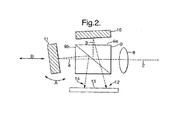
図2は、結像レンズ8が、光を共通パス2からビームスプリッタ9へ、また、第1パス3に沿って反射によって第1ミラーへ、さらに、第2パス4に沿って透過によって第2ミラー11へ伝達することを示している。そこで反射されスプリッタ9によって伝達された光が、CCDカメラの感知面(共通面)13の第1像領域12へ向かうように、ミラー10は固定され光の軸方向へ幾分傾けられる。そこで反射した光が第2像領域14の中の面13に到達するように、ミラー11は同様にして傾けられる。領域13と14の相対位置を制御するために回転方向アジャストメントAがミラー11に適用され、同様にトランジショナル(transitional)アジャストメントBも元の光の軸に沿って第2のパスの第一のパスとの相対的な長さを変更するために適用される。そうすることで、パス2上で軸方向に隔置された第一と第二の対物面の像を面13上で焦点を合わせられるようにする。
FIG. 2 shows that the
図3は図2を変更したものを示しており、その中では、例えばスプリッタのフェイス9a、9bの角度を好ましく調整したり、それらを銀メッキすることで、ビームスプリッタおよび反射器は一つの複合的な構成要素へ統合されている。 FIG. 3 shows a modification of FIG. 2, in which, for example, the angle of the splitter faces 9a, 9b is preferably adjusted, or they are silver plated, so that the beam splitter and reflector are combined into one composite. Is integrated into a typical component.
図4は図2による一般的な基本構想の第二の変更を示したものであり、そこでは、偏光ビームスプリッタ36を採用している。スプリッタ36への入射光は、レンズ8とスプリッタ36の間またはレンズ8の反対側のどちらかに配置された、例えば、水晶/ケイ石ウェッジ(Wedge)減偏光素子のような減偏光板37によって減偏光される。この偏光子は、パワー損失なくスプリッタ36からの同じパワーの二つの偏光が存在することを保証し、二つの偏光の方向に対して45度で入力される偏光子や、第一および第二のパス用のそれぞれの偏光素子を使用するよりも優れている。1/4波長板38、39であって、スプリッタ36からの二つの偏光のそれぞれの中に配置されている1/4波長板は、異なる光路長を導き出し、それによって、二つの同軸対物面のセンサー12上での焦点を隔置することを保証する。図4の構成は、必要であれば、明らかに図2に示すような異なる物理的な光学パスの差を組み込むことも可能であろう。
FIG. 4 shows a second modification of the general basic concept according to FIG. 2, in which a
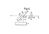
図5は、わずかに傾けられたフェイス25、26を持ったウェッジプリズム24が、結像レンズ27によって伝達された共通パス2からの光のためのビームスプリッタとして作用する構成を示している。レンズ27からの光28の第一の部分は、第一のパス3に沿ってプリズムの第一番目の表面26で反射され、CCDカメラ7の感知面で構成された共通面上で焦点が合わせられる。第二のパスに沿って到来する光の第二番目の部分は、第二番目の表面25で反射され、カメラ7上であって、第一の部分から横方向に移動された場所で焦点が合わせられる。この移動は、一部はプリズムの厚みによって生じるものであるが、ウェッジ型によってもたらされる角距離の効果でもある。残りの光29はこのシステムからは失われるか、またはその他の目的のために伝達される。
FIG. 5 shows a configuration in which a
ビームスプリッタ表面26とCCDカメラの間の第二のパス4は、第一のパス3より長い光路である。したがって、一般的に空気に比べて光学的に密度のより高い媒体のプリズムによって、カメラ7上で二つの横方向に移動された焦点を合わせられた像が、パス2上で同軸上に隔置された対物面にそれぞれ向けられる。
The second path 4 between the
図1と図5では、ビームスプリッタは、出力面で第一と第二のパスを角度を持たせて分岐しており、この角度分岐は共通面まで運ばれる。図2と図4に記載の反射器もまた角度分岐を提供する。したがって、少なくとも一つのパスは面に対しての法線ではなく、関連する像はその全体の領域に渡って完全に焦点があわせられるわけではない。それぞれの場合において、もし必要であれば、少なくとも一つの分離したパスの中で、厳密な平行、共通面上での法線入射および分離した像にわたるしっかりとした焦点を保証するために、チルトされた反射器のようなそれ自体が知られている手段を使用することが考えられる。それでもなお、これらの図の構成において、効果的な測定を可能とするために各像にわたる焦点の十分な度合いを保守しながら、共通面上で空間的に分離された像を提供するのに十分な分岐の総量を提供することも可能である。 In FIG. 1 and FIG. 5, the beam splitter branches the first and second paths at an angle on the output surface, and this angle branch is carried to the common surface. The reflectors described in FIGS. 2 and 4 also provide angular bifurcation. Thus, at least one pass is not normal to the surface and the associated image is not completely focused over its entire area. In each case, if necessary, tilted in at least one separate path to ensure tight parallel, normal incidence on a common plane and a tight focus across the separated image. It is conceivable to use means known per se, such as reflectors. Nonetheless, the configurations in these figures are sufficient to provide spatially separated images on a common plane while maintaining a sufficient degree of focus across each image to allow effective measurement. It is also possible to provide a total amount of branching.
第一と第二のパスが、スプリッタの出力および共通面において並行であるような構成を図6に示す。この構成ではケスタープリズム(Koesters prism)18を採用しており、このプリズムは、共通フェイス21に沿って、二つのプリズム19、20が接合されて形成されている。共通パス2および結像レンズ17からの光は第一のプリズム19に伝達され、ビーム3と4は共通フェイス21で分割され、伝達され、反射される。最終的には横方向に移動された平行ビーム22、23として表出され、CCDカメラ7のセンサー表面上で横方向に隔置され、焦点を合わせられた像を提供する。ビーム23は、プリズム19の底面に固定された(または隣接された)板によってインターセプトされ、それによって、ビーム22のための(第二)パス長に比べて、表面21とビーム23のためのセンサー表面の間のより長い(第一)光路長を提供する。結果として、センサー表面上で横方向に隔置され、焦点を合わせられた像が、パス2上の異なる軸方向に隔置された対物面から導出される。プリズム19のより低い表面を適切に画成することで、同様の効果をえることができる。
A configuration in which the first and second paths are parallel in the output and common plane of the splitter is shown in FIG. In this configuration, a Kester prism 17 is adopted, and this prism is formed by joining two
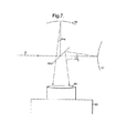
前述の実施例では、光学素子は結像レンズとセンサー面の間に挿入されることが必要であった。しかし、図5の実施例では、標準カメラへの追加物として使用することが可能である。視野からの共通パス2に沿った光は、(プレートスプリッタとして具体化される)無偏光ビームスプリッタ33によって第一パス3に沿って、凸状の反射面32へ伝達され、その後、CCDカメラ35のレンズ34に向けてスプリッタ33によって反射される。はじめにスプリッタ33によって第二パス4に沿って反射された光は、スプリッタを通ってレンズ34へ伝達するために、凹状の反射面31によって反射される。面32と33は、長い焦点距離を有している。これは、カメラ35の(示されていないが)センサー面上で個々の焦点を合わせられた像を提供するために効果的にカメラのレンズの焦点距離を変更することを目的としている。そして、センサー面の(接触または隔置されている)横方向に移動された領域で分離して二つの像を形成するために、それらの軸は設定されている。
In the above embodiment, the optical element has to be inserted between the imaging lens and the sensor surface. However, the embodiment of FIG. 5 can be used as an addition to a standard camera. The light along the common path 2 from the field of view is transmitted along the first path 3 to the convex reflecting
図7における反射面31、32の使用は、レンズを使用した場合に比べてシステム中の分散量を減少させる。図1から4の構成のいかなる(主な)焦点を合わせる手段も分散を減少させる反射手段によって置換することも可能であろう。また、通常、追加物としての追加要素を提供するということと反するが、図7に記載のカメラは、そのレンズを適切に配置された反射器によって置換することもまた可能である。
The use of the reflecting
CCDイメージセンサーが主に述べられたが、もちろんデジタルイメージングシステムやセンサーのいかなるその他の知られた方法によって、または、写真用フィルムのような像様放射記録媒体によって構成されることも可能である。 Although a CCD image sensor has been mainly described, it can of course be constituted by any other known method of a digital imaging system or sensor, or by an image-like radiation recording medium such as a photographic film.
Claims (26)
その装置が前記対物面から個々の第一と第二の光路に沿って前記第一と第二の像領域に伝達するための共通パスに沿って到来する光を受光するための無回折ビームスプリッタ手段と、
前記第一と第二の対物面を前記第一と第二の領域で焦点が合うように配置された合焦手段と、
からなることを特徴とする装置。 An optical device for simultaneously focusing the first and second objective surfaces, which are coaxially spaced apart, in a first and second separately separated areas of a common image plane,
Non-diffractive beam splitter for receiving light coming along a common path from the object plane along the respective first and second optical paths to the first and second image areas. Means,
Focusing means arranged so that the first and second object planes are in focus in the first and second regions;
A device characterized by comprising:
更に、感光面を伴うイメージセンサー手段からなり、その手段が、前記共通焦点面の中にありセンサー面を伴っており、前記焦点を合わせた像を受け取り、かつ、個々のイメージ信号を提供するための手段であることを特徴とする装置。 The apparatus of claim 1, comprising:
Further comprising image sensor means with a photosensitive surface, the means being in the common focal plane and with the sensor surface for receiving the focused image and providing individual image signals An apparatus characterized by the above.
前記補助レンズと共に前記第一と第二の対物面を前記第一と第二の領域で焦点が合うように配置された合焦手段と、
からなることを特徴とする装置。 An optical device used in conjunction with an auxiliary lens to simultaneously focus the first and second objective surfaces, which are separated coaxially, in first and second separate areas of a common image plane. To receive light arriving along a common path for transmission, which the apparatus uses for the first and second image areas along the respective first and second optical paths from the object plane. Non-diffracting beam splitter means,
Focusing means arranged so that the first and second objective surfaces together with the auxiliary lens are in focus in the first and second regions;
A device characterized by comprising:
Applications Claiming Priority (2)
| Application Number | Priority Date | Filing Date | Title |
|---|---|---|---|
| GBGB0301923.9A GB0301923D0 (en) | 2003-01-28 | 2003-01-28 | Imaging system |
| PCT/GB2004/000317 WO2004068090A1 (en) | 2003-01-28 | 2004-01-27 | Imaging system |
Publications (2)
| Publication Number | Publication Date |
|---|---|
| JP2006517293A true JP2006517293A (en) | 2006-07-20 |
| JP2006517293A5 JP2006517293A5 (en) | 2007-03-01 |
Family
ID=9951945
Family Applications (1)
| Application Number | Title | Priority Date | Filing Date |
|---|---|---|---|
| JP2006502200A Pending JP2006517293A (en) | 2003-01-28 | 2004-01-27 | Imaging system |
Country Status (5)
| Country | Link |
|---|---|
| US (1) | US7808712B2 (en) |
| EP (1) | EP1588134A1 (en) |
| JP (1) | JP2006517293A (en) |
| GB (1) | GB0301923D0 (en) |
| WO (1) | WO2004068090A1 (en) |
Cited By (1)
| Publication number | Priority date | Publication date | Assignee | Title |
|---|---|---|---|---|
| JP2015510150A (en) * | 2012-02-29 | 2015-04-02 | アジレント・テクノロジーズ・インクAgilent Technologies, Inc. | Software-defined microscope |
Families Citing this family (10)
| Publication number | Priority date | Publication date | Assignee | Title |
|---|---|---|---|---|
| GB0402941D0 (en) | 2004-02-11 | 2004-03-17 | Qinetiq Ltd | Surface shape measurement |
| WO2006090857A1 (en) * | 2005-02-25 | 2006-08-31 | Matsushita Electric Industrial Co., Ltd. | 2-dimensional image forming device |
| US7573579B2 (en) * | 2006-10-12 | 2009-08-11 | Duke University | Coded aperture imaging photopolarimetry |
| WO2011014207A1 (en) | 2009-07-31 | 2011-02-03 | University Of Utah Research Foundation | Beam splitter module |
| US9377758B1 (en) * | 2012-04-27 | 2016-06-28 | University Of South Florida | Incoherent digital holographic adaptive optics |
| JP5965726B2 (en) * | 2012-05-24 | 2016-08-10 | オリンパス株式会社 | Stereoscopic endoscope device |
| EP2891448A4 (en) * | 2012-08-30 | 2016-04-20 | Olympus Corp | Endoscope |
| CN105278093B (en) * | 2015-09-30 | 2017-07-28 | 中国人民解放军国防科学技术大学 | It is a kind of to be used for the system of astronomical target imaging |
| CN106667418B (en) * | 2016-11-22 | 2019-03-22 | 珠海维尔康生物科技有限公司 | Endoscope |
| US10606062B2 (en) * | 2018-06-20 | 2020-03-31 | Karl Storz Imaging, Inc. | Medical imaging device with split image on common image sensor |
Citations (7)
| Publication number | Priority date | Publication date | Assignee | Title |
|---|---|---|---|---|
| JPS61202102A (en) * | 1985-03-06 | 1986-09-06 | Hitachi Ltd | Light wave interfering microscope |
| JPH0493912A (en) * | 1990-08-06 | 1992-03-26 | Olympus Optical Co Ltd | Microscope for operation |
| JPH04267203A (en) * | 1991-02-22 | 1992-09-22 | Seiko Epson Corp | Polarization converting element |
| JPH10122833A (en) * | 1996-10-15 | 1998-05-15 | Asahi Optical Co Ltd | Surface measuring equipment |
| JP2000155015A (en) * | 1998-11-20 | 2000-06-06 | Hitachi Ltd | Measurement method and device of dimension and arrangement of thin film magnet head |
| US6081327A (en) * | 1995-02-08 | 2000-06-27 | Leica Geosystems Ag | Leveling instrument |
| WO2001013159A1 (en) * | 1999-08-18 | 2001-02-22 | Qinetiq Limited | Three dimensional imaging system |
Family Cites Families (11)
| Publication number | Priority date | Publication date | Assignee | Title |
|---|---|---|---|---|
| US4005285A (en) * | 1975-10-30 | 1977-01-25 | Xerox Corporation | Optical system for extending photosensor array resolution |
| US4487490A (en) * | 1982-08-16 | 1984-12-11 | Mckee William J | Instantaneous three-dimensional camera |
| US5135183A (en) * | 1991-09-23 | 1992-08-04 | Hughes Aircraft Company | Dual-image optoelectronic imaging apparatus including birefringent prism arrangement |
| US5384455A (en) * | 1993-04-12 | 1995-01-24 | Environmental Research Institute Of Michigan | Measurement-diverse speckle imaging |
| WO1996029821A2 (en) * | 1995-03-21 | 1996-09-26 | Philips Electronics N.V. | Image pick-up apparatus |
| US6115121A (en) * | 1997-10-31 | 2000-09-05 | The Regents Of The University Of California | Single and double superimposing interferometer systems |
| US6975457B1 (en) * | 1998-03-10 | 2005-12-13 | Qinetiq Limited | Three-dimensional imaging system |
| CA2267558C (en) * | 1998-04-10 | 2005-09-13 | Her Majesty The Queen, In Right Of Canada, As Represented By The Ministe R Of National Defence | Fourier-transform spectrometer configuration optimized for self emission suppression and simplified radiometric calibration |
| US6107617A (en) * | 1998-06-05 | 2000-08-22 | The United States Of America As Represented By The Secretary Of The Air Force | Liquid crystal active optics correction for large space based optical systems |
| US6219146B1 (en) * | 1999-07-09 | 2001-04-17 | Etec Systems, Inc. | Laser reflector alignment |
| US6598974B2 (en) | 2001-05-08 | 2003-07-29 | Johnson & Johnson Vision Care, Inc. | Method and apparatus for measuring wavefront aberrations |
-
2003
- 2003-01-28 GB GBGB0301923.9A patent/GB0301923D0/en not_active Ceased
-
2004
- 2004-01-27 WO PCT/GB2004/000317 patent/WO2004068090A1/en active Application Filing
- 2004-01-27 EP EP04705448A patent/EP1588134A1/en not_active Withdrawn
- 2004-01-27 JP JP2006502200A patent/JP2006517293A/en active Pending
- 2004-01-27 US US10/543,685 patent/US7808712B2/en not_active Expired - Fee Related
Patent Citations (7)
| Publication number | Priority date | Publication date | Assignee | Title |
|---|---|---|---|---|
| JPS61202102A (en) * | 1985-03-06 | 1986-09-06 | Hitachi Ltd | Light wave interfering microscope |
| JPH0493912A (en) * | 1990-08-06 | 1992-03-26 | Olympus Optical Co Ltd | Microscope for operation |
| JPH04267203A (en) * | 1991-02-22 | 1992-09-22 | Seiko Epson Corp | Polarization converting element |
| US6081327A (en) * | 1995-02-08 | 2000-06-27 | Leica Geosystems Ag | Leveling instrument |
| JPH10122833A (en) * | 1996-10-15 | 1998-05-15 | Asahi Optical Co Ltd | Surface measuring equipment |
| JP2000155015A (en) * | 1998-11-20 | 2000-06-06 | Hitachi Ltd | Measurement method and device of dimension and arrangement of thin film magnet head |
| WO2001013159A1 (en) * | 1999-08-18 | 2001-02-22 | Qinetiq Limited | Three dimensional imaging system |
Cited By (1)
| Publication number | Priority date | Publication date | Assignee | Title |
|---|---|---|---|---|
| JP2015510150A (en) * | 2012-02-29 | 2015-04-02 | アジレント・テクノロジーズ・インクAgilent Technologies, Inc. | Software-defined microscope |
Also Published As
| Publication number | Publication date |
|---|---|
| US7808712B2 (en) | 2010-10-05 |
| EP1588134A1 (en) | 2005-10-26 |
| GB0301923D0 (en) | 2003-02-26 |
| US20060171021A1 (en) | 2006-08-03 |
| WO2004068090A1 (en) | 2004-08-12 |
Similar Documents
| Publication | Publication Date | Title |
|---|---|---|
| JP3665639B2 (en) | Method and apparatus for wavefront detection | |
| KR101441245B1 (en) | Digital Holographic Microscope Apparatus | |
| US5657164A (en) | Optical beamsplitter | |
| TWI583921B (en) | Polarization-based coherent gradient sensing systems and methods | |
| KR20040097367A (en) | Image display unit | |
| KR20100134609A (en) | Apparatus and method for measuring surface topography of an object | |
| JPS63311121A (en) | Encoder | |
| CZ2001767A3 (en) | Scanning machine | |
| CN110836726A (en) | Device and method for detecting order of any singular point light beam | |
| JP2006517293A (en) | Imaging system | |
| CN100458370C (en) | Hartmann wave front sensor in optical detection bade on microprism array | |
| CN102004313A (en) | Common aperture laser active illuminated imaging system | |
| JPH0670592B2 (en) | Compact continuous wave wavefront sensor | |
| US7221454B2 (en) | Photopolarimeters and spectrophotopolarimaters with multiple diffraction gratings | |
| EP1518095A1 (en) | Imaging apparatus | |
| US6643026B2 (en) | Optical system for oblique incidence interferometer and apparatus using the same | |
| US20040141180A1 (en) | Autocorrelator based on triangle delay line and grating delay line | |
| JP2002286408A (en) | Optical system for oblique-incidence interferometer and device using the same | |
| JP5332192B2 (en) | 3D shape measuring device | |
| JPH1090113A (en) | Interferometer | |
| JP2001281056A (en) | Interferometer and spectroscope | |
| RU2482447C2 (en) | Interferometer | |
| EP0818670A1 (en) | Optical pulse autocorrelator | |
| JP2000097664A (en) | Shearing interferometer | |
| CN101692009A (en) | Crystal phase difference wave front detector |
Legal Events
| Date | Code | Title | Description |
|---|---|---|---|
| A521 | Request for written amendment filed |
Free format text: JAPANESE INTERMEDIATE CODE: A523 Effective date: 20070112 |
|
| A621 | Written request for application examination |
Free format text: JAPANESE INTERMEDIATE CODE: A621 Effective date: 20070112 |
|
| A131 | Notification of reasons for refusal |
Free format text: JAPANESE INTERMEDIATE CODE: A131 Effective date: 20090914 |
|
| RD13 | Notification of appointment of power of sub attorney |
Free format text: JAPANESE INTERMEDIATE CODE: A7433 Effective date: 20091015 |
|
| A521 | Request for written amendment filed |
Free format text: JAPANESE INTERMEDIATE CODE: A821 Effective date: 20091015 |
|
| A601 | Written request for extension of time |
Free format text: JAPANESE INTERMEDIATE CODE: A601 Effective date: 20091214 |
|
| A602 | Written permission of extension of time |
Free format text: JAPANESE INTERMEDIATE CODE: A602 Effective date: 20091221 |
|
| A521 | Request for written amendment filed |
Free format text: JAPANESE INTERMEDIATE CODE: A523 Effective date: 20100310 |
|
| A02 | Decision of refusal |
Free format text: JAPANESE INTERMEDIATE CODE: A02 Effective date: 20100518 |