JP2006511921A - Magnet assembly for sputter ion pump - Google Patents
Magnet assembly for sputter ion pump Download PDFInfo
- Publication number
- JP2006511921A JP2006511921A JP2004565119A JP2004565119A JP2006511921A JP 2006511921 A JP2006511921 A JP 2006511921A JP 2004565119 A JP2004565119 A JP 2004565119A JP 2004565119 A JP2004565119 A JP 2004565119A JP 2006511921 A JP2006511921 A JP 2006511921A
- Authority
- JP
- Japan
- Prior art keywords
- magnet
- anode
- pump
- disposed
- primary
- Prior art date
- Legal status (The legal status is an assumption and is not a legal conclusion. Google has not performed a legal analysis and makes no representation as to the accuracy of the status listed.)
- Pending
Links
Images


Classifications
-
- H—ELECTRICITY
- H01—ELECTRIC ELEMENTS
- H01J—ELECTRIC DISCHARGE TUBES OR DISCHARGE LAMPS
- H01J41/00—Discharge tubes for measuring pressure of introduced gas or for detecting presence of gas; Discharge tubes for evacuation by diffusion of ions
- H01J41/12—Discharge tubes for evacuating by diffusion of ions, e.g. ion pumps, getter ion pumps
- H01J41/18—Discharge tubes for evacuating by diffusion of ions, e.g. ion pumps, getter ion pumps with ionisation by means of cold cathodes
Abstract
【課題】改良されたスパッタイオンポンプ、およびスパッタイオンポンプ用磁石アセンブリを提供する。
【解決手段】イオンポンプは1つ以上の陽極ポンプセルと、該1つ以上の陽極ポンプセルに近接して位置する陰極と、該1つ以上の陽極ポンプセル内に磁界を発生させる磁石アセンブリとを含む。該陰極と該1つ以上の陽極ポンプセルとの間に電界が印加される。磁石アセンブリは、該陽極ポンプセルの両端に配置された互いに反対の極性を有する一次磁石と、該陽極ポンプセルの両側方に配置された二次磁石とを含む。磁石アセンブリには、磁束帰還経路を構成する磁石ヨークを更に含んでもよい。磁石アセンブリは該1つ以上の陽極ポンプセル内に実質的に一様な軸方向の磁界を発生する。An improved sputter ion pump and a magnet assembly for the sputter ion pump are provided.
The ion pump includes one or more anode pump cells, a cathode positioned proximate to the one or more anode pump cells, and a magnet assembly that generates a magnetic field in the one or more anode pump cells. An electric field is applied between the cathode and the one or more anode pump cells. The magnet assembly includes a primary magnet having opposite polarities disposed at both ends of the anode pump cell and a secondary magnet disposed on both sides of the anode pump cell. The magnet assembly may further include a magnet yoke that forms a magnetic flux return path. A magnet assembly generates a substantially uniform axial magnetic field within the one or more anode pump cells.
Description
本発明は、スパッタイオンポンプとして知られる真空ポンプに関し、さらに詳しくは、スパッタイオンポンプの性能を向上する磁石アセンブリに関する。 The present invention relates to vacuum pumps known as sputter ion pumps, and more particularly to magnet assemblies that improve the performance of sputter ion pumps.
スパッタイオンポンプの基本構造は陽極、陰極、および磁石を含む。陽極は、円筒形状とすることのできる1つ以上のポンプセルを含む。陰極板は典型的にはチタンで構成され、ポンプセルの両端に配置されている。磁石アセンブリは陽極の軸に沿った向きの磁界を発生する。陰極板と陽極との間に印加された典型的には3kVないし9kVの電圧が、電界を発生し、この電界が陰極から電子を放出させる。磁界により大なり小なり螺旋形状を有する長い電子の軌道ができる。比較的長い螺旋形状の電子の軌道により、電子が、陽極に達する前にポンプセル内部で気体分子と衝突する確率が高まる。電子が気体分子と衝突すると、分子から他の電子を放出させる傾向がある。陽イオンは電界の作用により陰極に向かって移動する。固体表面との衝突はスパッタリング、すなわち陰極表面からチタン原子を叩き出す現象を引き起こす。電離した分子または原子のあるものは、固体中に侵入して内部に留まるのに十分な力を有して陰極表面にぶつかる。 The basic structure of a sputter ion pump includes an anode, a cathode, and a magnet. The anode includes one or more pump cells that can be cylindrical. The cathode plate is typically made of titanium and is disposed at both ends of the pump cell. The magnet assembly generates a magnetic field oriented along the axis of the anode. A voltage of typically 3 kV to 9 kV applied between the cathode plate and the anode generates an electric field that causes electrons to be emitted from the cathode. A long orbit of electrons with a helical shape, greater or smaller, is created by the magnetic field. The relatively long spiral electron trajectory increases the probability that the electrons will collide with gas molecules inside the pump cell before reaching the anode. When electrons collide with gas molecules, they tend to emit other electrons from the molecules. The positive ions move toward the cathode by the action of the electric field. The collision with the solid surface causes sputtering, that is, a phenomenon in which titanium atoms are knocked out of the cathode surface. Some of the ionized molecules or atoms strike the cathode surface with sufficient force to penetrate into the solid and stay inside.
従来のスパッタイオンポンプは一般に十分な性能を有していた。しかしイオンポンプは低圧では通常、ポンピング速度が遅くなる。更に非常に低い圧力では、イオンポンプは全くポンピング作用を示さない場合もある。陽極ポンプセルのポンピング速度は、磁界強度を含むいくつかの要因によって変化する。
そのため、改良されたスパッタイオンポンプ、およびスパッタイオンポンプ用磁石アセンブリに対する需要が存在する。
Conventional sputter ion pumps generally have sufficient performance. However, an ion pump usually has a low pumping speed at a low pressure. In addition, at very low pressures, the ion pump may not exhibit any pumping action. The pumping speed of the anode pump cell varies depending on several factors including the magnetic field strength.
Therefore, there is a need for improved sputter ion pumps and magnet assemblies for sputter ion pumps.
本発明の第一の局面によれば、イオンポンプに使用される磁石アセンブリが提供される。磁石アセンブリは、内部領域を規定する第一および第二の側方部と第一および第二の端部とを有する磁石ヨークと、該磁石ヨークの第一および第二の端部に配置された互いに反対の極性を有する一次磁石と、該磁石ヨークの第一および第二の側方部に配置された二次磁石とを含む。 According to a first aspect of the present invention, a magnet assembly for use in an ion pump is provided. A magnet assembly is disposed at the first and second ends of the magnet yoke having first and second side portions and first and second ends defining an interior region. A primary magnet having opposite polarities, and a secondary magnet disposed on first and second side portions of the magnet yoke.
二次磁石は、該磁石ヨークの第一の側方部に配置された互いに反対の極性を有する磁石と、該磁石ヨークの第二の側方部に配置された互いに反対の極性を有する磁石とを含んでもよい。各々の二次磁石は同じ極性の一次磁石に隣接して配置されている。
この磁石アセンブリは、いかなる構成のスパッタイオンポンプにも利用可能である。例えば、2極型イオンポンプおよび3極型イオンポンプに、この磁石アセンブリを利用できる。更に、この磁石アセンブリは、任意の陽極セル構成を有するイオンポンプに利用可能である。
The secondary magnet includes a magnet having opposite polarities disposed on the first side portion of the magnet yoke, and a magnet having opposite polarities disposed on the second side portion of the magnet yoke. May be included. Each secondary magnet is disposed adjacent to a primary magnet of the same polarity.
This magnet assembly can be used in any configuration of sputter ion pumps. For example, this magnet assembly can be used for a bipolar ion pump and a tripolar ion pump. Furthermore, the magnet assembly can be used in ion pumps having any anode cell configuration.
本発明の別の局面によれば、イオンポンプは1つ以上の陽極ポンプセルと、該1つ以上の陽極ポンプセルに近接して位置する陰極と、該1つ以上の陽極ポンプセル内に磁界を発生させる磁石アセンブリとを含む。該陰極と該1つ以上の陽極ポンプセルとの間に電界が印加される。磁石アセンブリは、該陽極ポンプセルの両端に配置された互いに反対の極性を有する一次磁石と、該陽極ポンプセルの両側方に配置された二次磁石とを含む。 According to another aspect of the present invention, an ion pump generates one or more anode pump cells, a cathode located proximate to the one or more anode pump cells, and a magnetic field in the one or more anode pump cells. A magnet assembly. An electric field is applied between the cathode and the one or more anode pump cells. The magnet assembly includes a primary magnet having opposite polarities disposed at both ends of the anode pump cell and a secondary magnet disposed on both sides of the anode pump cell.
本発明の更に別の局面によれば、1つ以上の陽極ポンプセルと陰極とを含むイオンポンプを運転する方法が提供される。この方法は、該陰極と該1つ以上の陽極ポンプセルとの間に電界を印加すること、および該陽極ポンプセルの両端部に配置された一次磁石と該陽極ポンプセルの両側方に配置された二次磁石とを含む磁石アセンブリによって陽極ポンプセル内に磁界を発生させることとを含む。 According to yet another aspect of the invention, a method of operating an ion pump that includes one or more anode pump cells and a cathode is provided. The method includes applying an electric field between the cathode and the one or more anode pump cells, and a primary magnet disposed at both ends of the anode pump cell and a secondary disposed on both sides of the anode pump cell. Generating a magnetic field in the anode pump cell by a magnet assembly including a magnet.
本発明をより良く理解できるように、ここに引用により組み込まれた下記の添付図面を参照する。
図1に、従来のイオンポンプセルの模式図を示す。円筒形の陽極セル20はセル軸22を有する。陽極セル20は、例えばステンレス鋼で作ることができる。陰極板24と26とは、陽極セル20の両端に配置されており、セル軸22と直角をなしていてもよい。電源30は、陰極板24,26と陽極セル20との間に、典型的には3kVないし9kVの電圧を印加する。磁石アセンブリ(図1には図示せず)は、陽極セル20内にセル軸22と平行な磁界32を発生させる。
For a better understanding of the present invention, reference is made to the following accompanying drawings, which are hereby incorporated by reference.
FIG. 1 shows a schematic diagram of a conventional ion pump cell. The
図2に、複数の陽極セルを有する従来のスパッタイオンポンプの模式図を示す。図1と図2とで類似の要素には同じ参照符号を付している。図2のスパッタイオンポンプは、陰極板24と26との間に配置された複数の陽極セル20a、20b、・・、20nを含む。電源30は陰極板24、26と陽極セル20a、20b、・・、20nとの間に接続されている。磁石アセンブリ40は陽極セル20a、20b、・・、20nの両端に配置された一次磁石42と44とを含む。一次磁石42は陽極セル20a、20b、・・、20nと対向するN極を有していてもよく、一次磁石44は陽極セル20a、20b、・・、20nと対向するS極を有していてもよい。磁性材料で作られた磁石ヨーク50が一次磁石42と44との間で磁界の帰還経路を構成している。図2の構成では、磁石ヨーク50は大略的に長方形をしている。他の従来のスパッタイオンポンプでは、磁石ヨークは開放された側を有するU字型をなす。一次磁石42と44とは陽極セル20a、20b、・・、20nの領域内に磁界32を発生させる。図2に示すアセンブリ全体が真空外囲内に包み込まれていてもよい。
FIG. 2 shows a schematic diagram of a conventional sputter ion pump having a plurality of anode cells. Similar elements in FIGS. 1 and 2 are given the same reference numerals. 2 includes a plurality of anode cells 20a, 20b,..., 20n disposed between
陰極板24、26と陽極セル20a、20b、・・、20nとの間に印加された電圧は、陽極セルの空間内に自由電子を発生させる。これらの自由電子は、陽極セルに入る気体分子を電離する。電離した気体分子は、通常はチタンまたはタンタルでできた陰極板に向かって加速され、陰極材料を陽極セルの表面へと叩き出す。たたき出された陰極材料は気体分子を容易に排気し、イオンポンプ内の主要な排気メカニズムをなす。電離プロセスで発生した二次電子は陽極セル内にプラズマを維持するので、排気作用は連続的となる。長い電子経路を維持し、陽極セル内に安定したプラズマを維持するために、陽極セルの軸方向の磁界が必要となる。磁界強度と磁界の質とは、イオンポンプ中で高いポンピング速度を得る上で重要な要因である。
A voltage applied between the
従来のイオンポンプは、図2に示すように陽極構造1つにつき、陽極セルの両端に互いに平行に配設された1つのN極と1つのS極とを有する2個の一次磁石しか有しない。その結果発生する磁束線は各陽極セルを通過する。一次磁石の中心近くでは、磁束線は陽極セルの軸と平行となる。しかし一次磁石の縁近くでは、磁界は乱されて軸方向からずれる。一次磁石の縁の近傍における磁束線は、セルの軸方向から大幅にずれて、それらの位置でのポンピング速度を低下させる。計算によれば、磁界強度は一次磁石の中心における約1300ガウスから一次磁石の縁における約600ガウスまで変化し、その結果磁界が弱い領域における陽極セルでのポンピング速度を更に低下させる。 As shown in FIG. 2, the conventional ion pump has only two primary magnets each having one N pole and one S pole arranged in parallel to each other at both ends of the anode cell for each anode structure. . The resulting magnetic flux lines pass through each anode cell. Near the center of the primary magnet, the flux lines are parallel to the axis of the anode cell. However, near the edge of the primary magnet, the magnetic field is disturbed and deviates from the axial direction. The magnetic flux lines near the edge of the primary magnet are significantly displaced from the axial direction of the cells, reducing the pumping speed at those locations. According to calculations, the magnetic field strength varies from about 1300 gauss at the center of the primary magnet to about 600 gauss at the edge of the primary magnet, which further reduces the pumping rate at the anode cell in the weak magnetic field region.
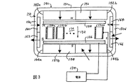
本発明の1つの実施形態によるスパッタイオンポンプの単純化した模式図を図3に示す。陽極セル120a、120b、・・、120nは、陰極板124と126との間に、それらから間隔をあけて配置されている。イオンポンプは1つ以上の陽極セルを含んでいてもよい。各陽極セルは円筒形を有していてもよく、ステンレス鋼で作られていてもよい。陽極セル120a、120b、・・、120nは、それらの軸が互いに平行で、かつ陰極板124,126に垂直になるように向けられている。陰極板124,126は例えばチタンまたはタンタルで作ることができる。電源130は、陰極板124,126と陽極セル120a、120b、・・、120nとの間に、典型的には3kVないし9kVの電圧を印加する。陰極板124と126とは互いに電気的に接続されており、陽極セル120a、120b、・・、120nは互いに電気的に接続されている。陰極板124と126とは基準電圧、この実施形態では接地電位に接続されているものとすることができる。
A simplified schematic diagram of a sputter ion pump according to one embodiment of the present invention is shown in FIG. The
磁石アセンブリ140は陽極セル120a、120b、・・、120nの両端に配置された一次磁石142および144と、磁石ヨーク150とを含む。更に磁石アセンブリ140は陽極セル120a、120b、・・、120nの側方で一次磁石142および144の縁の近傍に配置された二次磁石160,162,164および166を含む。図示のように、一次磁石142は陽極セル120a、120b、・・、120nと対向するN極を有していてもよく、一次磁石144は陽極セル120a、120b、・・、120nと対向するS極を有していてもよい。二次磁石160と164とは陽極セルと対向するN極を有していてもよく、それぞれ一次磁石142の縁142aおよび142bに隣接する陽極セルの両側に配置されている。二次磁石162と166は、陽極セルと対向するS極を有していてもよく、それぞれ一次磁石144の縁144aおよび144bに隣接する陽極セルの両側に配設されている。一次磁石142および144と二次磁石160,162,164および166とのこの配置により、強度が実質的に一様で、実質的に一様に軸方向に向いた磁界132が陽極セル120a、120b、・・、120n内に発生し、それによりスパッタイオンポンプのポンピング速度が向上する。好適には、磁界は陽極セルを横切る間の変動幅が約10%以内の一様な強度を有し、陽極セルを横切る間の変動幅が約15度以内の一様な軸方向を有する。ただし本発明はこれらの範囲に限定されない。
図3に示すように、磁石ヨーク150は端部150a、150bと側方部150c、150dとを含む大略的に長方形の形状を有していてもよく、これにより一次および二次磁石、陰極板ならびに陽極セルを含む内部領域170が規定されている。図3の実施形態において、磁石ヨーク150の端部150aの内面に一次磁石142が取り付けられており、また磁石ヨーク150の端部150bの内面に一次磁石144が取り付けられている。磁石ヨーク150の側方部150cの内面に二次磁石160および162が取り付けられており、また磁石ヨーク150の側方部150dの内面に二次磁石164および166が取り付けられている。従って、互いに反対の極性を有する二次磁石160と162とが磁石ヨーク150の側方部150cの上に配置されており、互いに反対の極性を有する二次磁石164と166とが磁石ヨーク150の側方部150dの上に配置されている。二次磁石160,162,164および166の各々が同じ極性を有する一次磁石に隣接して配設されている。
As shown in FIG. 3, the
図3の特徴を組み込んだスパッタイオンポンプアセンブリの実施形態の側面図と上面図とを、それぞれ図4と図5とに示す。図3〜図5において、類似の要素には同じ参照符号を付している。接続フランジ202を有する真空外囲200が、陰極板124,126および陽極セル120a、120b、・・、120nの領域を取り囲んでいる。高電圧供給部204により、電源130を陰極板124,126と陽極セル120a、120b、・・、120nとに接続することができる。磁石アセンブリ140の構成要素は、図5に最もよく示されるように真空外囲200の外側に配置されていてもよい。
Side and top views of an embodiment of a sputter ion pump assembly incorporating the features of FIG. 3 are shown in FIGS. 4 and 5, respectively. 3 to 5, similar elements are denoted by the same reference numerals. A
図3に示され、また上で述べた二次磁石160、162、164および166は、陽極セル120a、120b、・・、120nの領域内の磁界強度と磁界の形とを最適化する。この改良された磁石アセンブリにより、従来のイオンポンプと比べて高い磁界強度が実現され、それによってより高いポンピング速度が直接得られる。改良された磁石アセンブリはそれに加えて、一次磁石142,144の全磁極幅にわたって質の高い磁界を与え、その結果すべての陽極セルが高速でポンピングを行う。一次磁石142,144の全幅にわたって良好な磁界方向と高い磁界強度とが維持される。これらの特性が両方とも、ポンピング速度の向上、特に低い真空圧力での向上をもたらす。
The
図6、図7および図8は、図3に示した磁石アセンブリと、図2に示した従来の磁石アセンブリとを使用して、毎秒25リットルのイオンポンプの窒素ポンピング速度を測定した結果を示す。ポンピング速度は、ミリバール(Torr)を単位とする入口側圧力の関数としてプロットしている。図6は供給電圧が3kVのときの動作を、図7は供給電圧が5kVのときの動作を、そして図8は供給電圧が7kVのときの動作を示す。イオンポンピング速度は、ISO/DIS 3556−1.2に準拠したFischer-Momsenドーム内で測定した。図6において、曲線300は図3の磁石アセンブリによるイオンポンピング速度を表し、曲線302は図2の磁石アセンブリによるポンピング速度を表す。図7において、曲線310は図3の磁石アセンブリによるポンピング速度を表し、曲線312は図2の磁石アセンブリによるポンピング速度を表わす。図8において、曲線320は図3の磁石アセンブリによるポンピング速度を表し、曲線322は図2の磁石アセンブリによるポンピング速度を表す。図3の改良された磁石アセンブリでのポンピング速度は、全ての真空圧力において、また広い動作電圧範囲に対して高くなっている。
6, 7 and 8 show the results of measuring the nitrogen pumping rate of an ion pump of 25 liters per second using the magnet assembly shown in FIG. 3 and the conventional magnet assembly shown in FIG. . The pumping rate is plotted as a function of inlet pressure in millibars (Torr). FIG. 6 shows the operation when the supply voltage is 3 kV, FIG. 7 shows the operation when the supply voltage is 5 kV, and FIG. 8 shows the operation when the supply voltage is 7 kV. The ion pumping rate was measured in a Fischer-Momsen dome according to ISO / DIS 3556-1.2. In FIG. 6,
陽極セルのポンピング速度はいくつかの要因に依存して変化する。しかしポンピング速度方程式における主なパラメータの1つは磁界強度である。上に述べた改良された磁石アセンブリは、いくつかの理由により向上したポンピング速度を生じる。本分野で周知のように、スパッタイオンポンプには2つのイオンポンピングモードが関連している。それはHMF(高磁界モード)とLMF(低磁界モード)とであり、最高のイオンポンピング速度がHMFモードで実現される。HMFからLMFモードへの転移は、臨界真空圧力と、次式で計算される磁界転移点で起きる。 The pumping speed of the anode cell varies depending on several factors. However, one of the main parameters in the pumping rate equation is the magnetic field strength. The improved magnet assembly described above results in improved pumping speed for several reasons. As is well known in the art, two ion pumping modes are associated with sputter ion pumps. They are HMF (high magnetic field mode) and LMF (low magnetic field mode), and the highest ion pumping speed is realized in the HMF mode. The transition from the HMF to the LMF mode occurs at the critical vacuum pressure and the magnetic field transition point calculated by the following equation.
![]()
![]()
ここでUaは印加電圧であり、Raは陽極セルの半径であり、またPは真空圧力である。真空圧力が低下すると、転移点が上昇する。ある点で、転移点の値はセル内の実際の磁界強度を越える。するとポンピング動作はHMFからLMFモードに切り替わり、実効イオンポンピング速度が低下する。そのため、可能な限り低い圧力までHMFモードを維持することが望ましい。転移点よりも上では、陽極セル内の高い磁界強度がHMFポンピングモードを維持し、最高のポンピング速度を低い真空圧力まで維持する。 Where Ua is the applied voltage, Ra is the radius of the anode cell, and P is the vacuum pressure. As the vacuum pressure decreases, the transition point increases. At some point, the transition point value exceeds the actual field strength in the cell. Then, the pumping operation is switched from HMF to LMF mode, and the effective ion pumping speed is reduced. Therefore, it is desirable to maintain the HMF mode up to the lowest possible pressure. Above the transition point, the high magnetic field strength in the anode cell maintains the HMF pumping mode and maintains the highest pumping speed to a low vacuum pressure.
転移点の磁界強度が陽極セル内の実際の磁界強度を越えると、LMFポンピングモードが始まる。LMFモードは低真空圧力での主要なポンピングモードである。LMFモードでのポンピング速度Sは次式で与えられる。 When the magnetic field strength at the transition point exceeds the actual magnetic field strength in the anode cell, the LMF pumping mode begins. The LMF mode is the main pumping mode at low vacuum pressure. The pumping speed S in the LMF mode is given by the following equation.
![]()
![]()
ここでPは真空圧力であり、Laは陽極セルの長さであり、Raは陽極セルの半径であり、そしてBはガウスで表した磁界強度である。速度が磁界強度の2乗で増加し、磁界強度がわずか増加しただけでもLMFポンピング速度が大幅に増加することがわかる。上記の両方の理由により、磁界強度が増加したときに高いイオンポンピング速度が実現する。
それに加えて、磁界の質も高いポンピング速度にとって重要である。磁界の強度が1群の陽極セルにわたって変化していると、磁界強度が低い場所、または磁束線が陽極セルの軸方向からずれた場所でポンピング作用が低下する。従来のイオンポンプの磁石アセンブリでは、一次磁石の縁の近傍で磁界強度の低下と磁界の向きの乱れとの両方が発生し、その結果一次磁石の縁の近傍における陽極セル内のポンピング速度が低下する。ここに開示する改良された磁石アセンブリは、一次磁石の幅全体にわたって非常に一定した磁界の質を提供し、その結果全てのポンプセル内で高い速度が維持される。これにより、作動中のポンプにおいて高い総合的ポンピング速度が得られる。
Where P is the vacuum pressure, La is the length of the anode cell, Ra is the radius of the anode cell, and B is the magnetic field strength in Gauss. It can be seen that the speed increases with the square of the magnetic field strength, and that the LMF pumping speed significantly increases even with a slight increase in the magnetic field strength. For both reasons above, a high ion pumping rate is achieved when the magnetic field strength is increased.
In addition, the quality of the magnetic field is also important for high pumping speeds. If the strength of the magnetic field varies across a group of anode cells, the pumping action is reduced at locations where the magnetic field strength is low or where the magnetic flux lines are offset from the axial direction of the anode cells. In conventional ion pump magnet assemblies, both a decrease in magnetic field strength and a disturbance in the direction of the magnetic field occur near the edge of the primary magnet, resulting in a decrease in pumping speed in the anode cell near the edge of the primary magnet. To do. The improved magnet assembly disclosed herein provides a very constant magnetic field quality across the width of the primary magnet so that high speed is maintained in all pump cells. This gives a high overall pumping speed in the pump in operation.
更にまた真空圧力が低い場合、例えば10-8Torr以下のとき、電離すべき陽極セル容積中の気体分子が少ない。そのためプラズマ、そしてまたポンピング作用を維持するための二次電子の発生が少なくなる。いくつかの陽極セルが消滅して全くポンピング作用を行わないという場合が生じうる。例えば10-9Torr〜10-12Torrという低い真空圧力では、セル内の空間中に電子を捕捉し、それによりポンピング作用を維持する上で、高い磁界がより効果的である。 Furthermore, when the vacuum pressure is low, for example, 10 −8 Torr or less, there are few gas molecules in the anode cell volume to be ionized. This reduces the generation of plasma and also secondary electrons to maintain the pumping action. There may be cases where some anode cells disappear and do not perform any pumping action. For example, at low vacuum pressures of 10 −9 Torr to 10 −12 Torr, a high magnetic field is more effective in trapping electrons in the space within the cell and thereby maintaining the pumping action.
二次的な効果として、イオンポンプの始動も改善される。10-7Torr以下の真空圧力ではプラズマを発生させる電離の起きる確率が低いので、イオンポンプは運転開始が困難である。磁界をより強くすれば電子をより効果的に捕捉するので、ポンプセル中での電離が大幅に向上し、従ってイオンポンプの運転開始が改善される。
図3〜図5の実施形態は、2個の一次磁石と4個の二次磁石とを含む6個の磁石を含む。一次磁石は陽極セルの領域内に一次磁界を発生させる。一次磁石142および144はそれぞれ、磁石ヨーク150の両端に1つのN極と1つのS極とを有する磁性材料からなる一体のものであってよい。一次磁石は各々互いに並んだ2個以上の磁石要素を含んでもよい。後者の構成は製造コストを下げることができる。好適な実施形態ではフェライト磁石を使用するが、電磁石またはサマリウム−コバルトのような希土類磁石を使用してもよい。陽極セルは半径が約1mm〜50mm、長さが1mm〜50mmの範囲であってもよい。好適な実施形態では図3に示すように6個の磁石を含む。しかし磁石アセンブリは10個の磁石を使用してもよく、その場合2個の追加の二次磁石を陽極構造の上に、また2個の追加の二次磁石を陽極構造の下に有して6辺構造の磁石箱を構成し、それが更に陽極セルの領域中に磁界を包含するようにできる。磁石は、約1mm〜50mmの厚みを有していてもよく、イオンポンプの陽極構造よりもわずかに大きな幅および高さを有していてもよい。あるいは、陽極構造の上と下とに磁性鉄板を使用して磁界を閉じ込め、ポンプの外側の領域への磁界の漏洩を低減し、陽極セル内の空間中により一様な磁界を発生させてもよい。好適な実施形態では、幅が1cmから数cmの一次磁極間隙を使用することもできる。イオンポンプアセンブリ全体を真空外囲内に包含させて接続フランジを使用して真空システムに取り付けるか、または大きな真空システム内に内蔵してもよい。
As a secondary effect, the starting of the ion pump is also improved. Since the probability of ionization that generates plasma is low at a vacuum pressure of 10 −7 Torr or less, it is difficult to start the ion pump. The stronger the magnetic field captures the electrons more effectively, so that the ionization in the pump cell is greatly improved, thus improving the start-up of the ion pump.
The embodiment of FIGS. 3-5 includes six magnets including two primary magnets and four secondary magnets. The primary magnet generates a primary magnetic field in the region of the anode cell. Each of the
磁石ヨーク150は磁束の帰還経路を与える。ヨークは、戻りの磁束をヨーク内に集中させて陽極セル内の空間中での磁極の間の磁界強度を最大にするように構成されている。この構成はまた、実験装置内の荷電粒子ビームや粒子加速器、またはRF電力管のように、イオンポンプが取り付けられるシステムに対して干渉する可能性のある、ポンプ空間外の漏れ磁界をも低減する。ヨーク150は、AISI 1006またはAISI 1010の低炭素鋼または市販の合金鋼のような透磁率の高い材料で作ることができる。一次および二次磁石の厚みおよび幅、磁石ヨークの厚みおよび形状、ならびに磁石間の距離は、最適な磁界強度および磁界の質を得るように調整することができる。ポンピングに対する様々な要求、様々な種類の気体、動作圧力の違い、および物理的な空間的要求の違いをもつイオンポンプには、このような最適化が必要となるであろう。
The
様々なスパッタイオンポンプの構成が知られている。図9に、図3〜図5に図示し上に述べたスパッタイオンポンプに対応する2極スパッタイオンポンプの単純化した模式図を示す。図3〜図5および図9において同様の要素には同じ参照符号を付している。図9では簡単のために磁石アセンブリは省略している。ただし図9の2極スパッタイオンポンプは図3〜図5に図示し上に述べたように磁石アセンブリを含んでもよい。 Various sputter ion pump configurations are known. FIG. 9 shows a simplified schematic diagram of a bipolar sputter ion pump corresponding to the sputter ion pump shown in FIGS. 3 to 5 and described above. Similar elements in FIGS. 3 to 5 and 9 are denoted by the same reference numerals. In FIG. 9, the magnet assembly is omitted for simplicity. However, the bipolar sputtering ion pump of FIG. 9 may include a magnet assembly as shown in FIGS. 3-5 and described above.
図9に示すように、真空外囲200には陰極板124および126が取り付けられており、真空外囲200は接地電位のような基準電圧に接続されている。陽極セル120a、120b等には電源130によってプラスのバイアス電圧がかけられている。陰極板124および126は陽極セル120a、120b等から間隔を開けて配置されている。
図10に、3極スパッタイオンポンプの模式図を示す。図9および図10において同様の要素には同じ参照符号を付している。3極スパッタイオンポンプは陽極セル120a、120b、・・、120nの第一の端部から離して置かれたグリッド陰極400と、陽極セル120a、120b、・・、120nの第二の端部から離して置かれたグリッド陰極402とを含む。グリッド陰極400および402は真空外囲200から離して置かれている。図10の3極イオンポンプでは、陽極セル120a、120b、・・、120nと真空外囲200とは接地電位のような基準電圧に接続されている。グリッド陰極400および402には電源130によってマイナスのバイアス電圧がかけられている。
As shown in FIG. 9,
FIG. 10 shows a schematic diagram of a three-pole sputter ion pump. In FIG. 9 and FIG. 10, the same reference numerals are assigned to the same elements. The triode sputter ion pump is constructed from a
円筒形の陽極セルを有するスパッタイオンポンプを説明してきた。しかしその他の多くの陽極セル形状が知られている。一般に陽極セルは円形、正方形その他任意の形状の断面を有していてもよい。「スターセル」として知られるスパッタイオンポンプの形状は、星型のパターンに形成された陰極を使用する。スターセル型のスパッタイオンポンプはVarian Inc.が製造・販売している。別の陽極セル形状では、波形の形状に形成されて互いに組み合わされて陽極セルを構成する複数の金属片を使用する。陽極セルの断面形状は要素金属片の形状に依存するが、楕円または変形した円に似たものであってもよい。 A sputter ion pump having a cylindrical anode cell has been described. However, many other anode cell shapes are known. In general, the anode cell may have a circular, square or other arbitrary cross section. The shape of a sputter ion pump known as a “star cell” uses a cathode formed in a star pattern. The star cell type sputter ion pump is manufactured and sold by Varian Inc. In another anode cell shape, a plurality of metal pieces that are formed in a corrugated shape and are combined with each other to form the anode cell are used. The cross-sectional shape of the anode cell depends on the shape of the element metal piece, but may be similar to an ellipse or a deformed circle.
図3〜図5に図示し上に述べた磁石アセンブリは、2極構成および3極構成を含むがそれらに限定されない任意のスパッタイオンポンプ構成で利用できることが理解されるであろう。更に、図3〜図5に図示し上に述べた磁石アセンブリは、任意の陽極セル構成で使用できる。ここで説明した磁石アセンブリは任意のスパッタイオンポンプ構成で使用して、実質的に一様な強度を有し、陽極セル内で実質的に一様な軸方向を有する磁界を発生することができる。 It will be appreciated that the magnet assembly shown in FIGS. 3-5 and described above may be utilized in any sputter ion pump configuration including, but not limited to, a 2-pole configuration and a 3-pole configuration. Furthermore, the magnet assembly shown in FIGS. 3-5 and described above can be used in any anode cell configuration. The magnet assembly described herein can be used in any sputter ion pump configuration to generate a magnetic field having a substantially uniform strength and having a substantially uniform axial direction within the anode cell. .
本発明の少なくとも1つの実施形態のいくつかの局面を説明してきたが、当業者には様々な変更、修正および改良を容易に思いつくことができるものと認識される。かかる変更、修正および改良は本開示の一部であることが意図されており、本発明の趣旨および範囲に含まれることが意図されている。従って上記の説明と図示とは単なる例示に過ぎない。 While several aspects of at least one embodiment of the present invention have been described, it will be appreciated by those skilled in the art that various changes, modifications and improvements can be readily devised. Such alterations, modifications, and improvements are intended to be part of this disclosure, and are intended to be within the spirit and scope of the invention. Therefore, the above description and illustration are merely examples.
Claims (19)
内部領域を規定する第一および第二の側方部と第一および第二の端部とを有する磁石ヨークと、
前記磁石ヨークの前記第一および第二の端部に配置された互いに反対の極性を有する一次磁石と、
前記磁石ヨークの前記第一および第二の側方部に配置された二次磁石とを含む磁石アセンブリ。 A magnet assembly used in an ion pump,
A magnet yoke having first and second lateral portions and first and second ends defining an interior region;
Primary magnets having opposite polarities disposed at the first and second ends of the magnet yoke;
And a secondary magnet disposed on the first and second lateral portions of the magnet yoke.
前記1個以上の陽極ポンプセルに近接して配置された陰極であって、前記陰極と前記1個以上の陽極ポンプセルとの間に電界が印加される陰極と、
前記1個以上の陽極ポンプセル中に磁界を発生させる磁石アセンブリとを含み、
前記磁石アセンブリが、
前記陽極ポンプセルの両端に配置された互いに反対の極性を有する一次磁石と、
前記陽極ポンプセルの両側方に配置された二次磁石とを含むイオンポンプ。 One or more anode pump cells;
A cathode disposed proximate to the one or more anode pump cells, wherein a cathode is applied with an electric field between the cathode and the one or more anode pump cells;
A magnet assembly for generating a magnetic field in the one or more anode pump cells,
The magnet assembly comprises:
A primary magnet having opposite polarities disposed at both ends of the anode pump cell;
An ion pump including a secondary magnet disposed on both sides of the anode pump cell.
前記陰極と 前記1つ以上の陽極ポンプセルとの間に電界を印加すること、および
前記陽極ポンプセルの両端に配置された一次磁石と前記陽極ポンプセルの両側方に配置された二次磁石とを含む磁石アセンブリによって、前記1つ以上の陽極ポンプセル内に磁界を発生させることを含む方法。 A method of operating an ion pump including one or more anode pump cells and a cathode comprising:
A magnet including applying an electric field between the cathode and the one or more anode pump cells; and a primary magnet disposed at both ends of the anode pump cell and a secondary magnet disposed on both sides of the anode pump cell. Generating a magnetic field in the one or more anode pump cells by an assembly.
内部領域を規定する第一および第二の側方部と第一および第二の端部とを有する磁石ヨークと、
前記磁石ヨークの前記第一および第二の端部にそれぞれ配置された第一の一次磁石を含む互いに反対の極性を有する一次磁石と、
前記磁石ヨークの前記第一の側方部に配置された互いに反対の極性を有する第一および第二の二次磁石と、前記磁石ヨークの前記第二の側方部に配置された互いに反対の極性を有する第三および第四の二次磁石とを含む二次磁石であって、各々の二次磁石が同じ極性の一次磁石に隣接して配置されている二次磁石とを含む磁石アセンブリ。 A magnet assembly used in an ion pump,
A magnet yoke having first and second lateral portions and first and second ends defining an interior region;
Primary magnets having opposite polarities including first primary magnets respectively disposed at the first and second ends of the magnet yoke;
First and second secondary magnets having opposite polarities disposed on the first side portion of the magnet yoke and opposite to each other disposed on the second side portion of the magnet yoke A magnet assembly including a secondary magnet including third and fourth secondary magnets having polarity, each secondary magnet being disposed adjacent to a primary magnet of the same polarity.
Applications Claiming Priority (2)
| Application Number | Priority Date | Filing Date | Title |
|---|---|---|---|
| US10/322,991 US6835048B2 (en) | 2002-12-18 | 2002-12-18 | Ion pump having secondary magnetic field |
| PCT/US2003/037878 WO2004061889A2 (en) | 2002-12-18 | 2003-11-25 | Magnet assembly for sputter ion pump |
Publications (2)
| Publication Number | Publication Date |
|---|---|
| JP2006511921A true JP2006511921A (en) | 2006-04-06 |
| JP2006511921A5 JP2006511921A5 (en) | 2007-02-08 |
Family
ID=32593082
Family Applications (1)
| Application Number | Title | Priority Date | Filing Date |
|---|---|---|---|
| JP2004565119A Pending JP2006511921A (en) | 2002-12-18 | 2003-11-25 | Magnet assembly for sputter ion pump |
Country Status (7)
| Country | Link |
|---|---|
| US (1) | US6835048B2 (en) |
| EP (1) | EP1573773B1 (en) |
| JP (1) | JP2006511921A (en) |
| CN (1) | CN100369178C (en) |
| DE (1) | DE60313888T2 (en) |
| ES (1) | ES2282728T3 (en) |
| WO (1) | WO2004061889A2 (en) |
Cited By (1)
| Publication number | Priority date | Publication date | Assignee | Title |
|---|---|---|---|---|
| WO2022264603A1 (en) * | 2021-06-14 | 2022-12-22 | 国立研究開発法人産業技術総合研究所 | Plasma source, and atomic clock employing said plasma source |
Families Citing this family (13)
| Publication number | Priority date | Publication date | Assignee | Title |
|---|---|---|---|---|
| EP1863068B1 (en) * | 2006-06-01 | 2008-08-13 | VARIAN S.p.A. | Magnet assembly for a sputter ion pump |
| US20070286738A1 (en) * | 2006-06-12 | 2007-12-13 | Varian, Inc. | Vacuum ion-getter pump with cryogenically cooled cathode |
| US7850432B2 (en) * | 2006-09-14 | 2010-12-14 | Gamma Vacuum, Llc | Ion pump having emission containment |
| WO2008099612A1 (en) * | 2007-02-16 | 2008-08-21 | National Institute Of Information And Communications Technology | Vacuum conveyance system |
| WO2009101814A1 (en) * | 2008-02-14 | 2009-08-20 | National Institute Of Information And Communications Technology | Ion pump system and electromagnetic field generator |
| EP2151849B1 (en) | 2008-08-08 | 2011-12-14 | Agilent Technologies Italia S.p.A. | Vacuum pumping system comprising a plurality of sputter ion pumps |
| US8153997B2 (en) * | 2009-05-05 | 2012-04-10 | General Electric Company | Isotope production system and cyclotron |
| US8374306B2 (en) | 2009-06-26 | 2013-02-12 | General Electric Company | Isotope production system with separated shielding |
| US8453493B2 (en) | 2010-11-02 | 2013-06-04 | Agilent Technologies, Inc. | Trace gas sensing apparatus and methods for leak detection |
| CN104952685B (en) * | 2015-01-19 | 2017-11-21 | 中国航天员科研训练中心 | The big pumping speed ionic pump of lightweight |
| US10665437B2 (en) * | 2015-02-10 | 2020-05-26 | Hamilton Sundstrand Corporation | System and method for enhanced ion pump lifespan |
| US10550829B2 (en) * | 2016-09-08 | 2020-02-04 | Edwards Vacuum Llc | Ion trajectory manipulation architecture in an ion pump |
| CN110491764B (en) * | 2019-09-02 | 2022-03-29 | 北京卫星环境工程研究所 | Magnetic yoke assembly of sputtering ion pump |
Citations (6)
| Publication number | Priority date | Publication date | Assignee | Title |
|---|---|---|---|---|
| JPS58193557U (en) * | 1982-06-18 | 1983-12-23 | 三菱製鋼磁材株式会社 | Magnet device for ion pump |
| JPS61218120A (en) * | 1985-03-23 | 1986-09-27 | Sumitomo Special Metals Co Ltd | Magnetic field generator |
| JPS62177903A (en) * | 1986-01-31 | 1987-08-04 | Fuji Electric Co Ltd | Permanent magnet type uniform magnetic-field magnet |
| JPH01502632A (en) * | 1987-03-03 | 1989-09-07 | コミッサレ・ア・レナジイ・アトミック | permanent magnet device |
| JPH0822803A (en) * | 1994-07-08 | 1996-01-23 | Ulvac Japan Ltd | Sputter ion pump |
| JPH0927294A (en) * | 1995-07-12 | 1997-01-28 | Ebara Corp | Ion pump |
Family Cites Families (11)
| Publication number | Priority date | Publication date | Assignee | Title |
|---|---|---|---|---|
| US3091717A (en) * | 1957-07-24 | 1963-05-28 | Varian Associates | Cathodes for magnetically-confined glow discharge devices |
| GB924919A (en) * | 1958-06-16 | 1963-05-01 | Varian Associates | Electrical vacuum pump apparatus |
| NL232314A (en) * | 1958-10-15 | |||
| US3416722A (en) * | 1967-04-05 | 1968-12-17 | Varian Associates | High vacuum pump employing apertured penning cells driving ion beams into a target covered by a getter sublimator |
| US3994625A (en) * | 1975-02-18 | 1976-11-30 | Varian Associates | Sputter-ion pump having improved cooling and improved magnetic circuitry |
| US4334829A (en) * | 1980-02-15 | 1982-06-15 | Rca Corporation | Sputter-ion pump for use with electron tubes having thoriated tungsten cathodes |
| US4672346A (en) * | 1984-04-11 | 1987-06-09 | Sumotomo Special Metal Co., Ltd. | Magnetic field generating device for NMR-CT |
| US5262028A (en) * | 1992-06-01 | 1993-11-16 | Sierra Applied Sciences, Inc. | Planar magnetron sputtering magnet assembly |
| CN1166811C (en) * | 1996-01-05 | 2004-09-15 | 日本真空技术株式会社 | Sputter-ion pump |
| US6004104A (en) * | 1997-07-14 | 1999-12-21 | Duniway Stockroom Corp. | Cathode structure for sputter ion pump |
| CN1366706A (en) * | 2000-03-13 | 2002-08-28 | 爱发科股份有限公司 | Spatter ion pump |
-
2002
- 2002-12-18 US US10/322,991 patent/US6835048B2/en not_active Expired - Lifetime
-
2003
- 2003-11-25 JP JP2004565119A patent/JP2006511921A/en active Pending
- 2003-11-25 DE DE60313888T patent/DE60313888T2/en not_active Expired - Lifetime
- 2003-11-25 ES ES03796479T patent/ES2282728T3/en not_active Expired - Lifetime
- 2003-11-25 WO PCT/US2003/037878 patent/WO2004061889A2/en active IP Right Grant
- 2003-11-25 CN CNB2003801002428A patent/CN100369178C/en not_active Expired - Fee Related
- 2003-11-25 EP EP03796479A patent/EP1573773B1/en not_active Expired - Lifetime
Patent Citations (6)
| Publication number | Priority date | Publication date | Assignee | Title |
|---|---|---|---|---|
| JPS58193557U (en) * | 1982-06-18 | 1983-12-23 | 三菱製鋼磁材株式会社 | Magnet device for ion pump |
| JPS61218120A (en) * | 1985-03-23 | 1986-09-27 | Sumitomo Special Metals Co Ltd | Magnetic field generator |
| JPS62177903A (en) * | 1986-01-31 | 1987-08-04 | Fuji Electric Co Ltd | Permanent magnet type uniform magnetic-field magnet |
| JPH01502632A (en) * | 1987-03-03 | 1989-09-07 | コミッサレ・ア・レナジイ・アトミック | permanent magnet device |
| JPH0822803A (en) * | 1994-07-08 | 1996-01-23 | Ulvac Japan Ltd | Sputter ion pump |
| JPH0927294A (en) * | 1995-07-12 | 1997-01-28 | Ebara Corp | Ion pump |
Cited By (1)
| Publication number | Priority date | Publication date | Assignee | Title |
|---|---|---|---|---|
| WO2022264603A1 (en) * | 2021-06-14 | 2022-12-22 | 国立研究開発法人産業技術総合研究所 | Plasma source, and atomic clock employing said plasma source |
Also Published As
| Publication number | Publication date |
|---|---|
| US6835048B2 (en) | 2004-12-28 |
| US20040120826A1 (en) | 2004-06-24 |
| DE60313888T2 (en) | 2008-01-17 |
| DE60313888D1 (en) | 2007-06-28 |
| EP1573773A2 (en) | 2005-09-14 |
| CN100369178C (en) | 2008-02-13 |
| EP1573773B1 (en) | 2007-05-16 |
| WO2004061889A2 (en) | 2004-07-22 |
| WO2004061889A3 (en) | 2004-09-30 |
| CN1708822A (en) | 2005-12-14 |
| ES2282728T3 (en) | 2007-10-16 |
Similar Documents
| Publication | Publication Date | Title |
|---|---|---|
| JP2006511921A (en) | Magnet assembly for sputter ion pump | |
| JP5822767B2 (en) | Ion source apparatus and ion beam generating method | |
| US6616417B2 (en) | Spatter ion pump | |
| Zelenski et al. | High-intensity polarized and un-polarized sources and injector developments at BNL Linac | |
| EP1863068B1 (en) | Magnet assembly for a sputter ion pump | |
| JP2011003425A (en) | Ion pump | |
| US20180306175A1 (en) | Magnetic focusing in an ion pump using internal ferrous materials | |
| JP3147227B2 (en) | Cold cathode electron gun | |
| Dudnikov | An H Surface Plasma Source for the ESS Storage Ring | |
| US3452923A (en) | Tetrode ion pump | |
| RU76164U1 (en) | DISCHARGE SOURCE OF IONS | |
| US10358713B2 (en) | Surrounding field sputtering source | |
| RU76163U1 (en) | DISCHARGE SOURCE OF IONS | |
| CN112582248B (en) | Electron gun device for mercury ion microwave frequency standard | |
| RU2233505C2 (en) | Gas-discharge ion source | |
| RU2352013C2 (en) | Source of ions with multipole magnetic field in hollow cathode | |
| Gavrilov et al. | Ion-Emission Properties of a Plasma in a Gaseous-Ion Source with a Plasma Cathode. | |
| RU2205467C2 (en) | Ion source | |
| JPS5911175B2 (en) | ion source | |
| JPS63121242A (en) | Sputter ion pump for accelerator | |
| RU2371804C1 (en) | Gas-discharge ion source | |
| JP4639027B2 (en) | Sputter ion pump | |
| JPH0580095B2 (en) | ||
| Oka et al. | H? Ion Source Using a Local Magnetic Filter in the Plasma Electrode: Type I LV Magnetic Filter H? Source | |
| JPH07263194A (en) | Accelerator |
Legal Events
| Date | Code | Title | Description |
|---|---|---|---|
| A521 | Request for written amendment filed |
Free format text: JAPANESE INTERMEDIATE CODE: A523 Effective date: 20061121 |
|
| A621 | Written request for application examination |
Free format text: JAPANESE INTERMEDIATE CODE: A621 Effective date: 20061121 |
|
| A131 | Notification of reasons for refusal |
Free format text: JAPANESE INTERMEDIATE CODE: A131 Effective date: 20091106 |
|
| A02 | Decision of refusal |
Free format text: JAPANESE INTERMEDIATE CODE: A02 Effective date: 20100408 |