JP2006507703A - Communication bridge between vehicle information network and remote system - Google Patents
Communication bridge between vehicle information network and remote system Download PDFInfo
- Publication number
- JP2006507703A JP2006507703A JP2003572271A JP2003572271A JP2006507703A JP 2006507703 A JP2006507703 A JP 2006507703A JP 2003572271 A JP2003572271 A JP 2003572271A JP 2003572271 A JP2003572271 A JP 2003572271A JP 2006507703 A JP2006507703 A JP 2006507703A
- Authority
- JP
- Japan
- Prior art keywords
- port
- usb
- communication
- adapter
- interface
- Prior art date
- Legal status (The legal status is an assumption and is not a legal conclusion. Google has not performed a legal analysis and makes no representation as to the accuracy of the status listed.)
- Pending
Links
Images


Classifications
-
- B—PERFORMING OPERATIONS; TRANSPORTING
- B60—VEHICLES IN GENERAL
- B60R—VEHICLES, VEHICLE FITTINGS, OR VEHICLE PARTS, NOT OTHERWISE PROVIDED FOR
- B60R16/00—Electric or fluid circuits specially adapted for vehicles and not otherwise provided for; Arrangement of elements of electric or fluid circuits specially adapted for vehicles and not otherwise provided for
- B60R16/02—Electric or fluid circuits specially adapted for vehicles and not otherwise provided for; Arrangement of elements of electric or fluid circuits specially adapted for vehicles and not otherwise provided for electric constitutive elements
- B60R16/03—Electric or fluid circuits specially adapted for vehicles and not otherwise provided for; Arrangement of elements of electric or fluid circuits specially adapted for vehicles and not otherwise provided for electric constitutive elements for supply of electrical power to vehicle subsystems or for
- B60R16/0315—Electric or fluid circuits specially adapted for vehicles and not otherwise provided for; Arrangement of elements of electric or fluid circuits specially adapted for vehicles and not otherwise provided for electric constitutive elements for supply of electrical power to vehicle subsystems or for using multiplexing techniques
-
- H—ELECTRICITY
- H04—ELECTRIC COMMUNICATION TECHNIQUE
- H04L—TRANSMISSION OF DIGITAL INFORMATION, e.g. TELEGRAPHIC COMMUNICATION
- H04L12/00—Data switching networks
- H04L12/28—Data switching networks characterised by path configuration, e.g. LAN [Local Area Networks] or WAN [Wide Area Networks]
- H04L12/2803—Home automation networks
-
- H—ELECTRICITY
- H04—ELECTRIC COMMUNICATION TECHNIQUE
- H04L—TRANSMISSION OF DIGITAL INFORMATION, e.g. TELEGRAPHIC COMMUNICATION
- H04L12/00—Data switching networks
- H04L12/28—Data switching networks characterised by path configuration, e.g. LAN [Local Area Networks] or WAN [Wide Area Networks]
- H04L12/40—Bus networks
- H04L12/40006—Architecture of a communication node
- H04L12/40013—Details regarding a bus controller
-
- H—ELECTRICITY
- H04—ELECTRIC COMMUNICATION TECHNIQUE
- H04L—TRANSMISSION OF DIGITAL INFORMATION, e.g. TELEGRAPHIC COMMUNICATION
- H04L12/00—Data switching networks
- H04L12/28—Data switching networks characterised by path configuration, e.g. LAN [Local Area Networks] or WAN [Wide Area Networks]
- H04L12/40—Bus networks
- H04L12/403—Bus networks with centralised control, e.g. polling
-
- H—ELECTRICITY
- H04—ELECTRIC COMMUNICATION TECHNIQUE
- H04L—TRANSMISSION OF DIGITAL INFORMATION, e.g. TELEGRAPHIC COMMUNICATION
- H04L12/00—Data switching networks
- H04L12/28—Data switching networks characterised by path configuration, e.g. LAN [Local Area Networks] or WAN [Wide Area Networks]
- H04L12/46—Interconnection of networks
- H04L12/4604—LAN interconnection over a backbone network, e.g. Internet, Frame Relay
- H04L12/462—LAN interconnection over a bridge based backbone
- H04L12/4625—Single bridge functionality, e.g. connection of two networks over a single bridge
-
- H—ELECTRICITY
- H04—ELECTRIC COMMUNICATION TECHNIQUE
- H04L—TRANSMISSION OF DIGITAL INFORMATION, e.g. TELEGRAPHIC COMMUNICATION
- H04L12/00—Data switching networks
- H04L12/66—Arrangements for connecting between networks having differing types of switching systems, e.g. gateways
-
- H—ELECTRICITY
- H04—ELECTRIC COMMUNICATION TECHNIQUE
- H04L—TRANSMISSION OF DIGITAL INFORMATION, e.g. TELEGRAPHIC COMMUNICATION
- H04L43/00—Arrangements for monitoring or testing data switching networks
-
- H—ELECTRICITY
- H04—ELECTRIC COMMUNICATION TECHNIQUE
- H04L—TRANSMISSION OF DIGITAL INFORMATION, e.g. TELEGRAPHIC COMMUNICATION
- H04L67/00—Network arrangements or protocols for supporting network services or applications
- H04L67/01—Protocols
- H04L67/12—Protocols specially adapted for proprietary or special-purpose networking environments, e.g. medical networks, sensor networks, networks in vehicles or remote metering networks
-
- H—ELECTRICITY
- H04—ELECTRIC COMMUNICATION TECHNIQUE
- H04L—TRANSMISSION OF DIGITAL INFORMATION, e.g. TELEGRAPHIC COMMUNICATION
- H04L67/00—Network arrangements or protocols for supporting network services or applications
- H04L67/2866—Architectures; Arrangements
- H04L67/30—Profiles
- H04L67/303—Terminal profiles
-
- H—ELECTRICITY
- H04—ELECTRIC COMMUNICATION TECHNIQUE
- H04L—TRANSMISSION OF DIGITAL INFORMATION, e.g. TELEGRAPHIC COMMUNICATION
- H04L9/00—Cryptographic mechanisms or cryptographic arrangements for secret or secure communications; Network security protocols
- H04L9/40—Network security protocols
-
- H—ELECTRICITY
- H04—ELECTRIC COMMUNICATION TECHNIQUE
- H04L—TRANSMISSION OF DIGITAL INFORMATION, e.g. TELEGRAPHIC COMMUNICATION
- H04L12/00—Data switching networks
- H04L12/28—Data switching networks characterised by path configuration, e.g. LAN [Local Area Networks] or WAN [Wide Area Networks]
- H04L12/40—Bus networks
- H04L2012/40208—Bus networks characterized by the use of a particular bus standard
- H04L2012/40215—Controller Area Network CAN
-
- H—ELECTRICITY
- H04—ELECTRIC COMMUNICATION TECHNIQUE
- H04L—TRANSMISSION OF DIGITAL INFORMATION, e.g. TELEGRAPHIC COMMUNICATION
- H04L12/00—Data switching networks
- H04L12/28—Data switching networks characterised by path configuration, e.g. LAN [Local Area Networks] or WAN [Wide Area Networks]
- H04L12/40—Bus networks
- H04L2012/40267—Bus for use in transportation systems
- H04L2012/40273—Bus for use in transportation systems the transportation system being a vehicle
-
- H—ELECTRICITY
- H04—ELECTRIC COMMUNICATION TECHNIQUE
- H04L—TRANSMISSION OF DIGITAL INFORMATION, e.g. TELEGRAPHIC COMMUNICATION
- H04L69/00—Network arrangements, protocols or services independent of the application payload and not provided for in the other groups of this subclass
- H04L69/30—Definitions, standards or architectural aspects of layered protocol stacks
- H04L69/32—Architecture of open systems interconnection [OSI] 7-layer type protocol stacks, e.g. the interfaces between the data link level and the physical level
- H04L69/322—Intralayer communication protocols among peer entities or protocol data unit [PDU] definitions
- H04L69/329—Intralayer communication protocols among peer entities or protocol data unit [PDU] definitions in the application layer [OSI layer 7]
Landscapes
- Engineering & Computer Science (AREA)
- Signal Processing (AREA)
- Computer Networks & Wireless Communication (AREA)
- Computing Systems (AREA)
- Health & Medical Sciences (AREA)
- Computer Security & Cryptography (AREA)
- General Health & Medical Sciences (AREA)
- Medical Informatics (AREA)
- Mechanical Engineering (AREA)
- Automation & Control Theory (AREA)
- Small-Scale Networks (AREA)
- Communication Control (AREA)
- Information Transfer Systems (AREA)
- Selective Calling Equipment (AREA)
- Bus Control (AREA)
Abstract
1つ以上のエンジン/車両データ・リンク通信プロトコルを、1つ以上のコンピュータ通信プロトコルのいずれにでも変換する通信ブリッジを提供する。自動車に搭載し、第1プロトコルによる通信に対し構成された通信ネットワークと、第1プロトコルによる通信に対し構成されたリモート・システムとの間の通信ブリッジは、通信ネットワークに結合するように構成されている第1インターフェースと、リモート・システムに結合するように構成されている第2インターフェースと、命令サイクル当たり多数の動作を処理するように構成されているディジタル信号プロセッサ(DSP)とを含む。DSPは、第1インターフェースを介して通信ネットワークから情報を受信し、この情報を第2プロトコルに変換し、第2プロトコルに変換した情報を、第2インターフェースを介してリモート・システムに送信する。更に、DSPは、第2インターフェースを介して、リモート・システムから情報を受信し、この情報を第1プロトコルに変換し、第1プロトコルに変換した情報を、第1インターフェースを介して通信ネットワークに送信する。A communication bridge is provided that converts one or more engine / vehicle data link communication protocols into any of the one or more computer communication protocols. A communication bridge between an onboard vehicle configured for communication according to the first protocol and a remote system configured for communication according to the first protocol is configured to couple to the communication network. A first interface configured to couple to the remote system, and a digital signal processor (DSP) configured to process a number of operations per instruction cycle. The DSP receives information from the communication network via the first interface, converts this information to the second protocol, and transmits the information converted to the second protocol to the remote system via the second interface. Further, the DSP receives information from the remote system via the second interface, converts this information to the first protocol, and transmits the information converted to the first protocol to the communication network via the first interface. To do.
Description
本発明は、一般的には、情報通信システムに関し、更に特定すれば、1つ以上の車両情報ネットワークのプロトコルが1つ以上のリモート・システムのプロトコルとは異なる場合に、1つ以上の車両情報ネットワークと1つ以上のリモート・システムとの間で情報交換を行うための通信ブリッジに関する。 The present invention relates generally to information communication systems, and more particularly, one or more vehicle information when the protocol of one or more vehicle information networks is different from the protocol of one or more remote systems. The present invention relates to a communication bridge for exchanging information between a network and one or more remote systems.
関連出願に対する引用
これは、2002年2月25日に出願され、VEHICLE COMMUNICATIONS NETWORK ADAPER(車両通信ネットワーク・アダプタ)と題する、同時係属中の米国特許出願第10/082,196号の一部継続出願である。
Citation to Related Application This is a continuation-in-part of co-pending US patent application Ser. No. 10 / 082,196, filed Feb. 25, 2002 and entitled VEHICLE COMMUNICATIONS NETWORK ADAPER. It is.
自動車は、種々の電子制御コンピュータを含み、車両内に搭載している。制御コンピュータは、車両内における種々のシステムおよび/またはサブシステムを制御することができる。例えば、制御コンピュータは、燃料供給システム、トランスミッション、ブレーキまたは操舵機構を制御することができる。これらの制御コンピュータは、通例、種々のセンサおよび/またはアクチュエータに結合されている。商用車両では、制御コンピュータは、最大速度、燃料使用、最大加速度、使用時間等というような、車両の使用に関するログ・データを含む。このようなシステムは、全地球測地システム(GPS)受信機をも内蔵し、車両がどこを移動したか記録することができる場合もある。 The automobile includes various electronic control computers and is mounted in the vehicle. The control computer can control various systems and / or subsystems in the vehicle. For example, the control computer can control a fuel supply system, transmission, brake or steering mechanism. These control computers are typically coupled to various sensors and / or actuators. In commercial vehicles, the control computer includes log data regarding vehicle usage, such as maximum speed, fuel usage, maximum acceleration, usage time, and the like. Such a system may also incorporate a global geodetic system (GPS) receiver to record where the vehicle has moved.
これらの制御コンピュータは、1つ以上の車両通信ネットワークを通じて、互いに、そして外部サービス機器と通信する。車両通信ネットワーク・プロトコルの規格が開発され、当技術分野では周知である。例えば、自動車技師協会(SAE:Society of Automotive Engineers)は、電子信号を送信し、車両構成部品間において情報を制御するデバイスの設計および使用に関する規格を作成している。これらの規格の一部には、SAE J1939、SAE1850、およびSA J1587/J1708(SAE J1708はRS−485通信ハードウェア構造の具体的な実施形態であり、J1708構造を通じた通信は、SAE J1587によって規制された通信プロトコルにしたがって行うことができ、これは当技術分野では周知である)。国際標準機構が作成したISO−9141のような、他の機構が作成した別の規格もある。 These control computers communicate with each other and with external service equipment through one or more vehicle communication networks. Vehicle communication network protocol standards have been developed and are well known in the art. For example, the Society of Automotive Engineers (SAE) has created standards for the design and use of devices that transmit electronic signals and control information between vehicle components. Some of these standards include SAE J1939, SAE1850, and SA J1587 / J1708 (SAE J1708 is a specific embodiment of the RS-485 communication hardware structure, and communication through the J1708 structure is regulated by SAE J1587. And is well known in the art). There are other standards created by other organizations, such as ISO-9141 created by the International Organization for Standardization.
過去においては、制御コンピュータに伴う問題を診断し、制御コンピュータが記録した情報をダウンロードし、制御コンピュータに情報をアップロードするために、サービス機器を利用していた。例えば、制御コンピュータは、車両最大速度またはの最大トルクを制限することができ、この最大値は、コンピュータを用いたサービス・ツールによってプログラムすることができる。車両によっては、パラメータのホストや、燃料マッピングでさえも、サービス機器によって変更することができる。 In the past, service devices have been used to diagnose problems with the control computer, download information recorded by the control computer, and upload information to the control computer. For example, the control computer can limit the vehicle maximum speed or maximum torque, which can be programmed by a service tool using the computer. Depending on the vehicle, the parameter host and even the fuel mapping can be changed by the service equipment.
サービス機器は、概略的に、自動車に搭載した1つ以上の制御コンピュータに対して双方向で情報を伝達するために用いられるハンドヘルド機器または据え付け機器として類別することができる。ハンドヘルド・サービス・デバイスのことを多くの場合「サービス・ツール」と呼び、特に、車内内蔵コンピュータ・システムに伴う障害を解決するために用いることができる。典型的なサービス・ツールは、中央演算装置(cpu)、およびカスタム・インターフェース回路を含み、車両内においてcpuと1つ以上の制御コンピュータとの間の通信を容易に行うようにしている。多くのサービス・ツールは、「カスタム」製造であり、特定の製造業者が生産した1つ以上の制御コンピュータとのみ、そして多くの場合、特定の製造業者が生産したある種のモデルとのみインターフェースするように設計されている。 Service equipment can generally be categorized as handheld equipment or stationary equipment used to communicate information bidirectionally to one or more control computers installed in a vehicle. Handheld service devices are often referred to as “service tools” and can be used to solve, among other things, the problems associated with in-car computer systems. A typical service tool includes a central processing unit (cpu) and custom interface circuitry to facilitate communication between cpu and one or more control computers in the vehicle. Many service tools are “custom” manufacturing and interface only with one or more control computers produced by a particular manufacturer, and often only with certain models produced by a particular manufacturer. Designed to be
据え付けサービス機器は、一般に、データ・ログを検索するため、およびその他の更に複雑なタスクのために用いられるが、多くの目的のために、ハンドヘルドサービス機器および据え付けサービス機器は相互交換することもできる。最近の据え付けサービス機器の設計は、パーソナル・コンピュータ(PC)を構築している(implement)。1つ以上の車両制御コンピュータをパーソナル・コンピュータ(PC)に結合するための現行の方法では、特注のcpu毎のインターフェースを必要とし、このインターフェースが1つ以上の車両コンピュータの通信プロトコル(即ち、SAE J1939および/またはSAE J1587/J1708)をRS−232(標準的シリアル)またはペリフェラル・コンピュータ・インターフェース(PCI)のようなPC通信規格に変換する。これらのカスタム・インターフェース・アダプタは、通例、PC内に実装されているPCインターフェース・ボード、または1つ以上の車両制御コンピュータとPCとの間に結合される外部「ポッド」を含む。 Stationary service equipment is typically used to retrieve data logs and for other more complex tasks, but for many purposes, handheld service equipment and stationary service equipment can also be interchanged. . Recent design of stationary service equipment is building a personal computer (PC). Current methods for coupling one or more vehicle control computers to a personal computer (PC) require a custom cpu-specific interface, which interface is the communication protocol (ie, SAE) of one or more vehicle computers. J1939 and / or SAE J1587 / J1708) is converted to a PC communication standard such as RS-232 (standard serial) or peripheral computer interface (PCI). These custom interface adapters typically include a PC interface board implemented in the PC, or an external “pod” that is coupled between one or more vehicle control computers and the PC.
多くの製造業者は、今日、自動車用途以外のハンドヘルド・コンピュータを販売している。例えば、パーソナル・ディジタル・アシスタント(PDA)は、ペンを用いたハンドヘルド・コンピュータであり、カレンダや住所録のような個人情報マネージャ(PIM)の機能性を、計算構造と組み合わせている。PDAの殆どは、RS−232シリアル・ポートまたはユニバーサル・シリアル・バス(USB)ポートのいずれかを通じて、「ホスト」コンピュータ、一般にはパーソナル・コンピュータ(PC)と通信するように設計されている。 Many manufacturers today sell handheld computers for non-automotive applications. For example, a personal digital assistant (PDA) is a handheld computer using a pen that combines the functionality of a personal information manager (PIM) such as a calendar or address book with a computational structure. Most PDAs are designed to communicate with a “host” computer, typically a personal computer (PC), through either an RS-232 serial port or a universal serial bus (USB) port.
このようなハンドヘルド・コンピュータ・システムは、転送および分析のためのエンジン/車両情報の抽出、表示、およびアップロードにおいて補助するためのデバイスとして用いることができる。このようなシステムの1つが、”Handheld computer based system for collection, display, and analysis of engine/vehicle data"(エンジン/車両データの収集、表示、および分析のための、ハンドヘルド・コンピュータを用いたシステム)と題する米国特許出願第09/583,892号に記載されている。この出願は、本願と同じ譲受人に譲渡されており、その開示内容はここで引用したことにより本願にも含まれることとする。 Such a handheld computer system can be used as a device to assist in the extraction, display and upload of engine / vehicle information for transfer and analysis. One such system is a “handheld computer based system for collection, display, and analysis of engine / vehicle data”. In US patent application Ser. No. 09 / 583,892. This application is assigned to the same assignee as the present application, the disclosure of which is hereby incorporated herein by reference.
PDAおよびPC双方は、通例、USBポートを含むか、または後付けすることができる。USBポートは、多くの理由で、標準的なシリアル・ポートよりも遥かに多様性がある。例えば、標準的なシリアル・ポートは「1対1」であるので、標準的なシリアル・リンクを通じて通信のために接続できるのは、2つのデバイスのみである。対照的に、USBは多点シリアル・リンクを提供するので、多数のコンピュータを1つのデータ・リンクを通じて通信のために接続することができる。他の例として、標準的なシリアル・ポートは、USBよりも遥かに遅いことが上げられる。標準的なシリアル・ポートにおける最大到達可能速度は、現在115kb/sの範囲である。対照的に、高速USBは400倍以上高速であり、480Mb/sの転送レートを達成し、最大速度のUSBは100倍速く、12Mb/sのデータ・レートを達成している。 Both PDAs and PCs typically include USB ports or can be retrofitted. USB ports are much more versatile than standard serial ports for a number of reasons. For example, since a standard serial port is “one-to-one”, only two devices can be connected for communication through a standard serial link. In contrast, since USB provides a multipoint serial link, multiple computers can be connected for communication through a single data link. As another example, a standard serial port can be much slower than USB. The maximum reachable speed for a standard serial port is currently in the range of 115 kb / s. In contrast, high speed USB is more than 400 times faster and achieves a transfer rate of 480 Mb / s, and maximum speed USB is 100 times faster and achieves a data rate of 12 Mb / s.
しかしながら、多点USBシリアル・リンクに取り付けられるコンピュータは、「デバイス」または「ホスト」のいずれかとして構成されなければならない。多くのデバイスを1つのホストに接続することができる。しかしながら、いずれの1つのリンクにも、2つのホストを直接互いに接続することはできず、2つのデバイスを直接互いに接続することもできない。コンピュータの中には、オンザゴー(OTG:on-the-go)USBポートを含むものもあり、これによって、ポートに挿入されるケーブルのタイプによっては、デバイスとして、または機能を限定したホストとして機能することができる。オンザゴーUSBポートを有するコンピュータは、常にホストに接続することができ(即ち、デバイスとして機能する)、オンザゴーUSBポートを搭載したコンピュータに対応するようにデバイスが構成されているのであれば、デバイスにも接続することができる(即ち、ホストとして機能する)。更に、USBコントローラの一部は、デバイス、ホスト、またはOTGとして動的に構成変更可能なポートを含み、USB構成のいずれに対応するにも、単一のポートだけで済むようになっている。 However, a computer attached to a multipoint USB serial link must be configured as either a “device” or a “host”. Many devices can be connected to one host. However, on any one link, two hosts cannot be directly connected to each other, nor can two devices be directly connected to each other. Some computers include an on-the-go (OTG) USB port, which acts as a device or as a host with limited functionality, depending on the type of cable inserted into the port. be able to. A computer with an on-the-go USB port can always connect to the host (ie, function as a device), and if the device is configured to support a computer with an on-the-go USB port, the device Can connect (ie, function as a host). Furthermore, some USB controllers include ports that can be dynamically reconfigured as devices, hosts, or OTGs, so that only a single port is required to support any USB configuration.
また、USBホスト能力を有する「ポケットPC」、ならびにUSBオンザゴー能力を有するPC、PDA、およびその他のコンピュータ化デバイスも存在する。いずれのUSB計算デバイス(PC、PDA、ポケットPC等)でも、USBホスト、デバイス、またはオンザゴー・ポートのいずれの組み合わせでも有することができる。所与のタイプのコンピュータに含むことができるUSBの可能な組み合わせの範囲を示すことは、本開示においては全く意図するところではない。 There are also “pocket PCs” with USB host capabilities, as well as PCs, PDAs, and other computerized devices with USB on-the-go capabilities. Any USB computing device (PC, PDA, pocket PC, etc.) can have any combination of USB host, device, or on-the-go port. It is not intended at all in this disclosure to indicate the range of possible combinations of USB that can be included in a given type of computer.
USBプロトコルについては、"Universal Serial Bus Specification"(ユニバーサル・シリアル・バス仕様書)、 改訂第2版(2000年4月27日)、"Errata to the USB 2.0 Specification"(USB2.0仕様書の正誤表)(2000年12月7日)、および"On-The-Go Supplement to the USB 2.0 Specification"(USB2.0仕様書に対するオンザゴー補足)、改訂第1版(2001年12月18日)に記載されており、これら3つの内容は、ここで引用したことにより、本願にも含まれることとする。 Regarding USB protocol, “Universal Serial Bus Specification”, second revised edition (April 27, 2000), “Errata to the USB 2.0 Specification” Table) (December 7, 2000) and "On-The-Go Supplement to the USB 2.0 Specification", revised first edition (December 18, 2001) These three contents are incorporated herein by reference.
1つ以上のエンジン/車両データ・リンク通信プロトコル(例えば、J1939、J1587/J1708等)を1つ以上のコンピュータを用いたリモート・システムまたはユニットの通信プロトコル(例えば、RS−232、USB等)のいずれにも変換し、自動車に搭載したいずれの制御コンピュータとコンピュータを用いたリモート・システムまたはユニットとの間で通信が容易に行えるように構成した通信ブリッジを提供することが望ましい。しかしながら、経験によって、このタイプのマイクロプロセッサを用いた通信ブリッジには多数の欠点があることが発見されている。例えば、多重命令サイクルの本質や、典型的なマイクロプロセッサを用いたアーキテクチャの処理スループットの限界のために、マイクロプロセッサを用いた通信ブリッジは、マルチフレーム・データ・メッセージを変換し送信しようとすると、問題または障害が生ずることが多い。これが発生すると、変換し送ろうとしているメッセージが途切れてしまい、したがって再度送らなければならない。
したがって、1つ以上のエンジン/車両データ・リンク通信プロトコル(例えば、J1939、J1587/J1708等)のいずれであっても、1つ以上のコンピュータを用いたリモート・システムまたはユニットの通信プロトコル(例えば、RS−232、USB等)のいずれにでも変換するが、前述のような欠点を解消した通信ブリッジが求められている。 Thus, any of the one or more engine / vehicle data link communication protocols (eg, J1939, J1587 / J1708, etc.) can be used for remote system or unit communication protocols using one or more computers (eg, RS-232, USB, etc.), but there is a need for a communication bridge that eliminates the aforementioned drawbacks.
本発明の一形態によれば、車両通信ネットワークに結合されている車両制御コンピュータとリモート・コンピュータとの間の通信を可能にするアダプタを提供する。このアダプタは、車両通信ネットワークに動作上結合するように構成されている第1インターフェースと、USBデバイス・ポートおよびUSBホスト・ポートを有するユニバーサル・シリアル・バス(USB)コントローラを含む第2インターフェースを備えており、第2インターフェースは、USBデバイス・ポートおよびUSBホスト・ポートを介して、リモート・コンピュータに動作上結合するように構成されている。車両制御コンピュータおよびリモート・コンピュータは、車両通信ネットワークならびに第1および第2インターフェースを介して通信する。 According to one aspect of the invention, an adapter is provided that enables communication between a vehicle control computer and a remote computer coupled to a vehicle communication network. The adapter includes a first interface configured to operably couple to a vehicle communication network and a second interface including a universal serial bus (USB) controller having a USB device port and a USB host port. The second interface is configured to be operatively coupled to a remote computer via a USB device port and a USB host port. The vehicle control computer and the remote computer communicate via a vehicle communication network and first and second interfaces.
一例として、本発明のこの形態によれば、リモート・コンピュータは、USBデバイス・ポートを有するパーソナル・ディジタル・アシスタントであり、パーソナル・ディジタル・アシスタントのUSBデバイス・ポートは、ユニバーサル・シリアル・バス・コントローラのUSBホスト・ポートに動作上結合されている。 As an example, according to this aspect of the invention, the remote computer is a personal digital assistant having a USB device port, and the USB device port of the personal digital assistant is a universal serial bus controller. Is operatively coupled to the USB host port of
別の例として、本発明のこの形態によれば、リモート・コンピュータは、サービス・ツール・ソフトウェアを備えている。
一例として、本発明のこの形態によれば、リリモート・コンピュータは、USBホスト・ポートを有するパーソナル・コンピュータであり、パーソナル・コンピュータのUSBホスト・ポートは、ユニバーサル・シリアル・バス・コントローラのUSBデバイス・ポートに動作上結合されている。
As another example, according to this aspect of the invention, the remote computer comprises service tool software.
By way of example, according to this aspect of the invention, the remote computer is a personal computer having a USB host port, and the USB host port of the personal computer is a USB device of the universal serial bus controller. Operationally coupled to the port.
あるいは、本発明のこの形態によれば、一例として、パーソナル・コンピュータは、車両診断ソフトウェアを備えている。
あるいは、本発明のこの形態によれば、一例として、ユニバーサル・シリアル・バス・コントローラのUSBホスト・ポートは、複数のリモート・コンピュータと結合するように構成されており、複数のリモート・コンピュータの各々がUSBデバイス・ポートを有する。
Alternatively, according to this aspect of the invention, as an example, the personal computer comprises vehicle diagnostic software.
Alternatively, according to this aspect of the invention, as an example, the USB host port of the universal serial bus controller is configured to couple with a plurality of remote computers, each of the plurality of remote computers Has a USB device port.
別の例として、本発明のこの形態によれば、複数のリモート・コンピュータの内少なくとも1つは、車両診断を備えている。
あるいは、本発明のこの形態によれば、一例として、車両通信ネットワークは、J1939ネットワーク・セグメントを備えており、アダプタの第1インターフェースは、J1939ネットワーク・セグメントに動作上結合されている。
As another example, according to this aspect of the invention, at least one of the plurality of remote computers comprises a vehicle diagnosis.
Alternatively, according to this aspect of the invention, by way of example, the vehicle communication network comprises a J1939 network segment, and the first interface of the adapter is operatively coupled to the J1939 network segment.
別の例として、本発明のこの形態によれば、J1939ネットワーク・セグメントを介して伝達するメッセージを、第2インターフェースによって利用可能とする。
別の例として、本発明のこの形態によれば、リモート・コンピュータは、USBデバイス・ポートを有するパーソナル・ディジタル・アシスタントであり、パーソナル・ディジタル・アシスタントのUSBデバイス・ポートは、ユニバーサル・シリアル・バス・コントローラのUSBホスト・ポートに動作上結合されており、J1939ネットワーク・セグメントを介して伝達するメッセージを、更にパーソナル・ディジタル・アシスタントに伝達する。
As another example, according to this aspect of the invention, messages communicated over the J1939 network segment are made available by the second interface.
As another example, according to this aspect of the invention, the remote computer is a personal digital assistant having a USB device port, and the USB device port of the personal digital assistant is a universal serial bus. A message that is operably coupled to the USB host port of the controller and communicates over the J1939 network segment, further communicates to the personal digital assistant.
あるいは、本発明のこの形態によれば、一例として、リモート・コンピュータは、USBホスト・ポートを有するパーソナル・コンピュータであり、パーソナル・コンピュータのUSBホスト・ポートは、ユニバーサル・シリアル・バス・コントローラのUSBデバイス・ポートに動作上結合されており、J1939ネットワーク・セグメントを介して伝達するメッセージを、更にパーソナル・コンピュータに伝達する。 Alternatively, according to this aspect of the invention, by way of example, the remote computer is a personal computer having a USB host port, and the USB host port of the personal computer is a USB of a universal serial bus controller. Messages that are operably coupled to the device port and communicate via the J1939 network segment are further communicated to the personal computer.
あるいは、本発明のこの形態によれば、一例として、車両通信ネットワークは、J1587ネットワーク・セグメントを備えており、アダプタの第1インターフェースは、J1587ネットワーク・セグメントに動作上結合されている。 Alternatively, according to this aspect of the invention, by way of example, the vehicle communication network comprises a J1587 network segment, and the first interface of the adapter is operatively coupled to the J1587 network segment.
別の例として、本発明のこの形態によれば、J1587ネットワーク・セグメントを介して伝達するメッセージを、第2インターフェースによって利用可能とする。
別の例として、本発明のこの形態によれば、リモート・コンピュータは、USBデバイス・ポートを有するパーソナル・ディジタル・アシスタントであり、パーソナル・ディジタル・アシスタントのUSBデバイス・ポートは、ユニバーサル・シリアル・バス・コントローラのUSBホスト・ポートに動作上結合されており、J1587ネットワーク・セグメントを介して伝達するメッセージを、更に、パーソナル・ディジタル・アシスタントに伝達する。
As another example, according to this aspect of the invention, messages communicated through the J1587 network segment are made available by the second interface.
As another example, according to this aspect of the invention, the remote computer is a personal digital assistant having a USB device port, and the USB device port of the personal digital assistant is a universal serial bus. A message that is operably coupled to the USB host port of the controller and communicates through the J1587 network segment is further communicated to the personal digital assistant.
あるいは、本発明のこの形態によれば、一例として、リモート・コンピュータは、USBホスト・ポートを有するパーソナル・コンピュータであり、パーソナル・コンピュータのUSBホスト・ポートは、ユニバーサル・シリアル・バス・コントローラのUSBデバイス・ポートに動作上結合されており、J1587ネットワーク・セグメントを介して伝達するメッセージを、更に、パーソナル・コンピュータに伝達する。 Alternatively, according to this aspect of the invention, by way of example, the remote computer is a personal computer having a USB host port, and the USB host port of the personal computer is a USB of a universal serial bus controller. Messages that are operatively coupled to the device port and communicate via the J1587 network segment are further communicated to the personal computer.
あるいは、本発明のこの形態によれば、一例として、アダプタは、更に、第2リモート・コンピュータに動作上結合するように構成された第3インターフェースを備えており、第3インターフェースはRS−232シリアル・ポートを備えている。 Alternatively, according to this aspect of the invention, by way of example, the adapter further comprises a third interface configured to operably couple to the second remote computer, wherein the third interface is an RS-232 serial. -It has a port.
別の例として、本発明のこの形態によれば、第2リモート・コンピュータは、RS−232シリアル・ポートを有するパーソナル・ディジタル・アシスタントであり、パーソナル・ディジタル・アシスタントのRS−232シリアル・ポートは、アダプタのRS−232シリアル・ポートに動作上結合されている。 As another example, according to this aspect of the invention, the second remote computer is a personal digital assistant having an RS-232 serial port, and the RS-232 serial port of the personal digital assistant is , And is operably coupled to the RS-232 serial port of the adapter.
別の例として、本発明のこの形態によれば、パーソナル・ディジタル・アシスタントは、サービス・ツール・ソフトウェアを備えている。
一例として、本発明のこの実施形態によれば、第2リモート・コンピュータは、RS−232シリアル・ポートを有するパーソナル・コンピュータであり、パーソナル・コンピュータのRS−232シリアル・ポートは、アダプタのRS−232シリアル・ポートに動作上結合されている、アダプタ。
As another example, according to this aspect of the invention, the personal digital assistant comprises service tool software.
By way of example, according to this embodiment of the invention, the second remote computer is a personal computer having an RS-232 serial port, and the RS-232 serial port of the personal computer is the adapter RS- An adapter operatively coupled to a 232 serial port.
別の例として、本発明のこの形態によれば、パーソナル・コンピュータは、車両診断ソフトウェアを備えている。
一例として、本発明のこの実施形態によれば、ユニバーサル・シリアル・バス・コントローラは、更に、USBオンザゴー・ポートを備えている。
As another example, according to this aspect of the invention, the personal computer comprises vehicle diagnostic software.
As an example, according to this embodiment of the invention, the universal serial bus controller further comprises a USB on-the-go port.
あるいは、本発明のこの形態によれば、一例として、リモート・コンピュータは、USBデバイス・ポートを有するパーソナル・ディジタル・アシスタントであり、パーソナル・ディジタル・アシスタントのUSBデバイス・ポートは、ユニバーサル・シリアル・バス・コントローラのUSBオンザゴー・ポートに動作上結合されている。 Alternatively, according to this aspect of the invention, by way of example, the remote computer is a personal digital assistant having a USB device port, and the USB device port of the personal digital assistant is a universal serial bus. • Operationally coupled to the USB on-the-go port of the controller.
あるいは、本発明のこの形態によれば、一例として、リモート・コンピュータは、USBホスト・ポートを有するパーソナル・コンピュータであり、パーソナル・コンピュータのUSBホスト・ポートは、ユニバーサル・シリアル・バス・コントローラのUSBオンザゴー・ポートに動作上結合されている。 Alternatively, according to this aspect of the invention, by way of example, the remote computer is a personal computer having a USB host port, and the USB host port of the personal computer is a USB of a universal serial bus controller. Operatively coupled to the on-the-go port.
本発明の別の形態によれば、車両のJ1939ネットワークに結合されている車両制御コンピュータとリモート・コンピュータとの間の通信を可能にするアダプタを提供する。このアダプタは、J1939ネットワークに動作上結合するように構成されている第1インターフェースと、USBデバイス・ポートおよびUSBホスト・ポートを有するユニバーサル・シリアル・バス(USB)コントローラを含む第2インターフェースとを備えており、第2インターフェースは、USBデバイス・ポートおよびUSBホスト・ポートを介して、リモート・コンピュータに動作上結合するように構成されている。車両制御コンピュータおよびリモート・コンピュータは、J1939ネットワークならびに第1および第2インターフェースを介して通信する。 In accordance with another aspect of the invention, an adapter is provided that enables communication between a vehicle control computer and a remote computer coupled to the vehicle's J1939 network. The adapter includes a first interface configured to operably couple to a J1939 network and a second interface including a universal serial bus (USB) controller having a USB device port and a USB host port. The second interface is configured to be operatively coupled to a remote computer via a USB device port and a USB host port. The vehicle control computer and the remote computer communicate via the J1939 network and the first and second interfaces.
一例として、本発明のこの実施形態によれば、リモート・コンピュータは、USBデバイス・ポートを有するパーソナル・ディジタル・アシスタントであり、パーソナル・ディジタル・アシスタントのUSBデバイス・ポートは、ユニバーサル・シリアル・バス・コントローラのUSBホスト・ポートに動作上結合されている。 As an example, according to this embodiment of the invention, the remote computer is a personal digital assistant having a USB device port, and the USB device port of the personal digital assistant is a universal serial bus Operatively coupled to the controller's USB host port.
別の例として、本発明のこの形態によれば、リモート・コンピュータは、USBホスト・ポートを有するパーソナル・コンピュータであり、パーソナル・コンピュータのUSBホスト・ポートは、ユニバーサル・シリアル・バス・コントローラのUSBデバイス・ポートに動作上結合されている。 As another example, according to this aspect of the invention, the remote computer is a personal computer having a USB host port, and the USB host port of the personal computer is a USB of a universal serial bus controller. Operatively coupled to the device port.
あるいは、本発明のこの形態によれば、一例として、ユニバーサル・シリアル・バス・コントローラのUSBホスト・ポートは、複数のリモート・コンピュータと結合するように構成されており、複数のリモート・コンピュータの各々は、USBデバイス・ポートを有する。 Alternatively, according to this aspect of the invention, as an example, the USB host port of the universal serial bus controller is configured to couple with a plurality of remote computers, each of the plurality of remote computers Has a USB device port.
あるいは、本発明のこの形態によれば、一例として、アダプタは、更に、第2リモート・コンピュータに動作上結合するように構成されている第3インターフェースを備えており、第3インターフェースは、RS−232シリアル・ポートを備えている。 Alternatively, according to this aspect of the invention, by way of example, the adapter further comprises a third interface configured to operably couple to the second remote computer, wherein the third interface is RS- It has 232 serial ports.
別の例として、本発明のこの形態によれば、ユニバーサル・シリアル・バス・コントローラは、更に、USBオンザゴー・ポートを備えている。
別の例として、本発明のこの形態によれば、リモート・コンピュータは、USBデバイス・ポートを有するパーソナル・ディジタル・アシスタントであり、パーソナル・ディジタル・アシスタントのUSBデバイス・ポートは、ユニバーサル・シリアル・バス・コントローラのUSBオンザゴー・ポートに動作上結合されている。
As another example, according to this aspect of the invention, the universal serial bus controller further comprises a USB on-the-go port.
As another example, according to this aspect of the invention, the remote computer is a personal digital assistant having a USB device port, and the USB device port of the personal digital assistant is a universal serial bus. • Operationally coupled to the USB on-the-go port of the controller.
別の例として、本発明のこの形態によれば、リモート・コンピュータは、USBホスト・ポートを有するパーソナル・コンピュータであり、パーソナル・コンピュータのUSBホスト・ポートは、ユニバーサル・シリアル・バス・コントローラのUSBオンザゴー・ポートに動作上結合されている。 As another example, according to this aspect of the invention, the remote computer is a personal computer having a USB host port, and the USB host port of the personal computer is a USB of a universal serial bus controller. Operatively coupled to the on-the-go port.
本発明の別の形態によれば、車両のJ1587ネットワークに結合されている車両制御コンピュータと、リモート・コンピュータとの間の通信を可能にするアダプタを提供する。このアダプタは、J1587ネットワークに動作上結合するように構成されている第1インターフェースと、USBデバイス・ポートおよびUSBホスト・ポートを有するユニバーサル・シリアル・バス(USB)コントローラを含む第2インターフェースとを備えている。第2インターフェースは、USBデバイス・ポートおよびUSBホスト・ポートを介してリモート・コンピュータに動作上結合するように構成されている。車両制御コンピュータおよびリモート・コンピュータは、J1587ネットワークならびに第1および第2インターフェースを介して通信する。 In accordance with another aspect of the present invention, an adapter is provided that enables communication between a vehicle control computer coupled to the vehicle's J1587 network and a remote computer. The adapter includes a first interface configured to operably couple to a J1587 network and a second interface including a universal serial bus (USB) controller having a USB device port and a USB host port. ing. The second interface is configured to be operatively coupled to a remote computer via a USB device port and a USB host port. The vehicle control computer and the remote computer communicate via a J1587 network and first and second interfaces.
一例として、本発明のこの実施形態によれば、モート・コンピュータは、USBデバイス・ポートを有するパーソナル・ディジタル・アシスタントであり、パーソナル・ディジタル・アシスタントのUSBデバイス・ポートは、ユニバーサル・シリアル・バス・コントローラのUSBホスト・ポートに動作上結合されている。 As an example, according to this embodiment of the invention, the mote computer is a personal digital assistant having a USB device port, and the USB device port of the personal digital assistant is a universal serial bus Operatively coupled to the controller's USB host port.
別の例として、本発明のこの形態によれば、リモート・コンピュータは、USBホスト・ポートを有するパーソナル・コンピュータであり、パーソナル・コンピュータのUSBホスト・ポートは、ユニバーサル・シリアル・バス・コントローラのUSBデバイス・ポートに動作上結合されている。 As another example, according to this aspect of the invention, the remote computer is a personal computer having a USB host port, and the USB host port of the personal computer is a USB of a universal serial bus controller. Operatively coupled to the device port.
あるいは、本発明のこの形態によれば、一例として、ユニバーサル・シリアル・バス・コントローラのUSBホスト・ポートは、複数のリモート・コンピュータと結合するように構成されており、複数のリモート・コンピュータの各々は、USBデバイス・ポートを有する。 Alternatively, according to this aspect of the invention, as an example, the USB host port of the universal serial bus controller is configured to couple with a plurality of remote computers, each of the plurality of remote computers Has a USB device port.
あるいは、本発明のこの形態によれば、一例として、アダプタは、更に、第2リモート・コンピュータに動作上結合するように構成されている第3インターフェースを備えており、第3インターフェースは、RS−232シリアル・ポートを備えている。 Alternatively, according to this aspect of the invention, by way of example, the adapter further comprises a third interface configured to operably couple to the second remote computer, wherein the third interface is RS- It has 232 serial ports.
別の例として、本発明のこの形態によれば、ユニバーサル・シリアル・バス・コントローラは、更に、USBオンザゴー・ポートを備えている。
別の例として、本発明のこの形態によれば、リモート・コンピュータは、USBデバイス・ポートを有するパーソナル・ディジタル・アシスタントであり、パーソナル・ディジタル・アシスタントのUSBデバイス・ポートは、ユニバーサル・シリアル・バス・コントローラのUSBオンザゴー・ポートに動作上結合されている。
As another example, according to this aspect of the invention, the universal serial bus controller further comprises a USB on-the-go port.
As another example, according to this aspect of the invention, the remote computer is a personal digital assistant having a USB device port, and the USB device port of the personal digital assistant is a universal serial bus. • Operationally coupled to the USB on-the-go port of the controller.
あるいは、本発明のこの形態によれば、一例として、リモート・コンピュータは、USBホスト・ポートを有するパーソナル・コンピュータであり、パーソナル・コンピュータのUSBホスト・ポートは、ユニバーサル・シリアル・バス・コントローラのUSBオンザゴー・ポートに動作上結合されている。 Alternatively, according to this aspect of the invention, by way of example, the remote computer is a personal computer having a USB host port, and the USB host port of the personal computer is a USB of a universal serial bus controller. Operatively coupled to the on-the-go port.
本発明の別の形態によれば、車両の制御コンピュータとリモート・コンピュータとの間の通信を可能にするアダプタを提供する。このアダプタは、車両のJ1939ネットワーク・セグメントに動作上結合するように構成されている第1インターフェースと、車両のJ1587ネットワーク・セグメントに動作上結合するように構成されている第2インターフェースと、USBデバイス・ポートおよびUSBホスト・ポートを有するユニバーサル・シリアル・バス(USB)コントローラを含む第3インターフェースとを備え、第3インターフェースは、USBデバイス・ポートおよびUSBホスト・ポートを介してリモート・コンピュータに動作上結合するように構成されている。車両の各制御コンピュータおよびリモート・コンピュータは、J1939ネットワークと第1および第3インターフェース、ならびにJ1587ネットワークと第2および第3インターフェースの一方を介して通信する。 In accordance with another aspect of the invention, an adapter is provided that enables communication between a vehicle control computer and a remote computer. The adapter includes a first interface configured to operably couple to the vehicle's J1939 network segment, a second interface configured to operably couple to the vehicle's J1587 network segment, and a USB device. A third interface including a universal serial bus (USB) controller having a port and a USB host port, the third interface operatively connected to a remote computer via the USB device port and the USB host port Configured to combine. Each control computer and remote computer of the vehicle communicates via one of the J1939 network and the first and third interfaces, and the J1587 network and the second and third interfaces.
一例として、本発明のこの実施形態によれば、リモート・コンピュータは、USBデバイス・ポートを有するパーソナル・ディジタル・アシスタントであり、パーソナル・ディジタル・アシスタントのUSBデバイス・ポートは、ユニバーサル・シリアル・バス・コントローラのUSBホスト・ポートに動作上結合されている。 As an example, according to this embodiment of the invention, the remote computer is a personal digital assistant having a USB device port, and the USB device port of the personal digital assistant is a universal serial bus Operatively coupled to the controller's USB host port.
あるいは、本発明のこの形態によれば、一例として、リモート・コンピュータは、USBホスト・ポートを有するパーソナル・コンピュータであり、パーソナル・コンピュータのUSBホスト・ポートは、ユニバーサル・シリアル・バス・コントローラのUSBデバイス・ポートに動作上結合されている。 Alternatively, according to this aspect of the invention, by way of example, the remote computer is a personal computer having a USB host port, and the USB host port of the personal computer is a USB of a universal serial bus controller. Operatively coupled to the device port.
あるいは、本発明のこの形態によれば、一例として、ユニバーサル・シリアル・バス・コントローラのUSBホスト・ポートは、複数のリモート・コンピュータと結合するように構成されており、複数のリモート・コンピュータの各々は、USBデバイス・ポートを有する。 Alternatively, according to this aspect of the invention, as an example, the USB host port of the universal serial bus controller is configured to couple with a plurality of remote computers, each of the plurality of remote computers Has a USB device port.
あるいは、本発明のこの形態によれば、一例として、ユニバーサル・シリアル・バス・コントローラは、更に、USBオンザゴー・ポートを備えている。
別の例として、本発明のこの形態によれば、リモート・コンピュータは、USBデバイス・ポートを有するパーソナル・ディジタル・アシスタントであり、パーソナル・ディジタル・アシスタントのUSBデバイス・ポートは、ユニバーサル・シリアル・バス・コントローラのUSBオンザゴー・ポートに動作上結合されている。
Alternatively, according to this aspect of the invention, as an example, the universal serial bus controller further comprises a USB on-the-go port.
As another example, according to this aspect of the invention, the remote computer is a personal digital assistant having a USB device port, and the USB device port of the personal digital assistant is a universal serial bus. • Operationally coupled to the USB on-the-go port of the controller.
別の例として、本発明のこの形態によれば、リモート・コンピュータは、USBホスト・ポートを有するパーソナル・コンピュータであり、パーソナル・コンピュータのUSBホスト・ポートは、ユニバーサル・シリアル・バス・コントローラのUSBオンザゴー・ポートに動作上結合されている。 As another example, according to this aspect of the invention, the remote computer is a personal computer having a USB host port, and the USB host port of the personal computer is a USB of a universal serial bus controller. Operatively coupled to the on-the-go port.
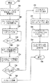
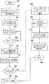
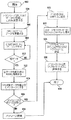
本発明の別の形態によれば、車両の通信ネットワークに動作上結合されている車両制御コンピュータとリモート・コンピュータとの間の通信を可能にするアダプタを提供する。この方法は、第1インターフェースを介してデータを受信するステップであって、第1インターフェースが車両の通信ネットワークに動作上結合されている、ステップと、データを第2インターフェースを介して送信するステップであって、第2インターフェースが、USBデバイス・ポートおよびUSBホスト・ポートを有するユニバーサル・シリアル・バス・コントローラを含み、第2インターフェースが、USBデバイス・ポートおよびUSBホスト・ポートを介してコンピュータに動作上結合するように構成されている、ステップとから成る。車両制御コンピュータによって第1データを送信し、リモート・コンピュータによって第1データを受信する。 In accordance with another aspect of the invention, an adapter is provided that enables communication between a vehicle control computer and a remote computer that are operatively coupled to a vehicle communication network. The method includes receiving data via a first interface, wherein the first interface is operatively coupled to a vehicle communication network and transmitting the data via a second interface. The second interface includes a universal serial bus controller having a USB device port and a USB host port, and the second interface is operatively connected to the computer via the USB device port and the USB host port. The steps are configured to be coupled. The first data is transmitted by the vehicle control computer, and the first data is received by the remote computer.
一例として、本発明のこの形態によれば、データはネットワーク・メッセージであり、このネットワーク・メッセージは宛先アドレスを含む。
別の例として、本発明のこの形態によれば、送信するステップは、ネットワーク・メッセージが第2インターフェースに宛てられているか否か判定し、ネットワーク・メッセージが第2インターフェースに宛てられている場合にのみ、ネットワーク・メッセージを第2インターフェースを介して送信することから成る。
As an example, according to this aspect of the invention, the data is a network message, which includes a destination address.
As another example, according to this aspect of the invention, the transmitting step determines whether the network message is destined for the second interface and if the network message is destined for the second interface. Only consists of sending a network message over the second interface.
別の例として、本発明のこの形態によれば、ネットワーク・メッセージが第2インターフェースに宛てられているか否かの判定は、アドレスを読み取り、それを既存のアドレスと比較することから成る。 As another example, according to this aspect of the invention, determining whether a network message is destined for a second interface consists of reading an address and comparing it to an existing address.
あるいは、本発明のこの形態によれば、一例として、送信するステップは、ネットワーク・メッセージの宛先アドレスには無関係に、第2インターフェースを介してネットワーク・メッセージを送信することから成る。 Alternatively, according to this aspect of the invention, by way of example, the step of sending comprises sending the network message via the second interface regardless of the destination address of the network message.
本発明の別の形態によれば、車両通信ネットワークに動作上結合されている車両制御コンピュータとリモート・コンピュータとの間の通信を可能にするアダプタを提供する。このアダプタは、車両通信ネットワークに動作上結合するように構成されている第1インターフェースと、USBオンザゴー・ポートを含む第2インターフェースとを備えている。第2インターフェースは、USBオンザゴー・ポートを介してリモート・コンピュータに動作上結合するように構成されている。車両制御コンピュータおよびリモート・コンピュータは、車両通信ネットワークと第1および第2インターフェースとを介して通信する。 In accordance with another aspect of the invention, an adapter is provided that enables communication between a vehicle control computer and a remote computer that are operatively coupled to a vehicle communication network. The adapter includes a first interface configured to operably couple to a vehicle communication network and a second interface including a USB on-the-go port. The second interface is configured to operably couple to a remote computer via a USB on-the-go port. The vehicle control computer and the remote computer communicate via the vehicle communication network and the first and second interfaces.
一例として、本発明のこの形態によれば、リモート・コンピュータは、USBデバイス・ポートを有するパーソナル・ディジタル・アシスタントであり、パーソナル・ディジタル・アシスタントのUSBデバイス・ポートは、アダプタのUSBオンザゴー・ポートに動作上結合されている。 As an example, according to this aspect of the invention, the remote computer is a personal digital assistant having a USB device port, and the USB device port of the personal digital assistant is the USB on-the-go port of the adapter. Coupled in operation.
別の例として、本発明のこの形態によれば、パーソナル・ディジタル・アシスタントは、サービス・ツール・ソフトウェアを備えている。
あるいは、本発明のこの形態によれば、一例として、リモート・コンピュータは、USBホスト・ポートを有するパーソナル・コンピュータであり、パーソナル・コンピュータのUSBホスト・ポートは、ユニバーサル・シリアル・バス・コントローラのUSBオンザゴー・ポートに動作上結合されている。
As another example, according to this aspect of the invention, the personal digital assistant comprises service tool software.
Alternatively, according to this aspect of the invention, by way of example, the remote computer is a personal computer having a USB host port, and the USB host port of the personal computer is a USB of a universal serial bus controller. Operatively coupled to the on-the-go port.
あるいは、本発明のこの形態によれば、一例として、パーソナル・コンピュータは、車両診断ソフトウェアを備えている。
あるいは、本発明のこの形態によれば、一例として、車両通信ネットワークは、J1939ネットワーク・セグメントを備えており、アダプタの第1インターフェースは、J1939ネットワーク・セグメントに動作上結合されている。
Alternatively, according to this aspect of the invention, as an example, the personal computer comprises vehicle diagnostic software.
Alternatively, according to this aspect of the invention, by way of example, the vehicle communication network comprises a J1939 network segment, and the first interface of the adapter is operatively coupled to the J1939 network segment.
別の例として、本発明のこの形態によれば、J1939ネットワーク・セグメントを介して伝達するメッセージを、第2インターフェースによって利用可能とする。
別の例として、本発明のこの形態によれば、リモート・コンピュータは、USBデバイス・ポートを有するパーソナル・ディジタル・アシスタントであり、パーソナル・ディジタル・アシスタントのUSBデバイス・ポートは、アダプタのUSBオンザゴー・ポートに動作上結合されており、J1939ネットワーク・セグメントを介して伝達するメッセージを、更にパーソナル・ディジタル・アシスタントに伝達する。
As another example, according to this aspect of the invention, messages communicated over the J1939 network segment are made available by the second interface.
As another example, according to this aspect of the invention, the remote computer is a personal digital assistant having a USB device port, and the USB device port of the personal digital assistant is a USB on-the-go adapter of the adapter. Messages that are operably coupled to the port and communicate through the J1939 network segment are further communicated to the personal digital assistant.
あるいは、本発明のこの形態によれば、一例として、リモート・コンピュータは、USBホスト・ポートを有するパーソナル・コンピュータであり、パーソナル・コンピュータのUSBホスト・ポートは、アダプタのUSBオンザゴー・ポートに動作上結合されており、J1939ネットワーク・セグメントを介して伝達するメッセージを、更にパーソナル・コンピュータに伝達する。 Alternatively, according to this aspect of the invention, by way of example, the remote computer is a personal computer having a USB host port, and the USB host port of the personal computer is operatively connected to the USB on-the-go port of the adapter. Messages that are coupled and communicated through the J1939 network segment are further communicated to the personal computer.
あるいは、本発明のこの形態によれば、一例として、車両通信ネットワークは、J1587ネットワーク・セグメントを備えており、アダプタの第1インターフェースは、J1587ネットワーク・セグメントに動作上結合されている。 Alternatively, according to this aspect of the invention, by way of example, the vehicle communication network comprises a J1587 network segment, and the first interface of the adapter is operatively coupled to the J1587 network segment.
別の例として、本発明のこの形態によれば、J1587ネットワーク・セグメントを介して伝達するメッセージを、第2インターフェースによって利用可能とする。
別の例として、本発明のこの形態によれば、リモート・コンピュータは、USBデバイス・ポートを有するパーソナル・ディジタル・アシスタントであり、パーソナル・ディジタル・アシスタントのUSBデバイス・ポートは、アダプタのUSBオンザゴー・ポートに動作上結合されており、J1587ネットワーク・セグメントを介して伝達するメッセージを、更に、パーソナル・ディジタル・アシスタントに伝達する。
As another example, according to this aspect of the invention, messages communicated over the J1587 network segment are made available by the second interface.
As another example, according to this aspect of the invention, the remote computer is a personal digital assistant having a USB device port, and the USB device port of the personal digital assistant is a USB on-the-go adapter of the adapter. Messages that are operably coupled to the port and communicated through the J1587 network segment are further communicated to the personal digital assistant.
あるいは、本発明のこの形態によれば、一例として、リモート・コンピュータは、USBホスト・ポートを有するパーソナル・コンピュータであり、パーソナル・コンピュータのUSBホスト・ポートは、アダプタのUSBオンザゴー・ポートに動作上結合されており、J1587ネットワーク・セグメントを介して伝達するメッセージを、更に、パーソナル・コンピュータに伝達する。 Alternatively, according to this aspect of the invention, as an example, the remote computer is a personal computer having a USB host port, and the USB host port of the personal computer is operatively connected to the USB on-the-go port of the adapter. Messages that are coupled and communicated through the J1587 network segment are further communicated to the personal computer.
あるいは、本発明のこの形態によれば、一例として、アダプタは、更に、第2リモート・コンピュータに動作上結合するように構成された第3インターフェースを備えており、第3インターフェースはRS−232シリアル・ポートを備えている。 Alternatively, according to this aspect of the invention, by way of example, the adapter further comprises a third interface configured to operably couple to the second remote computer, wherein the third interface is an RS-232 serial. -It has a port.
別の例として、本発明のこの形態によれば、第2リモート・コンピュータは、RS−232シリアル・ポートを有するパーソナル・ディジタル・アシスタントであり、パーソナル・ディジタル・アシスタントのRS−232シリアル・ポートは、アダプタのRS−232シリアル・ポートに動作上結合されている。 As another example, according to this aspect of the invention, the second remote computer is a personal digital assistant having an RS-232 serial port, and the RS-232 serial port of the personal digital assistant is , And is operably coupled to the RS-232 serial port of the adapter.
別の例として、本発明のこの形態によれば、パーソナル・ディジタル・アシスタントは、サービス・ツール・ソフトウェアを備えている、アダプタ。
別の例として、本発明のこの形態によれば、第2リモート・コンピュータは、RS−232シリアル・ポートを有するパーソナル・コンピュータであり、パーソナル・コンピュータのRS−232シリアル・ポートは、アダプタのRS−232シリアル・ポートに動作上結合されている。
As another example, according to this aspect of the invention, a personal digital assistant is provided with service tool software.
As another example, according to this aspect of the invention, the second remote computer is a personal computer having an RS-232 serial port, and the RS-232 serial port of the personal computer is the RS of the adapter. -232 is operably coupled to the serial port.
別の例として、本発明のこの形態によれば、パーソナル・コンピュータは、車両診断ソフトウェアを備えている。
本発明の別の形態によれば、車両の制御コンピュータとリモート・コンピュータとの間の通信を可能にするアダプタを提供する。このアダプタは、車両のJ1939ネットワーク・セグメントに動作上結合するように構成されている第1インターフェースと、車両のJ1587ネットワーク・セグメントに動作上結合するように構成されている第2インターフェースと、USBオンザゴー・ポートを含む第3インターフェースであって、USBオンザゴー・ポートを介してリモート・コンピュータに動作上結合するように構成されている、第3インターフェースとを備えている。車両の各制御コンピュータおよびリモート・コンピュータは、J1939ネットワークと第1および第3インターフェース、ならびにJ1587ネットワークと第2および第3インターフェースの一方を介して通信する。
As another example, according to this aspect of the invention, the personal computer comprises vehicle diagnostic software.
According to another aspect of the invention, an adapter is provided that enables communication between a vehicle control computer and a remote computer. The adapter includes a first interface configured to operably couple to the vehicle's J1939 network segment, a second interface configured to operably couple to the vehicle's J1587 network segment, and USB on-the-go. A third interface including a port, the third interface configured to be operatively coupled to a remote computer via a USB on-the-go port; Each control computer and remote computer of the vehicle communicates via one of the J1939 network and the first and third interfaces, and the J1587 network and the second and third interfaces.
別の例として、本発明のこの形態によれば、リモート・コンピュータは、USBオンザゴー・ポートを有するディジタル・パーソナル・アシスタントまたはパーソナル・コンピュータであり、リモート・コンピュータのUSBオンザゴー・ポートは、アダプタのUSBオンザゴー・ポートに動作上結合されている。 As another example, according to this aspect of the invention, the remote computer is a digital personal assistant or personal computer with a USB on-the-go port, and the USB on-the-go port of the remote computer is the USB of the adapter. Operatively coupled to the on-the-go port.
別の例として、本発明のこの形態によれば、リモート・コンピュータは、USBデバイス・ポートを有するパーソナル・ディジタル・アシスタントであり、パーソナル・ディジタル・アシスタントのUSBデバイス・ポートは、アダプタのUSBオンザゴー・ポートに動作上結合されている。 As another example, according to this aspect of the invention, the remote computer is a personal digital assistant having a USB device port, and the USB device port of the personal digital assistant is a USB on-the-go adapter of the adapter. Operationally coupled to the port.
あるいは、本発明のこの形態によれば、一例として、リモート・コンピュータは、USBホスト・ポートを有するパーソナル・コンピュータであり、パーソナル・コンピュータのUSBホスト・ポートは、アダプタのUSBオンザゴー・ポートに動作上結合されている。 Alternatively, according to this aspect of the invention, as an example, the remote computer is a personal computer having a USB host port, and the USB host port of the personal computer is operatively connected to the USB on-the-go port of the adapter. Are combined.
別の例として、本発明のこの形態によれば、リモート・コンピュータは、サービス・ツール・ソフトウェアを備えている。
別の例として、本発明のこの形態によれば、リモート・コンピュータは、車両診断ソフトウェアを備えている。
As another example, according to this aspect of the invention, the remote computer comprises service tool software.
As another example, according to this aspect of the invention, the remote computer comprises vehicle diagnostic software.
あるいは、本発明のこの形態によれば、一例として、アダプタは、更に、第2リモート・コンピュータに動作上結合するように構成されている第4インターフェースを備えており、第4インターフェースはRS−232シリアル・ポートを備えている。 Alternatively, according to this aspect of the invention, by way of example, the adapter further comprises a fourth interface configured to operably couple to the second remote computer, wherein the fourth interface is RS-232. Has a serial port.
別の例として、本発明のこの形態によれば、第2リモート・コンピュータは、RS−232シリアル・ポートを有するパーソナル・ディジタル・アシスタントであり、パーソナル・ディジタル・アシスタントのRS−232シリアル・ポートは、アダプタのRS−232シリアル・ポートに動作上結合されている。 As another example, according to this aspect of the invention, the second remote computer is a personal digital assistant having an RS-232 serial port, and the RS-232 serial port of the personal digital assistant is , And is operably coupled to the RS-232 serial port of the adapter.
あるいは、本発明のこの形態によれば、一例として、第2リモート・コンピュータは、RS−232シリアル・ポートを有するパーソナル・コンピュータであり、パーソナル・コンピュータのRS−232シリアル・ポートは、アダプタのRS−232シリアル・ポートに動作上結合されている。 Alternatively, according to this aspect of the invention, by way of example, the second remote computer is a personal computer having an RS-232 serial port, and the RS-232 serial port of the personal computer is the RS of the adapter. -232 is operably coupled to the serial port.
あるいは、本発明のこの形態によれば、一例として、第2リモート・コンピュータは、サービス・ツール・ソフトウェアを備えている。
あるいは、本発明のこの形態によれば、一例として、第2リモート・コンピュータは、車両診断ソフトウェアを備えている。
Alternatively, according to this aspect of the invention, by way of example, the second remote computer comprises service tool software.
Alternatively, according to this aspect of the invention, as an example, the second remote computer comprises vehicle diagnostic software.
あるいは、本発明のこの形態によれば、一例として、リモート・コンピュータが第2リモート・コンピュータである、アダプタ。
本発明は、更に、1つ以上の以下の特徴またはその組み合わせを備えることもできる。自動車に搭載され第1プロトコルによる通信に対し構成されている通信ネットワークと、第2プロトコルによる通信に対し構成されているリモート・システムとの間の通信ブリッジは、通信ネットワークに結合するように構成されている第1インターフェースと、リモート・システムに結合するように構成されている第2インターフェースと、命令サイクル当たり多数の動作を処理するように構成されているディジタル信号プロセッサ(DSP)とを備えることができる。DSPは、第1プロトコルにしたがって構成された情報を、通信ネットワークから第1インターフェースを介して受信し、通信ネットワークから受信した、第1プロトコルにしたがって構成された情報を、第2プロトコルに変換し、第2プロトコルに変換した情報を、第2インターフェースを介してリモート・システムに送信し、第2プロトコルにしたがって構成された情報をリモート・システムから第2インターフェースを介して受信する。更に、DSPは、リモート・システムから受信した、第2プロトコルにしたがって構成された情報を第1プロトコルに変換し、第1プロトコルに変換した情報を、第1インターフェースを介して通信ネットワークに送信する。
Alternatively, according to this aspect of the invention, by way of example, an adapter wherein the remote computer is a second remote computer.
The present invention may further comprise one or more of the following features or combinations thereof. A communication bridge between a communication network installed in a vehicle and configured for communication according to the first protocol and a remote system configured for communication according to the second protocol is configured to couple to the communication network. A first interface configured to couple to the remote system, and a digital signal processor (DSP) configured to process a number of operations per instruction cycle. it can. The DSP receives information configured according to the first protocol from the communication network via the first interface, converts the information configured according to the first protocol received from the communication network into the second protocol, Information converted to the second protocol is transmitted to the remote system via the second interface, and information configured according to the second protocol is received from the remote system via the second interface. Further, the DSP converts the information configured according to the second protocol received from the remote system into the first protocol, and transmits the information converted into the first protocol to the communication network via the first interface.
通信は、更に、自動車に搭載され、通信ネットワークと通信状態に接続されている制御コンピュータを含み、制御コンピュータは、第1プロトコルにしたがって構成された情報を通信ネットワークに供給する。 The communication further includes a control computer mounted on the vehicle and connected in communication with the communication network, the control computer supplying information configured according to the first protocol to the communication network.
自動車に搭載した通信ネットワークは、自動車技師協会(SAE)J1708ハードウェア・ネットワークとすることができ、第1プロトコルは、SAE J1708ハードウェア・ネットワークを通じて通信するように構成されているSAE J1587通信プロトコルである。第1インターフェースは、SAE J1708ハードウェア・ネットワークに結合するように構成されている第1トランシーバであり、第1トランシーバは、SAE J1587通信プロトコルにしたがって構成された情報を送信し、かつSAE J1708ハードウェア・ネットワークから受信するように動作可能である。通信ブリッジは、更に、自動車に搭載され、SAE J1708ハードウェア・ネットワークと通信状態に接続されている制御コンピュータを含み、制御コンピュータは、SAE J1587プロトコルにしたがって構成された情報を、SAE J1708ハードウェア・ネットワークに供給する。この実施形態では、第2プロトコルは、RS−232通信プロトコルとすることができ、第2インターフェースは、リモート・システムのRS−232通信ポートに結合するように構成されている第2トランシーバとすることができ、第2トランシーバは、RS−232通信プロトコルにしたがって構成された情報を送信し、リモート・システムから受信するように動作可能である。あるいは、第2プロトコルは、ユニバーサル・シリアル・バス(USB)通信プロトコルとすることができ、第2インターフェースは、リモート・システムの第2USBインターフェース・ポートに結合するように構成されている第1USBインターフェース・ポートを有するUSBコントローラであり、USBコントローラは、USB通信プロトコルにしたがって構成された情報を送信し、かつリモート・システムから受信するように動作可能である。リモート・システムは、USBデバイスとして構成することができ、第1USBインターフェース・ポートは、USBホスト・ポート、またはホストUSBポートとして動作可能なオンザゴーUSBポートとして構成することができる。あるいは、リモート・システムは、USBホストとして構成することができ、第1USBインターフェース・ポートは、USBデバイス・ポートまたはデバイスUSBポートとして動作可能なオンザゴーUSBポートとして構成することができる。いずれの場合でも、リモート・システムは、パーソナル・コンピュータ、ハンドヘルド・パーソナル・ディジタル・アシスタント、あるいは、その他のリモート・システムまたはユニットである。 The communication network installed in the vehicle can be the Automotive Engineers Association (SAE) J1708 hardware network, and the first protocol is the SAE J1588 communication protocol configured to communicate through the SAE J1708 hardware network. is there. The first interface is a first transceiver configured to couple to the SAE J1708 hardware network, the first transceiver transmits information configured in accordance with the SAE J1587 communication protocol, and the SAE J1708 hardware It is operable to receive from the network. The communication bridge further includes a control computer mounted on the vehicle and connected in communication with the SAE J1708 hardware network, the control computer receiving information configured according to the SAE J1587 protocol. Supply to the network. In this embodiment, the second protocol can be an RS-232 communication protocol and the second interface can be a second transceiver configured to couple to an RS-232 communication port of a remote system. And the second transceiver is operable to transmit and receive information configured in accordance with the RS-232 communication protocol from a remote system. Alternatively, the second protocol can be a universal serial bus (USB) communication protocol, and the second interface is configured to couple to a second USB interface port of the remote system. A USB controller having a port, the USB controller is operable to transmit information received according to a USB communication protocol and to receive from a remote system. The remote system can be configured as a USB device, and the first USB interface port can be configured as a USB host port or an on-the-go USB port operable as a host USB port. Alternatively, the remote system can be configured as a USB host and the first USB interface port can be configured as an on-the-go USB port operable as a USB device port or device USB port. In any case, the remote system is a personal computer, handheld personal digital assistant, or other remote system or unit.
あるいは、自動車に搭載した通信ネットワークは、自動車技師協会(SAE)J1939ハードウェア・ネットワークであってもよく、第1プロトコルは、SAE J1939ハードウェア・ネットワーク上でも通信に対し構成されているSAE J1939通信プロトコルである。第1インターフェースは、SAE J1939ハードウェア・ネットワークに結合するように構成されている第1トランシーバであり、第1トランシーバは、SAE J1939通信プロトコルにしたがって構成された情報をSAE J1939ハードウェア・ネットワークに送信し、かつSAE J1939ハードウェア・ネットワークから受信するように動作可能である。通信ブリッジは、更に、自動車に搭載され、SAE J1939ハードウェア・ネットワークと通信状態に接続されている制御コンピュータを含むことができ、制御コンピュータは、SAE J1939プロトコルにしたがって構成された情報を、SAE J1939ハードウェア・ネットワークに供給する。この実施形態では、第2インターフェースは、リモート・システムのRS−232通信ポートに結合するように構成されている第2トランシーバであり、第2トランシーバは、RS−232通信プロトコルにしたがって構成された情報をリモート・システムに送信し、かつリモート・システムから受信するように動作可能である。あるいは、第2プロトコルは、ユニバーサル・シリアル・バス(USB)通信プロトコルであってもよく、第2インターフェースは、リモート・システムの第2USBインターフェース・ポートに結合するように構成されている第1USBインターフェース・ポートを有するUSBコントローラとすることができ、USBコントローラは、USB通信プロトコルにしたがって構成された情報を、リモート・システムに送信し、かつリモート・システムから受信するように動作可能である。リモート・システムは、USBデバイスとして構成することができ、第1USBインターフェース・ポートは、USBホスト・ポート、またはホストUSBポートとして動作可能なオンザゴーUSBポートとして構成されている。あるいは、リモート・システムは、USBポートとして構成することもでき、第1USBインターフェース・ポートは、USBデバイス・ポート、またはデバイスUSBポートとして動作可能なオンザゴーUSBポートとして構成されている。いずれの場合でも、リモート、システムは、パーソナル・コンピュータ、ハンドヘルド・パーソナル・ディジタル・アシスタント・デバイス、あるいはその他のリモート・システムまたはユニットとすることができる。 Alternatively, the communication network onboard the vehicle may be the Automobile Engineers Association (SAE) J1939 hardware network, and the first protocol is SAE J1939 communication configured for communication on the SAE J1939 hardware network. Protocol. The first interface is a first transceiver configured to couple to the SAE J1939 hardware network, and the first transceiver transmits information configured according to the SAE J1939 communication protocol to the SAE J1939 hardware network. And is operable to receive from the SAE J1939 hardware network. The communication bridge may further include a control computer mounted on the vehicle and connected in communication with the SAE J1939 hardware network, the control computer displaying information configured in accordance with the SAE J1939 protocol. Supply to hardware network. In this embodiment, the second interface is a second transceiver configured to couple to the RS-232 communication port of the remote system, and the second transceiver is information configured in accordance with the RS-232 communication protocol. To the remote system and to receive from the remote system. Alternatively, the second protocol may be a universal serial bus (USB) communication protocol, and the second interface is configured to couple to a second USB interface port of the remote system. The USB controller can have a port, and the USB controller is operable to send and receive information configured according to the USB communication protocol to and from the remote system. The remote system can be configured as a USB device, and the first USB interface port is configured as a USB host port or an on-the-go USB port operable as a host USB port. Alternatively, the remote system can be configured as a USB port, and the first USB interface port is configured as a USB device port or an on-the-go USB port operable as a device USB port. In any case, the remote system can be a personal computer, a handheld personal digital assistant device, or other remote system or unit.
更に、通信ブリッジは、第1電源電圧を第1トランシーバに供給するように構成されている電源を含むことができる。
通信ブリッジは、更に、1つ以上の電源電圧を受け、1つ以上の電源電圧の内1つを選択的に電源に入力電圧として供給する電源選択回路を含むことができ、電源は入力電圧の関数として、第1電源電圧を生成する。電源は、更に、第1電源電圧を、入力電圧の関数として、DSPおよび第2トランシーバに供給するように構成されており、第2電源電圧は第1電源電圧よりも低い。DSPはプログラマブル・フラッシュ・メモリを含むことができ、電源は、更に、フラッシュ・メモリ・プログラミング電圧を、入力電圧の関数として、DSPに供給するように構成することができる。
Further, the communication bridge can include a power source configured to provide a first power supply voltage to the first transceiver.
The communication bridge may further include a power selection circuit that receives one or more power supply voltages and selectively supplies one of the one or more power supply voltages as an input voltage to the power supply. A first power supply voltage is generated as a function. The power supply is further configured to supply a first power supply voltage to the DSP and the second transceiver as a function of the input voltage, the second power supply voltage being lower than the first power supply voltage. The DSP can include a programmable flash memory, and the power supply can be further configured to provide a flash memory programming voltage to the DSP as a function of the input voltage.
1つ以上の電源電圧は、外部電圧源を介して、通信ブリッジに供給されるDC電圧を含むことができる。
更に、通信ブリッジは、バッテリ電圧を供給する少なくとも1つのバッテリを含むことができ、1つ以上の電源電圧は、バッテリによって供給されるバッテリ電圧を含むこともできる。
The one or more power supply voltages can include a DC voltage supplied to the communication bridge via an external voltage source.
Further, the communication bridge can include at least one battery that provides a battery voltage, and the one or more power supply voltages can also include a battery voltage supplied by the battery.
更に、通信ブリッジは、電源が生成した充電電圧を受け、充電電圧を通信ブリッジ外部に供給する、外部バッテリ充電回路を含むことができる。リモート・システムは、パーソナル・ディジタル・アシスタント(PDA)デバイスとすることができ、外部バッテリ充電回路が生成する充電電圧をPDAに供給すると、それに搭載した1つ以上のバッテリを充電することができる。DSPは、電源が生成する充電電圧を監視する電圧測定入力を含むことができ、DSPは、充電電圧を測定し、得られた測定電圧値を、第2トランシーバが送信する診断メッセージを介して、PDAに供給する。 Further, the communication bridge can include an external battery charging circuit that receives the charging voltage generated by the power source and supplies the charging voltage to the outside of the communication bridge. The remote system can be a personal digital assistant (PDA) device, which can charge one or more batteries mounted on the PDA when a charging voltage generated by an external battery charging circuit is supplied to the PDA. The DSP can include a voltage measurement input that monitors the charging voltage generated by the power supply, the DSP measures the charging voltage, and the resulting measured voltage value is transmitted via a diagnostic message transmitted by the second transceiver. Supply to PDA.
DSPは、外部電圧源が供給するDC電圧を監視する電圧測定入力を含むことができる。
更に、通信ブリッジは、電源ステータス・インディケータと、DSPの制御出力に接続されている制御入力と、電源ステータス・インディケータに接続されているドライバ出力とを有するドライバ回路とを含むことができ、DSPは、ドライバ回路を介して電源ステータス・インディケータを制御し、DC電圧の測定値の視覚実施を与えるように動作可能である。電源ステータス・インディケータは、電源ステータス発光ダイオード(LED)とすることができ、DSPは、ドライバ回路を介して、電源ステータスLEDを制御し、DC電圧の測定値が既定の電圧範囲内にあるときはいつでも電源ステータスLEDを照明し、DC電圧の測定値が既定の電圧範囲未満の閾値電圧よりも低い場合はいつでも、オフ状態に切り換えるようにする。DSPは、更に、ドライバ回路を介して、電源ステータスLEDを制御し、DC電圧の測定値が既定の電圧範囲外にあるときはいつでも、電源ステータスLEDが既定の切換レートでオンおよびオフに切り替わるように動作可能とすることもできる。
The DSP can include a voltage measurement input that monitors the DC voltage supplied by the external voltage source.
In addition, the communication bridge can include a driver circuit having a power status indicator, a control input connected to the control output of the DSP, and a driver output connected to the power status indicator. The power status indicator is controlled via the driver circuit and is operable to provide a visual implementation of the DC voltage measurement. The power status indicator can be a power status light emitting diode (LED), and the DSP controls the power status LED via a driver circuit when the DC voltage measurement is within a predetermined voltage range. At any time, the power status LED is illuminated and switched to the off state whenever the DC voltage measurement is below a threshold voltage below a predetermined voltage range. The DSP further controls the power status LED via a driver circuit so that the power status LED switches on and off at a predetermined switching rate whenever the DC voltage measurement is outside the predetermined voltage range. It can also be operable.
更に、通信ブリッジは、別のステータス・インディケータと、DSPの制御出力に接続されている制御入力と、ステータス・インディケータに接続されているドライバ出力とを有するドライバ回路とを含むことができ、DSPは、ドライバ回路を介して、ステータス・インディケータを制御し、通信ネットワークとリモート・システムとの間で、ステータスの視覚指示の情報転送を行うように動作可能である。 Further, the communication bridge can include a driver circuit having another status indicator, a control input connected to the control output of the DSP, and a driver output connected to the status indicator, the DSP It is operable to control the status indicator via the driver circuit and transfer information of status visual indication between the communication network and the remote system.
自動車に搭載した通信ネットワークは、自動車技師協会(SAE) J1708ハードウェア・ネットワークとすることができ、第1プロトコルは、SAE J1708ハードウェア・ネットワーク上での通信に対し構成されたSAE J1587通信プロトコルであり、第1トランシーバは、SAE J1587通信プロトコルにしたがって構成された情報をSAE J1708ハードウェア・ネットワークに送信し、かつSAE J1708ハードウェア・ネットワークから受信するように動作可能である。ステータス・インディケータは、J1587/J1708通信ステータス発光ダイオード(LED)とすることができ、DSPは、J1708ハードウェア・ネットワークが非応答状態にあり、かつDSPが第1トランシーバを介してデータを送信している場合、J1587/J1708通信ステータスLEDを第1既定切換レートでオンおよびオフに切り換え、J1708ハードウェア・ネットワークが応答状態にあり、DSPが、トランシーバを介して、情報をJ1708ハードウェア・ネットワークに送信し、かつJ1708ハードウェア・ネットワークから受信している場合、第1切換レートよりも速い第2既定切換レートでJ1587/J1708通信ステータスLEDを切り換え、DSPが、第1トランシーバを介して、情報をJ1708ハードウェア・ネットワークに送信しておらず、J1708ハードウェア・ネットワークから受信もしていない場合はいつでも、J1587/J1708通信ステータスLEDをオフ状態に保持する。 The communication network installed in the vehicle can be the Automobile Engineers Association (SAE) J1708 hardware network, and the first protocol is the SAE J1587 communication protocol configured for communication on the SAE J1708 hardware network. Yes, the first transceiver is operable to send information received in accordance with the SAE J1587 communication protocol to the SAE J1708 hardware network and to receive from the SAE J1708 hardware network. The status indicator can be a J1587 / J1708 communication status light emitting diode (LED), and the DSP can send data through the first transceiver when the J1708 hardware network is non-responsive. Switch the J1587 / J1708 communication status LED on and off at the first default switching rate, the J1708 hardware network is in a responsive state, and the DSP sends information to the J1708 hardware network via the transceiver And if it is receiving from the J1708 hardware network, it switches the J1587 / J1708 communication status LED at a second default switching rate that is faster than the first switching rate, and the DSP passes the information through the first transceiver. 1708 not transmitting to the hardware network, whenever not be received from the J1708 hardware network, holds the J1587 / J1708 communications status LED off.
あるいは、自動車に搭載した通信ネットワークは、自動車技師協会(SAE) J1939ハードウェア・ネットワークとしてもよく、または含んでもよく、第1プロトコルは、SAE J1939ハードウェア・ネットワーク上での通信に対し構成されたSAE J1939通信プロトコルであり、第1トランシーバは、SAE J1939通信プロトコルにしたがって構成された情報を、SAE J1939ハードウェア・ネットワークに送信し、かつSAE J1939ハードウェア・ネットワークから受信するように動作可能なコントローラ・エリア・ネットワーク(CAN)トランシーバである。この場合、ステータス・インディケータは、J1939通信ステータス発光ダイオード(LED)とすることができ、DSPは、J1939ハードウェア・ネットワークが非応答状態にあり、かつDSPが第1トランシーバを介してデータを送信している場合、J1939通信ステータスLEDを第1既定切換レートでオンおよびオフに切り換え、J1939ハードウェア・ネットワークが応答状態にあり、DSPが、CANトランシーバを介して、情報をJ1939ハードウェア・ネットワークに送信し、かつJ1939ハードウェア・ネットワークから受信している場合、第1切換レートよりも速い第2既定切換レートでJ1939通信ステータスLEDを切り換え、DSPが、CANトランシーバを介して、情報をJ1939ハードウェア・ネットワークに送信しておらず、J1939ハードウェア・ネットワークから受信もしていない場合はいつでも、J1939通信ステータスLEDをオフ状態に保持する。 Alternatively, the onboard communications network may be or include the Automobile Engineers Association (SAE) J1939 hardware network, and the first protocol is configured for communication over the SAE J1939 hardware network. The SAE J1939 communication protocol, wherein the first transceiver is operable to send information to the SAE J1939 hardware network and receive information from the SAE J1939 hardware network, configured according to the SAE J1939 communication protocol. An area network (CAN) transceiver. In this case, the status indicator can be a J1939 Communication Status Light Emitting Diode (LED), the DSP is not responding to the J1939 hardware network, and the DSP transmits data through the first transceiver. Switch the J1939 communication status LED on and off at the first default switching rate, the J1939 hardware network is in a responsive state, and the DSP sends information to the J1939 hardware network via the CAN transceiver And if it is receiving from the J1939 hardware network, it switches the J1939 communication status LED at a second default switching rate that is faster than the first switching rate, and the DSP passes the information through the CAN transceiver to the J1939 hardware. Not transmitting the A network, whenever not be received from the J1939 hardware network, holds the J1939 communication status LED off.
第2プロトコルは、RS−232通信プロトコルとすることができ、第2トランシーバは、リモート・システムのRS−232通信ポートに結合するように構成されており、第2トランシーバは、RS−232通信プロトコルにしたがって構成された情報を、リモート・システムに送信し、かつリモート・システムから受信するように動作可能である。この場合、ステータス・インディケータは、RS−232通信ステータス発光ダイオード(LED)とすることができ、DSPは、リモート・システムの第2RS−232通信ポートが非応答状態にあり、かつDSPが第2トランシーバを介してデータを送信している場合、RS−232通信ステータスLEDを第1既定切換レートでオンおよびオフに切り換え、リモート・システムの第2RS−232通信ポートが応答状態にあり、DSPが、第2トランシーバを介して、情報をリモート・システムに送信し、かつリモート・システムから受信している場合、第1切換レートよりも速い第2既定切換レートでRS−232通信ステータスLEDを切り換え、DSPが、第2トランシーバを介して、情報をリモート・システムに送信しておらず、リモート・システムから受信もしていない場合はいつでも、RS−232通信ステータスLEDをオフ状態に保持する。 The second protocol can be an RS-232 communication protocol, the second transceiver is configured to couple to an RS-232 communication port of a remote system, and the second transceiver is an RS-232 communication protocol. Is configured to transmit to and receive from the remote system. In this case, the status indicator may be an RS-232 communication status light emitting diode (LED), the DSP is in a non-responsive state at the second RS-232 communication port of the remote system, and the DSP is at the second transceiver. The RS-232 communication status LED is turned on and off at the first default switching rate, the second RS-232 communication port of the remote system is in the responding state, and the DSP If the information is sent to and received from the remote system via the two transceivers, the RS-232 communication status LED is switched at a second default switching rate that is faster than the first switching rate, and the DSP The information is sent to the remote system via the second transceiver. , Whenever not be received from a remote system to hold the RS-232 communication status LED off.
第2プロトコルは、ユニバーサル・シリアル・バス(USB)通信プロトコルとすることができ、第1トランシーバは、リモート・システムの第2USBポートに結合するように構成されている第1USBポートを有するUSBコントローラおよびトランシーバ回路であり、USBコントローラおよびトランシーバ回路は、USB通信プロトコルにしたがって構成された情報を、リモート・システムに送信し、かつリモート・システムから受信するように動作可能である。この場合、ステータス・インディケータは、USB通信ステータス発光ダイオード(LED)とすることができ、DSPは、リモート・システムの第2USBポートが非応答状態にあり、DSPがUSBコントローラおよびトランシーバ回路を介してデータを送信している場合、USB通信ステータスLEDを第1既定切換レートでオンおよびオフに切り換え、リモート・システムの第2USBが応答状態にあり、DSPがUSBコントローラおよびトランシーバ回路を介して、情報をリモート・システムに送信し、かつリモート・システムから受信している場合、USB通信ステータスLEDを、第1切換レートよりも速い第2既定切換レートでオンおよびオフに切り換え、DSPがUSBコントローラおよびトランシーバ回路を介して、情報をリモート・システムに送信しておらず、かつリモート・システムから受信してもいない場合、USB通信ステータスLEDをオフ状態に保持する。 The second protocol may be a universal serial bus (USB) communication protocol, the first transceiver having a first USB port configured to couple to a second USB port of the remote system and A transceiver circuit, wherein the USB controller and transceiver circuit are operable to send information to and receive information from a remote system configured in accordance with a USB communication protocol. In this case, the status indicator can be a USB communication status light emitting diode (LED), and the DSP is in a state where the second USB port of the remote system is not responding, and the DSP receives data via the USB controller and transceiver circuit. The USB communication status LED is switched on and off at the first predetermined switching rate, the second USB of the remote system is in the responding state, and the DSP remotely transmits information via the USB controller and transceiver circuit. When transmitting to the system and receiving from the remote system, the USB communication status LED is switched on and off at a second default switching rate that is faster than the first switching rate, and the DSP switches the USB controller and transceiver circuit Through, Not transmitting broadcast to the remote system, and if not be received from the remote system to hold the USB communication status LED off.
自動車に搭載した少なくとも1つの通信ネットワークとリモート・システムとの間で情報を伝達する方法において、少なくとも1つの通信ネットワークは第1プロトコルによる通信に対し構成されており、リモート・システムは第3プロトコルによる通信に対し構成されており、この方法は、少なくとも1つの通信ネットワークに結合されている第1インターフェースを介して、第1プロトコルにしたがって構成されている少なくとも1つの通信ネットワークから、第1データ集合を受信するステップと、第1インターフェースを介して受信した第1データ集合を、命令サイクル毎に多数の動作を処理するように構成されているディジタル信号プロセッサ(DSP)に供給するステップと、DSPを用いて、第1データ集合を第1プロトコルから第2プロトコルに変換するステップと、第2プロトコルにしたがって構成された第1データ集合を、DSPから、リモート・システムに結合されている第2インターフェースに供給するステップと、第2インターフェースを介して、第2プロトコルにしたがって構成された第1データ集合をリモート・システムに送信するステップとから構成することができる。 In a method for communicating information between at least one communication network mounted on a vehicle and a remote system, the at least one communication network is configured for communication according to a first protocol, and the remote system is according to a third protocol. The method is configured for communication, wherein the method receives a first data set from at least one communication network configured according to a first protocol via a first interface coupled to the at least one communication network. Using a DSP, receiving a first data set received via the first interface to a digital signal processor (DSP) configured to process multiple operations per instruction cycle; The first data set to the first protocol Converting to a second protocol, providing a first data set configured according to the second protocol from the DSP to a second interface coupled to the remote system, via the second interface And transmitting the first data set configured according to the second protocol to the remote system.
この方法は、更に、リモート・システムから、第2インターフェースを介して、第2プロトコルにしたがって構成された第2データ集合を受信するステップと、第2インターフェースを介して受信した第2データ集合を、ディジタル信号プロセッサ(DSP)に供給するステップと、DSPを用いて、クロック・サイクル毎のDSPの命令数に応じて、第2データ集合を第2プロトコルから第1プロトコルに変換するステップと、第1プロトコルにしたがって構成された第2データ集合をDSPから第1インターフェースに供給するステップと、第1インターフェースを介して、第1プロトコルにしたがって構成された第2データ集合を、少なくとも1つの通信ネットワークに送信するステップとを含むことができる。 The method further includes receiving from the remote system a second data set configured according to the second protocol via the second interface, and receiving the second data set received via the second interface. Supplying to a digital signal processor (DSP); using the DSP to convert the second data set from the second protocol to the first protocol according to the number of instructions of the DSP per clock cycle; Supplying a second data set configured in accordance with the protocol from the DSP to the first interface, and transmitting the second data set configured in accordance with the first protocol to the at least one communication network via the first interface. The step of performing.
少なくとも1つの通信ネットワークを搭載する車両は、第3プロトコルによる通信に対し構成されている別の通信ネットワークを含むことができ、前述の方法は、更に、別の通信ネットワークに結合されている第3インターフェースを介して、第3プロトコルにしたがって構成されている別の通信ネットワークから、第3データ集合を受信するステップと、第3インターフェースを介して受信した第3データ集合を、ディジタル信号プロセッサ(DSP)に供給するステップと、DSPを用いて、クロック・サイクル毎のDSPの命令数に応じて、第3データ集合を第3プロトコルから第2プロトコルに変換するステップと、第2プロトコルに応じて構成された第3データ集合を、DSPから第2インターフェースに供給するステップと、第2インターフェースを介して、第2プロトコルにしたがって構成された第3データ集合を、リモート・システムに送信するステップとを含むことができる。 A vehicle equipped with at least one communication network may include another communication network configured for communication according to a third protocol, and the method described above is further coupled to another communication network. Receiving a third data set from another communication network configured according to a third protocol via the interface; and receiving the third data set via the third interface as a digital signal processor (DSP). And a step of converting the third data set from the third protocol to the second protocol according to the number of instructions of the DSP per clock cycle using the DSP, and according to the second protocol. Supplying the third data set from the DSP to the second interface; Through the interface, the third data set configured according to a second protocol, can include a step of transmitting to the remote system.
この方法は、更に、リモート・システムから、第2プロトコルにしたがって構成した第4データ集合を、第2インターフェースを介して受信するステップと、第2インターフェースを介して受信した第4データ集合を、ディジタル信号プロセッサ(DSP)に供給するステップと、DSPを用いて、クロック・サイクル毎のDSPの命令数に応じて、第4データ集合を第2プロトコルから第3プロトコルに変換するステップと、第3プロトコルにしたがって構成された第4データ集合を、DSPから第3インターフェースに供給するステップと、第3インターフェースを介して、第3プロトコルにしたがって構成された第4データ集合を、別の通信ネットワークに送信するステップとを含むことができる。 The method further includes receiving, from a remote system, a fourth data set configured according to the second protocol via the second interface, and receiving the fourth data set received via the second interface digitally. Supplying to a signal processor (DSP); using the DSP to convert the fourth data set from the second protocol to the third protocol according to the number of instructions of the DSP per clock cycle; Supplying a fourth data set configured according to the third interface from the DSP to the third interface, and transmitting the fourth data set configured according to the third protocol to another communication network via the third interface. Steps.
少なくとも1つの通信ネットワークは、自動車技師協会(SAE)J1708ハードウェア・ネットワークとすることができ、第1プロトコルは、J1708ハードウェア・ネットワーク上での通信に合わせたSAE J1587通信プロトコルであり、別の通信ネットワークは、SAE J1939ハードウェア・ネットワークとすることができ、第3プロトコルは、J1939ハードウェア・ネットワーク上での通信に合わせたSAE J1939通信プロトコルである。 The at least one communication network can be an automobile engineer association (SAE) J1708 hardware network, the first protocol is the SAE J1587 communication protocol tailored for communication over the J1708 hardware network, and another The communication network can be an SAE J1939 hardware network and the third protocol is the SAE J1939 communication protocol tailored for communication on the J1939 hardware network.
第2プロトコルは、RS−232通信プロトコルとすることができる。
あるいは、第2プロトコルは、ユニバーサル・シリアル・バス(USB)通信プロトコルとしてもよい。
The second protocol can be an RS-232 communication protocol.
Alternatively, the second protocol may be a universal serial bus (USB) communication protocol.
本発明のこれらおよびその他の目的は、以下の例示的実施形態の記載から一層明白となろう。 These and other objects of the present invention will become more apparent from the following description of exemplary embodiments.
車両通信ネットワークと共に用いるアダプタの例示的実施形態についてここに説明する。このデバイスは、以下に続く説明とは異なる用途や実施形態でも有用であることは、当業者には認められよう。 An exemplary embodiment of an adapter for use with a vehicle communication network will now be described. Those skilled in the art will recognize that this device is useful in applications and embodiments other than those described below.
これより図1Aを参照すると、本発明の好適な一実施形態が示されている。車両制御システム100は、燃料システム制御コンピュータ102、トランスミッション制御コンピュータ104、データ・ロギング制御コンピュータ106、および車両通信ネットワーク108を含む。車両制御ネットワーク100は、図示の目的のために簡略化されており、アンチロック制動システム(ABS)コントローラ、点火システム・コントローラ等のような、種々のその他の制御コンピュータも含む可能性もあることは当業者は認めよう。2品目のサービス機器、USBホスト110およびUSBデバイス112が、USBアダプタ200を介して車両制御システム100と通信状態にあることが示されており、USBアダプタ200は、車両制御システム100からは離れて位置している。
Referring now to FIG. 1A, a preferred embodiment of the present invention is shown. The
これより概略的に図1Bを参照すると、本発明の代替実施形態が示されている。図1Bに示すように、この代替実施形態では、車両制御システム100は、燃料システム制御コンピュータ102、トランスミッション制御コンピュータ104、データ・ロギング制御コンピュータ106、および車両通信ネットワーク108に加えて、USBアダプタ200を含む。2品目のサービス機器、USBホスト110およびUSBデバイス112が、USB200を介して車両制御システム100と通信していることが示されている。USBアダプタ200の機能性は、その物理的位置とは無関係であることは、当業者であればわかるであろう。
Referring now more generally to FIG. 1B, an alternative embodiment of the present invention is shown. As shown in FIG. 1B, in this alternative embodiment, the
燃料システム制御コンピュータ102(エンジン制御コンピュータまたはエンジン制御モジュールとしても知られている)は、燃料供給信号を燃料システムに供給し、シリンダにおいて得られる燃料および空気の混合気を調整する。当技術分野では周知であるが、エンジンの燃料供給マップのようなデータが、燃料システム制御コンピュータ102の中にプログラムされている。燃料システム102は、トルク要求信号、ならびに車両およびエンジンの現状態に関する種々のデータ(エンジン速度および車両速度等)を受け、燃料供給マップおよびその他の格納データを利用して、燃料供給信号を計算する。数個のデータ要素は可変であり、用途毎に変更することもできる。例えば、燃料システム制御コンピュータ102は、最大エンジン速度および最大車両速度についての変数を収容することができる。特定の車両が、例えば、商用トラックである場合、局地的な配送に用いる場合であれば、最大車両速度変数を35mphに設定すればよく、そして長距離配送に用いる場合であれば65mphに設定すればよい。更に別の例として、多くの場合、エンジンの理想的な速度が変数となっており、好みに応じて調節することができる。
A fuel system control computer 102 (also known as an engine control computer or engine control module) supplies a fuel supply signal to the fuel system and regulates the fuel and air mixture obtained in the cylinder. As is well known in the art, data such as an engine fuel supply map is programmed into the fuel
同様に、トランスミッション制御コンピュータ104は、シフト信号を自動トランスミッションに供給し、トランスミッションにおけるギア・シフトを調整する。当技術分野では周知であるが、データはトランスミッション制御コンピュータ104にもプログラムされ、車両およびエンジンの現状態に関する種々のデータを受け取り、格納されているデータを利用して、ギア・シフトを計算する。トランスミッション制御コンピュータ104にプログラムされる数個のデータ要素も可変であり、用途によって変更することができる。
Similarly, the
データ・ロギング制御コンピュータ106は、車両の動作に関する情報を記録する機構を備えている。当技術分野では周知であるが、データはデータ・ロギング制御コンピュータ106にもプログラムされ、車両の現状態に関する種々のデータを受け取り、必要なときに計算を行い、データを格納する。データ・ロギング制御コンピュータ106にプログラムされるデータの内数個の要素も同様に可変であり、用途によって変更することができる。例えば、データ・ロギング制御コンピュータ106は、車両のGPS受信機に結合することができ、毎分というように、予めプログラムしたいずれかの間隔で車両の位置を記録することができる。ロギング制御コンピュータ106を車両のGPS受信機に結合してある別の例では、現車両位置を、許容車両位置を収容する「マップ」と比較し、「境界外(out-of-bounds)」位置のみを記録するようにしてもよい。
The data
車両通信ネットワーク108は、ネットワーク・ノード間の通信を容易に行うことを可能にする、1つ以上のコンピュータ・ネットワークの集合である。この例示的実施形態では、燃料システム制御コンピュータ102、トランスミッション制御コンピュータ104、データ・ロギング制御コンピュータ106、およびUSBアダプタ200は、データが伝達される両端のノードである。USBアダプタ200は「ブリッジ」として機能するので、USBデバイス(複数のデバイス)112およびUSBホスト110も、車両通信ネットワーク108のネットワーク・ノードと見なすことができる。
The
自動車技師協会のトラックおよびバス制御ならびに通信小委員会は、車両構成部品間で電子信号を送信し、情報を制御するデバイスの設計および使用に関する1群の規格を案出した。このような規格の1つはSAE J1939として知られており、運搬車通信ネットワークの設計において受け入れられ業界標準となった。別の受け入れられた業界標準に、SAE J1587およびJ1850規格がある。これらの規格は当業者には公知である。好適な一実施形態では、車両通信ネットワーク108の1つ以上のセグメントは、J1939および/またはJ1587および/またはJ1850に準拠する。しかしながら、車両通信ネットワーク108は、ISO−9141診断インターフェース規格、またはBosch Controller Area Network (CAN)2.0Aおよび2.0B規格のような、他の公知の通信プロトコルに対応することもできる。車両通信ネットワーク108を通じて送信されるメッセージは、特定のノードに「アドレスする」か、あるいは1つ以上のサブネットワークに「ブロードキャスト」する。これらのプロトコルに対しメッセージを送信する方法は、当技術分野では周知である。
The Automotive Engineers Association Truck and Bus Control and Communications Subcommittee has devised a group of standards for the design and use of devices that transmit electronic signals and control information between vehicle components. One such standard, known as SAE J1939, has been accepted in the design of transport vehicle communication networks and has become an industry standard. Another accepted industry standard is the SAE J1587 and J1850 standards. These standards are known to those skilled in the art. In a preferred embodiment, one or more segments of the
好適な一実施形態では、当業者には周知の、公開されている推奨実地にしたがって通信を行う。例えば、保守評議会(TMC:Maintenance Council)は、車両コンピュータ通信および制御のための標準化インターフェースを確定し、TMSのRP1210"Windows Communication Application Program Interface (API) Version A"において文書化した。この推奨実地(RP:Recommended Practice)は、車上データ・リンクと、WindowsTM系のオペレーティング・システムの下で走るPCアプリケーション・ソフトウェア・プログラムとの間において、通信アプリケーション・プログラム・インターフェース(API)を規定する。このRPは、物理データ・リンク(J1708、CAN/J1939、またはJ1850)と、パーソナル・コンピュータ用WindowsTMソフトウェア・アプリケーションとの間において標準的なインターフェースを確立する。他の好適な実施形態では、当業者には公知の別の推奨実地を実施する。 In a preferred embodiment, communication occurs according to published recommended practices well known to those skilled in the art. For example, the Maintenance Council (TMC) has established a standardized interface for vehicle computer communication and control and has been documented in TMS RP1210 "Windows Communication Application Program Interface (API) Version A". This recommended practice (RP) is a communication application program interface (API) between the on-board data link and the PC application software program running under the Windows TM operating system. Stipulate. This RP establishes a standard interface between a physical data link (J1708, CAN / J1939, or J1850) and a Windows ™ software application for a personal computer. In other preferred embodiments, other recommended practices known to those skilled in the art are implemented.
USBアダプタ200(以下で詳細に説明する)は、車両通信ネットワーク108とUSBホスト110および1つ以上のUSBデバイス112との間で、ネットワーク・ブリッジとして作用する。ネットワーク・ブリッジとは、2つのネットワークが、そのトポロジ、配線、または通信プロトコルにおいて相違していても、データ交換を可能にするデバイスである。ネットワーク・ブリッジの概念は、当技術分野では周知である。USBホスト110は、標準的なPCのような、USBホスト・コントローラを有するコンピュータであればいずれでもよい。1つ以上のUSBデバイス112は、市販のPDAのような、USBデバイス・コントローラを有するいずれかのコンピュータ、または広帯域(ケーブルまたはDSL)インターネット・モデムでもよい。現在、127個までのUSBデバイス112を接続することができる。但し、全てのデバイスがUSBアダプタ200によって給電するのではないこと、そして帯域幅の利用が、実施するUSB標準の帯域幅未満であることを条件とする。
The USB adapter 200 (described in detail below) acts as a network bridge between the
好適な一実施形態では、USBホスト110は、エンジン分析器のような、据置サービス機器であってもよい。別の好適な実施形態では、USBホスト110は、保守用ログ・コンピュータであり、データ・ロギング制御コンピュータ106からログ情報をダウンロードするようにしてもよい。本質的に、USBホスト110は、可搬型サービス・ツール、または車両通信ネットワークのノードとインターフェースするように構成されているコンピュータであればいずれでもよい。
In one preferred embodiment, the
同様に、1つ以上のUSBデバイス112は、サービス・ツールとして動作するように構成されているPDAのような、車両通信ネットワークのノードとインターフェースするように構成されているコンピュータであれば、いずれでもよい。例えば、標準的PDAは種々の車両コンフィギュレーションを収容することができ、これらを車両制御コンピュータにダウンロードすることができる。これによって、車両の運転者は、例えば、車両の製造業者からの電子メールで、車両の更新コンフィギュレーション・ファイルを受信し、コンフィギュレーション・ファイルを、適正に環境設定したPDAにダウンロードし、次いでPDAを自分の車両に搭載し、更新をインストールすることが可能となる。この方法は、エンジン・サービス機器の「ベイ」全体を保有していない車両の所有者には有効である。何故なら、かさばるデスクトップまたはラップトップ・コンピュータを車両まで携行する必要性がなくなるからである。一般に、USBケーブルの長さは、中継器を用いなければ、5メートルが限度であることが知られている。
Similarly, the one or
これより概略的に図2を参照すると、USBアダプタ200の好適な一実施形態が示されている。USBアダプタ200は、USBコントローラ202、中央演算装置(CPU)204、インターフェース・ロジック206、水晶発振器208、発光ダイオード(LED)ドライバ210、LED212、J1939トランシーバ214、J1587トランシーバ216、オプションのRS−232トランシーバ218、オプションの拡張ランダム・アクセス・メモリ(RAM)220、オプションのリード・オンリ・メモリ(ROM)222、および電源(図示せず)を含む。
Referring now generally to FIG. 2, a preferred embodiment of the
好適な一実施形態では、USBコントローラ202は、カリフォルニア州IrvineのTransDimension, Incorporatedが製造するOTG243単一チップUSBホストおよびデバイス・コントローラ、あるいはオランダ国のRoyal Fhilips Electronicsが製造するISP1362USBホストおよびデバイス・コントローラのような、市販のUSBホスト/デバイス・コントローラ/トランシーバ回路である。しかしながら、個別製作(custom)の超大規模集積(VLSI)回路、または別個のホストおよびデバイス・コントローラを内蔵したその他の企業固有の回路でも、この機能を遂行するために用いることができる。USBコントローラ202は、ユニバーサル・シリアル・バス上での通信するために適正なインターフェースおよびメッセージ・プロトコルを設ける。USBコントローラ202は、ホスト・ダウンストリーム・ポート(ポート1)およびデバイス・アップストリーム・ポート(ポート2)の双方を備えている。オプションとして、USBコントローラ202は、オンザゴー USBポート(ポート3)も備えることができる。これは、「ミニA」または「ミニB」プラグのどちらがポートの「ミニAB」レセプタクルに挿入されているかに応じて、ホスト・ポートまたはデバイス・ポートのいずれかとして作用する。他の好適な実施形態では、USBコントローラは、CPU204内部のオンボード・ペリフェラルとして実装する。更に別の好適な実施形態では、USBトランシーバはUSBコントローラと別個である。
In one preferred embodiment, the
オンザゴーUSBポートは、USBデバイスとしての最大限の機能性、およびUSBホストとしての限定された機能性を備えている。オンザゴー USBポートに想定した主要な使用は、2つのPDAのような、2つの同様のデバイスが、互いに直接通信し、更にホストとも通信できるようにすることである。本質的に、これを行うには、デバイス間リンクにおける「デバイス」の一方は一時的にホストとして作用しなければならない。ある種の実施形態では、単一のオンザゴーUSBポート(ポート3)のみでデバイスおよびホストの機能性を実現することが望ましい場合もある。ある種の実施形態では単一のオンザゴー USBポートの利用が望ましい場合があり、ある種の実施形態では個別のホストおよびデバイス・ポートが望ましい場合もあり、更に別の実施形態では個別のホストおよびデバイス・ポートをオンザゴー ポートと共に利用することが望ましい場合もある。また、これらの実施形態のいずれも、ここに開示する発明の範囲から逸脱する訳ではないことは、当業者には理解されよう。 The on-the-go USB port has maximum functionality as a USB device and limited functionality as a USB host. The primary use envisioned for an on-the-go USB port is to allow two similar devices, such as two PDAs, to communicate directly with each other and also with the host. In essence, to do this, one of the “devices” in the inter-device link must temporarily act as a host. In certain embodiments, it may be desirable to achieve device and host functionality with only a single on-the-go USB port (port 3). In certain embodiments, it may be desirable to utilize a single on-the-go USB port, in certain embodiments separate host and device ports may be desirable, and in other embodiments separate host and device. • It may be desirable to use a port with an on-the-go port. Moreover, those skilled in the art will appreciate that none of these embodiments departs from the scope of the invention disclosed herein.
各USBポートは、該当するUSBレセプタクルを有する。レセプタクルは、給電のためのVbusおよびGND接続部、データのためのデータ正(D+)およびデータ負(D−)接続部、オンザゴー機能性(図示せず)がある場合のID接続部、ならびに遮蔽接続部(図示せず)を含む。USBハブをいずれかのポートに接続することができるが、ホスト・ポートには自己給電ハブ(self-powered hub)を推奨する。何故なら、USBコントローラ202が供給可能な電力量には限度があるからである。保護回路を含ませ、何らかの外部障害条件からのアダプタ200への永続的損傷を防止する。
Each USB port has a corresponding USB receptacle. The receptacle includes a Vbus and GND connection for power supply, a data positive (D +) and data negative (D−) connection for data, an ID connection when there is on-the-go functionality (not shown), and shielding. A connection part (not shown) is included. A USB hub can be connected to either port, but a self-powered hub is recommended for the host port. This is because the amount of power that can be supplied by the
好適な一実施形態では、中央演算装置(CPU)204はマイクロコントローラから成る。しかしながら、他の実施形態では、CPU204は、ディジタル信号プロセッサ、マイクロプロセッサ、または計算を実行可能な他の何らかの回路で構成することもできる。CPU204は、オンボードROMまたはEPROM(図示せず)あるいは遠隔地にあるオプションのROMまたはEPROM222に格納されているソフトウェアを実行する。オンボードまたは遠隔地にあるRPROMメモリ222は、フラッシュEPROM、EEPROM、またはUVEPROM回路とすることができる。ソフトウェアは、アダプタの機能を実行する手段を提供する。好適な一実施形態では、CPU204は、ソフトウェアを実行するためにオンボード・ランダム・アクセス・メモリ(RAM)を含み、他の好適な実施形態では、USBアダプタ200はオプションのオフボードRAM(off-board RAM)220を含む。
In a preferred embodiment, the central processing unit (CPU) 204 comprises a microcontroller. However, in other embodiments, the
フラッシュEPROMおよびEEPROMメモリをCPU204のオンボードEPROMまたはEPROM222に用いることによって、アダプタ200の通信ポートの1つによってソフトウェアを更新することが可能になる。例示として、ソフトウェア更新を外部コンピュータ上にロードし、このコンピュータが更新ソフトウェアをアダプタ200に伝達する。CPU204は更新アルゴリズムを実行して、このソフトウェアをEPROMおよびEEPROMメモリにロードする。
Using flash EPROM and EEPROM memory for the on-board EPROM or
好適な一実施形態では、CPU204は、水晶発振器入力(XTAL)、パラレル・アドレス/データ・バス・インターフェース(A/Dバス)、コントローラ・エリア・ネットワーク(CAN)インターフェース、2つのシリアル通信ネットワーク(シリアル1、シリアル2)、およびディジタル入力/出力インターフェース(I/O)を備えている。これらのインターフェースは、以下のように、USBアダプタ200の他のエレメントと相互動作するように構成されている。
In one preferred embodiment, the
CPU204の水晶発振器入力(XTAL)は、水晶発振器208とインターフェースする。水晶発振器208は、別個の水晶または完全にアクティブの発信回路のいずれかを含み、必要な発振入力をCPU204およびUSBコントローラ202に供給する。あるいは、水晶発振器208は、しかるべき波形を発生可能なクロック回路であればいずれでもよい。これは、当技術分野では周知である。
The crystal oscillator input (XTAL) of the
CPU204のディジタル入力/出力インターフェース(I/O)は、LEDドライバ210とインターフェースする。LEDドライバ210は、LED212をオンにするのに必要な電力を供給する。LED212は、アダプタ200の動作ステータス、および通信ネットワークの各々の動作ステータスを示す。USBコントローラ202は、LED210ともインターフェースして、ユニバーサル・シリアル・バスのステータスの指示を与えるが、LEDおよびそれらを支援するハードウェアは、全ての実施形態において、含まれていなくてもよい。
The digital input / output interface (I / O) of the
LED212に関して、好適な一実施形態では、1つのLEDは、電力がUSBアダプタ200に印加されていることを示し、一方他のLEDは、ユニバーサル・シリアル・バス、J1939ネットワーク、J1587ネットワーク、およびオプションの電子工業界(EIA)または推奨規格(RS)RS−232(EIA−232としても知られている)シリアル通信リンク上における通信のステータスを示す。
With respect to
CPU204のCANインターフェースは、J1939CANトランシーバ214とインターフェースする。トランシーバ214は、CPU204におけるCANコントローラと、車両通信ネットワーク108のJ1939データ・リンクとの間のインターフェースを与える。トランシーバ214は、SAE J1939の11部および15部のハードウェア・インターフェース方式と互換性がある。これらの方式は当技術分野では周知である。また、トランシーバ214は、保護回路を含み、ある外部障害状態によって生ずるアダプタ200への永続的な損傷を防止する。他の好適な実施形態では、CANコントローラは、CPU204とは別個の集積回路(IC)として実施される。この実施形態では、CANコントローラICは、A/DバスまたはCPU204のシリアル・バスとCANトランシーバ214との間に結合されている。更に別の好適な実施形態では、CANトランシーバ214のトランシーバ機能性を、別個のCANコントローラICと統合し、この単一のICをCPU204のA/Dバスまたはシリアル・バスに結合する。
The CAN interface of the
CPU204の第1シリアル通信インターフェース(シリアル1)は、J1587トランシーバ216とインターフェースする。トランシーバ216は、RS−485(EIA−485としても知られている)トランシーバ回路であり、SAE J1708ハードウェア・インターフェース規格に準拠する。これは、当技術分野では周知である。J1708規格は、RS−485インターフェース規格に基づく。SAE J1587およびSAE J1922規格は双方ともJ1708インターフェースに基づくので、J1922およびJ1587メッセージは、双方共、J1587トランシーバ216によって受信および送信することもできる。
The first serial communication interface (serial 1) of the
トランシーバ216は、CPU204内の第1シリアル通信インターフェース(あるいはユニバーサル非同期受信機送信機、即ち、UARTとしても知られている)と、車両通信ネットワーク108のJ1708/J1587および/またはJ1708/J1922データ・リンクとの間にインターフェースを設ける。UARTは、従来の設計でもよく、あるいは多数の別個のI/Oピンを備え、いわゆる「ビット・バング」(bit bang)モードで用い、従来のUARTのシリアル・データ・ストリームを模擬するためにI/Oラインをオンおよびオフに切り換えるようにしてもよいことは、当業者には認められよう。いずれにしても、トランシーバ216も保護回路を含み、何らかの外部故障状態によって生ずるアダプタ200への永続的損傷を防止する。他の好適な実施形態では、UARTは、CPU204外部の別個のICとして存在してもよく、その場合UARTはCPU204とJ1587トランシーバ216との間に結合される。更に別の好適な実施形態では、J1587トランシーバ216の送受信機の機能性を、別個のUART ICと統合し、この単一のICをCPU204に結合する。
The
好適な一実施形態では、CPU204の第2シリアル通信インターフェース(シリアル2)は、オプションのRS−232トランシーバ218とインターフェースする。オプションのRS−232トランシーバ218は、CPU204内の第2シリアル通信インターフェース(あるいは、ユニバーサル非同期受信機送信機、即ち、UARTとしても知られている)と、PCまたはPDAのような他のコンピュータ・システムのシリアル・ポートとの間にインターフェースを設ける。また、トランシーバ218も保護回路を含み、何らかの外部故障条件によって生ずるアダプタ200への永続的損傷を防止する。他の好適な実施形態では、UARTは、CPU204外部の別個のICとして存在してもよく、その場合、UARTはCPU204とRS−232送受信機218との間に結合される。更に別の好適な実施形態では、RS−232トランシーバ218のトランシーバの機能性を別個のUART ICと統合し、この単一のICをCPU204に結合する。
In one preferred embodiment, the second serial communication interface (serial 2) of
好適な一実施形態では、CPU204のアドレス/データ・バス・インターフェース(A/Dバス)は、アドレシング・インターフェース・ロジック(図示せず)を介して、オプションのROM222にインターフェースする。ROM222は、ソフトウェア、またはその他のパラメータを格納するために、ROMまたはEPROMメモリを利用する。EPROMメモリは、フラッシュEPROM、EEPROM、UV EPROM回路、または他のいずれのタイプの消去可能ROMでもよい。
In one preferred embodiment, the
好適な一実施形態では、CPU204のアドレス/データ・バス・インターフェース(A/Dバス)は、アドレシング・インターフェース・ロジック(図示せず)を介して、オプションの拡張RAM220にインターフェースする。拡張RAM220は、電力が印加されている間ソフトウェアを実行するため、またはデータを格納するために用いることができる。
In one preferred embodiment, the address / data bus interface (A / D bus) of
好適な一実施形態では、CPU204のアドレス/データ・バス・インターフェース(A/Dバス)は、必要に応じて、インターフェース・ロジック206にインターフェースする。インターフェース・ロジック206は、CPU204のパラレル・アドレス/データ・バスおよび/または制御信号とUSBコントローラ202との間に適正なインターフェースおよびタイミング要件を与える。デバイスをCPUに接続するためのインターフェース・ロジックの使用は、当技術分野では周知である。他の好適な実施形態では、インターフェース・ロジックは、CPU204のパラレル・アドレス/データ・バスおよび/または制御信号とUSBコントローラ202との間のインターフェースには必要でない場合もある。更に別の好適な実施形態では、CPU204とUSBコントローラ202との間のインターフェースは、シリアル・ペリフェラル・インターフェース(SPI)のような、シリアル・インタフェースでもよい。
In one preferred embodiment, the address / data bus interface (A / D bus) of the
好適な一実施形態では、USBアダプタ200は、電源回路(図示せず)を含み、オプションのフラッシュ・メモリ・プログラミング電圧(Vpp)、オプションの3.3ボルト電力、および5ボルト電力を、内部回路の全てに供給する。この電源回路は、ポート1におけるダウンストリームUSBのVbusに5ボルト電力を供給することもできる。更に、この電源回路は、再充電可能PDAバッテリにオプションの外部細流充電電圧を供給することができる。電源回路は、12ボルト、24ボルト、および将来の42ボルト車両電気システムと互換性を有することができる。電力は、車両から、車両データ・リンク・コネクタ、車両シガレット・ライタ、または何らかのその他の手段を介して供給することができる。代わりの電力源を、接続してあるUSBホストのVbusから取ってもよい。USBアダプタ200は、アダプタに電力を供給するオプションの内部バッテリも含むことができ、またはアダプタは、AC電力が利用できる場合には、外部または内部AC/DC電源から電力を受けることもできる。内部または外部バッテリを利用する場合、例示の一実施形態では、低電力の「スリープ」モードを実施する。低電力の「スリープ」モードに入るのは、設定した時間期間中に通信活動が検出されないときであり、アダプタが使用されていないときにバッテリが徐々に消費されるのを防止するためである。
In one preferred embodiment,
これより図3ないし図10を参照すると、USBアダプタ200が実行するアルゴリズムの例が示されている。以下、8種類のインターフェース(J1929/USB、USB/J1939、J1587/USB、USB/J1587、J1939/RS−232、RS−232/J1939、J1587/RS−232、およびRS−232/J1587)について、個々に論ずる。ここに記載するアルゴリズムは例示であり、他のアルゴリズムを実施しても本発明の範囲から逸脱することにはならないことは、当業者には認められよう。
With reference now to FIGS. 3-10, examples of algorithms executed by the
図3に移ると、J1939/USBインターフェースを実施するアルゴリズムの好適な一実施形態を例示するフロー・チャートが示されている。このアルゴリズムは、ステップ302にて開始する。ステップ304において、ネットワーク・メッセージを収容している車両通信ネットワーク108のJ1939部分からのシリアル情報が、最初に、ラインJ1939+およびJ1939−を通じて、J1939トランシーバ214に入る。トランシーバ214は、CPU204のCANインターフェースがデータ信号を読み取らなければならないときに、このデータ信号を変換する。ステップ306において、CPU204のCANインターフェースと関連するCANコントローラがデータ信号を受け取る。ステップ308〜310において、CPU204は、連続ポーリング・サイクルにおいてCANコントローラにポーリングする。(完全なポーリング・サイクルは、他の全てのインターフェースにポーリングすることも含む)。各サイクルの間、ステップ312において、いずれかの新しい生データが読み取られ、CPU204と関連するRAMに格納される。あるいは、CPU204は、データがCANコントローラによって受け取られたときに発生する割り込みに応答してもよい。ポーリング・ソフトウェアおよび割り込みハンドラ双方は、当技術分野では周知であり、いずれの方法を実施しても、本発明の範囲から逸脱することにはならないことは、当業者には認められよう。
Turning to FIG. 3, a flow chart illustrating a preferred embodiment of an algorithm implementing the J1939 / USB interface is shown. The algorithm begins at
ステップ314において、CPU204は、生データを組み立ててメッセージを作成し、ステップ316において、メッセージがUSBホスト110または複数のUSBデバイス112の内の1つのどちらに宛てられているのか判断する。メッセージがUSBホスト10にもUSBデバイス112の1つにも宛てられていない場合、ステップ318において、メッセージを破棄する。それ以外の場合、ステップ320において、CPU204はこのメッセージを、1つ以上の適正にアドレスされたUSBフレームとしてフォーマットし直す。
In
ステップ322において、USBフレームをCPU204のA/Dバス・インターフェースからUSBコントローラ202に送り、ステップ324およびステップ326またはステップ330において、USBコントローラ202は、これらを該当するポート(デバイスの場合にはポート1、ホストの場合にはポート2)に伝達する。ステップ332またはステップ328において、USBフレームは、各USBフレームのアドレスにしたがって、USBコントローラ202の該当するポートから、USBシリアル・リンクを介して、USBホスト110またはUSBデバイス112に送られる。
In
オプションとして、コントローラがオンザゴー・ポート3を含む場合、USBコントローラ202はUSBフレーム203を、該当する場合には(図示せず)、ポート3に伝達する。次に、フレームは、各USBフレームのアドレスにしたがって、USBコントローラ202のポート3から、USBシリアル・リンクを介して、USBホスト110またはUSBデバイス112に送られる。ステップ334において、アルゴリズムは終了し、「開始」ステップ302に戻る。
Optionally, if the controller includes on-the-go
図4に移ると、USB/J1939インターフェースを実施するアルゴリズムの好適な一実施形態を例示するフロー・チャートが示されている。このアルゴリズムは、ステップ402にて開始する。ステップ404において、USBシリアル・リンクからのUSBデータ・フレームが、USBコントローラ202のポート1またはポート2のいずれかに入る。オプションとして、コントローラがオンザゴー・ポート3を含む場合、USBシリアル・リンクからのUSBデータ・フレームは、USBコントローラ202のポート3(図示せず)に入ることができる。ステップ406〜408において、CPU204は連続ポーリング・サイクルにおいてUSBコントローラ202にポーリングする。各サイクル中、ステップ410において、新たなデータ・フレームを読み取り、CPU204と関連するRAMに格納する。あるいは、CPU204は、USBコントローラ202がデータを受け取ったときに発生する割り込みに応答に応答してもよい。
Turning to FIG. 4, a flow chart illustrating a preferred embodiment of an algorithm implementing the USB / J1939 interface is shown. The algorithm starts at
ステップ412において、CPU204は、データ・フレームを組み立ててメッセージを作成し、ステップ414において、メッセージが車両通信ネットワーク108のJ1939ノードにアドレスされているか否か判断する。否定の場合、ステップ416において、メッセージを破棄する。それ以外の場合、ステップ418において、CPU204はメッセージを、1つ以上の適正にアドレスされたJ1939データ・パケットとしてフォーマットし直す。ステップ420において、J1939データ・パケットはCPU204のCANコントローラに送られ、ステップ422において、データ・パケットはJ1939トランシーバ214に送られる。ステップ424において、トランシーバ214はこれらのデータ・パケットを、車両通信ネットワーク108の該当するノードに、これらに結合されているJ1939+およびJ1939−ネットワーク・ラインを通じて、データ・パケットのアドレスにしたがって伝達する。ステップ426において、アルゴリズムは終了し、「開始」ステップ402に戻る。
In
図5に移ると、J1587/USBインターフェースを実施するアルゴリズムの好適な一実施形態を例示するフロー・チャートが示されている。このアルゴリズムは、ステップ502にて開始する。ステップ504において、ネットワーク・メッセージを収容する車両通信ネットワーク108のJ1587部分からのシリアル情報が、最初に、ラインJ1587+およびJ1587−を通じて、J1587送受信機216に入る。トランシーバ216は、CPU204のシリアル1インターフェースと関連するUARTが読み取る必要があるときに、データ信号を変換する。ステップ506において、CPU204のシリアル1インターフェースと関連するUARTがデータ信号を受信する。ステップ508〜510において、CPU204は連続ポーリング・サイクルにおいてUARTにポーリングする。各サイクル中、ステップ512において、いずれかの新たな生データが読み取られ、CPU204と関連するRAMに格納される。あるいは、CPU204は、UARTがデータを受け取るときに発生する割り込みに応答してもよい。
Turning to FIG. 5, a flow chart illustrating a preferred embodiment of an algorithm implementing the J1587 / USB interface is shown. The algorithm starts at
ステップ514において、CPU204は生データを組み立ててメッセージを作成し、ステップ516において、メッセージがUSBホスト110または複数のUSBデバイス112の内の1つのどちらに宛てられているか判断する。宛てられていない場合、ステップ518において、メッセージを破棄する。それ以外の場合、ステップ520において、CPU204はメッセージを、1つ以上の適正にアドレスされたUSBフレームとしてフォーマットし直す。ステップ522において、USBフレームは、CPU204のA/Dバス・インターフェースからUSBコントローラ202に送られ、USBコントローラ202は、ステップ524およびステップ526またはステップ530のいずれかにおいて、これらを該当するポート(デバイスの場合にはポート1、そしてホストの場合にはポート2)に伝達する。ステップ528またはステップ532において、USBフレームは、USBデータ・フレームのアドレスにしたがって、USBコントローラ202の適当なポートから、USBシリアル・リンクを介して、USBホスト110またはUSBデバイス112に送られる。
In
オプションとして、コントローラがオンザゴー・ポート3を含む場合、USBコントローラ202は、適当な場合(図示せず)、USBフレームをポート3に通信する。これらフレームは、次に、各USBフレームのアドレスにしたがって、USBコントローラ202のポート3からUSBリンクを介してUSBホスト110またはUSBデバイス112を介して送られる。ステップ534において、このアルゴリズムは終了し、「開始」ステップ502に戻る。
Optionally, if the controller includes on-the-go
図6に移ると、USB/J1587インターフェースを実施するアルゴリズムの好適な一実施形態を例示するフロー・チャートが示されている。このアルゴリズムは、ステップ602で開始する。ステップ604において、USBシリアル・リンクからのシリアル情報は、最初に、USBデータ・フレームとして、USBコントローラ202のポート1またはポート2に入る。オプションとして、コントローラがオンザゴー・ポート3を含む場合、USBシリアル・リンクからのUSBデータ・フレームは、USBコントローラ202のポート3(図示せず)に入ることができる。ステップ606〜608において、CPU204は連続するポーリング・サイクルにおいてUSBコントローラ202にポーリングする。各サイクル中、ステップ610において、いずれかの新たなデータ・フレームが読み取られ、CPU204と関連するRAMに格納される。あるいは、CPU204は、USBコントローラ202がデータを受け取るときに発生する割り込みに応答してもよい。
Turning to FIG. 6, a flow chart illustrating a preferred embodiment of an algorithm implementing the USB / J1587 interface is shown. The algorithm begins at
ステップ612において、CPU204は、データ・フレームを組み立ててメッセージを作成し、ステップ614において、メッセージが車両通信ネットワーク108のJ1587ノードにアドレスされているか否か判断する。否定の場合、ステップ616において、メッセージを破棄する。それ以外の場合、ステップ618において、CPU204は、メッセージを、1つ以上の適正にアドレスされたJ1587データ・パケットとしてフォーマットし直す。ステップ620において、J1587データ・パケットは、CPU204のシリアル1インターフェースと関連するUARTに送られる。ステップ622において、J1587データ・パケットはJ1587トランシーバ216に送られる。ステップ624において、トランシーバ216は、それに結合されているJ1587+およびJ1587−ラインを通じて、データ・パケットのアドレスにしたがって、これらのデータ・パケットを車両通信ネットワーク108の該当するノードに伝達する。ステップ626において、アルゴリズムは終了し、「開始」ステップ602に戻る。
In
図7に移ると、オプションのJ1939/RS−232インターフェースを実施するアルゴリズムの好適な一実施形態を例示するフロー・チャートが示されている。このアルゴリズムは、ステップ702にて開始する。ステップ704において、ネットワーク・メッセージを収容する車両通信ネットワーク108のJ1939部分からのシリアル情報は、最初に、そのラインJ1939+およびJ1939−を通じて、J1939トランシーバ214に入る。トランシーバ214は、CPU204のCANインターフェースがデータ信号を読み取る必要があるときに、データ信号を変換する。ステップ706において、データ信号は、CPU204のCANインターフェースと関連するCANコントローラによって受け取られる。ステップ708〜710において、CPU204は連続するポーリング・サイクルにおいてCANコントローラにポーリングする。各サイクル中に、ステップ712において、いずれかの新たな生データが読み取られ、CPU204と関連するRAMに格納される。あるいは、CPU204は、CANコントローラがデータを受信するときに発生する割り込みに応答してもよい。
Turning to FIG. 7, a flow chart illustrating a preferred embodiment of an algorithm implementing the optional J1939 / RS-232 interface is shown. The algorithm starts at
ステップ714において、CPU204は、生データを組み立ててメッセージを作成し、ステップ716において、メッセージが、RS−232トランシーバ218に結合されているシリアル・デバイスに宛てられているか否か判断する。否定の場合、ステップ718において、メッセージを破棄する。それ以外の場合、ステップ720において、メッセージのバイトを、CPU204のシリアル2インターフェースと関連するUARTに送る。ステップ722において、UARTはメッセージをシリアル・ビット・ストリームにフォーマットし直す。ステップ724において、シリアル・ビット・ストリームは、CPU204のシリアル2インターフェースと関連するUARTからRS−232トランシーバ218に送られる。ステップ726において、RS−232トランシーバ218は、シリアル・ビット・ストリームを、トランシーバ218のTXDラインを通じて、それに結合されているシリアル・デバイスに送信する。ステップ728において、アルゴリズムは終了し、「開始」ステップ702に戻る。
In
図8に移ると、オプションのRS−232/J1939インターフェースを実施するアルゴリズムの好適な一実施形態を例示するフロー・チャートが示されている。このアルゴリズムはステップ802にて開始する。ステップ804において、RS−232トランシーバ218に結合されているシリアル・デバイスからのシリアル情報が、シリアル・ビット・ストリームとして、ラインRXD上でトランシーバ218に入り、ステップ806において、直ちに、CPU204のシリアル2インターフェースと関連するUARTに転送される。UARTはシリアル・ビット・ストリームをバイトに変換し、これらのバイトをバッファに格納する。ステップ808〜810において、CPU204は連続するポーリング・サイクルにおいてUARTにポーリングする。各サイクル中に、ステップ812において、いずれかの新たなバイトが読み取られて、CPU204と関連するRAMに格納される。あるいは、CPU204は、UARTがデータを受け取るときに発生する割り込みに応答してもよい。
Turning to FIG. 8, a flow chart illustrating a preferred embodiment of an algorithm implementing the optional RS-232 / J1939 interface is shown. The algorithm begins at
ステップ814において、CPU204はバイトを組み立ててメッセージを作成し、ステップ816において、メッセージが車両通信ネットワーク108のJ1939ノードにアドレスされているか否か判断する。否定の場合、ステップ818において、メッセージを破棄する。それ以外の場合、ステップ820において、CPU204は、メッセージを1つ以上の適正にアドレスされたJ1939データ・パケットとしてフォーマットし直す。ステップ822において、J1939データ・パケットはCPU204のCANコントローラに送られる。ステップ824において、J1939データ・パケットは、J1939トランシーバ214に送られる。ステップ826において、トランシーバ214は、そのデータ・パケットを、このデータ・パケットのアドレスにしたがって車両通信ネットワーク108の適当なノードへ通信する。ステップ828において、アルゴリズムは終了し、「開始」ステップ802に戻る。
In
図9に移ると、オプションのJ1587/RS−232インターフェースを実施するアルゴリズムの好適な一実施形態を例示するフロー・チャートが示されている。このアルゴリズムは、ステップ902にて開始する。ステップ904において、ネットワーク・メッセージを収容する車両通信ネットワーク108のJ1587部分からのシリアル情報は、最初に、そのラインJ1587+およびJ1587−を通じて、J1587トランシーバ216に入る。トランシーバ216は、CPU204のシリアル1インターフェースと関連するUARTがデータ信号を読み取る必要があるときに、データ信号を変換する。ステップ906において、データ信号は、CPU204のシリアル1インターフェースと関連するUARTによって受け取られる。ステップ908〜910において、CPU204は連続するポーリング・サイクルにおいてUARTにポーリングする。各サイクル中、ステップ912において、いずれかの新たな生データが読み取られ、CPU204と関連するRAMに格納される。あるいは、CPU204は、UARTがデータを受け取るときに発生する割り込みに応答してもよい。
Turning to FIG. 9, a flow chart illustrating a preferred embodiment of an algorithm implementing the optional J1587 / RS-232 interface is shown. The algorithm begins at
ステップ914において、CPU204は生のデータを組み立ててメッセージを作成し、ステップ916において、メッセージがRS−232トランシーバ218に結合されているシリアル・デバイスに宛てられているか否か判断する。否定の場合、ステップ918において、メッセージを破棄する。それ以外の場合、ステップ920において、メッセージのバイトを、CPU204のシリアル2インターフェースと関連するUARTに送る。ステップ922において、UARTはメッセージをシリアル・ビット・ストリームにフォーマットし直す。ステップ924において、シリアル・ビット・ストリームは、CPU204のシリアル2インターフェースと関連するUARTからRS−232トランシーバ218に送られる。ステップ926において、トランシーバ218は、シリアル・ビット・ストリームを、それに結合されているシリアル・デバイスに、トランシーバ218のTXDラインを通じて送信する。ステップ928において、アルゴリズムは終了し、「開始」ステップ902に戻る。
In
図10に移ると、オプションのRS−232/J1587インターフェースを実施するアルゴリズムの好適な一実施形態を例示するフロー・チャートが示されている。このアルゴリズムは、ステップ1002にて開始する。ステップ1004において、RS−232トランシーバ218に結合されているシリアル・デバイスからのシリアル情報は、シリアル・ビット・ストリームとしてトランシーバ218に入り、ステップ1006において、直ちに、CPU204のシリアル2インターフェースと関連するUARTに転送される。UARTは、シリアル・ビット・ストリームをバイトに変換し、これらのバイトをバッファに格納する。ステップ1008〜1010において、CPU204は連続するポーリング・サイクルにおいてUARTにポーリングする。各サイクル中、ステップ1012において、いずれかの新たなバイトが読み取られ、CPU204と関連するRAMに格納される。あるいは、CPU204は、UARTがデータを受け取るときに発生する割り込みに応答してもよい。
Turning to FIG. 10, a flow chart illustrating a preferred embodiment of an algorithm implementing the optional RS-232 / J1587 interface is shown. The algorithm starts at
ステップ1014において、CPU204はバイトを組み立ててメッセージを作成し、ステップ1016において、メッセージが車両通信ネットワーク108のJ1587ノードにアドレスされているか否か判断する。否定の場合、ステップ1018において、メッセージを破棄する。それ以外の場合、ステップ1020において、CPU204はメッセージを1つ以上の適正にアドレスされたJ1587データ・パケットとしてフォーマットし直す。ステップ1022において、J1587データ・パケットは、CPU204のシリアル1インターフェースと関連するUARTに送られる。ステップ1024において、J1587データ・パケットは、J1587トランシーバ216に送られる。ステップ1026において、トランシーバ216は、データ・パケットを、それに結合されているJ1587+およびJ1587−ラインを通じて、データ・パケットのアドレスにしたがって、車両通信ネットワーク108の該当するノードに伝達する。ステップ1028において、アルゴリズムは終了し、「開始」ステップ1002に戻る。
In
本発明の他の実施形態も、特許請求する発明の範囲から逸脱することなく、実施することができる。例えば、例示の一実施形態では、更新した較正ソフトウェアをリモート・コンピュータから車両サブシステム・コンピュータにダウンロードする能力を、USBアダプタ200に含ませることが望ましい場合もある。更に別の例では、この開示では主にエンジン制御コンピュータについて論じている。しかしながら、他の例示の実施形態では、USB200を用いて、リモート・コンピュータを、送信を伴う用途、アンチロック制動システム、車両管理コンピュータ等のような、その他の車両サブシステムにインターフェースすることも可能である。
Other embodiments of the invention may be practiced without departing from the scope of the claimed invention. For example, in one exemplary embodiment, it may be desirable for the
以上の開示では、PCは一般に車両診断ソフトウェアを実行し、一方PDAは一般にサービス・ツール・ソフトウェアを実行することを注記しておく。しなしながら、必ずしもこのようにしなければならない訳ではなく、本発明にしたがって車両通信ネットワークに結合されているいずれかのリモート・コンピュータによって実行可能なソフトウェアに限定するように、本開示を解読すべきではない。更に、必要な通信能力を有する殆ど全てのコンピュータを、USBアダプタ200を介して車両通信ネットワーク108に結合することができ、本開示をそれ以外の意味で解釈すべきではない。
In the above disclosure, it is noted that PCs typically run vehicle diagnostic software, while PDAs typically run service tool software. However, this disclosure is not necessarily so, and the present disclosure should be construed to be limited to software executable by any remote computer coupled to the vehicle communication network in accordance with the present invention. is not. Furthermore, almost any computer having the necessary communication capabilities can be coupled to the
次に図11を参照すると、1つ以上の車両通信ネットワーク1081〜108Nとリモート・システム225との間で情報交換を行う通信ブリッジ200’を含む通信ネットワークの別の実施形態の構成図が示されており、Nはいずれの正の整数でもよい。1つ以上の通信ネットワーク1081〜108Nは、先に説明した車両制御システム100を含む自動車105に搭載されている。車両制御システム100は、いずれの数の制御コンピュータでも備えることができ、その各々は、車両105およびこれに搭載されているエンジンに関連する1つ以上の機能を制御するように動作可能であり、更に多数の制御コンピュータのいずれかは、車両通信ネットワーク1081〜108Nの内いずれか1つ以上に動作上接続することができる。図11に示すように、例えば、車両制御システムは、少なくとも、燃料システム制御コンピュータ102、トランスミッション制御コンピュータ104、およびデータ・ロギング制御コンピュータ106を、図1に関して先に説明したように、含むことができる。
Referring now to FIG. 11, block diagram of another embodiment of a communication network including a communication bridge 200 'to exchange information between one or more vehicle communications network 108 1 -108 N and the
図示の例では、車両105は、2系統の車両通信ネットワークを含み、したがってNは2である。車両通信ネットワーク1081は、自動車技師協会(SAE)のJ1708ハードウェア通信構造であり、汎用RS−485ハードウェア構造の特定的実施形態である。これは、定着しているSAE J1587通信プロトコルにしたがって構成した通信に対応する。このことは、当技術分野では周知であり、少なくとも部分的に先に記載した。一方、車両通信ネットワーク1082は、SAE J1939ハードウェア通信構造であり、定着しているSAE J1939通信プロトコルにしたがって構成した通信に対応する。このことは、当技術分野では周知であり、少なくとも部分的に先に記載した。この例では、エンジン制御業界では通例電子またはエンジン制御モジュール(ECM)と呼ばれることもある燃料システム制御コンピュータ102、およびデータ・ロギング制御コンピュータ106双方が、SAE J1708およびSAE J1939通信ネットワークの各々と通信状態で、動作上接続されている。一方、送信制御コンピュータ104は、SAE J1939通信ネットワークとのみ通信状態で動作上接続されている。当業者には、SAE J1708およびSAE J1939通信ネットワークに関して、制御コンピュータ102、104および106のいずれについても他の接続構成を認めるであろうし、更に、車両105は1つ以上の代わりの制御コンピュータまたは追加の制御コンピュータを搭載することもでき、これらのコンピュータを、SAE J1587および/またはSAE J1939通信ネットワークの一方または双方と通信状態で、動作上接続可能であることも認めるであろう。更に、自動車105は、代替的または付加的に、他の公知の車両通信ネットワークも含むことができ、自動車105に搭載した1つ以上の制御コンピュータのいずれもが、1つ以上のこのような代替的または付加的な車両通信ネットワークのいずれとも通信状態で動作上接続可能であることも想定している。このような代替接続および/または代替または追加の制御コンピュータおよび/または代替または追加の車両通信ネットワークはいずれも、添付した特許請求の範囲に該当するものとする。
In the illustrated example, the
通信ブリッジ・システム200’は、先に述べたように、RP−1210に準拠する。これは、対応する信号経路1201〜120Nを通じて、自動車105に搭載した1つ以上の車両通信ネットワーク1081〜108Nに接続するように構成されており、更に、M系統の信号経路2151〜215Mの内いずれか1系統以上を通じて、コンピュータを用いたリモート・システムまたはユニット225に接続するように構成されている。Mは整数であればいずれでもよい。コンピュータを用いたリモート・システムまたはユニット225は、コンピュータを用い、1つ以上の公知の通信プロトコルによって、外部との通信を可能にするように構成されているシステム、ユニットまたはデバイスであればいずれでもよく、これに関して、1系統以上の通信経路2151〜215Mは、対応して、1つ以上のしかるべく構成された通信ハードウェア、または1つ以上の通信プロトコルに応じた通信を可能にするように構成された1つ以上のワイヤレス構造を含む。コンピュータを用いたリモート・システムまたはユニット225の例には、限定ではないが、あらゆる公知のパーソナル・コンピュータ(PC)、ハンドヘルド・パーソナル・ディジタル・アシスタント(PDA)、いわゆるポケットPC等が含まれる。このようなコンピュータを用いたリモート・システムまたはユニット225によって用いられる通信プロトコルの例には、限定ではないが、RS−232、ユニバーサル・シリアル・バス(USB)、802.11規格即ちBluetoothにしたがって構成したもののようなワイヤレス通信等が含まれる。コンピュータを用いたシステムまたはユニット225は、このような通信プロトコルのいずれか1つ以上によって外部通信を可能にするように構成することもでき、1つ以上のハードウェア、あるいはシステムまたはユニット225と通信ブリッジ・システム200’との間のワイヤレス通信(2151〜215Mの内いずれか1つ以上)の選択は、それによって規定されることになる。
The
これより図12を参照すると、図11の通信ブリッジ・システム200’の例示の一実施形態が示されている。図12に示す通信ブリッジ・システム200’は、自動車105のSAE J1708通信ネットワークおよびSAE J1939通信ネットワーク、コンピュータを用いたリモート・システムまたはユニット225のRS−232ポート、そしてオプションとして、図12に破線で示すように、コンピュータを用いたリモート・システムまたはユニット225のUSBポートに接続するように構成されている。この実施形態では、通信ブリッジ・システム200’は、同時にSAE J1587およびJ1939通信ネットワークを通じて車両通信システム100と通信し、更に、RS−232および/またはUSB接続を通じて、コンピュータを用いたリモート・システム225と通信するように構成されている。
Referring now to FIG. 12, an exemplary embodiment of the communication bridge system 200 'of FIG. 11 is shown. The
図12に示す通信ブリッジ・システム200’は、いくつかの観点で、図2に関して先に例示し説明した通信アダプタ200と類似しており、したがって、同様の番号は同様の構成部品を特定するために用いることとする。しかしながら、通信アダプタ200と図12の通信ブリッジ・システム200’との間にある1つの大きな相違は、通信ブリッジ200’が、マイクロプロセッサではなく、ディジタル信号プロセッサ(DSP)224によって制御されることである。DSP224は、通信ブリッジ・システム200’の動作および機能全てを実行するために必要なファームウェア・コードを実行する。DSP回路224に含まれているのは、中央プロセッサおよび不揮発性メモリ、揮発性メモリ(RAM)、水晶/発振入力、パラレル・アドレス/データ・バス、CANコントローラ、シリアル通信コントローラ、アナログ/ディジタル変換器、および汎用ディジタル入力/出力であり、以下で更に詳しく説明する。種々の車両通信ネットワークからのデータを処理することの他に、DSP224は、出力信号の状態を制御して、ステータス・インディケータのオン/オフ状態を変化させたり、種々の対象電源電圧からの電圧レベルを示す入力や、インディケータ出力ドライバの診断状態を測定する。更に、システム200’は、第1クロック信号を発生し、このクロック信号をDSP224のクロック入力XTALに供給するように構成されている第1水晶/発振回路208も含む。水晶/発振回路208は、当技術分野では周知の方法で、あらゆる所望の周波数のクロック信号をDSP224に供給するように構成することができる。
The
例示の一実施形態では、DSP224は、Motorola社のDSP56F807という16ビット・ディジタル信号プロセッサであるが、他の既知のディジタル信号プロセッサを用いてもよいことも想定している。DSP56F807は、Motorola社のディジタル信号プロセッサのDSP56800コアを基本とするファミリの1つであり、単一チップ上に、DSPの処理能力と、柔軟な1組の周辺素子を備えたマイクロプロセッサの機能性とを組み合わせている。DSP56F807プロセッサ・コアは、並列に動作する3つの実行ユニットを備えたハーバード型アーキテクチャ(Harvard-style architecture)に基づいており、これによって命令サイクル毎に6回もの動作の実行を可能にする。このため、例えば、並列実行ユニットの内2つだけを用いても、1つのプログラム命令をDSP56F807のプログラム・コントローラによって取り込むことができ、その間に次の命令にアドレスされている2つが、そのアドレス発生ユニット(AGU)によって発生され、計算処理がそのデータ算術論理ユニット(ALU)において実行される。DSP224の並列命令実行能力によって得られる処理速度のために、命令サイクル毎に多数のリアル・タイム数学処理を実行することが可能となり、更に障害や問題を生ずることなく、多フレーム・データ・メッセージを変換し送信することが可能となる。DSP224のこの実施形態では、水晶/発振回路208は、8MHzクロック信号をDSP224のXTAL入力に供給するように構成されており、DSP224は、必要に応じてクロック信号を乗算または除算して、適切な内部クロック信号を供給するように動作することができる。
In one exemplary embodiment, the
DSP224は、内部プログラムおよびデータRAM(図示せず)を含み、更に、図12において破線で示す内部フラッシュ・メモリ226も含むことができる。また、システム200’内部に、DSP224外部の追加RAMを含むことが望ましい場合もあり、したがって、このような実施形態では、DSP224はこのような外部メモリに対応することができる。DSP56F807は、例えば、2K×16ビット・ワードのプログラムRAM、8K×16ビット・ワードのデータRAM、60K×16ビット・ワードのプログラム・フラッシュ、8K×16ビット・ワードのデータ・フラッシュ、および2K×16ビット・ワードのブート・フラッシュ・メモリを含み、フラッシュ・メモリは、以下で更に詳しく説明するようにUSBコントローラ202’によってプログラム可能であり、各々64K×16ビット・ワードの外部プログラムおよびデータ・メモリに対応する。DSP56F807は、80MHzのコア周波数において、毎秒4000万命令(MIPS)まで処理することができる。DSP56F807の技術的能力および特徴に関するこれ以上の詳細は、Motorola, Inc.から入手可能なDSP56F807 Technical Data Manual, Rev. 8.0(2002年11月)に明記されている。その内容は、ここで引用したことにより、本願にも含まれることとする。
The
通信ブリッジ・システム200’は、公知の構造を有し、入力される多数の電源電圧入力のいずれか1つの選択に基づいて、同様に公知の構造を有する電源234に入力電圧V1を供給するように動作することができる電源選択回路230を含む。図12に示す実施形態では、電源選択回路230は、外部で発生した電圧VEを受ける第1電源電圧入力を含む。外部電圧VEは、例えば、限定ではないが、(例えば、公知のシガレット・ライタ・アダプタ等を介して、車両通信ネットワーク1081〜108Nの1つを通じて)1つまたは複数の車両バッテリ、別の補助バッテリまたはバッテリ・パック、従来の差し込みAC/DC電源等を含む、いずれかの適したDC電圧源から供給することができる。VEがシステム200’への唯一入手可能な電源電圧である実施形態では、電源選択回路230を省略し、VEを直接入力電圧V1として電源234に供給すればよい。
The
システム200’は、オプションとして、図12において破線で示すような、内部バッテリ源323を含むこともでき、バッテリ電圧VBを電源選択回路230に供給する。内部バッテリ電源232は、従来の構造の1つ以上の充電可能または充電不可能なバッテリまたはバッテリ・パックを含むことができる。USBホスト/デバイス・コントローラ/トランシーバ202’を含むシステム200’の実施形態では、図12において破線で示すように、このようなデバイスは、通例、リモート・システムまたはユニット225の対応するVBUSポートに接続するように構成されている電圧バス(VBUS)ポートを含む。このような実施形態では、VBUS電圧は、リモート・システムまたはユニット225によって、図12において破線で示すように、電源選択回路230への別の電源電圧入力として供給することができる。あるいは、図面には具体的に示していないが、電源234は、VBUS電圧をUSBホスト/デバイス・コントローラ・トランシーバ202’およびリモート・システムまたはユニット225双方に供給するように構成することもできる。いずれにしても、システム200’の電源選択回路230に追加の電源電圧入力を供給するためには、その他の公知のDC電圧源も用いることができ、このような他の公知の電圧源は、いずれも、添付した特許請求の範囲に該当することを意図していることを、当業者は認めよう。電源選択回路230は、更に、手動動作スイッチ(図示せず)も含めば、電源234への入力電圧V1として、多数の電源電圧入力から適切な1つを選択可能とすることができる。
System 200 'may optionally as indicated by a broken line in FIG. 12 can also include an internal battery source 323, supplies the battery voltage V B to the power
電源234は、従来の電源回路であり、入力電圧V1に基づいて、少なくとも第1電源電圧VS1を生成するように動作可能である。VS1は、図12に示すような、通信ブリッジ・システム200’内に含まれる回路の一部への電源電圧として作用する。一実施形態では、電源234は、入力電圧V1に基づいて、5.0ボルトの公称レベルにおいてVS1を生成するように動作することができる。V1は、12.0〜42.0ボルトの公称電圧レベル間の範囲を取ることができるが、電源回路234は、代わりに、いずれの所望の入力電圧範囲に基づいて、いずれの所望の電圧レベルにおいてもVS1を生成するように構成できることも理解されよう。図12に示す実施形態では、電源234は、更に、電源電圧VS2を、同様にV1に基づいて生成する。これは、図12に示すような通信ブリッジ・システム200’に含まれる残りの回路の一部への、低い方の電源電圧として供する。一実施形態では、VS2は3.3ボルトであるが、他の低い電圧値も考えられる。オプションとして、図12に破線で示すように、電源234は、更に、プログラミング電圧VPも生成することができ、これは、図12に示すように、フラッシュ・メモリ226をプログラミングするためのプログラミング電圧としてDSP224に供給する。一実施形態では、VPは12.0ボルトであるが、他の低い電圧値も考えられる。
The
システム200’は、オプションとして、従来の外部バッテリ充電回路236も含むことができ、電源234から充電電圧VCを受け取り、充電電圧VCを外部デバイス・ポートEDPに供給する。一実施形態では、外部バッテリ充電回路236は、外部障害状態によって生ずる電源234への損傷を防止するように動作することができる、リセット可能なフューズまたは回路ブレーカ238を含む。バッテリ充電回路236は、DSP224のイネーブル・バッテリ充電出力EBCに接続されているイネーブル入力Eを含むことができ、DSP224は、この実施形態では、EBC出力を介して、外部バッテリ充電回路236の動作をイネーブルおよびディスエーブルするように動作することができる。電源234およびバッテリ充電回路236は、リモート・システムまたはユニット225に関連するもののような、1つ以上の外部バッテリを充電するのに適した充電電圧VCを供給するように構成することができる。システム200’の一実施形態では、例えば、電源234およびバッテリ充電回路236は、ハンドヘルドPDAに関連する1つ以上のバッテリを充電するのに適した充電電圧VCを供給するように構成されている。
System 200 'may optionally may also include a conventional external
図12に示す実施形態では、DSP224は、シリアル通信インターフェース(SCI)を含む。シリアル通信インターフェース(SCI)は、RS232と称する、入力/出力ポートを有し、この入力/出力ポートはRS−232トランシーバ218に動作上接続されている。RS−232トランシーバ218は、DSP224とリモート・システムまたはユニット225との間で通信インターフェースとして機能するように構成されており、したがって信号経路2151〜215Mの内対応して構成されている1つを通じて、リモート・システムまたはユニット225のRS−232通信ポートに電気的に接続するように構成されている。このように接続すると、DSP224は、RS−232通信プロトコルによって、1つ以上のリモート・システムまたはユニット225と通信するように動作可能となる。尚、代わりに、DSP224とリモート・システムまたはユニット225との間に確立されている別の通信構成、例えば、パラレル通信接続、USB接続、ワイヤレス通信接続等のために、RS−232トランシーバを省略してもよく、あるいは、DSP224とリモート・システムまたはユニット225との間に追加のまたはオプションの通信インターフェースとして、このようなシステムのいずれにもそのまま含ませておいてもよいことは言うまでもない。いずれにしても、RS−232トランシーバ218は、図2に関して先に説明した従来のトランシーバ218とは、データ受信入力RXDおよびデータ送信出力TXDを有するという点で同一である。加えて、トランシーバ218は、従来の「送出準備完了」(ready to send)入力RTS、および従来の「送信可能」(clear to send)出力CTSを含む。その目的については、以下で図14に関して説明する。トランシーバ218のTXDおよびCTS出力、ならびにRXDおよびRTS入力や接地接続は、図12においては、第1コネクタC1に電気的に接続されているように示されている。C1は、いずれかの既知の電気コネクタである。例示の一実施形態では、C1は、従来の雌9ピンD−サブミニチャ・コネクタであり、表1に例示するピン割り当てを有する。
In the embodiment shown in FIG. 12, the

DSP224は、更に、別のシリアル通信インターフェース(SCI)も含む。このシリアル通信インターフェースの、J1587と称する入力/出力ポートは、J1708/RS−485トランシーバ216に動作上接続されており、J1708/RS−485トランシーバ216は、DSP224と図11に示すSAE J1708車両通信ネットワーク1081との間の通信インターフェースとして機能するように構成されている。J1708/RS−485トランシーバ216は、図2に関して先に説明した従来のJ1587トランシーバ216と同一であり、J1708車両通信ネットワーク1081に接続するように構成されているデータ入力/出力ポートJ1708+およびJ1708−を含む。このように接続すると、DSP224は、SAE J1587通信プロトコルによってJ1708車両通信ネットワークと通信状態にある1つ以上の制御コンピュータと通信するように動作可能となる。トランシーバ216のJ1708+およびJ1708−ポートは、図12では、第2コネクタC2に電気的に接続されていることが示されており、C2はいずれの公知の電気コネクタでもよい。
The
更に、DSP224は、コントローラ・エリア・ネットワーク(CAN)コントローラを含む。CANコントローラの、CANと称する、入力/出力ポートは、CANトランシーバ214に動作上接続されており、CANトランシーバ214は、DSP224と図11に示すSAE J1939車両通信ネットワーク108Nとの間で通信インターフェースとして機能するように構成されている。CANトランシーバ214は、図2に関して先に説明した従来のCANトランシーバ214と同一であり、データ入力/出力ポートJ1939+およびJ1939−、ならびに、J1939車両通信ネットワーク108Nに接続するように構成されているシールド接続部J1939Sを含む。このように接続すると、DSP224は、SAE J1939通信プロトコルによってJ1939車両通信ネットワークと通信状態にある1つ以上の制御コンピュータと通信するように動作可能となる。トランシーバ214のJ1939+、J1939−、およびJ1939Sポートは、図12において、コネクタC2に電気的に接続されていることが示されており、C2は、いずれの公知の電気コネクタでもよい。実施形態の一例では、C2は、表2に示すピン割り当てを有する、従来の雄25ピンD−サブミニチャ・コネクタである。
In addition, the
尚、J1708/RS−485トランシーバ216およびCANトランシーバ214は、図12においては、単一のコネクタC2に接続されているように示されているが、各トランシーバは、代わりに、車両通信ネットワーク1081〜108Nの対応する1つに接続するように構成されたそれ自体の専用コネクタに接続してもよいことは言うまでもない。
Note that although J1708 / RS-485
図12に示す実施形態では、通信ブリッジ・システム200’は、USBホスト/ドライバ・コントローラ/トランシーバ202’および/またはアドレスおよびデータ・バス・ポートADBUSにグルー・ロジック回路(glue logic circuit)206’を介して結合されている追加の補助メモリ・ユニット244をオプションとして含むように示されている。USBコントローラ/トランシーバ202’は、DSP224とリモート・システムまたはユニット225との間の唯一の通信インターフェースとして含まれていてもよく、その場合、1つ以上のリモート・システムまたはユニット225との通信は、RS−232トランシーバ218および/またはUSBコントローラ/トランシーバ202’を介して別個にまたは同時に行えることは言うまでもない。
In the embodiment shown in FIG. 12, the
USBホスト/デバイス・コントローラ・トランシーバ202’は、多くの観点において、図2に示しかつ説明したUSBコントローラ202と同一であるが、USBコントローラ/トランシーバ202’が唯一の通信ポートを含み、これを公知の方法で、ホスト・ポート、デバイス・オート、あるいはオンザゴー・ホストまたはデバイス・ポートとして構成できることを除く。しかしながら、USBコントローラ/トランシーバ202’は、代わりに、所望の通信ポートをいくつでも含むことができることは言うまでもない。例えば、図12に示すUSBコントローラ/トランシーバ202’は、代わりに、図2に示したUSBコントローラ202として実施することもできる。
The USB host / device controller transceiver 202 'is identical in many respects to the
いずれにしても、DSP224は、アドレスおよびデータ・バス・ポートを含み、必要な制御信号ADBUSは、グルー・ロジック回路206’を介して、USBコントローラ/トランシーバ224に動作上接続されている。グルー・ロジック回路206’は、図2に示しかつ説明したインターフェース・ロジック回路と同一であってもよい。何故なら、この回路206は、DSP224とUSBコントローラ/トランシーバ202’との間のインターフェースに関するからである。USBコントローラ/トランシーバ202’を含むシステム200’の実施形態では、DSP224とリモート・システムまたはユニット225との間の通信インターフェースとして機能するように構成されており、したがって、信号経路2151〜215Mの内対応して構成されている1つを通じて、リモート・システムまたはユニット225の対応するUSB通信ポートに電気的に接続するように構成されている。このように接続すると、DSP224は、USB通信プロトコルによって1つ以上のリモート・システムまたはユニット225と通信するように動作可能となる。図12に示す実施形態では、USBコントローラ/トランシーバ202’は、DSP224のUSB制御ポートUSBに結合されている、多数の追加の入力および出力を含み、これらを通じて、DSP224は、図12に示すUSBコントローラ/トランシーバ202’の実施形態の動作に通例伴う、ポート・コンフィギュレーションやデータ転送機能を制御することができる。DSP224のUSB制御ポートUSBについては、図14に関して以下で更に詳しく説明する。
In any event,
システム200’の実施形態の一部では、USBコントローラ/トランシーバ202’が必要とするクロック源のクロック周波数は、水晶/発振回路208が供給するものとは異なる場合、および/または水晶/発振回路208からは容易に得られない場合があり得る。このような実施形態では、システム200’は、従来の構造の第2水晶/発振回路246を含み、USBコントローラ/トランシーバ202’のクロック入力XTALに第2クロック信号を供給する。一実施形態では、例えば、第2水晶/発振回路246は、USBコントローラ/トランシーバ202’のXTAL入力に12MHzクロック信号を供給するように構成されているが、第2水晶/発振回路246は、代わりに、USBコントローラ/トランシーバ202’に、いずれの所望の周波数のクロック信号でも供給するように構成することもできる。
In some embodiments of
USBコントローラ/トランシーバ202’のVBUS、D+、D−、IDおよび接地接続部は、図12では第2コネクタC3に電気的に接続されていることが示されており、C3は、いずれの公知の電気コネクタでもよい。例示の一実施形態では、C3は、表3に示すピン割り当てを有する従来のミニABコネクタである。
The VBUS, D +, D−, ID and ground connection of the USB controller /
図12に示す実施形態では、通信ブリッジ・システム200’は、グルー・ロジック回路206’を介して、アドレスおよびデータ・バス・ポートADBUSに結合されている追加の補助メモリ・ユニット244をオプションとして含むように示されている。補助メモリ・ユニット244は、いずれの所望のサイズの従来のスタティックまたはダイナミック・メモリ回路で構成してもよく、DSP224のプログラムおよび/またはデータ・メモリ能力を補強するために用いることができる。システム200’の例示の一実施形態では、補助メモリ・ユニット244は、32Kワード・サイズのSRAMとして実装する。補助メモリ・ユニット244を含むシステム200’の実施形態では、グルー・ロジック回路206’は、適切なチップ・セレクトおよびメモリ回路の動作に通例伴う同様の機能を得るために必要な従来の論理回路を含み、グルー・ロジック回路206’の一部を構成するこのような従来の回路は、一般に当業者には周知である。図12に示す実施形態では、補助メモリ・ユニット244は、DSP224のメモリ・ポートMEMに結合されている多数の追加入力を含み、これらを介して、DSP224はある種のリード/ライト・イネーブル/ディスエーブルや、メモリ回路および/またはUSBコントローラ回路の動作に通例伴うメモリ・バイト選択機能を制御することができる。DSP224のメモリ・ポートMEMについては、図14に関して以下で更に詳しく説明する。
In the embodiment shown in FIG. 12,
更に、システム200’は、インディケータ回路212’と、これと関連し、図12に示すDSP224のI/Oポートによって制御されるインディケータ・ドライバ回路210’とを含む。インディケータ回路212’は、一般に、あらゆる数の視覚インディケータでも含むことができ、これらは、DSP224によって制御される従来のドライバ回路210’に動作上結合され、これによって制御される。回路212’および210’の一実施形態は、したがって、図2に関して先に示しかつ説明したLEDおよびLEDドライバ回路212および210を用いて実施することができるが、回路210’および212’の他の実施形態も考えられる。また、DSP224は、回路210’を構成する1つ以上のインディケータ・ドライバの動作電圧を監視するように動作可能であり、更にシステム200’に関連するその他の動作電圧を監視するように動作可能な、アナログ/ディジタル電圧監視ポートADCも含む。これについては、図13に関して以下で更に詳しく説明する。
Further, the system 200 'includes an indicator circuit 212' and an associated indicator driver circuit 210 'that is controlled by the I / O port of the
これより図13を参照すると、インディケータ回路212’、インディケータ駆動回路210’、および供給/動作電圧監視構成の一実施形態を例示する、通信ブリッジ・システム200’の一部の構成図が示されている。インディケータ・ドライバ回路210’は、4つ、そしてオプションとして5つの駆動用トランジスタ2501〜2505を含むように示されており、各駆動用トランジスタのベースはDSP224のパルス幅変調出力PWM0〜PWM5の対応する1つに接続されており、エミッタは接地に接続されており、コレクタはインディケータ回路212’を構成する5つのLED2521〜2525の内対応する1つのカソードに接続されている。LED2521〜2525のアノードは、全て供給電圧VS1に接続されている。図示した実施形態では、駆動用トランジスタはバイポーラNPNトランジスタであるが、他の従来の駆動トランジスタを代わりに用いてもよい。このような他の駆動用トランジスタの例には、限定ではないが、金属酸化物半導体(MOS)トランジスタ、絶縁ゲート・バイポーラ・トランジスタ(IGBT)、電界効果トランジスタ(FET)等が含まれる。図13に示す実施形態は、例示のためにのみ提示したのであり、コンデンサや抵抗器のような従来の受動対応構成部品は、簡略化のために示されておらず、他の公知のドライバ/インディケータの構成およびデバイスを代用しても、本発明の範囲から逸脱することにはならないことを、当業者は認めよう。例えば、他の制御可能なインディケータをLEDの代わりに用いることもでき、その例には、限定ではないが、ランプ、液晶ディスプレイ、真空蛍光ディスプレイ、陰極線管ディスプレイ等が含まれる。一例として、インディケータ・ドライバ回路210’は、低側ドライバ構成で実施するように示されているが、回路210’は、代わりに、高側ドライバ構成で実施してもよく、その場合、供給電圧VS1は、図12に示すように、回路210’に接続され、あるいは回路210’はなおも2つ以上のトランジスタによる公知のブリッジ構成で実施してもよい。
Referring now to FIG. 13, there is shown a block diagram of a portion of a
図示した実施形態では、駆動用トランジスタ2501〜2505のコレクタは、各々、DSP224の対応するアナログ/ディジタル入力A1〜A5に接続されており、DSP224は、駆動用トランジスタ2501〜2505のコレクタ電圧を監視することによって、LED2521〜2525の各々のオン/オフおよび/または障害ステータスを監視するように動作可能である。DSP224は、3つの追加アナログ/ディジタル入力A0、A6およびA7を含み、それぞれ、電圧VPS、VBUSおよびVPを受ける。VPSは、図12に示すVE、VS1またはVS2に対応する。代わりに、または、加えて、バッテリ電圧VBおよび充電電圧VCのいずれかまたは双方を、図12において破線で示すように、DSP224によって監視してもよい。図面には具体的に図示しないが、システム200’に伴う1つ以上の他の動作電圧も代わりに、または加えて、DSP224によって監視することができる。
In the illustrated embodiment, the collectors of the driving transistors 250 1 -250 5 are each connected to the corresponding analog / digital inputs A 1 -A 5 of the
LED2521〜2525を含ませるのは、外部電圧VEの動作ステータスの指示、および通信インターフェースの各々の動作ステータスの指示を与えるためである。一実施形態では、例えば、LED2521は、VEのステータス・インディケータであり、LED2522は、DSP224へのJ1708/RS−485通信インターフェース216のステータス・インディケータであり(SAE J1708車両通信ネットワークに接続可能)、LED2523は、DSP224へのCAN通信インターフェース214のステータス・インディケータであり(SAE J1939車両通信ネットワークに接続可能)、LED2524は、DSP224へのRS−232通信インターフェース218のステータス・インディケータであり(リモート・システムまたはユニット225のRS−232通信ポートに接続可能)、LED2525は、DSP224へのオプションのUSBインターフェース202’のためのオプションのステータス・インディケータである(リモート・システムまたはユニット225のUSB通信ポートに接続可能)。
LED 252 1 The inclusion of ~252 5 is to provide indication of the operational status of the external voltage V E, and communication interfaces each of the instructions of the operational status. In one embodiment, for example, LED 252 1 is a status indicator for V E, LED 252 2 is a J1708 / RS-485 status indicator of the
DSP224は、外部電圧VEの動作ステータス、および種々の通信インターフェースの動作ステータスの指示、ならびにこれらに伴うあらゆる問題/障害状態の指示を与えるように、インディケータ2521〜2525を制御するように構成されている。一実施形態では、例えば、DSP224は、出力A0における外部電源電圧VEに応答して、VEが許容電圧範囲内にあるときにはLED2521を「オン」状態に維持し、VEが許容範囲未満の閾値電圧(例えば、接地電位付近)未満のときには、LED2521を「オフ」状態に維持し、VEが許容範囲外にあるときには、既定のレート(例えば、1Hz)でLED2521を周期的に活性化させる。インディケータ2522〜2525に関して、DSP224は、通信インターフェース214、216、218および202’の各々に伴う動作および問題/障害状態の指示をそれぞれ与えるように動作し、その際それぞれの通信インターフェース214、216、218および202’に、車両通信ネットワークの対応する1つまたはリモート・システムが応答しないことが検出されたときには、LED2522〜2525の対応する1つを第1の既定レート(例えば、1Hz)で周期的に活性化し、それぞれの通信インターフェース214、216、218および202’に、車両通信ネットワークの対応する1つまたはリモート・システムが応答し、データを送信および受信していることが検出されたときには、LED2522〜2525の対応する1つを第2の既定レート(例えば、10Hz)で周期的に活性化し、それぞれの通信インターフェース214、216、218および202’がデータを送信も受信もしていないときには、LED2522〜2525の対応する1つを「オフ」状態に維持する。他のインディケータ制御方式も当業者には想起されよう。そして、このような他のインディケータ制御方式のいずれもが、添付した特許請求の範囲に該当するものとする。
DSP224 is to provide operation status of the external voltage V E, and indication of the operational status of the various communication interfaces, as well as an indication of any problems / failure status associated with these, configured to control the indicator 252 1-252 5 Has been. In one embodiment, for example,
これより図14を参照すると、DSP224と種々の通信トランシーバ214、216、218および202’との間にある入力/出力接続の一実施形態を例示する、図12の通信ブリッジの別の一部の構成図が示されている。図示の実施形態では、DSP224のRS232ポートは、RS−232トランシーバ218のデータ受信機出力RXからのデータを受信するデータ受信入力RS232RXと、RS−232トランシーバ218のデータ送信入力TXにデータを送信するデータ送信出力RS232TXとを含む。DSP224のRS232ポートは、更に、RS−232トランシーバ218の送信可入力CTSに接続されている送信可出力RS232CTSと、RS−232トランシーバの送信準備完了出力RTSに接続されている送信準備完了入力RS232RTSとを含む。
Referring now to FIG. 14, another portion of the communication bridge of FIG. 12 illustrating one embodiment of input / output connections between the
動作において、DSP224がRS232ポートを介してリモート・システムまたはユニット225に送るデータを有するとき、このデータをそのRS232TX出力を介して、RS−232トランシーバ218のTX入力に送る。すると、RS−232トランシーバは、DSP224から受け取ったデータを、RS−232通信プロトコルにしたがって構成変更して、信号経路2151〜215Mの1つを通じて、そのデータ受信機入力RXDに接続されているリモート・システムまたはユニット225のRS−232ポートに送る。リモート・システムまたはユニット225がDSP224に送るデータを有する場合、RS−232トランシーバ218の送信準備完了機構によって、DSP224の送信準備完了入力RS232RTSに該当する信号を送り、DSP224に、リモート・システムまたはユニット225がRS−232データを送る準備ができていることを通知する。一方、DSP224は、適切な信号をその送信可出力CTSに送ることによって、データを受信する準備が完了するときを通知する。RS−232トランシーバ218のCTS機構は、次に、CTS信号をリモート・システムまたはユニット225に送り、リモート・システムまたはユニット225はCTS信号を承認し、続いて、RS−232通信プロトコルにしたがって構成変更したデータを、RS−232トランシーバ218の受信入力RXDに送る。次に、RS232トランシーバ218は、その送信出力RXを介して、データをDSP224のRS232RTSに送信する。
In operation, when the
図14に示す実施形態では、DSP224のJ1587ポートは、J1708/RS−485トランシーバ216のデータ受信機出力RXからデータを受けるデータ受信入力J1587RXと、J1708/RS−485トランシーバ216のデータ送信入力TXにデータを送信するデータ送信出力J1587Xとを含む。動作において、DSP224が、SAE J1708車両通信ネットワーク1081に結合されている制御コンピュータの内1つ以上に送るデータを有するとき、J1587TX出力を介して、J1708/RS−485トランシーバ216のTX入力にデータを送る。すると、J1708/RS−485トランシーバは、DSP224から受け取ったデータを、SAE J1587通信プロトコルにしたがって構成変更して、J1708+およびJ1708−I/Oを介して、J1708車両通信ネットワーク1081に送り、ネットワークに結合されている1つ以上の制御コンピュータがこのデータを受信するようにする。SAE J1708に結合されている制御コンピュータの内1つ以上がDSP224に送るデータを有する場合、そのデータを、SAE J1587通信プロトコルにしたがって構成変更して、それに結合されているJ1708車両通信ネットワーク1081を通じて、J1708/RS−485トランシーバ216のJ1708+およびJ1708−に送る。一方、J1708/RS−485トランシーバ216は、1つ以上の制御コンピュータから受信したデータを、J1708/RS−485トランシーバ216のデータ受信出力RXを介して、DSP224のデータ受信入力J1587RXに送信する。
In the embodiment shown in FIG. 14, the
図14に示す実施形態では、DSP224のCANポートは、CANトランシーバ214のデータ受信出力RXからデータを受け取るデータ受信入力CANRXと、CANトランシーバ216のデータ送信入力TXにデータを送信するデータ送信出力CANTXとを含む。加えて、DSP224のCANポートは、CANトランシーバ214のイネーブル入力Eに接続されているCANイネーブル出力CANEと、CANトランシーバ216の割り込み出力IRQに接続されているCANスタンバイ入力CANSとを含む。
In the embodiment shown in FIG. 14, the CAN port of the
動作において、DSP224が、SAE J1939車両通信ネットワーク108Nに結合されている制御コンピュータの内1つ以上からデータを受信する準備ができているか、これらに送るデータを有するとき、最初にそのスタンバイ入力CANSを監視し、CANトランシーバ214が生成する割り込み信号の状態が、その割り込み出力IRQにおいて、トランシーバ214がスタンバイ・モードから抜け出す準備ができていることを示す場合、DSP224は、そのイネーブル出力CANEに、CANトランシーバ214をスタンバイ・モードから抜け出させる信号を生成する。次いで、DSP224は、CANTX出力を介して、CANトランシーバ214のTX入力にデータを送る。次いで、CANトランシーバ214は、DSP224から受け取ったデータを、SAE J1939通信プロトコルにしたがって構成変更して、J1939+およびJ1939−I/Oを介して、J1939車両通信ネットワーク108Nに送り、それに結合されている1つ以上の制御コンピュータが受け取れるようにする。SAE J1939車両通信ネットワークに結合されている制御コンピュータの内1つ以上がDSP224に送るデータを有する場合、SAE J1939にしたがって構成変更したデータを、CANトランシーバ214のJ1939+およびJ1939−I/Oに、それが結合されているJ1939車両通信ネットワーク108Nを通じて送る。次いで、CANトランシーバ214は、1つ以上の制御コンピュータから受け取ったデータを、CANトランシーバ214のデータ受信出力RXを介して、DSP224のデータ受信入力CANRXに送信する。
In operation, when the
図12に関して図示し説明した通信ブリッジ・システム200’では、補助メモリ244および/またはUSBコントローラ/トランシーバ202’を、その実施形態では任意選択肢として示しているため、これらのデバイス、ならびに図14における支援回路およびこれらの構成部品のDSP224とのインターフェースは、破線で示されている。図14に示す実施形態では、DSP224のアドレスおよびデータ・バス・ポートADBUSは、16個のアドレスI/Oおよび16個のデータI/O、A0〜A15、ならびにD0〜D15をそれぞれ備えており、グルー・ロジック回路206’の対応するアドレスおよびデータI/O、A0〜A15、およびD0〜D15に接続されている。MEMポートのプログラム・メモリ選択(PMS)出力およびデータ・メモリ選択(DMS)出力も、グルー・ロジック回路206’の対応するプログラム・メモリ・イネーブル(PME)入力およびデータ・メモリ・イネーブル(DME)入力に接続されている。DSP224は、これらのアドレス、データ、および制御ラインを通じて、USBコントローラ/トランシーバ202’および補助メモリ・ユニット244のいずれともインターフェースし、前述のように、双方向にデータ流を搬送し制御するように動作することができる。
In the
図12に関して先に説明したように、DSP224は、補助メモリ244にリード/ライト・イネーブル/ディスエーブルおよびメモリ・バイト選択信号を供給するために、出力ポートMEMを含む。例えば、DSP224のMEMポートは、ライト・イネーブル出力WE、およびリード・イネーブル出力REを含み、補助メモリ・ユニット244およびUSBコントローラ/トランシーバ202’の対応するライト・イネーブルWEおよびリード・イネーブルRE入力に接続されている。WEおよびRE出力において生成された該当の信号によって、DSP224は、選択的に補助メモリ・ユニット244および/またはUSBコントローラ/トランシーバ202’をイネーブルして、その中にデータを書き込んだり、そこからデータを読み出すように動作することができる。最後に、補助メモリ・ユニット244がSRAMとして設けられている実施形態では、DSP224のMEMポートは、SRAM下位バイト・アクセス・イネーブル出力SLE、およびSRAM上位バイト・アクセス・イネーブル出力SUEを含み、補助メモリ244の対応するSLEおよびSUE入力に接続されている。SLEおよびSUE出力において生成された該当する信号によって、DSP224は、選択的にSRAMメモリの下位および上位バイトへのアクセスをイネーブルするように動作可能である。
As previously described with respect to FIG. 12, the
また、図12に関して先にも説明したように、DSP224は、USBコントローラ/トランシーバ202’に関連するある種のポート・コンフィギュレーションおよびデータ転送機能を制御するために、USB制御ポートUSBを含む。例えば、DSP224のUSB制御ポートは、第1および第2割り込み入力IRQAおよびIRQBを含み、USBコントローラ/トランシーバ202’の対応するホストおよびデバイス割り込み出力IRQHおよびIRQDに接続されている。また、DSP224は、それ自体とUSBコントローラ/トランシーバ202’との間のデータ流を、前述のようなMEMポートのリードおよびライト・イネーブル出力REおよびEWによってそれぞれ制御する。DSP224のUSB制御ポートは、更に、リセット出力R、およびオンザゴー・イネーブル出力OTGEも含み、USBコントローラ/トランシーバ202’の対応するオンザゴー・リセット出力OTGRおよびオンザゴー・イネーブル出力OTGEにそれぞれ接続されている。最後に、DSP224のUSB制御ポートは、保留ホスト制御SHC(suspend host control)出力および保留デバイス制御SDC出力を含み、USBコントローラ/トランシーバ202’の対応するSHCおよびSDCに接続されている。
Also, as previously described with respect to FIG. 12,
DSP224とリモート・システムまたはユニット225との間におけるUSBコントローラ/トランシーバ202’を介した通信は、USBホストまたはUSBデバイスのいずれかとして機能するUSBコントローラ/トランシーバによって行うことができ、そのUSB通信ポートは、標準USBホスト・ポート、標準USBデバイス・ポート、またはホストおよびデバイス能力双方を備えたオンザゴーUSBポートとして構成されている。DSP224のUSB制御ポート、およびUSBコントローラ/トランシーバ202’の対応するI/Oは、前述のCANコントローラと同様に、DSP224とリモート・システムまたはユニット225との間のデータ転送のタイミングを制御し、一方DSP224とUSBコントローラ/トランシーバ202’との間で転送される実際のデータは、アドレスおよびデータ・バス・ポートADBUS、ならびにUSBコントローラ/トランシーバ202’をグルー・ロジック回路206’に結合する1本以上の信号経路245を介して伝えられる。
Communication between the
動作において、DSP224が信号経路2151〜215Mの内1本を通じてリモート・システムまたはユニット225に送るデータを有する場合、まず、アドレス/データ・バス(ADBUS)ライト・トランザクションによってUSBコントローラ/トランシーバ202’をしかるべく構成し、次いでその割り込み入力IRQAおよびIRQBを監視してUSBコントローラ/トランシーバのデータ通信活動を伴うイベントを見つける。USBコントローラ/トランシーバ202’がホストとして構成されており、USBコントローラ/トランシーバ202’のUSB通信ポートが標準的なUSBホスト・ポートとして構成すべき場合、USBコントローラ/トランシーバ202’のIRQH出力が生成する割り込み信号の状態が、USBコントローラ/トランシーバ202’が通信イベントに関するデータまたはステータス情報をDSP224に送る準備ができていることを示すとき、DSP224は、該当するアドレス/データ・バス(ADBUS)および制御信号を生成して、情報を取り込む。DSP224は、そのSHC、SDC、およびOTGE出力に、該当する信号を生成し、USBデバイス・コントローラの動作を保留して、OTGコントローラを不活性化し、それをディスエーブル状態に維持し、USBホスト・コントローラの動作をイネーブルする。DSP224が、供給電圧の低下またはウオッチドッグ・タイムアウト・イベント(watchdog timeout event)によって生ずるような、リセット状態にあるとき、そのリセット出力信号Rはアクティブとなり、USBコントローラ/トランシーバ202’をリセットしてその予備構成状態に戻す。しかしながら、USBコントローラ/トランシーバ202’のUSB通信ポートをオンザゴー・ポートとして構成すべき場合、DSP224は、代わりに、そのSHC,SDC,およびOTGE出力に、該当する信号を生成して、USBホストおよびデバイス・コントローラの動作を保留し、USBオンザゴー・コントローラをホスト・ポートとして、その動作をイネーブルする。
In operation, if the
一方、USBコントローラ/トランシーバ202’をデバイスとして構成する場合、そしてUSBコントローラ/トランシーバ202’のUSB通信ポートを標準的なUSBデバイス・ポートとして構成すべき場合、USBコントローラ/トランシーバ202’のIRQD出力が生成する割り込み信号の状態が、USBコントローラ/トランシーバ202’が通信イベントに関するデータまたはステータス情報をDSP224に送る準備ができていることを示すならば、DSP224は該当するアドレス/データ・バス(ADBUS)および制御信号を生成して、情報を捕獲する。DSP224は、そのSHC、SDCおよびOTGE出力に、該当する信号を生成し、USBホスト・コントローラの動作を保留して、OTGコントローラを不活性化し、それをディスエーブル状態に維持し、USBデバイス・コントローラの動作をイネーブルする。DSP224が、供給電圧の低下またはウオッチドッグ・タイムアウト・イベントによって生ずるような、リセット状態にあるとき、そのリセット出力信号Rはアクティブとなり、USBコントローラ/トランシーバ202’をリセットしてその予備構成状態に戻す。しかしながら、USBコントローラ/トランシーバ202’のUSB通信ポートをオンザゴー・ポートとして構成すべき場合、DSP224は、代わりに、そのSHC、SDCおよびOTGE出力に、該当する信号を生成して、USBホストおよびデバイス・コントローラの動作を保留し、USBオンザゴー・コントローラをホスト・ポートとして、その動作をイネーブルする。
On the other hand, if the USB controller /
一旦リモート・システムまたはユニット225がDSP224にUSBコントローラ/トランシーバ202’を介して、データを受信する準備ができていることを通知したなら、USBコントローラ/トランシーバ202’は、丁度説明したように適正に構成され、DSP224は実際のデータをグルー・ロジック回路206’を介して、USBコントローラ/トランシーバ202’に、アドレスおよびデータ・バス・ポートADBUS、ならびに1つ以上の信号経路245を通じて、必要なライトおよび選択制御信号と共に送る。その後、USBコントローラ/トランシーバ202’は、DSP224から受け取ったデータを、USB通信プロトコルにしたがって構成変更し、リモート・システムのUSBポートまたはユニット225に、それに接続されている信号経路2151〜215Mの1本に接続されているD+およびD−のI/Oを経由して送る。
Once the remote system or
リモート・システムまたはユニット225が、信号経路2151〜215Mの内1本を通じてDSP224に送るデータを有する場合、そのデータを、USB通信プロトコルにしたがって構成変更し、それに接続されている信号経路2151〜215Mの内1本を通じて、USBコントローラ/トランシーバ202’のD+およびD−のI/Oに送る。丁度説明したような別のUSBコントローラ/トランシーバ割り込みシーケンスの後、USBコントローラ/トランシーバ224は、次に、リモート・システムまたはユニット225から受け取ったデータを、グルー・ロジック回路206’を介してDSP224に、1本以上の信号経路245ならびにアドレスおよびデータ・バス・ポートADBUSを通じて、必要なリードおよび選択制御信号と共に送信する。
If the remote system or
一実施形態では、図11〜図14に関してこれまでここに図示し説明してきた通信ブリッジ・システム200’は、更に、DSP224がもはやコード化命令を適正に実行していないときの自動リセット、および不活性期間の検出時における電力節約を可能にするように構成されている。この実施形態では、例えば、DSP224は、DSP224をリセットするように動作可能な適正動作(OP)ウオッチドッグ・タイマ機能を含み、既定のタイムアウト期間(例えば、200ms)前にDSP224内のウオッチドッグ・タイマに適正に書き込まれていないときにはいつでも、DSP224がリセット・シーケンスを実行するように構成されている。ウオッチドッグ・タイマは、DSP224が待機モードにある間、イネーブルされている。
In one embodiment, the
既定の時間期間、例えば、30秒間RS−232またはUSB通信が検出されない場合、DSP224は、待機モードに入るように動作可能である。DSP224は、USBまたはRS−232のいずれかの通信受信割り込みがアサートされるまで、待機モードに留まる。既定の時間期間、例えば、30秒間USB通信が検出されなかった後、USB OTGコントローラを電力節約モードに置き、新たなUSB通信が検出されるか、USBコントローラ・レジスタにアクセスがあるまでこのモードに留まる。同様に、既定の時間期間、例えば、30秒間RS−232通信が検出されなかった後、DSP224は、RS−232トランシーバ218を非動作停止モードに置き、RS−232通信受信割り込みがアサートされるまでこのモードに留まる。同様に、既定の時間期間、例えば、30秒間J1708通信が検出されなかった後、DSP224は、J1587ポートを非動作停止モードに置くように動作可能であり、J1708通信受信割り込みがアサートされるまでこのモードに留まる。加えて、既定の時間期間、例えば、30秒間J1939通信が検出されなかった後、新たな通信を受信するまで、DSP224はそのCANコントローラ回路を電力低下停止モードに置くように動作可能である。
If no RS-232 or USB communication is detected for a predetermined time period, eg, 30 seconds, the
CANトランシーバ214およびJ1708/RS−485トランシーバ216双方の送信出力は、これらが通信していない間、後退状態に留まる。DSPが通常動作モードにあるとき、DSP224のCANトランシーバ214およびCANコントローラ回路は、J1939通信がCANトランシーバ214によって検出されたときに、活性化されて通常/実行モードとなる。
The transmit outputs of both
低電圧源VS2が閾値電圧、例えば、2.7ボルト未満に低下した場合、正常時にはVS2=3.3ボルトであるとすると、DSP224内部において低電圧割り込みがアサートされ、DSP224は停止の準備を行う。
If the low voltage source V S2 drops below a threshold voltage, for example, less than 2.7 volts, assuming that V S2 = 3.3 volts under normal conditions, a low voltage interrupt is asserted inside the
以上説明した通信ブリッジ・システム200’は、データ・リンク・インターフェース輸送規格(data link interface trucking standard)に対するRP−1210APC、即ち、CAN/J1939、J1708/J1587、RS−232およびUSB通信インターフェースに完全に準拠する。これは、車両通信ネットワーク1081〜108Nのいずれか1本以上を通じて自動車100に搭載した多数の制御コンピュータと通信することができる。また、自動車100に搭載した制御コンピュータのいずれか1つ以上とリモート・システムまたはユニット225との間のUSB通信またはRS−232リンクを介した通信も行うことができ、1つ以上の別の通信ブリッジ・システム200’は、同時に、1つ以上の他の車両に搭載した1つ以上の他の制御コンピュータとリモート・システムとの間の通信を行う。
The
DSP224に内蔵されているフラッシュ・メモリは、単体機能として再プログラム可能であり、システム200’がUSBコントローラ/トランシーバ202’を含む実施形態では、RS232トランシーバ218またはUSBコントローラ/トランシーバ202’のいずれかを介してシステム200’外部から再プログラム可能である。
The flash memory embedded in the
以上説明したように、DSP224は、DSP56F807ディジタル信号プロセッサを用いて実現することができる。DSP56F807は、160ピン・パッケージ集積回路として入手可能であり、以下の表4は、これまでに図示し説明したシステム200’に関する場合における、DSP56F807のI/Oコンフィギュレーションの1つを明記する。表4におけるDSP56F807のI/Oポートまたはピン名称は、図12ないし図14に関して図示し説明した対応のポートまたはI/Oに該当するものがあれば、補足の意味で逆に関係付けられる。
As described above, the
これより図15を参照すると、J1708およびJ1939車両通信ネットワーク(独立してまたは同時に)のいずれかまたは双方から、RS−232通信プロトコルによる通信に対し構成したリモート・システムまたはユニット225に、図11〜図14の通信ブリッジ・システム200’を介して情報を転送するプロセス、即ち、アルゴリズムを表すフロー・チャートが示されている。アルゴリズムは、ステップ1102にて開始し、ステップ1104において、車両100に搭載した1つ以上の制御コンピュータが発生したシリアル情報を、図12〜図14に関して先に説明した2つの車両通信ネットワークのいずれか1つまたは双方を通じて、通信ブリッジ・システム200’が受信する。第1車両通信ネットワークは、SAE J1708車両通信ネットワーク1081であり、SAE J1587通信プロトコルによる通信に対し構成されており、更に通信リンク1201を介してJ1708/RS−485トランシーバ216に結合されている。ステップ1104において、受信したシリアル情報は、車両通信ネットワーク1081によって搬送され、J1708/RS−485トランシーバ216のJ1708+およびJ1708−のI/Oにおいて受信したシリアル情報を含んでいることもある。第2車両通信ネットワークは、SAE J1939車両通信ネットワーク108Nであり、SAE J1939通信プロトコルによる通信に対し構成され、通信リンク120Nを介してCANトランシーバ214に結合されている。ステップ1104において、受信したシリアル情報は、車両通信ネットワーク108Nによって搬送され、CANトランシーバ214のJ1939+およびJ1939−のI/Oにおいて受信したシリアル情報を含んでいることもある。いずれにしても、J1708/RS−485トランシーバ216は、これに供給されるあらゆるシリアル・データを、DSP224のシリアル通信インターフェース(SCI)、J1587による処理のために、必要に応じて変換し、CANトランシーバ214は、それに供給されるあらゆるシリアル・データを、DSP224のCANコントローラ・インターフェースCANによる処理のために、必要に応じて変換する。その後、ステップ1106において、変換したシリアル・データは、それぞれ、DSP224のJ1587SCIおよびCANコントローラ・インターフェースCANのいずれかまたは双方によって、それぞれ、受信される。
Referring now to FIG. 15, a remote system or
ステップ1106に続いて、プロセスはステップ1108〜1110に進み、ここで、DSP224は、連続するポーリング・サイクルにおいて、J1587SCIおよび/またはそのCANコントローラにポーリングして、新たなデータを求める。(完全なポーリング・サイクルは、他の全てのインターフェースにもポーリングすることを含む)。各サイクル中、ステップ1112においていずれかの新たな生データが読み取られ、データ・メモリに格納される。このデータ・メモリは、DSP224と関連するメモリ、補助メモリ・ユニット244、またはその他の外部メモリのいずれかである。あるいは、DSP224は、そのCANコントローラに関して、待機し、そしてステップ1112に丁度記載したように、データが受信されたときにDSP224内のCANコントローラが発生する割り込みに応答する。いずれにしても、ポーリング・ソフトウェアおよび割り込みハンドラの双方は、当技術分野では周知であり、いずれの方法も本発明の範囲から逸脱することなく実施可能であることを、当業者であれば、認めよう。
Following
その後、ステップ1114において、DSP224は、J1708/RS−485トランシーバ216および/またはCANトランシーバ214から受信したあらゆる生データを組み立ててメッセージを作成し、ステップ1116において、DSP224は、このようなメッセージのいずれかが、RS−232通信リンクを介してリモート・システムまたはユニット225への送信に宛てられているか否か判断する。否定の場合、このようなメッセージはステップ1118において破棄される。USBコントローラ/トランシーバ202’を含むシステム200’の実施形態では、ステップ1116と1118との間に追加の判断ステップを介在させることができ、そこで、DSP224は、RS−232送信に宛てられていないメッセージのいずれかが、代わりに、USB通信リンクを介したリモート・システムまたはユニット225への送信に宛てられているか否か判断を行う。否定の場合、プロセスは次にステップ1118に進み、ここでそのようなメッセージをいずれも破棄する。しかしながら、このようなメッセージのいずれかがリモート・システムまたはユニット225へのUSB送信に宛てられている場合、プロセスはUSBデータ送信プロセスに進むことができる。その例示の一実施形態については、図17に関して以下で更に詳細に説明する。
Thereafter, in
ステップ1116に続いて、プロセスはステップ1120に進み、DSP224は、組み立てたメッセージをそのRS232 SCIに送る。その後、ステップ1122において、RS232 SCIは、組み立てられたメッセージをフォーマットし直して、RS−232通信プロトコルによるシリアル・ビット・ストリームにする。その後、ステップ1124において、DSP224は、組み立ててフォーマットし直したメッセージを、図14に関して先に説明したように、RS−232トランシーバ218に送る。ステップ1124に続いて、プロセスはステップ1126に進み、RS−232トランシーバ218は、組み立てられ、RS−232通信プロトコルにしたがってフォーマットし直したメッセージを、通信経路2151〜215Mの内該当する1つを通じて、RS−232トランシーバ218に結合されているリモート・システムまたはユニット225のRS−232通信インターフェースに送信する。ステップ1126またはステップ1118に続いて、プロセスはステップ1128にて終了し、「開始」ステップ1102に戻る。
Following
これより図16を参照すると、RS−232通信プロトコルによる通信に対し構成した、リモート・システムまたはユニット225からの情報を、J1708またはJ1939車両通信ネットワークのいずれかに、図11〜図14の通信ブリッジ・システム200’を通じて転送するプロセス、即ち、アルゴリズムを表すフロー・チャートが示されている。このプロセスはステップ1152にて開始し、ステップ1154において、リモート・システムまたはユニット225によって送信されRS−232通信プロトコルにしたがって構成されたシリアル情報を、リモート・システムまたはユニット225に結合されているRS−232トランシーバ218が、通信経路2151〜215Mの内該当する1本を通じて受信する。その後、ステップ1156において、RS−232トランシーバはシリアル情報をDSP224のRS232 SCIに供給する。ステップ1156に続いて、プロセスはステップ1158〜1160に進み、DSP224は連続ポーリング・サイクルにおいてRS232 SCIにポーリングして、新たなデータを求める。各サイクル中に、ステップ1162においていずれかの新たな生データが読み取られ、データ・メモリに格納される。このデータ・メモリは、DSP224と関連するメモリ、補助メモリ・ユニット244、またはその他の外部メモリのいずれかとすることができる。あるいは、DSP224は、待機し、そしてステップ1162において丁度記載したように、データが受信されたときにDSP224内のRS−232 SCIが発生する割り込みに応答してもよい。いずれにしても、ポーリング・ソフトウェアおよび割り込みハンドラの双方は、当技術分野では周知であり、いずれの方法も本発明の範囲から逸脱することなく実施可能であることを、当業者であれば、認めよう。
Referring now to FIG. 16, the information from the remote system or
その後ステップ1164において、DSP224は、RS−232トランシーバ218から受信したあらゆる生データを組み立ててメッセージを作成し、ステップ1166において、DSP224は、メッセージのいずれかが、J1708車両通信ネットワークまたはJ1939車両通信ネットワークのいずれかへの送信に宛てられたものであるか否か判断する。いずれの車両通信ネットワークにも宛てられていないメッセージは全て、ステップ1168において破棄される。J1708またはJ1939車両通信ネットワークのいずれかに宛てられたあらゆるメッセージに対して、DSP224は、ステップ1166に続いて、このようなメッセージをステップ1170においてアドレスを有する適切なデータ・パケットにフォーマットし直すように動作可能である。J1708車両通信ネットワークに宛てられたメッセージは、SAE J1587通信プロトコルにしたがってDSP224によってフォーマットし直され、J1939車両通信ネットワークに宛てられたあらゆるメッセージは、SAE J1939通信プロトコルにしたがってDSP224によってフォーマットし直される。
Thereafter, in
ステップ1170に続いて、プロセスはステップ1172に進み、DSP224は、フォーマットし直したデータ・パケットを該当するインターフェース・ポートに送る。これらJ1708車両通信ネットワークに宛てられたパケットは、DSP224によってそのJ1587SCIに送られ、J1939車両通信ネットワークに宛てられたパケットは、DSP224によってそのCANコントローラに送られる。その後、ステップ1174において、DSP224は、フォーマットし直したデータ・パケットを、該当するトランシーバに送り、車両通信ネットワークの内対応する1つに送信する。J1708車両通信ネットワークに宛てられたパケットは、DS224によってJ1708/RS−485トランシーバ216に送られ、J1939車両通信ネットワークに宛てられたパケットは、DSP224によってCANトランシーバ214に送られる。その後、ステップ1176において、トランシーバ216および/または214は、DSP224によってこれらに供給されたデータを、車両100に搭載され車両通信ネットワークのいずれかまたは双方に結合されている制御コンピュータの1つ以上に送信するように動作可能である。例えば、J1708/RS−485トランシーバ216は、通信リンク1201を介してJ1708車両通信リンク1081に結合されており、J1708/RS−485トランシーバ216は、ステップ1176において、DSP224によってそれに供給されたデータを、J1708車両通信ネットワーク1081に結合されているいずれか1つ以上の車内制御コンピュータに送信するように動作可能である。これらのデータは、SAE J1587通信プロトコルによる通信に対し構成されている。同様に、CANトランシーバ214は、通信リンク120Nを介して、J1939車両通信リンク108Nに結合されており、CANトランシーバ214は、ステップ1176において、DSP224によってそれに供給されたデータを、J1939車両通信ネットワーク108Nに結合されているいずれか1つ以上の車内制御コンピュータに送信するように動作可能である。これらのデータは、SAE J1939通信プロトコルによる通信に対し構成されている。プロセスは、ステップ1176またはステップ1168からステップ1178に進み、ここでプロセスは終了し、「開始」ステップ1152に戻る。
Following
ここで図17を参照すると、J1708およびJ1939車両通信ネットワークのいずれかまたは双方(独立してまたは同時に)から、USB通信プロトコルによる通信に対し構成されたリモート・システムまたはユニット225に、図11〜図14の通信ブリッジ・システム200’を介して情報を転送するプロセス、即ち、アルゴリズムの一実施形態を表すフロー・チャートが示されている。このアルゴリズムはステップ1202にて開始し、ステップ1204において、車両100に搭載した1つ以上の制御コンピュータが発生したシリアル情報が、図12〜図14に関して先に説明した2つの車両通信ネットワークのいずれか1つまたは双方を通じて、通信ブリッジ・システム200’によって受信される。第1車両通信ネットワークは、SAE J1708車両通信ネットワーク1081であり、SAE J1587通信プロトコルによる通信に対し構成されており、J1708/RS−485トランシーバ216に、通信リンク1201を介して結合されている。ステップ1204において、受信されたシリアル情報は、車両通信ネットワーク1081によって搬送され、J1708/RS−485トランシーバ216のJ1708+およびJ1708−のI/Oにおいて受信されたシリアル情報を含んでいることもある。第2通信ネットワークは、SAE J1939車両通信ネットワーク108Nであり、SAE J1939通信プロトコルによる通信に対し構成されており、通信リンク120Nを介してCANトランシーバ214に結合されている。ステップ1204において、受信されたシリアル情報は、車両通信ネットワーク108Nによって搬送され、CANトランシーバ214のJ1939+およびJ1939−のI/Oにおいて受信されたシリアル情報を含んでいることもある。いずれにしても、J1708/RS−485トランシーバ216は、それに供給されたいずれのシリアル・データも、DSP224のシリアル通信インターフェース(SCI),J1587による処理のために、必要に応じて変換し、CANトランシーバ214は、それに供給されたいずれのシリアル・データも、DSP224のCANコントローラ・インターフェースCANによる処理のために、必要に応じて変換する。その後、ステップ1206において、変換されたシリアル・データは、それぞれ、DSP224のJ1587 SCIおよびCAN コントローラ・インターフェースCANのいずれかまたは双方によって受信される。
Referring now to FIG. 17, from either or both of J1708 and J1939 vehicle communication networks (independently or simultaneously) to a remote system or
ステップ1206に続いて、プロセスはステップ1208〜1210に進み、DSP224は、連続するポーリング・サイクルにおいて、J1587SCIおよび/またはそのCANコントローラにポーリングして、新たなデータを求める。(完全なポーリング・サイクルは、他の全てのインターフェースにもポーリングすることも含む)。各サイクル中に、ステップ1212においていずれかの新たな生データが読み取られ、データ・メモリに格納される。このデータ・メモリは、DSP224と関連するメモリ、補助メモリ・ユニット244、またはその他の外部メモリのいずれかとすることができる。あるいは、そのCANコントローラに関して、DSP224は、待機し、そしてステップ1212において丁度記載したように、データが受信されたときにDSP224内のCANコントローラが発生する割り込みに応答してもよい。いずれにしても、ポーリング・ソフトウェアおよび割り込みハンドラの双方は、当技術分野では周知であり、いずれの方法も本発明の範囲から逸脱することなく実施可能であることを、当業者であれば、認めよう。
Following
その後ステップ1214において、DSP224は、J1708/RS−485トランシーバ216および/またはCANトランシーバ214から受信したあらゆる生データを組み立ててメッセージを作成し、ステップ1216において、DSP224は、このようなメッセージのいずれかが、USB通信リンクを介したリモート・システムまたはユニット225への送信に宛てられているか否か判断する。否定の場合、このようなメッセージはステップ1218において破棄される。USBコントローラ/トランシーバ202’およびRS−232トランシーバ218双方を含むシステム200’の実施形態では、ステップ1216と1218との間に追加の判断ステップをを介在させることができ、そこで、DSP224は、USB送信に宛てられていないメッセージのいずれかが、代わりに、RS−232通信リンクを介したリモート・システムまたはユニット225への送信に宛てられているか否か判断を行う。否定の場合、プロセスは次にステップ1218に進み、ここでそのようなメッセージをいずれも破棄する。しかしながら、このようなメッセージのいずれかがリモート・システムまたはユニット225へのRS−232送信に宛てられている場合、プロセスはRS−232データ送信プロセスに進むことができる。その例示の一実施形態については、図15に関して先に説明した。
Thereafter, in
ステップ1216に続いて、プロセスはステップ1220に進み、DSP224は、組み立てたメッセージを、USB通信プロトコルによる通信に対し構成したデータのフレームにフォーマットし直し、その後ステップ1222において、DSP224は、前述のように、そのADBUS I/Oポートを介して、組み立てたメッセージをUSBコントローラ/トランシーバ202’に送る。その後、ステップ1224において、USBコントローラ/トランシーバ202’は、フレームがUSBホスト・データ・フレームまたはUSBデバイス・データ・フレームのどちらとして構成されているか判断する。USBホスト・フレームの場合、プロセスはステップ1224からステップ1226に進み、USBコントローラ202’は、DSP224と協動して、そのUSB通信ポートをデバイス・ポートとして構成する。あるいは、USBコントローラ202’は、DSP224と協動して、ステップ1226において、そのUSB通信ポートを、先に述べたようなUSBデバイス機能を有するオンザゴー(OTG)ポートとして構成する。ステップ1224において、USBコントローラ/トランシーバ202’がUSBデータ・フレームをUSBデバイス・データ・フレームであると判断した場合、プロセスはステップ1224からステップ1228に進み、USBコントローラ202’は、DSP224と協動して、そのUSB通信ポートをホスト・ポートとして構成する。あるいは、USBコントローラ202’は、DSP224と協動して、ステップ1228において、そのUSB通信ポートを、先に述べたようなUSBデバイス機能を有するオンザゴー(OTG)ポートとして構成する。
Following
いずれにしても、プロセスは、ステップ1226または1228のいずれかからステップ1230に進み、USBコントローラ/トランシーバ202’は、USB通信プロトコルにしたがってフォーマットし直したデータ・フレームを、通信経路2151〜215Mの内該当するものを通じて、USBコントローラ/トランシーバ202’に結合されているリモート・システムまたはユニット225のUSB通信インターフェースに送信する。ステップ1230に続いて、プロセスはステップ1232にて終了し、「開始」ステップ1202に戻る。
In any case, the process proceeds from either
次に、図18を参照すると、USB通信プロトコルによる通信に対し構成されたリモート・システムまたはユニット225から、J1708またはJ1939車両通信ネットワークに、図11〜図14の通信ブリッジ・システム200’を介して情報を転送するプロセス、即ち、アルゴリズムの一実施形態を表すフロー・チャートが示されている。このプロセスは、ステップ1252にて開始し、ステップ1254において、リモート・システムまたはユニット225によって送信され、USB通信プロトコルにしたがって構成された、データ・フレームの形態のシリアル情報が、通信経路2151〜215Mの内該当するものを通じて、リモート・システムまたはユニット225に結合されているUSBコントローラ/トランシーバ202’によって受信される。その後、ステップ1256〜1258において、DSP224は、連続するポーリング・サイクルにおいて、USBコントローラ/トランシーバ202’にポーリングして、新たなデータを求める。各サイクル中に、ステップ1260においていずれかの新たな生データが読み取られ、データ・メモリに格納される。このデータ・メモリは、DSP224と関連するメモリ、補助メモリ・ユニット244、またはその他の外部メモリのいずれかとすることができる。あるいは、DSP224は、待機し、そしてステップ1260において丁度記載したように、データが受信されたときにUSBコントローラ/トランシーバ202’が発生する割り込みに応答してもよい。いずれにしても、ポーリング・ソフトウェアおよび割り込みハンドラの双方は、当技術分野では周知であり、いずれの方法も本発明の範囲から逸脱することなく実施可能であることを、当業者であれば、認めよう。
Referring now to FIG. 18, from a remote system or
その後、ステップ1262において、DSP224は、USBコントローラ/トランシーバ202’から受信したいずれのデータ・フレームをも組み立ててメッセージを作成し、ステップ1264において、DSP224は、これらのメッセージのいずれかが、J1708車両通信ネットワークまたはJ1939車両通信ネットワークのいずれかへの送信に宛てられているか否か判断する。いずれの車両通信ネットワークにも宛てられていないメッセージは全て、ステップ1266において破棄される。J1708またはJ1939車両通信ネットワークのいずれかに宛てられているいずれのメッセージについても、DSP224は、ステップ1264の後、ステップ1268においてこのようなメッセージのいずれもをアドレスを有する適切なデータ・パケットにフォーマットし直すように動作可能である。J1708車両通信ネットワークに宛てられているメッセージは、DSP224によって、J1587通信プロトコルにしたがってフォーマットし直され、J1939車両通信ネットワークに宛てられているメッセージは、いずれもDSP224によって、SAE J1939通信プロトコルにしたがってフォーマットし直される。
Thereafter, in
ステップ1268に続いて、プロセスはステップ1270に進み、DSP224は、フォーマットし直したデータ・パケットを該当するインターフェース・ポートに送る。J1708車両通信ネットワークに宛てられているパケットは、DSP224によってそのJ1587 SCIに送られ、J1939車両通信ネットワークに宛てられているパケットは、DSP224によってそのCANコントローラに送られる。その後、ステップ1272において、DSP224は、フォーマットし直したデータ・パケットを該当するトランシーバに送り、車両通信ネットワークの内対応するものに送信する。J1708車両通信ネットワークに宛てられているパケットは、DSP224によって、J1708/RS−485トランシーバ216に送られ、J1939車両通信ネットワークに宛てられているパケットは、DSP224によって、CANトランシーバ214に送られる。その後、ステップ1274において、トランシーバ216および/または214は、DSP224によってそれらに供給されたデータを、車両100に搭載され車両通信ネットワークのいずれかまたは双方に結合されている制御コンピュータの1つ以上に送信するように動作可能である。例えば、J1708/RS−485トランシーバ216は、通信リンク1201を介して、J1708車両通信リンク1081に結合されており、J1708/RS−485トランシーバ216は、ステップ1274において、DSP224によってこれに供給されたデータを、J1708車両通信ネットワーク1081に結合されているいずれか1つ以上の車内制御コンピュータに送信するように動作可能である。このデータは、SAE J1587通信プロトコルによる通信に対し構成されている。同様に、CANトランシーバ214は、通信リンク120Nを介してJ1939車両通信リンク108Nに結合されており、CANトランシーバ214は、ステップ1274において、DSP224によってこれに供給されたデータを、J1939車両通信ネットワーク108Nに結合されているいずれか1つ以上の車内制御コンピュータに送信するように動作可能である。このデータは、SAE J1939通信プロトコルによる通信に対し構成されている。プロセスは、ステップ1274またはステップ1266からステップ1276に進み、ここでプロセスは終了し、「開始」ステップ1252に戻る。
Following
ここに記載した例示の実施形態は、一例であり、特許請求する発明を限定することは全く意図していない。ある種の用途について、本発明との使用に特に適しているように記載したが、他の用途にも同様に有用であると確信する。実際、本発明が何の効果も発揮しない内燃エンジンの用途は、あるにしても、極わずかである。エンジンおよびエンジン・コントローラの製造業者は、用途には関係なく、全てのエンジンに、本発明を含ませることを選択するとよい。 The exemplary embodiments described herein are exemplary and are not intended to limit the claimed invention in any way. Although certain applications have been described as being particularly suitable for use with the present invention, they are believed to be useful in other applications as well. In fact, there are few, if any, uses of internal combustion engines for which the present invention does not exhibit any effect. Engine and engine controller manufacturers may choose to include the present invention in all engines, regardless of application.
Claims (163)
前記車両通信ネットワークに動作上結合するように構成されている第1インターフェースと、
USBデバイス・ポートおよびUSBホスト・ポートを有するユニバーサル・シリアル・バス(USB)コントローラを含む第2インターフェースであって、前記USBデバイス・ポートおよびUSBホスト・ポートを介して、前記リモート・コンピュータに動作上結合するように構成されている、第2インターフェースと、
を備えており、
前記車両制御コンピュータおよび前記リモート・コンピュータは、前記車両通信ネットワークならびに前記第1および第2インターフェースを介して通信する、
アダプタ。 An adapter that enables communication between a vehicle control computer coupled to a vehicle communication network and a remote computer,
A first interface configured to operably couple to the vehicle communication network;
A second interface including a universal serial bus (USB) controller having a USB device port and a USB host port, and operatively connected to the remote computer via the USB device port and the USB host port A second interface configured to couple;
With
The vehicle control computer and the remote computer communicate via the vehicle communication network and the first and second interfaces;
adapter.
前記J1939ネットワークに動作上結合するように構成されている第1インターフェースと、
USBデバイス・ポートおよびUSBホスト・ポートを有するユニバーサル・シリアル・バス(USB)コントローラを含む第2インターフェースであって、前記USBデバイス・ポートおよびUSBホスト・ポートを介して、前記リモート・コンピュータに動作上結合するように構成されている、第2インターフェースと、
を備えており、
前記車両制御コンピュータおよび前記リモート・コンピュータは、前記J1939ネットワークならびに前記第1および第2インターフェースを介して通信する、
アダプタ。 An adapter that enables communication between a vehicle control computer and a remote computer coupled to the vehicle's J1939 network,
A first interface configured to operably couple to the J1939 network;
A second interface including a universal serial bus (USB) controller having a USB device port and a USB host port, and operatively connected to the remote computer via the USB device port and the USB host port A second interface configured to couple;
With
The vehicle control computer and the remote computer communicate via the J1939 network and the first and second interfaces;
adapter.
前記J1587ネットワークに動作上結合するように構成されている第1インターフェースと、
USBデバイス・ポートおよびUSBホスト・ポートを有するユニバーサル・シリアル・バス(USB)コントローラを含む第2インターフェースであって、前記USBデバイス・ポートおよびUSBホスト・ポートを介して前記リモート・コンピュータに動作上結合するように構成されている、第2インターフェースと、
を備えており、
前記車両制御コンピュータおよび前記リモート・コンピュータは、前記J1587ネットワークならびに前記第1および第2インターフェースを介して通信する、
アダプタ。 An adapter that enables communication between a vehicle control computer coupled to the vehicle's J1587 network and a remote computer,
A first interface configured to operably couple to the J1587 network;
A second interface including a universal serial bus (USB) controller having a USB device port and a USB host port, operatively coupled to the remote computer via the USB device port and the USB host port A second interface configured to:
With
The vehicle control computer and the remote computer communicate via the J1587 network and the first and second interfaces;
adapter.
前記車両のJ1939ネットワーク・セグメントに動作上結合するように構成されている第1インターフェースと、
前記車両のJ1587ネットワーク・セグメントに動作上結合するように構成されている第2インターフェースと、
USBデバイスポートおよびUSBホスト・ポートを有するユニバーサル・シリアル・バス(USB)コントローラを含む第3インターフェースであって、前記USBデバイス・ポートおよびUSBホスト・ポートを介して前記リモート・コンピュータに動作上結合するように構成されている、第3インターフェースと、
を備え、
前記車両の各制御コンピュータおよび前記リモート・コンピュータは、前記J1939ネットワークと前記第1および第3インターフェース、ならびに前記J1587ネットワークと前記第2および第3インターフェースの一方を介して通信する、アダプタ。 An adapter that enables communication between a vehicle control computer and a remote computer,
A first interface configured to operably couple to the J1939 network segment of the vehicle;
A second interface configured to operably couple to the J1587 network segment of the vehicle;
A third interface including a universal serial bus (USB) controller having a USB device port and a USB host port, operatively coupled to the remote computer via the USB device port and the USB host port A third interface configured as follows:
With
An adapter in which each control computer and the remote computer of the vehicle communicate via one of the J1939 network and the first and third interfaces, and the J1587 network and the second and third interfaces.
第1インターフェースを介してデータを受信するステップであって、前記第1インターフェースが前記車両の通信ネットワークに動作上結合されている、ステップと、
前記データを第2インターフェースを介して送信するステップであって、前記第2インターフェースが、USBデバイス・ポートおよびUSBホスト・ポートを有するユニバーサル・シリアル・バス・コントローラを含み、前記第2インターフェースが、前記USBデバイス・ポートおよびUSBホスト・ポートを介してコンピュータに動作上結合するように構成されている、ステップと、
から成り、
前記車両制御コンピュータによって前記第1データを送信し、前記リモート・コンピュータによって前記第1データを受信する、方法。 A method for enabling communication between a vehicle control computer and a remote computer operatively coupled to a vehicle communication network comprising:
Receiving data via a first interface, wherein the first interface is operatively coupled to a communication network of the vehicle;
Transmitting the data via a second interface, wherein the second interface comprises a universal serial bus controller having a USB device port and a USB host port, wherein the second interface comprises the A step configured to operably couple to a computer via a USB device port and a USB host port;
Consisting of
Transmitting the first data by the vehicle control computer and receiving the first data by the remote computer;
前記車両通信ネットワークに動作上結合するように構成されている第1インターフェースと、
USBオンザゴー・ポートを含む第2インターフェースであって、前記USBオンザゴー・ポートを介して前記リモート・コンピュータに動作上結合するように構成されている、第2インターフェースと、
を備え、
前記車両制御コンピュータおよび前記リモート・コンピュータは、前記車両通信ネットワークと前記第1および第2インターフェースとを介して通信する、アダプタ。 An adapter that enables communication between a vehicle control computer and a remote computer that are operatively coupled to a vehicle communication network,
A first interface configured to operably couple to the vehicle communication network;
A second interface including a USB on-the-go port, the second interface configured to operably couple to the remote computer via the USB on-the-go port;
With
The vehicle control computer and the remote computer communicate with each other via the vehicle communication network and the first and second interfaces.
前記車両のJ1939ネットワーク・セグメントに動作上結合するように構成されている第1インターフェースと、
前記車両のJ1587ネットワーク・セグメントに動作上結合するように構成されている第2インターフェースと、
USBオンザゴー・ポートを含む第3インターフェースであって、前記USBオンザゴー・ポートを介して前記リモート・コンピュータに動作上結合するように構成されている、第3インターフェースと、
を備えており、
前記車両の各制御コンピュータおよび前記リモート・コンピュータは、前記J1939ネットワークと前記第1および第3インターフェース、ならびに前記J1587ネットワークと前記第2および第3インターフェースの一方を介して通信する、アダプタ。 An adapter that enables communication between a vehicle control computer and a remote computer,
A first interface configured to operably couple to the J1939 network segment of the vehicle;
A second interface configured to operably couple to the J1587 network segment of the vehicle;
A third interface including a USB on-the-go port, the third interface configured to operably couple to the remote computer via the USB on-the-go port;
With
An adapter in which each control computer and the remote computer of the vehicle communicate via one of the J1939 network and the first and third interfaces, and the J1587 network and the second and third interfaces.
前記通信ネットワークに結合するように構成されている第1インターフェースと、
前記リモート・システムに結合するように構成されている第2インターフェースと、
命令サイクル当たり多数の動作を処理するように構成されているディジタル信号プロセッサ(DSP)であって、該DSPは、前記第1プロトコルにしたがって構成された情報を、前記通信ネットワークから前記第1インターフェースを介して受信し、前記通信ネットワークから受信した、前記第1プロトコルにしたがって構成された前記情報を、前記第2プロトコルに変換し、前記第2プロトコルに変換した前記情報を、前記第2インターフェースを介して前記リモート・システムに送信し、前記DSPは、前記第2プロトコルにしたがって構成された情報を前記リモート・システムから前記第2インターフェースを介して受信し、前記リモート・システムから受信した、前記第2プロトコルにしたがって構成された前記情報を第1プロトコルに変換し、前記第1プロトコルに変換した前記情報を、前記第1インターフェースを介して前記通信ネットワークに送信する、DSPと、
を備えている通信ブリッジ。 A communication bridge between a communication network installed in a vehicle and configured for communication according to a first protocol and a remote system configured for communication according to a second protocol;
A first interface configured to couple to the communication network;
A second interface configured to couple to the remote system;
A digital signal processor (DSP) configured to process a number of operations per instruction cycle, wherein the DSP transmits information configured according to the first protocol from the communication network to the first interface. The information configured according to the first protocol received from the communication network is converted into the second protocol, and the information converted into the second protocol is converted via the second interface. The DSP receives information configured according to the second protocol from the remote system via the second interface, and receives from the remote system, the second The first protocol uses the information configured according to the protocol. It converted into Le, and transmits the information converted into the first protocol, the communication network through the first interface, and DSP,
Communication bridge equipped with.
前記第1プロトコルは、前記SAE J1708ハードウェア・ネットワークを通じて通信するように構成されているSAE J1587通信プロトコルである、
通信ブリッジ。 99. The communication bridge of claim 96, wherein the communication network onboard the automobile is an automobile engineer association (SAE) J1708 hardware network;
The first protocol is a SAE J1587 communication protocol configured to communicate through the SAE J1708 hardware network.
Communication bridge.
前記第1USBインターフェース・ポートは、USBホスト・ポートとして構成されている、
通信ブリッジ。 107. The communication bridge of claim 106, wherein the remote system is configured as a USB device;
The first USB interface port is configured as a USB host port;
Communication bridge.
前記第1USBインターフェース・ポートは、USBデバイス・ポートとして構成されている、
通信ブリッジ。 107. The communication bridge of claim 106, wherein the remote system is configured as a USB host,
The first USB interface port is configured as a USB device port;
Communication bridge.
前記第1プロトコルは、前記SAE J1939ハードウェア・ネットワーク上でも通信に対し構成されているSAE J1939通信プロトコルである、
通信ブリッジ。 99. The communication bridge of claim 96, wherein the communication network onboard the automobile is an Association of Automotive Engineers (SAE) J1939 hardware network,
The first protocol is a SAE J1939 communication protocol configured for communication on the SAE J1939 hardware network.
Communication bridge.
前記第1USBインターフェース・ポートは、USBホスト・ポートとして構成されている、通信ブリッジ。 The communication bridge of claim 121, wherein the remote system is configured as a USB device;
The first USB interface port is a communication bridge configured as a USB host port.
前記第1USBインターフェース・ポートは、USBデバイス・ポートとして構成されている、
通信ブリッジ。 The communication bridge of claim 121, wherein the remote system is configured as a USB port;
The first USB interface port is configured as a USB device port;
Communication bridge.
前記通信ネットワークに結合するように構成されている第1トランシーバと、
前記リモート・システムに結合するように構成されている第2トランシーバと、
命令サイクル当たり多数の動作を処理するように構成されているディジタル信号プロセッサ(DSP)とを備えており、該DSPは、前記第1トランシーバに接続されている第1通信ポートと、前記第2トランシーバに接続されている第2通信ポートとを含み、前記DSPは、前記第1プロトコルにしたがって構成された情報を前記第1通信ポートを介して前記第1トランシーバに送信し、かつ前記第1トランシーバから受信するように構成され、更に前記第2プロトコルにしたがって構成された情報を前記第2通信ポートを介して前記第2トランシーバに送信し、かつ前記第2トランシーバから受信するように構成されており、前記DSPSは、前記情報を前記第1および第2プロトコル間で変換することによって、前記通信ネットワークと前記リモート・システムとの間の通信を行えるようにした、通信ブリッジ。 A communication bridge between a communication network installed in a vehicle and configured for communication according to a first protocol and a remote system configured for communication according to a second protocol;
A first transceiver configured to couple to the communication network;
A second transceiver configured to couple to the remote system;
A digital signal processor (DSP) configured to process multiple operations per instruction cycle, the DSP including a first communication port connected to the first transceiver, and the second transceiver A second communication port connected to the first communication port, wherein the DSP transmits information configured in accordance with the first protocol to the first transceiver via the first communication port, and from the first transceiver Configured to receive and further configured to transmit information received from the second transceiver to the second transceiver via the second communication port, the information configured according to the second protocol, The DSPS converts the information between the first and second protocols so that the communication network And so that communication between the remote system, communication bridge.
前記電源は、更に、フラッシュ・メモリ・プログラミング電圧を、前記入力電圧の関数として、前記DSPに供給するように構成されている、
通信ブリッジ。 134. The communication bridge of claim 130, wherein the DSP includes a programmable flash memory,
The power supply is further configured to supply a flash memory programming voltage to the DSP as a function of the input voltage.
Communication bridge.
前記1つ以上の電源電圧は、前記バッテリによって供給される前記バッテリ電圧を含む、通信ブリッジ。 The communication bridge of claim 130, further comprising at least one battery that provides battery voltage;
The communication bridge, wherein the one or more power supply voltages include the battery voltage supplied by the battery.
前記1つ以上の電源電圧は、前記第1USBポートの前記VBUS入力において受信する前記DC電圧を含む、通信ブリッジ。 134. The communication bridge of claim 130, wherein the second transceiver has a first USB port configured to couple to a second USB port of the remote system and a transceiver circuit. The first USB port includes a VBUS input configured to receive a DC voltage supplied by the remote system at a corresponding voltage bus (VBUS) output of the second USB port;
The communication bridge, wherein the one or more power supply voltages include the DC voltage received at the VBUS input of the first USB port.
前記外部バッテリ充電回路が生成する前記充電電圧は、前記PDAに供給され、それに搭載した1つ以上のバッテリを充電する、通信ブリッジ。 138. The communication bridge of claim 137, wherein the remote system is a personal digital assistant (PDA) device;
The communication bridge, wherein the charging voltage generated by the external battery charging circuit is supplied to the PDA and charges one or more batteries mounted on the PDA.
電源ステータス・インディケータと、
前記DSPの制御出力に接続されている制御入力と、前記電源ステータス・インディケータに接続されているドライバ出力とを有するドライバ回路と、
を含み、
前記DSPは、前記ドライバ回路を介して前記電源ステータス・インディケータを制御し、前記DC電圧の測定値の視覚実施を与えるように動作可能である、通信ブリッジ。 The communication bridge of claim 140, further comprising:
A power status indicator;
A driver circuit having a control input connected to the control output of the DSP and a driver output connected to the power status indicator;
Including
A communications bridge, wherein the DSP is operable to control the power status indicator via the driver circuit to provide a visual implementation of the DC voltage measurement.
ステータス・インディケータと、
前記DSPの制御出力に接続されている制御入力と、前記ステータス・インディケータに接続されているドライバ出力とを有するドライバ回路と、
を含み、
前記DSPは、前記ドライバ回路を介して、前記ステータス・インディケータを制御し、前記通信ネットワークと前記リモート・システムとの間で、前記ステータスの視覚指示の情報転送を行うように動作可能である、通信ブリッジ。 129. A communication bridge according to claim 128, further comprising:
A status indicator,
A driver circuit having a control input connected to the control output of the DSP and a driver output connected to the status indicator;
Including
The DSP is operable to control the status indicator via the driver circuit and to transfer information on the visual indication of the status between the communication network and the remote system. bridge.
前記第1トランシーバは、前記SAE J1587通信プロトコルにしたがって構成された前記情報を前記SAE J1708ハードウェア・ネットワークに送信し、かつ前記SAE J1708ハードウェア・ネットワークから受信するように動作可能である、通信ブリッジ。 144. The communication bridge of claim 144, wherein the communication network onboard the vehicle is an Association of Automotive Engineers (SAE) J1708 hardware network, and the first protocol is for communication over the SAE J1708 hardware network. A configured SAE J1587 communication protocol,
The first transceiver is operable to transmit the information configured in accordance with the SAE J1587 communication protocol to the SAE J1708 hardware network and receive from the SAE J1708 hardware network. .
前記第1トランシーバは、前記SAE J1939通信プロトコルにしたがって構成された前記情報を、前記SAE J1939ハードウェア・ネットワークに送信し、かつ前記SAE J1939ハードウェア・ネットワークから受信するように動作可能なコントローラ・エリア・ネットワーク(CAN)トランシーバである、通信ブリッジ。 144. The communication bridge of claim 144, wherein the communication network onboard the vehicle is an Association of Automotive Engineers (SAE) J1939 hardware network and the first protocol is communication over the SAE J1939 hardware network. Is a SAE J1939 communication protocol configured for
The first transceiver is a controller area operable to transmit the information configured according to the SAE J1939 communication protocol to the SAE J1939 hardware network and to receive from the SAE J1939 hardware network A communication bridge, which is a network (CAN) transceiver.
前記第2トランシーバは、前記リモート・システムのRS−232通信ポートに結合するように構成されており、前記第2トランシーバは、前記RS−232通信プロトコルにしたがって構成された前記情報を、前記リモート・システムに送信し、かつ前記リモート・システムから受信するように動作可能である、通信ブリッジ。 144. The communication bridge of claim 144, wherein the second protocol is an RS-232 communication protocol,
The second transceiver is configured to couple to an RS-232 communication port of the remote system, and the second transceiver transmits the information configured according to the RS-232 communication protocol to the remote A communication bridge operable to transmit to a system and receive from the remote system.
前記第1トランシーバは、前記リモート・システムの第2USBポートに結合するように構成されている第1USBポートを有するUSBコントローラおよびトランシーバ回路であり、該USBコントローラおよびトランシーバ回路は、前記USB通信プロトコルにしたがって構成された前記情報を、前記リモート・システムに送信し、かつ前記リモート・システムから受信するように動作可能である、通信ブリッジ。 144. The communication bridge of claim 144, wherein the second protocol is a universal serial bus (USB) communication protocol;
The first transceiver is a USB controller and transceiver circuit having a first USB port configured to couple to a second USB port of the remote system, the USB controller and transceiver circuit according to the USB communication protocol A communication bridge operable to send the configured information to the remote system and receive from the remote system.
前記少なくとも1つの通信ネットワークに結合されている第1インターフェースを介して、前記第1プロトコルにしたがって構成されている前記少なくとも1つの通信ネットワークから、第1データ集合を受信するステップと、
前記第1インターフェースを介して受信した前記第1データ集合を、命令サイクル毎に多数の動作を処理するように構成されているディジタル信号プロセッサ(DSP)に供給するステップと、
前記DSPを用いて、前記第1データ集合を前記第1プロトコルから前記第2プロトコルに変換するステップと、
前記第2プロトコルにしたがって構成された前記第1データ集合を、前記DSPから、前記リモート・システムに結合されている第2インターフェースに供給するステップと、
前記第2インターフェースを介して、前記第2プロトコルにしたがって構成された前記第1データ集合を前記リモート・システムに送信するステップと、
から成る方法。 A method for transmitting information between at least one communication network mounted on a vehicle and a remote system, wherein the at least one communication network is configured for communication according to a first protocol, the remote system comprising: Configured for communication according to the third protocol,
Receiving a first data set from the at least one communication network configured according to the first protocol via a first interface coupled to the at least one communication network;
Providing the first set of data received via the first interface to a digital signal processor (DSP) configured to process multiple operations per instruction cycle;
Using the DSP to convert the first data set from the first protocol to the second protocol;
Providing the first set of data configured according to the second protocol from the DSP to a second interface coupled to the remote system;
Transmitting the first data set configured according to the second protocol to the remote system via the second interface;
A method consisting of:
前記リモート・システムから、前記第2インターフェースを介して、前記第2プロトコルにしたがって構成された第2データ集合を受信するステップと、
前記第2インターフェースを介して受信した前記第2データ集合を、前記ディジタル信号プロセッサ(DSP)に供給するステップと、
前記DSPを用いて、クロック・サイクル毎のDSPの命令数に応じて、前記第2データ集合を前記第2プロトコルから前記第1プロトコルに変換するステップと、
前記第1プロトコルにしたがって構成された前記第2データ集合を前記DSPから前記第1インターフェースに供給するステップと、
前記第1インターフェースを介して、前記第1プロトコルにしたがって構成された前記第2データ集合を、前記少なくとも1つの通信ネットワークに送信するステップと、
を含む、方法。 158. The method of claim 157, further comprising:
Receiving from the remote system a second data set configured according to the second protocol via the second interface;
Providing the second set of data received via the second interface to the digital signal processor (DSP);
Using the DSP to convert the second data set from the second protocol to the first protocol according to the number of DSP instructions per clock cycle;
Providing the second data set configured according to the first protocol from the DSP to the first interface;
Transmitting the second data set configured according to the first protocol to the at least one communication network via the first interface;
Including a method.
前記別の通信ネットワークに結合されている第3インターフェースを介して、前記第3プロトコルにしたがって構成されている前記別の通信ネットワークから、第3データ集合を受信するステップと、
前記第3インターフェースを介して受信した前記第3データ集合を、前記ディジタル信号プロセッサ(DSP)に供給するステップと、
前記DSPを用いて、クロック・サイクル毎のDSPの命令数に応じて、前記第3データ集合を前記第3プロトコルから前記第2プロトコルに変換するステップと、
前記第2プロトコルに応じて構成された前記第3データ集合を、前記DSPから前記第2インターフェースに供給するステップと、
前記第2インターフェースを介して、前記第2プロトコルにしたがって構成された前記第3データ集合を、前記リモート・システムに送信するステップと、
を含む、方法。 158. The method of claim 158, wherein the vehicle carrying the at least one communication network includes another communication network configured for communication according to a third protocol, the method further comprising:
Receiving a third data set from the another communication network configured according to the third protocol via a third interface coupled to the other communication network;
Supplying the third data set received via the third interface to the digital signal processor (DSP);
Using the DSP to convert the third data set from the third protocol to the second protocol according to the number of DSP instructions per clock cycle;
Supplying the third data set configured according to the second protocol from the DSP to the second interface;
Transmitting the third data set configured according to the second protocol to the remote system via the second interface;
Including a method.
前記リモート・システムから、前記第2プロトコルにしたがって構成した第4データ集合を、前記第2インターフェースを介して受信するステップと、
前記第2インターフェースを介して受信した前記第4データ集合を、前記ディジタル信号プロセッサ(DSP)に供給するステップと、
前記DSPを用いて、クロック・サイクル毎のDSPの命令数に応じて、前記第4データ集合を前記第2プロトコルから前記第3プロトコルに変換するステップと、
前記第3プロトコルにしたがって構成された前記第4データ集合を、前記DSPから前記第3インターフェースに供給するステップと、
前記第3インターフェースを介して、前記第3プロトコルにしたがって構成された前記第4データ集合を、前記別の通信ネットワークに送信するステップと、
を含む、方法。 The method of claim 159, further comprising:
Receiving from the remote system a fourth data set configured according to the second protocol via the second interface;
Supplying the fourth data set received via the second interface to the digital signal processor (DSP);
Using the DSP to convert the fourth data set from the second protocol to the third protocol according to the number of DSP instructions per clock cycle;
Supplying the fourth data set configured according to the third protocol from the DSP to the third interface;
Transmitting the fourth data set configured according to the third protocol to the another communication network via the third interface;
Including a method.
前記別の通信ネットワークは、SAE J1939ハードウェア・ネットワークであり、前記第3プロトコルは、前記J1939ハードウェア・ネットワーク上での通信に合わせたSAE J1939通信プロトコルである、方法。 161. The method of claim 160, wherein the at least one communication network is an Association of Automotive Engineers (SAE) J1708 hardware network and the first protocol is SAE tailored for communication on the J1708 hardware network. J1587 communication protocol,
The method wherein the another communication network is a SAE J1939 hardware network and the third protocol is a SAE J1939 communication protocol tailored for communication on the J1939 hardware network.
Applications Claiming Priority (3)
| Application Number | Priority Date | Filing Date | Title |
|---|---|---|---|
| US10/082,196 US7778750B2 (en) | 2002-02-25 | 2002-02-25 | Vehicle communications network adapter |
| US10/360,162 US20030167345A1 (en) | 2002-02-25 | 2003-02-06 | Communications bridge between a vehicle information network and a remote system |
| PCT/US2003/004002 WO2003073725A2 (en) | 2002-02-25 | 2003-02-10 | Communications bridge between a vehicle information network and a remote system |
Related Child Applications (1)
| Application Number | Title | Priority Date | Filing Date |
|---|---|---|---|
| JP2008330499A Division JP2009177804A (en) | 2002-02-25 | 2008-12-25 | Communication bridge between vehicle information network and remote system |
Publications (2)
| Publication Number | Publication Date |
|---|---|
| JP2006507703A true JP2006507703A (en) | 2006-03-02 |
| JP2006507703A5 JP2006507703A5 (en) | 2006-04-13 |
Family
ID=27767332
Family Applications (2)
| Application Number | Title | Priority Date | Filing Date |
|---|---|---|---|
| JP2003572271A Pending JP2006507703A (en) | 2002-02-25 | 2003-02-10 | Communication bridge between vehicle information network and remote system |
| JP2008330499A Pending JP2009177804A (en) | 2002-02-25 | 2008-12-25 | Communication bridge between vehicle information network and remote system |
Family Applications After (1)
| Application Number | Title | Priority Date | Filing Date |
|---|---|---|---|
| JP2008330499A Pending JP2009177804A (en) | 2002-02-25 | 2008-12-25 | Communication bridge between vehicle information network and remote system |
Country Status (5)
| Country | Link |
|---|---|
| US (1) | US20030167345A1 (en) |
| JP (2) | JP2006507703A (en) |
| DE (1) | DE10392279B4 (en) |
| GB (1) | GB2400777B (en) |
| WO (1) | WO2003073725A2 (en) |
Cited By (1)
| Publication number | Priority date | Publication date | Assignee | Title |
|---|---|---|---|---|
| JP2009507305A (en) * | 2005-09-07 | 2009-02-19 | ローベルト ボツシユ ゲゼルシヤフト ミツト ベシユレンクテル ハフツング | Control device having computing device and peripheral components connected to each other via serial multi-wire bus |
Families Citing this family (85)
| Publication number | Priority date | Publication date | Assignee | Title |
|---|---|---|---|---|
| US8140358B1 (en) | 1996-01-29 | 2012-03-20 | Progressive Casualty Insurance Company | Vehicle monitoring system |
| US8090598B2 (en) | 1996-01-29 | 2012-01-03 | Progressive Casualty Insurance Company | Monitoring system for determining and communicating a cost of insurance |
| US20040034460A1 (en) * | 2002-08-13 | 2004-02-19 | Folkerts Charles Henry | Powertrain control system |
| US20040048583A1 (en) * | 2002-08-21 | 2004-03-11 | Everett Gregory J. | Wireless control system for multiple networks |
| US7441108B2 (en) * | 2002-11-19 | 2008-10-21 | Ken Scott Fisher | Portable memory drive with portable applications and cross-computer system management application |
| US20040142722A1 (en) * | 2003-01-10 | 2004-07-22 | Everett Gregory J. | Databus communicator within a telemetry system |
| US7441708B2 (en) * | 2003-03-28 | 2008-10-28 | Peter Arthur Schade | Memory card socket using a dual-ported USB interface |
| US6927547B2 (en) * | 2003-06-10 | 2005-08-09 | Lutron Electronics Co., Inc. | System bridge and timeclock for RF controlled lighting systems |
| US20050075768A1 (en) * | 2003-10-02 | 2005-04-07 | Snap-On Technologies, Inc. Autologic, L.L.C. | Multipurpose multifunction interface device for automotive diagnostics |
| US7913242B2 (en) * | 2003-11-04 | 2011-03-22 | Gm Global Technology Operations, Inc. | Low cost, open approach for vehicle software installation/updating and on-board diagnostics |
| US7656867B2 (en) * | 2003-11-25 | 2010-02-02 | Marcon International, Inc. | Serial bus identification circuit for a computer chip enclosed in a stainless steel can |
| ITMI20032565A1 (en) * | 2003-12-22 | 2005-06-23 | Calzoni Srl | OPTICAL DEVICE INDICATOR OF PLANATA ANGLE FOR AIRCRAFT |
| US7584029B2 (en) * | 2003-12-31 | 2009-09-01 | Teradyne, Inc. | Telematics-based vehicle data acquisition architecture |
| US20050151422A1 (en) * | 2004-01-08 | 2005-07-14 | Gilmour Daniel A. | Universal serial bus connector in a vehicle |
| US7086583B2 (en) * | 2004-01-20 | 2006-08-08 | Standard Microsystems Corporation | Systems and methods for power reduction in systems having removable media devices |
| US7131595B2 (en) * | 2004-01-20 | 2006-11-07 | Standard Microsystems Corporation | Automatic drive icon assignment by media type in single slot USB card readers |
| US7159766B2 (en) * | 2004-01-20 | 2007-01-09 | Standard Microsystems Corporation | Peripheral device feature allowing processors to enter a low power state |
| DE102004005680A1 (en) * | 2004-02-05 | 2005-08-25 | Bayerische Motoren Werke Ag | Device and method for controlling control units in a vehicle electrical system of a motor vehicle |
| US7334041B2 (en) * | 2004-02-26 | 2008-02-19 | Teradyne, Inc. | Vehicle communications interface |
| US7221255B2 (en) * | 2004-03-02 | 2007-05-22 | Honeywell International Inc. | Embedded automotive latch communications protocol |
| JP2006020038A (en) * | 2004-07-01 | 2006-01-19 | Denso Corp | Physical quantity sensor device and inspecting device therefor |
| GB0416586D0 (en) * | 2004-07-24 | 2004-08-25 | Powerdesk Internat Ltd | A worktop and furniture incorporating a worktop |
| US20060271255A1 (en) * | 2004-12-30 | 2006-11-30 | Teradyne, Inc. | System and method for vehicle diagnostics and prognostics |
| US8462858B2 (en) * | 2005-02-18 | 2013-06-11 | Texas Instruments Incorporated | Wireless communications with transceiver-integrated frequency shift control and power control |
| US7740516B2 (en) * | 2005-02-24 | 2010-06-22 | Castle Creations, Inc | Electronic speed control programming |
| US7623953B2 (en) * | 2005-06-08 | 2009-11-24 | Caterpillar Inc. | Integrated regeneration and engine controls |
| US7346368B2 (en) | 2005-10-04 | 2008-03-18 | Research In Motion Limited | Method and mobile device for operating in different data transfer modes |
| US7382272B2 (en) * | 2005-10-19 | 2008-06-03 | Schweitzer Engineering Laboratories, Inc. | System, a tool and method for communicating with a faulted circuit indicator using a remote display |
| US7719436B2 (en) * | 2005-10-19 | 2010-05-18 | Schweitzer Engineering Laboratories, Inc. | System, a tool and a method for communicating with a faulted circuit indicator using a display |
| US8266348B2 (en) * | 2005-11-08 | 2012-09-11 | American Power Conversion Corporation | System and method of communicating with portable devices |
| US8217893B2 (en) * | 2005-12-09 | 2012-07-10 | Thomson Licensing | Inertial sensor-based pointing device with removable transceiver |
| US7433990B2 (en) | 2006-01-24 | 2008-10-07 | Standard Microsystems Corporation | Transferring system information via universal serial bus (USB) |
| DE102006013945A1 (en) * | 2006-03-27 | 2007-10-04 | Vector Informatik Gmbh | Coupling device e.g. personal computer coupling device, for e.g. motor vehicle, has base component and module with test interface controller configurable by software for communication with interface of device to be tested |
| US8386116B2 (en) * | 2006-10-26 | 2013-02-26 | Service Solutions U.S., Llc | Universal serial bus memory device for use in a vehicle diagnostic device |
| DE102006059109A1 (en) * | 2006-12-08 | 2008-06-12 | Siemens Ag | Arrangement for transmitting of data between control equipment and electrical equipment, has two control equipment and connecting mechanism connects electrical equipment over interfaces with control equipments |
| US7701080B2 (en) * | 2007-02-13 | 2010-04-20 | Ford Global Technologies, Llc | USB for vehicle application |
| US9715683B2 (en) | 2007-02-23 | 2017-07-25 | Epona Llc | System and method for controlling service systems |
| US9830637B2 (en) * | 2007-02-23 | 2017-11-28 | Epona Llc | System and method for processing vehicle transactions |
| US20080203146A1 (en) * | 2007-02-23 | 2008-08-28 | Newfuel Acquisition Corp. | System and Method for Controlling Service Systems |
| US9792632B2 (en) * | 2007-02-23 | 2017-10-17 | Epona Llc | System and method for processing vehicle transactions |
| US20080265838A1 (en) * | 2007-04-24 | 2008-10-30 | Saurabh Garg | Battery charging using a USB-ID pin of a USB interface |
| US8036613B2 (en) * | 2007-05-07 | 2011-10-11 | Infineon Technologies Ag | Communication system and method for operating a communication system |
| US7725129B2 (en) * | 2007-05-16 | 2010-05-25 | Oliver David Grunhold | Cell phone based vehicle control system |
| US7684904B2 (en) * | 2007-06-27 | 2010-03-23 | Arinc Incorporated | Systems and methods for communication, navigation, surveillance and sensor system integration in a vehicle |
| FR2920373B1 (en) * | 2007-08-31 | 2009-10-30 | Renault Sas | DEVICE FOR ADAPTING A MULTIMEDIA SYSTEM IN A VEHICLE |
| US8185759B1 (en) | 2008-11-06 | 2012-05-22 | Smsc Holdings S.A.R.L. | Methods and systems for interfacing bus powered devices with host devices providing limited power levels |
| US7996577B2 (en) * | 2008-11-12 | 2011-08-09 | Cisco Technology, Inc. | Automatically switching console connection |
| US7882297B2 (en) | 2009-02-20 | 2011-02-01 | Standard Microsystems Corporation | Serial bus hub with low power devices |
| US8102867B2 (en) * | 2009-05-07 | 2012-01-24 | Ours Technology Inc. | Bridges and computing devices with bridges |
| US20100299464A1 (en) * | 2009-05-22 | 2010-11-25 | Paccar Inc | Vehicle having usb network |
| US9916625B2 (en) | 2012-02-02 | 2018-03-13 | Progressive Casualty Insurance Company | Mobile insurance platform system |
| US20110055292A1 (en) * | 2009-09-03 | 2011-03-03 | Dinu Petre Madau | System and method for standardizing vehicle network data across vehicle product lines |
| US8291266B2 (en) * | 2009-09-15 | 2012-10-16 | International Business Machines Corporation | Server network diagnostic system |
| JP5451327B2 (en) * | 2009-11-16 | 2014-03-26 | 富士通コンポーネント株式会社 | Power control device |
| US8874475B2 (en) | 2010-02-26 | 2014-10-28 | Epona Llc | Method and system for managing and monitoring fuel transactions |
| US20110279111A1 (en) * | 2010-05-11 | 2011-11-17 | Jacoby Jr James Leon | Electronic probe housing and electronic governor for steam turbine |
| US9830571B2 (en) | 2010-09-23 | 2017-11-28 | Epona Llc | System and method for coordinating transport of cargo |
| US8688313B2 (en) * | 2010-12-23 | 2014-04-01 | Aes Technologies, Llc. | Remote vehicle programming system and method |
| US8676439B2 (en) * | 2011-04-05 | 2014-03-18 | Sung Jung Minute Industry Co., Ltd. | Information processing adapter for on-board diagnostics |
| US8954920B2 (en) * | 2011-04-21 | 2015-02-10 | Haik Biglari | Apparatus for developing embedded software and a process for making the same |
| EP2757742B1 (en) * | 2011-09-12 | 2018-07-25 | Toyota Jidosha Kabushiki Kaisha | On-vehicle gateway apparatus and communication system for vehicle |
| EP3651437B1 (en) | 2012-03-29 | 2021-02-24 | Arilou Information Security Technologies Ltd. | Protecting a vehicle electronic system |
| US9231789B2 (en) | 2012-05-04 | 2016-01-05 | Infineon Technologies Ag | Transmitter circuit and method for operating thereof |
| US10340864B2 (en) * | 2012-05-04 | 2019-07-02 | Infineon Technologies Ag | Transmitter circuit and method for controlling operation thereof |
| US9116787B1 (en) * | 2012-06-27 | 2015-08-25 | Marden Industries, Inc. | Electronic control system for mobile heavy equipment machinery |
| EP2713560B1 (en) * | 2012-07-16 | 2015-03-04 | ELMOS Semiconductor AG | Method for operating a transceiver of a bus participant connected to a data bus |
| EP2883739B8 (en) * | 2012-08-10 | 2023-08-16 | Panasonic Intellectual Property Management Co., Ltd. | Electric vehicle |
| EP2763032B1 (en) * | 2013-01-31 | 2016-12-28 | Sensirion AG | Portable electronic device with integrated chemical sensor and method of operating thereof |
| CN105324617B (en) | 2013-06-10 | 2017-05-03 | 冷王公司 | Single point communication scheme for a transport refrigeration system |
| US9645962B2 (en) | 2013-09-26 | 2017-05-09 | Delphi Technologies, Inc. | Flexible mobile device connectivity to automotive systems with USB hubs |
| US9460037B2 (en) | 2013-09-26 | 2016-10-04 | Delphi Technologies, Inc. | Flexible mobile device connectivity to automotive systems with USB hubs |
| US9563987B2 (en) | 2013-09-30 | 2017-02-07 | Bendix Commercial Vehicle Systems Llc | Vehicle inspection verification and diagnostic unit |
| JP6358840B2 (en) * | 2014-04-24 | 2018-07-18 | シャープ株式会社 | Electric grinder |
| US11221111B2 (en) | 2016-02-15 | 2022-01-11 | Molex, Llc | Luminaire |
| US11909540B2 (en) * | 2016-03-03 | 2024-02-20 | Molex, Llc | System and method for power over ethernet control |
| TWI620068B (en) * | 2016-05-13 | 2018-04-01 | 景相科技股份有限公司 | Universal serial bus hub with multiple hosts supported and automobile head unit using the same |
| DE102016219347A1 (en) * | 2016-10-06 | 2018-04-12 | Robert Bosch Gmbh | Control device, in particular control device for a motor vehicle |
| US10848600B2 (en) * | 2017-06-29 | 2020-11-24 | Aamp Of Florida, Inc. | Wireless configuration and programming of automotive aftermarket peripheral interfacing modules |
| US11659067B2 (en) * | 2017-06-29 | 2023-05-23 | Aamp Of Florida, Inc. | Wireless configuration and programming of automotive aftermarket peripheral interfacing modules |
| WO2019148482A1 (en) * | 2018-02-05 | 2019-08-08 | Cisco Technology, Inc. | Configurable storage server with multiple sockets |
| IT201800003980A1 (en) | 2018-03-26 | 2019-09-26 | Stmicroelectronics Application Gmbh | COMMUNICATION PROCESS, SYSTEM, DEVICES, SIGNAL AND CORRESPONDING VEHICLE |
| DE102018220038A1 (en) * | 2018-11-22 | 2020-05-28 | Continental Automotive Gmbh | Reduction of a voltage offset between ground connections in a vehicle |
| US10983842B2 (en) | 2019-07-08 | 2021-04-20 | Microsoft Technology Licensing, Llc | Digital signal processing plug-in implementation |
| US11445148B1 (en) | 2021-05-06 | 2022-09-13 | Microsoft Technology Licensing, Llc | Video teleconference curated user profile picture |
| DE102021130368A1 (en) | 2021-11-19 | 2023-05-25 | Lenze Se | Automation technology arrangement and method for commissioning, testing, monitoring and/or maintenance of an automation device |
Family Cites Families (54)
| Publication number | Priority date | Publication date | Assignee | Title |
|---|---|---|---|---|
| US4602127A (en) * | 1984-03-09 | 1986-07-22 | Micro Processor Systems, Inc. | Diagnostic data recorder |
| JPH0830672B2 (en) * | 1987-12-11 | 1996-03-27 | 富士重工業株式会社 | Vehicle diagnostic device |
| JP2904296B2 (en) * | 1990-03-30 | 1999-06-14 | マツダ株式会社 | Multiplex transmission equipment for vehicles |
| US5191653A (en) * | 1990-12-28 | 1993-03-02 | Apple Computer, Inc. | Io adapter for system and io buses having different protocols and speeds |
| US5475818A (en) * | 1992-03-18 | 1995-12-12 | Aeg Transportation Systems, Inc. | Communications controller central processing unit board |
| US5541840A (en) * | 1993-06-25 | 1996-07-30 | Chrysler Corporation | Hand held automotive diagnostic service tool |
| US5555498A (en) * | 1994-03-18 | 1996-09-10 | Chrysler Corporation | Circuit and method for interfacing vehicle controller and diagnostic test instrument |
| US5737711A (en) * | 1994-11-09 | 1998-04-07 | Fuji Jukogyo Kabuishiki Kaisha | Diagnosis system for motor vehicle |
| US5659304A (en) * | 1995-03-01 | 1997-08-19 | Eaton Corporation | System and method for collision warning based on dynamic deceleration capability using predicted road load |
| US6064299A (en) * | 1995-11-09 | 2000-05-16 | Vehicle Enhancement Systems, Inc. | Apparatus and method for data communication between heavy duty vehicle and remote data communication terminal |
| US5794164A (en) * | 1995-11-29 | 1998-08-11 | Microsoft Corporation | Vehicle computer system |
| DE19625002B4 (en) * | 1996-06-22 | 2005-03-10 | Daimler Chrysler Ag | Vehicle communication system |
| DE19631050A1 (en) * | 1996-08-01 | 1998-02-05 | Frank Bergler | Interface converter for universal serial bus |
| US5916287A (en) * | 1996-09-30 | 1999-06-29 | Hewlett-Packard Company | Modular automotive diagnostic, test and information system |
| US5957985A (en) * | 1996-12-16 | 1999-09-28 | Microsoft Corporation | Fault-resilient automobile control system |
| US6073063A (en) * | 1997-02-06 | 2000-06-06 | Ford Global Technologies, Inc. | Automotive data recording device |
| GB2366496B (en) * | 1997-02-28 | 2002-05-01 | Fujitsu Ltd | Error indicator of data modulator-demodulator |
| US5953511A (en) * | 1997-04-08 | 1999-09-14 | National Instruments Corporation | PCI bus to IEEE 1394 bus translator |
| US6263268B1 (en) * | 1997-08-26 | 2001-07-17 | Transcontech Corporation | System and method for providing mobile automotive telemetry |
| US6718239B2 (en) * | 1998-02-09 | 2004-04-06 | I-Witness, Inc. | Vehicle event data recorder including validation of output |
| US6282469B1 (en) * | 1998-07-22 | 2001-08-28 | Snap-On Technologies, Inc. | Computerized automotive service equipment using multipoint serial link data transmission protocols |
| US6141610A (en) * | 1998-09-08 | 2000-10-31 | Trimble Navigation Limited | Automated vehicle monitoring system |
| US6141710A (en) * | 1998-12-15 | 2000-10-31 | Daimlerchrysler Corporation | Interfacing vehicle data bus to intelligent transportation system (ITS) data bus via a gateway module |
| US6236909B1 (en) * | 1998-12-28 | 2001-05-22 | International Business Machines Corporation | Method for representing automotive device functionality and software services to applications using JavaBeans |
| US6330499B1 (en) | 1999-07-21 | 2001-12-11 | International Business Machines Corporation | System and method for vehicle diagnostics and health monitoring |
| US6253131B1 (en) * | 1999-09-08 | 2001-06-26 | Paccar Inc | Steering wheel electronic interface |
| JP2001144828A (en) * | 1999-11-15 | 2001-05-25 | Sharp Corp | Protocol conversion device |
| US6236917B1 (en) * | 1999-12-21 | 2001-05-22 | Spx Corporation | Open architecture diagnostic tool |
| US6526340B1 (en) * | 1999-12-21 | 2003-02-25 | Spx Corporation | Multi-vehicle communication interface |
| US6273034B1 (en) * | 2000-05-17 | 2001-08-14 | Detroit Diesel Corporation | Closed loop fan control using fan motor pressure feedback |
| US6718425B1 (en) * | 2000-05-31 | 2004-04-06 | Cummins Engine Company, Inc. | Handheld computer based system for collection, display and analysis of engine/vehicle data |
| JP2002016614A (en) * | 2000-06-30 | 2002-01-18 | Sumitomo Electric Ind Ltd | On-vehicle gateway |
| EP1309132A4 (en) * | 2000-06-30 | 2008-07-23 | Sumitomo Electric Industries | On-vehicle gateway |
| US6832281B2 (en) * | 2000-07-06 | 2004-12-14 | Onspec Electronic Inc. | Flashtoaster for reading several types of flash memory cards with or without a PC |
| US6430485B1 (en) * | 2000-07-06 | 2002-08-06 | International Truck Intellectual Property Company, L.L.C. | Wireless interface adaptor for remote diagnosis and programming of vehicle control systems |
| US6328000B1 (en) * | 2000-07-07 | 2001-12-11 | Detroit Diesel Corporation | Closed loop fan control using fan speed feedback |
| FR2812437B1 (en) * | 2000-07-28 | 2004-02-06 | Sagem | COMMUNICATION METHOD AND DEVICE BETWEEN EQUIPMENT OUTSIDE A MOTOR VEHICLE AND ON-BOARD COMPUTERS |
| JP4246356B2 (en) * | 2000-08-08 | 2009-04-02 | 富士通株式会社 | Multimedia signal processing device |
| US6671799B1 (en) * | 2000-08-31 | 2003-12-30 | Stmicroelectronics, Inc. | System and method for dynamically sizing hardware loops and executing nested loops in a digital signal processor |
| US6603394B2 (en) * | 2000-12-08 | 2003-08-05 | Spx Corporation | Multi-protocol wireless communication module |
| US7149206B2 (en) * | 2001-02-08 | 2006-12-12 | Electronic Data Systems Corporation | System and method for managing wireless vehicular communications |
| US6728603B2 (en) * | 2001-02-08 | 2004-04-27 | Electronic Data Systems Corporation | System and method for managing wireless vehicular communications |
| US6889057B2 (en) * | 2001-04-20 | 2005-05-03 | Sony Corporation | PDA cradle for wireless IP communication |
| US6879894B1 (en) * | 2001-04-30 | 2005-04-12 | Reynolds & Reynolds Holdings, Inc. | Internet-based emissions test for vehicles |
| DE10126880A1 (en) | 2001-06-01 | 2002-12-12 | Cartec Gmbh | Motor vehicle diagnostic method in which a local service center has an arrangement for connecting to a motor vehicle onboard computer and linking this to a central diagnostic and testing center thus reducing costs |
| US6459969B1 (en) * | 2001-06-15 | 2002-10-01 | International Business Machines Corporation | Apparatus, program product and method of processing diagnostic data transferred from a host computer to a portable computer |
| WO2002103316A2 (en) * | 2001-06-15 | 2002-12-27 | Carcheckup, Llc | Auto diagnosis method and device |
| US7155321B2 (en) * | 2001-08-06 | 2006-12-26 | Idsc Holdings Llc | System, method and computer program product for remote vehicle diagnostics, monitoring, configuring and reprogramming |
| US6469621B1 (en) * | 2001-08-16 | 2002-10-22 | Johnson Controls Technology Company | Tire monitor compatible with multiple data protocols |
| US6941203B2 (en) * | 2001-09-21 | 2005-09-06 | Innova Electronics Corporation | Method and system for computer network implemented vehicle diagnostics |
| US6732218B2 (en) * | 2002-07-26 | 2004-05-04 | Motorola, Inc. | Dual-role compatible USB hub device and method |
| US6920380B2 (en) * | 2002-09-18 | 2005-07-19 | Dearborn Group, Inc. | Protocol selection matrix for in-vehicle networks |
| JP2006505792A (en) * | 2002-11-07 | 2006-02-16 | スナップ − オン テクノロジーズ,インコーポレイテッド | Vehicle data stream interruption for data trigger value |
| FR3018771B1 (en) | 2014-03-20 | 2016-04-29 | Airbus Helicopters | AIRCRAFT WITH AN AVIONIC SYSTEM |
-
2003
- 2003-02-06 US US10/360,162 patent/US20030167345A1/en not_active Abandoned
- 2003-02-10 WO PCT/US2003/004002 patent/WO2003073725A2/en active Application Filing
- 2003-02-10 DE DE10392279.2T patent/DE10392279B4/en not_active Expired - Lifetime
- 2003-02-10 JP JP2003572271A patent/JP2006507703A/en active Pending
- 2003-02-10 GB GB0416125A patent/GB2400777B/en not_active Expired - Lifetime
-
2008
- 2008-12-25 JP JP2008330499A patent/JP2009177804A/en active Pending
Cited By (1)
| Publication number | Priority date | Publication date | Assignee | Title |
|---|---|---|---|---|
| JP2009507305A (en) * | 2005-09-07 | 2009-02-19 | ローベルト ボツシユ ゲゼルシヤフト ミツト ベシユレンクテル ハフツング | Control device having computing device and peripheral components connected to each other via serial multi-wire bus |
Also Published As
| Publication number | Publication date |
|---|---|
| WO2003073725A2 (en) | 2003-09-04 |
| WO2003073725A3 (en) | 2003-11-20 |
| DE10392279B4 (en) | 2020-08-06 |
| GB2400777A (en) | 2004-10-20 |
| DE10392279T5 (en) | 2005-05-25 |
| JP2009177804A (en) | 2009-08-06 |
| US20030167345A1 (en) | 2003-09-04 |
| GB0416125D0 (en) | 2004-08-18 |
| GB2400777B (en) | 2006-04-05 |
Similar Documents
| Publication | Publication Date | Title |
|---|---|---|
| JP2006507703A (en) | Communication bridge between vehicle information network and remote system | |
| US7778750B2 (en) | Vehicle communications network adapter | |
| JP2006507703A5 (en) | ||
| US7523338B2 (en) | Apparatus and method to support USB enumeration of a bus powered handheld device | |
| US8788139B2 (en) | Multi-protocol vehicle diagnostic interface device and method | |
| US10642778B2 (en) | Slave master-write/read datagram payload extension | |
| US6463542B1 (en) | Power management indication mechanism for supporting power saving mode in computer system | |
| US7047348B2 (en) | Method and architecture for accessing hardware devices in computer system and chipset thereof | |
| US20180357199A1 (en) | Slave-to-slave communication in i3c bus topology | |
| US11792264B2 (en) | Multiple sensor data processor interface and relay | |
| US11061837B2 (en) | UBM implementation inside BMC | |
| US20180329837A1 (en) | Input/output direction decoding in mixed vgpio state exchange | |
| US20070162666A1 (en) | Data input terminal device | |
| US10496562B1 (en) | Low latency virtual general purpose input/output over I3C | |
| CN102713858A (en) | Online debugging system for information processing device and online debugging method | |
| US10592441B2 (en) | Bus communication enhancement based on identification capture during bus arbitration | |
| US8275919B2 (en) | Device for tapping USB power | |
| JP2006020038A (en) | Physical quantity sensor device and inspecting device therefor | |
| CN114201433A (en) | Real-time monitoring and control of USB C-type PD port in automobile or industrial ecosystem | |
| US20180246831A1 (en) | Device and system for aggregating networks and serving data from those networks to computers | |
| CN113238499A (en) | Full-duplex narrow-band Internet of things general data acquisition device and method under symmetric channel | |
| US10191875B2 (en) | Techniques of providing serial port in non-legacy system via embedded-system device | |
| CN115848298B (en) | Regional gateway based on multiple cores, power control system and power control method | |
| CN211651891U (en) | Temperature detection device and air conditioner | |
| US8539217B2 (en) | Method and system to facilitate data transfer to a device |
Legal Events
| Date | Code | Title | Description |
|---|---|---|---|
| A521 | Request for written amendment filed |
Free format text: JAPANESE INTERMEDIATE CODE: A523 Effective date: 20051219 |
|
| A621 | Written request for application examination |
Free format text: JAPANESE INTERMEDIATE CODE: A621 Effective date: 20051219 |
|
| A977 | Report on retrieval |
Free format text: JAPANESE INTERMEDIATE CODE: A971007 Effective date: 20080702 |
|
| A131 | Notification of reasons for refusal |
Free format text: JAPANESE INTERMEDIATE CODE: A131 Effective date: 20080704 |
|
| A601 | Written request for extension of time |
Free format text: JAPANESE INTERMEDIATE CODE: A601 Effective date: 20081003 |
|
| A602 | Written permission of extension of time |
Free format text: JAPANESE INTERMEDIATE CODE: A602 Effective date: 20081010 |
|
| A521 | Request for written amendment filed |
Free format text: JAPANESE INTERMEDIATE CODE: A523 Effective date: 20081226 |
|
| A02 | Decision of refusal |
Free format text: JAPANESE INTERMEDIATE CODE: A02 Effective date: 20090203 |