US9645962B2 - Flexible mobile device connectivity to automotive systems with USB hubs - Google Patents
Flexible mobile device connectivity to automotive systems with USB hubs Download PDFInfo
- Publication number
- US9645962B2 US9645962B2 US15/257,096 US201615257096A US9645962B2 US 9645962 B2 US9645962 B2 US 9645962B2 US 201615257096 A US201615257096 A US 201615257096A US 9645962 B2 US9645962 B2 US 9645962B2
- Authority
- US
- United States
- Prior art keywords
- usb
- downstream
- port
- hub
- bridge
- Prior art date
- Legal status (The legal status is an assumption and is not a legal conclusion. Google has not performed a legal analysis and makes no representation as to the accuracy of the status listed.)
- Active
Links
- 238000009877 rendering Methods 0.000 claims abstract description 10
- 238000011144 upstream manufacturing Methods 0.000 claims description 42
- 230000006854 communication Effects 0.000 claims description 13
- 238000004891 communication Methods 0.000 claims description 13
- 239000000872 buffer Substances 0.000 claims description 11
- 238000012546 transfer Methods 0.000 claims description 5
- 230000007175 bidirectional communication Effects 0.000 claims description 4
- 230000002401 inhibitory effect Effects 0.000 abstract 1
- 230000006870 function Effects 0.000 description 21
- 230000004044 response Effects 0.000 description 11
- 238000000034 method Methods 0.000 description 8
- 230000008569 process Effects 0.000 description 8
- 230000008901 benefit Effects 0.000 description 4
- 238000013461 design Methods 0.000 description 4
- 238000005516 engineering process Methods 0.000 description 4
- 230000009977 dual effect Effects 0.000 description 3
- 238000013459 approach Methods 0.000 description 2
- 230000002457 bidirectional effect Effects 0.000 description 2
- 238000007726 management method Methods 0.000 description 2
- 238000004519 manufacturing process Methods 0.000 description 2
- 239000000463 material Substances 0.000 description 2
- 230000008520 organization Effects 0.000 description 2
- 230000011664 signaling Effects 0.000 description 2
- 241000699670 Mus sp. Species 0.000 description 1
- 230000003213 activating effect Effects 0.000 description 1
- 230000006399 behavior Effects 0.000 description 1
- 230000005540 biological transmission Effects 0.000 description 1
- 230000008859 change Effects 0.000 description 1
- 238000001514 detection method Methods 0.000 description 1
- 230000007246 mechanism Effects 0.000 description 1
- 210000003813 thumb Anatomy 0.000 description 1
Images


Classifications
-
- G—PHYSICS
- G06—COMPUTING; CALCULATING OR COUNTING
- G06F—ELECTRIC DIGITAL DATA PROCESSING
- G06F13/00—Interconnection of, or transfer of information or other signals between, memories, input/output devices or central processing units
- G06F13/38—Information transfer, e.g. on bus
- G06F13/40—Bus structure
- G06F13/4004—Coupling between buses
- G06F13/4022—Coupling between buses using switching circuits, e.g. switching matrix, connection or expansion network
-
- G—PHYSICS
- G06—COMPUTING; CALCULATING OR COUNTING
- G06F—ELECTRIC DIGITAL DATA PROCESSING
- G06F13/00—Interconnection of, or transfer of information or other signals between, memories, input/output devices or central processing units
- G06F13/38—Information transfer, e.g. on bus
- G06F13/382—Information transfer, e.g. on bus using universal interface adapter
- G06F13/385—Information transfer, e.g. on bus using universal interface adapter for adaptation of a particular data processing system to different peripheral devices
-
- G—PHYSICS
- G06—COMPUTING; CALCULATING OR COUNTING
- G06F—ELECTRIC DIGITAL DATA PROCESSING
- G06F13/00—Interconnection of, or transfer of information or other signals between, memories, input/output devices or central processing units
- G06F13/38—Information transfer, e.g. on bus
- G06F13/40—Bus structure
- G06F13/4004—Coupling between buses
- G06F13/4027—Coupling between buses using bus bridges
- G06F13/4045—Coupling between buses using bus bridges where the bus bridge performs an extender function
-
- G—PHYSICS
- G06—COMPUTING; CALCULATING OR COUNTING
- G06F—ELECTRIC DIGITAL DATA PROCESSING
- G06F13/00—Interconnection of, or transfer of information or other signals between, memories, input/output devices or central processing units
- G06F13/38—Information transfer, e.g. on bus
- G06F13/42—Bus transfer protocol, e.g. handshake; Synchronisation
- G06F13/4282—Bus transfer protocol, e.g. handshake; Synchronisation on a serial bus, e.g. I2C bus, SPI bus
-
- G—PHYSICS
- G06—COMPUTING; CALCULATING OR COUNTING
- G06F—ELECTRIC DIGITAL DATA PROCESSING
- G06F2213/00—Indexing scheme relating to interconnection of, or transfer of information or other signals between, memories, input/output devices or central processing units
- G06F2213/0042—Universal serial bus [USB]
-
- G—PHYSICS
- G06—COMPUTING; CALCULATING OR COUNTING
- G06F—ELECTRIC DIGITAL DATA PROCESSING
- G06F2213/00—Indexing scheme relating to interconnection of, or transfer of information or other signals between, memories, input/output devices or central processing units
- G06F2213/40—Bus coupling
- G06F2213/4004—Universal serial bus hub with a plurality of upstream ports
Definitions
- the present invention generally relates to Universal Serial Bus (USB) connectivity between, for example, mobile consumer devices and vehicle electronic systems. More specifically, the present invention relates to a system which is configured to provide that consumer devices that act as either USB host or USB device can connect to a vehicle's embedded USB host that does not have USB On the Go (OTG) capability through an embedded USB hub in the vehicle.
- USB Universal Serial Bus
- USB protocols require a point-to-point connection in which one end is the USB host or master, and the other end is a USB device or slave. In this way, the flow of messages between the two devices is managed and controlled, whereby the USB device responds to messages initiated by the USB host.
- PCs have provided USB host ports for connection to simpler USB devices such as printers, memory sticks, mobile phones, etc.
- the USB host has a greater burden of software and hardware requirements than a USB device, so it has made sense to designate the PC as the USB host in such systems.
- the vehicle is typically the USB host.
- the USB host function is often embedded into a component of the vehicle infotainment system, such as into the radio or other control module.
- multiple USB ports are strategically designed into the vehicle in locations convenient for the driver and passengers to connect their consumer devices. Once a consumer device is connected to one of the ports, the device begins charging and the vehicle infotainment system can access content on the consumer device. This is useful to enable features such as streaming music, video and other services the device may provide.
- USB hubs allow a single USB host to connect to multiple USB devices over a single cable between the USB host and the USB hub. As shown in FIGS. 1 and 2 , a single USB hub can connect one USB host to several USB devices. Specifically, FIG.
- FIG. 1 illustrates a system wherein a self-powered USB hub module 110 having a plurality of USB ports 112 connects to a plurality of USB devices via a plurality of consumer-facing USB ports 114
- FIG. 2 illustrates a system wherein a self-powered USB hub module 210 provides not only a plurality of USB ports 212 which are in communication with a plurality of consumer-facing USB ports 214 , but also a Secure Digital (SD) card reader 216 which is connected to a consumer-facing SD card connector 218 .
- FIGS. 1 and 2 such as Power Management 116 , 220 , are standard in the industry and self-explanatory upon viewing FIGS. 1 and 2 .
- FIG. 3 illustrates a vehicle system architecture that includes a central vehicle microcontroller 310 (also referred to as the head unit 310 ). Connected to the head unit 310 are components or systems such as displays 312 , the audio or entertainment system 314 , and the driver controls 316 .
- the head unit 310 may be architected as a single module encompassing all functions or distributed such that various functions are managed by individual modules.
- the head unit 310 includes a Root USB hub 318 which is typically connected to one or more downstream USB hubs 320 A-D distributed throughout the vehicle.
- Each USB hub 320 has a plurality of downstream ports 322 (at least one of which may be an SD reader 324 or USB audio device—not shown), thereby effectively providing that each USB port 320 A-D in the vehicle has a connection to the USB host 318 or head unit 310 .
- the Root Hub is embedded in the radio, and is connected to four (4) self-powered USB hubs 320 A-D, wherein one is in the vehicle's center console 320 A, one is in the vehicle's center stack 320 B, and two are in the vehicle's rear seats 320 C, 320 D.
- the smart phone To connect them to a smart phone, the smart phone must be the USB host. Therefore, leading mobile device manufacturers and system designers have begun designing their mobile device products (i.e. smart phones, tablets, etc.) to support both USB host and USB device roles. In other words, the phone may configure itself such that it can function as a USB device when it needs to be, or as a USB host when it needs to be. Recently, the system level design thinking has shifted towards viewing smart phones as the USB host, and any device connecting thereto as the USB device. Again, this is not surprising since this is exactly how laptops and PCs work today. Extending this trend into the future, it can be predicted that the smart phone will act primarily as the USB host, and will rarely or never act as a USB device. This presents some problems for automotive systems.
- USB host As explained previously, automotive systems have a USB host and require USB devices to connect to it. If a phone acts as a USB host, then the system will not function since by USB convention, two USB hosts cannot directly connect with each other. Automotive manufacturers desire compatibility with smart phones and are therefore motivated to adapt to this changing technology. A redesign of the USB architecture in the vehicle is thus necessary such that the vehicle can act either as the USB host (when necessary to connect to USB devices such as memory sticks, thumb drives, etc.) or USB device (when necessary to connect to USB hosts, such as a smart phone which demands to be USB host rather than USB device.
- USB organization has added a standard that addresses the need for devices to act as either USB host or USB device and as such can be considered a “dual role” USB controller. It is referred to in USB nomenclature as “On The Go” or “OTG” for short. Any device that meets the OTG standard can act as either USB host or USB device and can change roles dynamically. Therefore, one possible approach to modifying the vehicle USB architecture to support all use cases is to upgrade the vehicle's USB host to USB OTG. This solution addresses the issue but has some disadvantages. First, USB hubs do not support OTG and can no longer be used in the system. Each consumer accessible USB port that supports OTG must have a dedicated wire link to a dedicated OTG controller in the head unit thus negating the wiring savings associated with use of USB hubs.
- USB hubs wherein the USB hub is able to dynamically swap its upstream port with one it's downstream ports when commanded to do so.
- System solutions built with this concept still require OTG controllers in the head unit but benefit from the fact that no additional wires need to be installed in the car.
- the existing USB cable between the USB OTG host and the USB hub can facilitate the necessary USB communications between the USB OTG controller in the head unit and a consumer device in USB host (such as a smart phone).
- This solution also has some disadvantages however. For example, when the USB hub is commanded to swap it's upstream port with a downstream port, all other downstream ports of the USB hubs lose their data connection with the head unit. While in this mode the head unit access to the other downstream ports of the USB hub cease.
- the head unit may have an available USB OTG port and a signaling path to control the hub upstream/downstream port configuration.
- a Universal Serial Bus (USB) hub module includes an upstream USB port configured to be interconnected to a USB host and a plurality of downstream USB ports configured to be interconnected to a plurality of USB enabled consumer devices.
- the USB hub module also includes a USB hub that is interconnected to the upstream USB port and the plurality of downstream USB ports.
- the USB hub is configured to broadcast data from the upstream USB port to each downstream USB port and to transmit data from each downstream USB port to the upstream USB port.
- the USB hub module further includes a USB bridge interconnected to the USB hub that is configured to connect the upstream USB port to a USB host and a USB routing switch interconnected to the USB bridge, the USB hub, and the plurality of downstream USB ports.
- the USB routing switch is configured to connect a first downstream USB port of the plurality of downstream USB ports to the upstream USB port through the USB bridge when a consumer device connected to the first downstream USB port is the USB host.
- the USB routing switch is further configured to initiate bidirectional communication with the upstream USB port.
- the USB routing switch is configured to connect the first downstream USB port directly to the USB hub when the consumer device connected to the first downstream USB port is configured to only respond to communication from the upstream USB port, thereby rendering the consumer device compatible with a device connected to the upstream USB port.
- the USB routing switch may be configured to connect the first downstream USB port to the USB hub through the USB bridge when a first consumer device connected to the first downstream USB port is acting as the USB host.
- the USB routing switch is configured to simultaneously connect a second downstream USB port of the plurality of downstream USB ports directly to the USB hub when a second consumer device connected to the second downstream USB port is acting as a USB device, thereby rendering the first and second consumer devices compatible to communicate simultaneously with the upstream USB port.
- the USB hub module may be configured to recognize whether the consumer device connected to the first downstream USB port is configured to act as the USB host or as a USB device and control the USB routing switch accordingly.
- the USB hub module may be configured to dynamically switch operation of the plurality of downstream USB between a USB device mode and a USB host mode.
- the USB routing switch may be configured to connect the consumer device to either the USB bridge or the USB hub based on whether the consumer device attached to each downstream USB port in the plurality of downstream USB ports is configured to act as the USB host or a USB device.
- the USB routing switch may include a plurality of USB analog multiplexing switches.
- the USB routing switch may include digital routing logic
- the USB bridge may be configured to control the USB routing switch and may include a bridge controller as well as endpoint buffers.
- the endpoint buffers may be configured to support a USB data connection pipe between an infotainment system and the consumer device.
- the USB hub module may further include a logic circuit configured to provide data handshaking to negotiate electrical power transfer from the USB hub module to a first consumer device that is connected to the first downstream USB port.
- the USB hub module may also include a power supply circuit configured to provide electrical power from the USB hub module to the first consumer device.
- the logic circuit may include a communication control stack.
- the power supply circuit may include adjustable voltage power supplies.
- an integrated circuit includes a USB hub that is configured to be interconnected to an upstream USB port and a plurality of downstream USB ports.
- the USB hub is configured to broadcast data from the upstream USB port to each downstream USB port and to transmit data from each downstream USB port to the upstream USB port.
- the IC also includes a USB bridge interconnected to the USB hub and configured to connect the upstream USB port to a USB host and a USB routing switch interconnected to the USB bridge, the USB hub, and the plurality of downstream USB ports.
- the USB routing switch is configured to connect a first downstream USB port of the plurality of downstream USB ports to the upstream USB port through the USB bridge when a consumer device connected to the first downstream USB port is the USB host.
- the USB routing switch is further configured to initiate bidirectional communication with the upstream USB port.
- the USB routing switch is configured to connect the first downstream USB port directly to the USB hub when the consumer device connected to the first downstream USB port is configured to only respond to communication from the upstream USB port, thereby rendering the consumer device compatible with a device connected to the upstream USB port.
- the USB routing switch may be configured to connect the first downstream USB port to the USB hub through the USB bridge when a first consumer device connected to the first downstream USB port is acting as the USB host.
- the USB routing switch is configured to simultaneously connect a second downstream USB port of the plurality of downstream USB ports directly to the USB hub when a second consumer device connected to the second downstream USB port is acting as a USB device, thereby rendering the first and second consumer devices compatible to communicate simultaneously with the upstream USB port.
- the USB routing switch may be configured to connect the consumer device to either the USB bridge or the USB hub based on whether the consumer device attached to each downstream USB port in the plurality of downstream USB ports is configured to act as the USB host or a USB device.
- the USB bridge may be configured to control the USB routing switch.
- the IC may further include a logic circuit that is configured to provide data handshaking to negotiate electrical power transfer from the USB hub module to a first consumer device connected to the first downstream USB port.
- the logic circuit may include a communication control stack.
- USB hub module can emulate or otherwise support dual role USB capability provided that each downstream port has a Bridge to support USB host mode for the connected device and a direct connection to the USB hub to support USB device mode. In all cases, compliance to USB protocols and architectures is preferably maintained.
- FIG. 1 illustrates a system wherein a multiple port self-powered USB hub functions to connect a single USB host to a plurality of USB ports;
- FIG. 2 illustrates a system wherein a self-powered USB hub provides not only a plurality of USB ports, but also a Secure Digital (SD) card reader;
- SD Secure Digital
- FIG. 3 illustrates a vehicle infotainment system structure wherein multiple USB hubs are connected together or tiered, such that USB hubs feed other USB hubs;
- FIG. 4 illustrates a system which is in accordance with an embodiment of the present invention, wherein a USB hub, USB bridge and a switching device are provided as discrete components;
- FIG. 5 illustrates a system which is in accordance with an alternative embodiment of the present invention, wherein USB routing/switching logic and a USB bridge are integrated with a USB hub in a combination USB hub/bridge integrated circuit (IC);
- IC USB hub/bridge integrated circuit
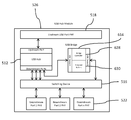
- FIG. 6 illustrates the different components of the combination USB hub/bridge IC shown in FIG. 5 ;
- FIG. 7 illustrates one possible endpoint configuration of the USB bridge shown in FIGS. 5 and 6 ;
- FIG. 8 illustrates an example implementation of a head unit software architecture
- FIG. 9 illustrates an example of a USB hub power module
- FIG. 10 illustrates another example of a USB hub power module.
- FIG. 4 illustrates a system which is in accordance with an embodiment of the present invention.
- the system is configured to effectively render a vehicle's embedded USB host compatible with consumer devices which are configured to also act as USB host or USB device.
- the system is in the form of a self-powered USB hub module 410 having a USB hub 412 , a USB bridge 414 , and a switching device 416 implemented as discrete devices.
- the USB hub 412 is preferably provided in the form of an integrated circuit (IC), and is configured (via an upstream USB port 418 ) connected to a vehicle's embedded USB host (such as a USB host in a head unit—not shown) via vehicle internal wiring, such as, in one embodiment, via a single USB data cable 420 between the head unit and USB hub 412 .
- IC integrated circuit
- the USB hub 412 also includes a plurality of downstream USB ports 422 , at least one of which is connected to the USB bridge 414 (which also is preferably provided in the form of an integrated circuit (IC)). At least one downstream USB port 422 of the USB hub 412 is connected to the switching device 416 (such as USB analog multiplexing switches, for example).
- the switching device 416 is configured to be connected to at least one USB port 422 in the vehicle for connection to a consumer device.
- the USB bridge 414 is configured to effectively control the switching device 416 although other control mechanisms are envisioned.
- the USB hub module 410 is configured such that signals received from at least one USB port 422 are received by the switching device 416 , and the switching device 416 routes the signals to the USB bridge 414 or the USB hub 412 .
- the USB bridge 414 processes the USB packets from the downstream USB port 422 and provides them to the USB hub 412 , thereby rendering the consumer device compatible with the vehicle's embedded USB host.
- the USB bridge 414 controls the switching device 416 such that the switching device 416 provides the USB signaling directly to the USB hub 412 , bypassing the USB bridge 414 .
- the system also includes Power Management structure 424 , as well as some other conventional structure not specifically shown in FIG. 4 , but which would be readily assumed to be present by one having ordinary skill in the art.
- the head unit controls the switching device 416 via the USB bridge hardware or any other convenient means of control.
- the head unit software application may choose to enable, for example, a phone on any one of the consumer USB ports, by requesting, commanding or otherwise knowing the phone is required to be in USB host mode and commanding the routing of the specific USB port the phone is attached to the USB bridge 414 .
- the phone Once routed to the USB bridge 414 , the phone will detect a USB device is connected and the phone will begin the standard USB enumeration sequence.
- the detection and enumeration processes are defined by USB standards and not explained here in detail. However, for purposes of describing the operation of the invention, a general understanding is provided herein.
- USB descriptor requests from the USB host and USB descriptor responses from the USB device that allow the Host to determine the capabilities and functions of the USB device and configure the USB device for operation.
- USB host will then load the appropriate USB driver(s) and applications to support in the functionality that the USB device provides.
- responses to the descriptor requests made by the phone are either answered locally by the Bridge or preferably, the requests are forwarded through the USB bridge 414 to the head unit where its device drivers process the request and return the response.
- the descriptor responses from the device driver are conveyed to the USB bridge 414 , which then, in turn, passes them to the phone.
- the USB bridge 414 appears as a transparent component in the USB system architecture.
- the system capabilities are controlled by the head unit and the system remains flexible without need for changes to the USB bridge firmware or hardware when the system designer requires changes to the descriptor responses.
- the head unit's USB functional capabilities are known to the consumer device and the consumer device may enable use of those functions over USB communication. At this point, the consumer device or the head unit may begin activating any number of supported services such as data connections, streaming audio and streaming video to and from the vehicle via the USB bridge 414 .
- FIG. 4 shows just one USB bridge 414 that any one of the downstream USB ports 422 can be routed to.
- just one USB bridge 414 only one downstream USB port 422 can be connected to a USB host at a time.
- each downstream port of the USB hub has a dedicated USB bridge, then multiple downstream ports can support connection to USB host devices at the same time.
- any consumer port can be in either USB host or USB device mode at any time independently of the others.
- FIG. 5 illustrates an alternative embodiment of a USB hub module 510 wherein the switching device 516 comprises USB routing logic, and both the switching device 516 and the USB bridge 514 are integrated with the USB hub 512 in a combination USB hub/bridge integrated circuit (IC) 526 .
- IC USB hub/bridge integrated circuit
- FIG. 6 illustrates the internal components of the USB hub/bridge IC 526 shown in FIG. 5 .
- the components of the USB bridge 614 include a bridge controller 628 as well as endpoint buffers 630 . While the exact configuration of endpoints is effectively up to the system designer to choose for a particular need, a specific example of one possible endpoint configuration is shown in FIG. 7 ; however, many others are possible.
- the endpoints of the USB bridge 614 may be designed to support multiple pipes of Bulk USB data connections between the host A (head unit) and host B (consumer device).
- the IN endpoints of device A are connected to the OUT endpoints of device B and the OUT endpoints of device A 732 are connected to the IN endpoints of device B 734 .
- the design of the USB bridge 614 may be such that the data flow between the endpoints may be direct or buffered. For example, in the case of direct connection, once a USB packet is received from host A on a device A OUT endpoint, the internal logic of the USB bridge 614 moves to packet to the device B IN endpoint if it is available.
- Such buffers are not required, but are envisioned, to improve system throughput performance in certain circumstances where one of the USB hosts is occasionally busy and not keeping up with USB transactions at the same rate as the other USB host.
- the USB bridge hardware has IN and OUT endpoints on device A mapped to OUT and IN endpoints respectively on device B, thus forming a bidirectional bridge that passes USB traffic between two USB hosts with bandwidth sufficient to support the application requirements of the system.
- device A 732 and device B 734 provide a bidirectional control endpoint connected to their respective USB hosts.
- Control endpoints are required per the USB standard to support USB defined control messages between the host and device both during and after the enumeration sequence.
- USB endpoints may also be utilized per USB standard to employ messages intended to control user defined custom device specific behavior, referred to as vendor specific messages.
- the control endpoints are mapped to the bridge controller 628 .
- the BC logic may be implemented in hardware or preferably software.
- the bridge controller 628 provides the capability to send, receive and process USB standard control endpoint messages as well as vendor specific messages essential to the control and operation of the USB bridge 614 .
- host A requests and receives descriptors from the bridge controller 628 via the control endpoint. Once complete, host A then loads the bridge driver in its software stack and configures the custom Bridge hardware for operation. Host A can then control the functions of the USB bridge 614 , such as USB switch routing control. The system is now ready to accept connection with USB host mode consumer devices on device B 734 of the USB bridge 614 . When such a connection is made, the bridge controller 628 will notify the bridge driver in host A by sending a message on the control endpoint to host A. Further, host B will begin sending descriptor requests on the control endpoint to device B 734 in the USB bridge 614 .
- the bridge controller 628 receives theses requests, encapsulates them with information that identifies them as descriptor requests from host B and passes them to the bridge driver on host A using the control endpoint.
- the host A bridge driver receives these requests, identifies them as descriptor requests and passes the requests on to other software components in host A system and waits for the descriptor responses.
- the descriptor responses are encapsulated by the bridge driver to indicate they are descriptor responses that are to be forwarded to host B.
- the response is then sent to the bridge controller 628 via the control endpoint.
- the bridge controller 628 receives them, identifies them as descriptor responses that should be forwarded to device B and places them on the control endpoint for device B 734 . This process of receiving and forwarding messages back and forth between the two hosts continues until the enumeration process is complete with host B. From that point on the two hosts may begin to use the IN and OUT endpoints to transfer application data and services over the bulk endpoints.
- FIG. 8 illustrates one possible configuration of the system architecture including software components in the head unit 310 interfacing with the USB hub module 410 .
- the operating system and software architecture can be constructed to support the functions of the USB hub module 410 .
- a typical Linux implementation is shown including the USB hub module 410 and the head unit 310 .
- the system design utilizes standard Linux kernel components and configurations and should be familiar to those skilled in the art.
- the head unit's USB host controller hardware is driven by the host controller driver.
- the host controller driver is connected to the USB core.
- the USB core connects the host controller driver with the standard USB Linux device drivers and the custom bridge driver.
- the bridge driver is configured to optionally connect directly to the user space application software or to the USB gadget driver depending on system architecture.
- the custom bridge driver plays a dual role of both controlling the functions of the bridge hardware as well as providing a data path between the gadget device drivers and applications running on the head unit 310 .
- the architecture illustrated is capable of handling both the operation and data paths associated with the USB bridge 414 and the USB hub 412 at the same time, thus allowing concurrent operation of consumer devices operating in USB device mode with consumer devices operating in USB host mode.
- the USB hub module 410 supports simultaneous active USB data connections between the head unit 310 and multiple consumer devices, at least one of which being in host mode while the others are in device mode.
- the USB hub module 410 supports simultaneous active USB data connections between the head unit 310 and some combination of embedded and consumer USB devices along with at least one device being in host mode. While it is understood that the software functions of the head unit 310 are essential to building a complete system, the designs of which can vary significantly and this example is provided only as a means of demonstrating one way to utilize the functionality of the present invention.
- FIG. 9 illustrates a USB hub power module 910 that includes USB power delivery capability as described USB Power Delivery Specification Rev. 3.0 v1.0 published Mar. 25, 2106 by the USB Implementer's Forum, Inc.
- This technology provides the means for the USB hub power module 910 to provide greater charging capabilities to the consumer devices connected to the downstream ports.
- the USB hub power module 910 has at least one downstream port connector 936 that conforms to the USB Type C standard as described in the USB Type-C Cable and Connector Specification, Revision 1.2 published Mar. 25, 2106 by the USB Implementer's Forum, Inc.
- this USB hub power module 910 further includes adjustable voltage power supplies 938 , power control logic circuits 940 to facilitate handshaking over the CC 1 and CC 2 pins, and a communication control stack that is integral to the logic circuits.
- the USB Type-C connector requirements include data transmissions between the electrical power provider (source) and the electrical power consumer (sink) on CC 1 and CC 2 pins defined in the USB Type C standard as a handshaking function.
- the source in this case is the USB hub power module 910 and the sink is the consumer device (not shown) connected to the downstream port connector 936 .
- USB hub power module 910 may be added to the USB hub power module 910 as shown in FIG. 9 .
- additional logic circuits may be added to the USB hub power module 910 in the form of separate discrete IC's and passive components.
- the logic circuits, communication stack, and physical layer interface functions would be integrated in the USB hub/bridge IC 926 , thereby reducing bill of material costs and manufacturing costs.
- USB hub power module 1010 As alternate embodiment of the USB hub power module 1010 is shown in FIG. 10 .
- the power control logic circuits are further integrated in a USB hub/bridge IC 1026 , thereby further reducing bill of material costs and manufacturing costs.
Abstract
Description
Claims (19)
Priority Applications (7)
| Application Number | Priority Date | Filing Date | Title |
|---|---|---|---|
| US15/257,096 US9645962B2 (en) | 2013-09-26 | 2016-09-06 | Flexible mobile device connectivity to automotive systems with USB hubs |
| JP2017165240A JP2018073392A (en) | 2016-09-06 | 2017-08-30 | Flexible mobile device connectivity to automotive systems with usb hubs |
| EP17189201.1A EP3291098A1 (en) | 2016-09-06 | 2017-09-04 | Flexible mobile device connectivity to automotive systems with usb hubs |
| KR1020170112626A KR102332392B1 (en) | 2016-09-06 | 2017-09-04 | Flexible mobile device connectivity to automotive systems with usb hubs |
| CN202111256040.9A CN113986793A (en) | 2016-09-06 | 2017-09-06 | Flexible connection of mobile devices to automotive systems with USB hubs |
| CN201710796332.9A CN108009108B (en) | 2016-09-06 | 2017-09-06 | USB concentrator module |
| KR1020210163329A KR102360664B1 (en) | 2016-09-06 | 2021-11-24 | Flexible mobile device connectivity to automotive systems with usb hubs |
Applications Claiming Priority (3)
| Application Number | Priority Date | Filing Date | Title |
|---|---|---|---|
| US201361882915P | 2013-09-26 | 2013-09-26 | |
| US14/487,947 US9460037B2 (en) | 2013-09-26 | 2014-09-16 | Flexible mobile device connectivity to automotive systems with USB hubs |
| US15/257,096 US9645962B2 (en) | 2013-09-26 | 2016-09-06 | Flexible mobile device connectivity to automotive systems with USB hubs |
Related Parent Applications (1)
| Application Number | Title | Priority Date | Filing Date |
|---|---|---|---|
| US14/487,947 Continuation-In-Part US9460037B2 (en) | 2013-09-26 | 2014-09-16 | Flexible mobile device connectivity to automotive systems with USB hubs |
Publications (2)
| Publication Number | Publication Date |
|---|---|
| US20160371213A1 US20160371213A1 (en) | 2016-12-22 |
| US9645962B2 true US9645962B2 (en) | 2017-05-09 |
Family
ID=57587928
Family Applications (1)
| Application Number | Title | Priority Date | Filing Date |
|---|---|---|---|
| US15/257,096 Active US9645962B2 (en) | 2013-09-26 | 2016-09-06 | Flexible mobile device connectivity to automotive systems with USB hubs |
Country Status (1)
| Country | Link |
|---|---|
| US (1) | US9645962B2 (en) |
Cited By (7)
| Publication number | Priority date | Publication date | Assignee | Title |
|---|---|---|---|---|
| US20150309954A1 (en) * | 2014-04-29 | 2015-10-29 | Mcci Corporation | Apparatus and methods for dynamic role switching among usb hosts and devices |
| US20160092391A1 (en) * | 2014-09-25 | 2016-03-31 | Hyundai Motor Company | Interface apparatus, vehicle having the same, and method of controlling the same |
| US20170194756A1 (en) * | 2015-12-31 | 2017-07-06 | Le Holdings (Beijing) Co., Ltd. | Usb data cable containing extension interface and control method thereof |
| US10266131B2 (en) * | 2016-04-14 | 2019-04-23 | GM Global Technology Operations LLC | Vehicle systems and methods using USB interfaces |
| US11010321B2 (en) | 2016-12-12 | 2021-05-18 | Crossport Network Solutions Inc. | Ad-hoc sensing switched data circuit for connecting network hosts and peripherals |
| US11086374B2 (en) | 2019-01-30 | 2021-08-10 | Jmicron Technology Corp. | Transmission interface circuit having a plurality of power supply paths whereby transmission are placed in one of a conductive or nonconductive state |
| US20220303385A1 (en) * | 2021-03-17 | 2022-09-22 | Prolific Technology Inc. | In-vehicle entertainment system having functionality of operation interface switchable |
Families Citing this family (12)
| Publication number | Priority date | Publication date | Assignee | Title |
|---|---|---|---|---|
| US10224727B2 (en) * | 2015-06-30 | 2019-03-05 | Dong-Sheng Li | Multi-functional hub integrated with AC power supply |
| WO2017222552A1 (en) * | 2016-06-24 | 2017-12-28 | Intel Corporation | Dual role capable connectors for separable portion of computing apparatus |
| US10990707B1 (en) * | 2017-03-30 | 2021-04-27 | Comodo Security Solutions, Inc. | Device for safe data signing |
| US10331604B2 (en) * | 2017-05-17 | 2019-06-25 | Microchip Technology Incorporated | USB host-to-host auto-switching |
| CN107451082B (en) * | 2017-08-01 | 2019-07-30 | 中孚信息股份有限公司 | A kind of integrated HUB hub and application program system used in conjunction with |
| US11765559B2 (en) * | 2017-08-29 | 2023-09-19 | Microlab/Fxr Llc | Passive radio frequency components with voltage standing wave ratio monitors |
| CA3191348A1 (en) * | 2017-09-20 | 2019-03-28 | Infinity Tribe Group Inc. | Remotely controlled technician surrogate device |
| TWI647571B (en) * | 2017-09-20 | 2019-01-11 | 旺玖科技股份有限公司 | Usb hub |
| US10635618B2 (en) | 2018-09-17 | 2020-04-28 | 2236008 Ontario Inc. | Modifying a configuration of a port hub |
| US10574070B1 (en) * | 2019-01-19 | 2020-02-25 | Simpower Technology Inc. | Multi-functional hub integrated with AC power supply |
| US11379026B2 (en) * | 2019-07-30 | 2022-07-05 | Samsung Electronics Co., Ltd. | Electronic device for preventing damage of USB device and operating method thereof |
| TWI714243B (en) * | 2019-09-03 | 2020-12-21 | 威鋒電子股份有限公司 | Usb integrated circuit |
Citations (29)
| Publication number | Priority date | Publication date | Assignee | Title |
|---|---|---|---|---|
| US6073188A (en) | 1997-07-25 | 2000-06-06 | Compaq Computer Corporation | Electronic switchbox for selection and sharing of internal peripheral devices among different computers, the internal peripheral devices located in slots of a chassis |
| TW470887B (en) | 2000-03-10 | 2002-01-01 | Winbond Electronics Corp | USB hub having multiple upstream ports and capable of switching between different hosts and computer system using the USB hub |
| US20030167345A1 (en) | 2002-02-25 | 2003-09-04 | Knight Alexander N. | Communications bridge between a vehicle information network and a remote system |
| JP2003256351A (en) | 2002-03-04 | 2003-09-12 | Yamaha Corp | Usb hub |
| US6732219B1 (en) | 2001-02-23 | 2004-05-04 | Hewlett-Packard Development Company, L.P. | Dynamic allocation of devices to host controllers |
| US6934793B2 (en) | 2002-06-03 | 2005-08-23 | Action Star Enterprise Co., Ltd. | USB sharer for use with an external USB device |
| US6957287B2 (en) | 2001-11-09 | 2005-10-18 | Aten International Co., Ltd. | Asynchronous/synchronous KVMP switch for console and peripheral devices |
| US20060056401A1 (en) | 2004-09-14 | 2006-03-16 | Standard Microsystems Corporation | Peripheral sharing USB hub |
| US7130656B2 (en) | 1998-04-30 | 2006-10-31 | Clarion Co., Ltd. | Automotive information system and method of controlling the same, recording medium storing control program, disk playback apparatus, and semiconductor integrated circuit |
| US20070067553A1 (en) | 2005-09-01 | 2007-03-22 | Alcor Micro, Corp. | Design of a signal switch |
| US20070086724A1 (en) | 2002-07-17 | 2007-04-19 | Jeff Grady | Interface systems for portable digital media storage and playback devices |
| US20070156293A1 (en) | 2005-12-30 | 2007-07-05 | Kellzi Krikor G | Interface system |
| US7280802B2 (en) | 2002-07-17 | 2007-10-09 | Netalog, Inc. | FM transmitter and power supply/charging assembly for MP3 player |
| US20080005262A1 (en) | 2006-06-16 | 2008-01-03 | Henry Wurzburg | Peripheral Sharing USB Hub for a Wireless Host |
| US7478191B2 (en) | 2006-04-14 | 2009-01-13 | Standard Microsystems Corporation | Method for automatically switching USB peripherals between USB hosts |
| US7523243B2 (en) | 2006-04-14 | 2009-04-21 | Standard Microsystems Corporation | Multi-host USB device controller |
| US20090117890A1 (en) | 2007-05-14 | 2009-05-07 | Kopin Corporation | Mobile wireless display for accessing data from a host and method for controlling |
| US20110054721A1 (en) | 2007-02-16 | 2011-03-03 | Intelligent Automation Corporation | Vehicle monitoring system |
| US20110124300A1 (en) | 2005-11-26 | 2011-05-26 | David Sinai | Audio device and method |
| US20110208892A1 (en) * | 2010-02-25 | 2011-08-25 | Fresco Logic, Inc. | Method and apparatus for scheduling transactions in a multi-speed bus environment |
| US20110208891A1 (en) * | 2010-02-25 | 2011-08-25 | Fresco Logic, Inc. | Method and apparatus for tracking transactions in a multi-speed bus environment |
| US20120134506A1 (en) | 2005-07-14 | 2012-05-31 | Scosche Industries, Inc. | Wireless media source for communication with devices on data bus of vehicle |
| US20120191811A1 (en) | 2004-10-25 | 2012-07-26 | Stanley Ng | Wireless synchronization between media player and host device |
| US20120290859A1 (en) | 2011-05-09 | 2012-11-15 | Continental Automotive Systems, Inc. | Usb host wake up via a usb device when in shut down mode |
| US20130053003A1 (en) | 2011-08-31 | 2013-02-28 | Toyota Motor Engineering & Manufacturing North America, Inc. | Auxiliary device and system for adding web-based multimedia applications to a multimedia device |
| US20130106750A1 (en) | 2011-10-28 | 2013-05-02 | Fuminobu Kurosawa | Connecting Touch Screen Phones in a Vehicle |
| US8447598B2 (en) | 2007-12-05 | 2013-05-21 | Johnson Controls Technology Company | Vehicle user interface systems and methods |
| US8447890B1 (en) | 2009-10-30 | 2013-05-21 | Cypress Semiconductor Corporation | Operation of multiple masters/hosts through a hub |
| US20160132448A1 (en) * | 2014-11-07 | 2016-05-12 | Texas Instruments Incorporated | Hub module with a single bridge shared among multiple connection ports to support role reversal |
-
2016
- 2016-09-06 US US15/257,096 patent/US9645962B2/en active Active
Patent Citations (30)
| Publication number | Priority date | Publication date | Assignee | Title |
|---|---|---|---|---|
| US6073188A (en) | 1997-07-25 | 2000-06-06 | Compaq Computer Corporation | Electronic switchbox for selection and sharing of internal peripheral devices among different computers, the internal peripheral devices located in slots of a chassis |
| US7130656B2 (en) | 1998-04-30 | 2006-10-31 | Clarion Co., Ltd. | Automotive information system and method of controlling the same, recording medium storing control program, disk playback apparatus, and semiconductor integrated circuit |
| TW470887B (en) | 2000-03-10 | 2002-01-01 | Winbond Electronics Corp | USB hub having multiple upstream ports and capable of switching between different hosts and computer system using the USB hub |
| US6732219B1 (en) | 2001-02-23 | 2004-05-04 | Hewlett-Packard Development Company, L.P. | Dynamic allocation of devices to host controllers |
| US6957287B2 (en) | 2001-11-09 | 2005-10-18 | Aten International Co., Ltd. | Asynchronous/synchronous KVMP switch for console and peripheral devices |
| US20030167345A1 (en) | 2002-02-25 | 2003-09-04 | Knight Alexander N. | Communications bridge between a vehicle information network and a remote system |
| JP2003256351A (en) | 2002-03-04 | 2003-09-12 | Yamaha Corp | Usb hub |
| US6934793B2 (en) | 2002-06-03 | 2005-08-23 | Action Star Enterprise Co., Ltd. | USB sharer for use with an external USB device |
| US20070086724A1 (en) | 2002-07-17 | 2007-04-19 | Jeff Grady | Interface systems for portable digital media storage and playback devices |
| US7280802B2 (en) | 2002-07-17 | 2007-10-09 | Netalog, Inc. | FM transmitter and power supply/charging assembly for MP3 player |
| US20060056401A1 (en) | 2004-09-14 | 2006-03-16 | Standard Microsystems Corporation | Peripheral sharing USB hub |
| US20120191811A1 (en) | 2004-10-25 | 2012-07-26 | Stanley Ng | Wireless synchronization between media player and host device |
| US20120134506A1 (en) | 2005-07-14 | 2012-05-31 | Scosche Industries, Inc. | Wireless media source for communication with devices on data bus of vehicle |
| US20070067553A1 (en) | 2005-09-01 | 2007-03-22 | Alcor Micro, Corp. | Design of a signal switch |
| US20110124300A1 (en) | 2005-11-26 | 2011-05-26 | David Sinai | Audio device and method |
| US20070156293A1 (en) | 2005-12-30 | 2007-07-05 | Kellzi Krikor G | Interface system |
| US7478191B2 (en) | 2006-04-14 | 2009-01-13 | Standard Microsystems Corporation | Method for automatically switching USB peripherals between USB hosts |
| US7627708B2 (en) | 2006-04-14 | 2009-12-01 | Standard Microsystems Corporation | Multi-host USB device |
| US7523243B2 (en) | 2006-04-14 | 2009-04-21 | Standard Microsystems Corporation | Multi-host USB device controller |
| US20080005262A1 (en) | 2006-06-16 | 2008-01-03 | Henry Wurzburg | Peripheral Sharing USB Hub for a Wireless Host |
| US20110054721A1 (en) | 2007-02-16 | 2011-03-03 | Intelligent Automation Corporation | Vehicle monitoring system |
| US20090117890A1 (en) | 2007-05-14 | 2009-05-07 | Kopin Corporation | Mobile wireless display for accessing data from a host and method for controlling |
| US8447598B2 (en) | 2007-12-05 | 2013-05-21 | Johnson Controls Technology Company | Vehicle user interface systems and methods |
| US8447890B1 (en) | 2009-10-30 | 2013-05-21 | Cypress Semiconductor Corporation | Operation of multiple masters/hosts through a hub |
| US20110208892A1 (en) * | 2010-02-25 | 2011-08-25 | Fresco Logic, Inc. | Method and apparatus for scheduling transactions in a multi-speed bus environment |
| US20110208891A1 (en) * | 2010-02-25 | 2011-08-25 | Fresco Logic, Inc. | Method and apparatus for tracking transactions in a multi-speed bus environment |
| US20120290859A1 (en) | 2011-05-09 | 2012-11-15 | Continental Automotive Systems, Inc. | Usb host wake up via a usb device when in shut down mode |
| US20130053003A1 (en) | 2011-08-31 | 2013-02-28 | Toyota Motor Engineering & Manufacturing North America, Inc. | Auxiliary device and system for adding web-based multimedia applications to a multimedia device |
| US20130106750A1 (en) | 2011-10-28 | 2013-05-02 | Fuminobu Kurosawa | Connecting Touch Screen Phones in a Vehicle |
| US20160132448A1 (en) * | 2014-11-07 | 2016-05-12 | Texas Instruments Incorporated | Hub module with a single bridge shared among multiple connection ports to support role reversal |
Non-Patent Citations (7)
| Title |
|---|
| "APC USB 2.0 Host Controller-Device Driver Download", http://www.liutilities.com/devicedriver/apcusb20hostcontroller/, Jul. 2002. |
| "FFI Rapport-A Study of Computer Interfaces for Soldier Systems", Lars Erik Olsen & Joakin Flathagen, Norwegian Defence Research Establishment, Oct. 10, 2005. |
| "Peripheral-Sharing Hardware Suits Education's Needs to a 'T'", Terian Tyre, T H E Journal (Technological Horizons In Education), Oct. 1988. |
| "USB 2.0 Autoswitch User's Manual", Lindy Electronics Limited & Lindy-Elektronic GMBH, Sep. 2002. |
| "APC USB 2.0 Host Controller—Device Driver Download", http://www.liutilities.com/devicedriver/apcusb20hostcontroller/, Jul. 2002. |
| "FFI Rapport—A Study of Computer Interfaces for Soldier Systems", Lars Erik Olsen & Joakin Flathagen, Norwegian Defence Research Establishment, Oct. 10, 2005. |
| "Peripheral-Sharing Hardware Suits Education's Needs to a ‘T’", Terian Tyre, T H E Journal (Technological Horizons In Education), Oct. 1988. |
Cited By (12)
| Publication number | Priority date | Publication date | Assignee | Title |
|---|---|---|---|---|
| US20150309954A1 (en) * | 2014-04-29 | 2015-10-29 | Mcci Corporation | Apparatus and methods for dynamic role switching among usb hosts and devices |
| US9811488B2 (en) * | 2014-04-29 | 2017-11-07 | Mcci Corporation | Apparatus and methods for dynamic role switching among USB hosts and devices |
| US10585832B2 (en) * | 2014-04-29 | 2020-03-10 | Mcci Corporation | Apparatus and methods for dynamic role switching among USB hosts and devices |
| US10846255B2 (en) | 2014-04-29 | 2020-11-24 | Mcci Corporation | Apparatus and methods for dynamic role switching among USB hosts and devices |
| US20160092391A1 (en) * | 2014-09-25 | 2016-03-31 | Hyundai Motor Company | Interface apparatus, vehicle having the same, and method of controlling the same |
| US20170194756A1 (en) * | 2015-12-31 | 2017-07-06 | Le Holdings (Beijing) Co., Ltd. | Usb data cable containing extension interface and control method thereof |
| US10266131B2 (en) * | 2016-04-14 | 2019-04-23 | GM Global Technology Operations LLC | Vehicle systems and methods using USB interfaces |
| US11010321B2 (en) | 2016-12-12 | 2021-05-18 | Crossport Network Solutions Inc. | Ad-hoc sensing switched data circuit for connecting network hosts and peripherals |
| US11086374B2 (en) | 2019-01-30 | 2021-08-10 | Jmicron Technology Corp. | Transmission interface circuit having a plurality of power supply paths whereby transmission are placed in one of a conductive or nonconductive state |
| TWI736834B (en) * | 2019-01-30 | 2021-08-21 | 智微科技股份有限公司 | Transmission interface circuit |
| US20220303385A1 (en) * | 2021-03-17 | 2022-09-22 | Prolific Technology Inc. | In-vehicle entertainment system having functionality of operation interface switchable |
| US11825009B2 (en) * | 2021-03-17 | 2023-11-21 | Prolific Technology Inc. | In-vehicle entertainment system having functionality of operation interface switchable |
Also Published As
| Publication number | Publication date |
|---|---|
| US20160371213A1 (en) | 2016-12-22 |
Similar Documents
| Publication | Publication Date | Title |
|---|---|---|
| US11681643B2 (en) | Flexible mobile device connectivity to automotive systems with USB hubs | |
| US9645962B2 (en) | Flexible mobile device connectivity to automotive systems with USB hubs | |
| KR102360664B1 (en) | Flexible mobile device connectivity to automotive systems with usb hubs | |
| US10943640B2 (en) | Apparatus, method and system for providing termination for multiple chips of an integrated circuit package | |
| US10585832B2 (en) | Apparatus and methods for dynamic role switching among USB hosts and devices | |
| US20060106962A1 (en) | USB On-The-Go implementation | |
| EP2333672B1 (en) | Inter-die interconnection interface | |
| JP2002288112A (en) | Communication control semiconductor device and interface system | |
| CN107391419B (en) | Support general sequence busbar concentrator of many host computers and automobile-used host computer | |
| US20120210093A1 (en) | Method and apparatus for interfacing multiple dies with mapping to modify source identity |
Legal Events
| Date | Code | Title | Description |
|---|---|---|---|
| AS | Assignment |
Owner name: DELPHI TECHNOLOGIES, INC., MICHIGAN Free format text: ASSIGNMENT OF ASSIGNORS INTEREST;ASSIGNORS:VOTO, ROBERT M.;YEDA, SHYAMBABU;PETKU, CRAIG;REEL/FRAME:040157/0235 Effective date: 20161027 |
|
| STCF | Information on status: patent grant |
Free format text: PATENTED CASE |
|
| AS | Assignment |
Owner name: APTIV TECHNOLOGIES LIMITED, BARBADOS Free format text: ASSIGNMENT OF ASSIGNORS INTEREST;ASSIGNOR:DELPHI TECHNOLOGIES INC.;REEL/FRAME:047143/0874 Effective date: 20180101 |
|
| MAFP | Maintenance fee payment |
Free format text: PAYMENT OF MAINTENANCE FEE, 4TH YEAR, LARGE ENTITY (ORIGINAL EVENT CODE: M1551); ENTITY STATUS OF PATENT OWNER: LARGE ENTITY Year of fee payment: 4 |
|
| AS | Assignment |
Owner name: APTIV TECHNOLOGIES (2) S.A R.L., LUXEMBOURG Free format text: ENTITY CONVERSION;ASSIGNOR:APTIV TECHNOLOGIES LIMITED;REEL/FRAME:066341/0787 Effective date: 20230818 Owner name: APTIV MANUFACTURING MANAGEMENT SERVICES S.A R.L., LUXEMBOURG Free format text: MERGER;ASSIGNOR:APTIV TECHNOLOGIES (2) S.A R.L.;REEL/FRAME:066342/0518 Effective date: 20231005 |
|
| AS | Assignment |
Owner name: APTIV TECHNOLOGIES AG, SWITZERLAND Free format text: ASSIGNMENT OF ASSIGNORS INTEREST;ASSIGNOR:APTIV MANUFACTURING MANAGEMENT SERVICES S.A R.L.;REEL/FRAME:066163/0001 Effective date: 20231006 |
|
| IPR | Aia trial proceeding filed before the patent and appeal board: inter partes review |
Free format text: TRIAL NO: IPR2024-00229 Opponent name: MICROCHIP TECHNOLOGY, INC. Effective date: 20231227 |