JP2006347310A - Airbag device with horn switch - Google Patents
Airbag device with horn switch Download PDFInfo
- Publication number
- JP2006347310A JP2006347310A JP2005174803A JP2005174803A JP2006347310A JP 2006347310 A JP2006347310 A JP 2006347310A JP 2005174803 A JP2005174803 A JP 2005174803A JP 2005174803 A JP2005174803 A JP 2005174803A JP 2006347310 A JP2006347310 A JP 2006347310A
- Authority
- JP
- Japan
- Prior art keywords
- guide surface
- taper
- movable
- horn switch
- airbag
- Prior art date
- Legal status (The legal status is an assumption and is not a legal conclusion. Google has not performed a legal analysis and makes no representation as to the accuracy of the status listed.)
- Granted
Links
Images


Abstract
Description
この発明は、車両のステアリングに組込まれるホーンスイッチ付エアバッグ装置に関する。 The present invention relates to an air bag device with a horn switch incorporated in a steering of a vehicle.
車両のステアリングには、ホーンを鳴らすためのホーンスイッチ付エアバッグ装置が組込まれている。 An air bag device with a horn switch for ringing a horn is incorporated in the vehicle steering.
一般的なホーンスイッチ付エアバッグ装置は、固定プレートと、この固定プレートに対して接近離隔移動自在に設けられた可動プレートとを備えている。可動プレートは、バネ等により固定プレートに対して離反する方向に付勢されており、ステアリングの略中央部に設けられたカバープレートを押動することによって固定プレートに対して接近移動する。また、固定プレート及び可動プレートに接点が組込まれており、可動プレートを固定プレートに接近移動させることによって、両接点が接触してホーンを鳴らす構成となっている。 A general airbag device with a horn switch includes a fixed plate and a movable plate provided so as to be movable toward and away from the fixed plate. The movable plate is biased in a direction away from the fixed plate by a spring or the like, and moves closer to the fixed plate by pushing a cover plate provided at a substantially central portion of the steering. In addition, contacts are incorporated in the fixed plate and the movable plate, and by moving the movable plate closer to the fixed plate, the two contacts come into contact with each other and sound the horn.
可動プレートは、例えば、固定プレートに対して次のような構成で接近離隔移動自在に支持される。すなわち、可動プレートにボルト等による支持部材が立設される。固定プレート側に支持部材を挿通可能な挿通孔が形成されている。そして、上記支持部材を挿通孔内に挿通させた状態で、支持部材の先端部に抜止部材が取付けられる。これにより、支持部材はその先端側の抜止部材と基端部分との間で挿通孔を挿通自在となり、この範囲で可動プレートが固定プレートに対して接近離隔移動自在に支持されることになる。 For example, the movable plate is supported so as to be movable toward and away from the fixed plate in the following configuration. That is, a support member such as a bolt is erected on the movable plate. An insertion hole through which the support member can be inserted is formed on the fixed plate side. And the retaining member is attached to the front-end | tip part of a support member in the state which has penetrated the said support member in the penetration hole. Thus, the support member can be inserted through the insertion hole between the retaining member on the distal end side and the base end portion, and the movable plate is supported so as to be movable toward and away from the fixed plate in this range.
この場合、通常状態で、固定プレートと可動プレートとが支持部材を介して導通状態となるのを防止するため、支持部材自体を樹脂で形成したり、或は、上記支持部材と挿通孔との間に、樹脂製の部材を介在させる等の構成が採用される。 In this case, in order to prevent the fixed plate and the movable plate from being brought into conduction through the support member in a normal state, the support member itself is formed of resin, or the support member and the insertion hole A configuration in which a resin member is interposed is employed.
なお、ステアリングにホーンスイッチを組込んだホーンスイッチ付エアバッグ装置を開示した先行技術文献としては、例えば、特許文献1に記載のものがある。 In addition, as a prior art document which disclosed the airbag apparatus with a horn switch which incorporated the horn switch in the steering, there exists a thing of the patent document 1, for example.
しかしながら、ホーンスイッチ付エアバッグ装置において、エアバッグがガス圧等により膨張展開すると、可動プレートに対して固定プレートから離反する方向への大きな衝撃力が加わる。 However, in the airbag device with a horn switch, when the airbag is inflated and deployed due to gas pressure or the like, a large impact force is applied to the movable plate in a direction away from the fixed plate.
この場合に、上記挿通孔の周縁部で、上記樹脂で形成した部材に過大な剪断力が加わり、該樹脂で形成した部材が破損したり外れたりする恐れがある。そのため、挿通孔の両側から樹脂部品を強固に固定するなどといった構成が必要であり、作業性が悪くコスト増要因となっていた。 In this case, an excessive shearing force is applied to the member formed of the resin at the peripheral portion of the insertion hole, and the member formed of the resin may be damaged or detached. For this reason, it is necessary to have a configuration in which resin parts are firmly fixed from both sides of the insertion hole, resulting in poor workability and a cost increase factor.
そこで、本発明は、エアバッグ展開等による過大な力が加わったような場合に、比較的安価でその過大な力に耐え得るホーンスイッチ付エアバッグ装置を提供することを目的とする。 Therefore, an object of the present invention is to provide an air bag device with a horn switch that is relatively inexpensive and can withstand the excessive force when an excessive force is applied due to airbag deployment or the like.
この発明に係るホーンスイッチ付エアバッグ装置は、ステアリングホイールに組付けられるホーンスイッチ付エアバッグ装置であって、ステアリングホイールと一体に固定される固定部材と、前記固定部材に対して接近離隔移動自在に配設され、押動操作に連動して移動する可動部材と、前記可動部材に取付けられたエアバッグと、前記固定部材から離反する方向に前記可動部材を付勢する付勢手段と、前記固定部材及び前記可動部材に設けられ、前記可動部材と前記固定部材とが接近移動することで導通するスイッチ部とを備え、前記固定部材と前記可動部材とのうち一方側に支持柱部材が立設されると共に、他方側に前記支持柱部材を挿通可能な挿通孔部が形成され、前記支持柱部材の先端部に、前記支持柱部材の基端側に向けて順次縮径する第1ガイド面を有するテーパ係合部材が取付けられると共に、前記挿通孔部に前記第1ガイド面を受入れ可能でかつその第1ガイド面と同方向に縮径する第2ガイド面を内周形状部分に有するテーパ案内部材が取付けられ、前記テーパ係合部材及び前記テーパ案内部材のうち少なくとも一方が非導電性材料で形成されたものである。 An air bag device with a horn switch according to the present invention is an air bag device with a horn switch that is assembled to a steering wheel, and a fixing member that is fixed integrally with the steering wheel, and is movable toward and away from the fixing member. A movable member that moves in conjunction with a push operation, an airbag attached to the movable member, a biasing means that biases the movable member in a direction away from the fixed member, A switch part provided on the fixed member and the movable member, wherein the movable member and the fixed member are brought into conduction when the movable member and the fixed member are moved closer to each other, and a support column member stands on one side of the fixed member and the movable member. And an insertion hole portion through which the support column member can be inserted is formed on the other side, and the distal end portion of the support column member is gradually contracted toward the proximal end side of the support column member. A taper engaging member having a first guide surface is attached, and a second guide surface that can receive the first guide surface in the insertion hole and has a diameter reduced in the same direction as the first guide surface A taper guide member having a shape portion is attached, and at least one of the taper engagement member and the taper guide member is formed of a non-conductive material.
なお、前記可動部材が前記固定部材に対して最も接近した状態で、前記第1ガイド面と前記第2ガイド面とが重なる位置関係となるように設定されていてもよい。 The movable member may be set so that the first guide surface and the second guide surface overlap with each other when the movable member is closest to the fixed member.
さらに、前記テーパ案内部材は、端部方向に向けて順次縮径する外周部形状部分を有していてもよい。 Furthermore, the taper guide member may have an outer peripheral shape portion that gradually decreases in diameter toward the end portion.
以上のように構成されたホーンスイッチ付エアバッグ装置によると、前記固定部材と前記可動部材とのうち一方側に支持柱部材が立設されると共に、他方側に前記支持柱部材を挿通可能な挿通孔部が形成され、前記支持柱部材の先端部に、前記支持柱部材の基端側に向けて順次縮径する第1ガイド面を有するテーパ係合部材が取付けられると共に、前記挿通孔部に前記第1ガイド面を受入れ可能でかつその第1ガイド面と同方向に縮径する第2ガイド面を内周形状部分に有するテーパ案内部材が取付けられているため、固定部材と可動部材とが離間した通常状態では、第1ガイド面が第2ガイド面に押付けられて、がたつき防止が図られる。そして、押動操作により可動部材を固定部材に向けて接近移動させると、第1ガイド面と第2ガイド面との間に空間が形成され、テーパ係合部材がテーパ案内部材内を遊動可能になり、押動操作を妨げない。 According to the air bag device with a horn switch configured as described above, a support column member is erected on one side of the fixed member and the movable member, and the support column member can be inserted on the other side. An insertion hole portion is formed, and a tapered engagement member having a first guide surface that is sequentially reduced in diameter toward the proximal end side of the support column member is attached to the distal end portion of the support column member, and the insertion hole portion A taper guide member having a second guide surface that can receive the first guide surface and has a diameter reduced in the same direction as the first guide surface is attached to the inner peripheral portion. In the normal state in which the distance between the first guide surface and the second guide surface is increased, the first guide surface is pressed against the second guide surface to prevent rattling. When the movable member is moved closer to the fixed member by the pushing operation, a space is formed between the first guide surface and the second guide surface, and the taper engagement member can freely move in the taper guide member. The push operation is not hindered.
また、エアバッグ展開時等に、固定部材から離反させる過大な力が可動部材に作用すると、第1ガイド面に対して第2ガイド面が強く押し当てられる状態となる。これにより、比較的安価な構成で、テーパ係合部材及びテーパ案内部材に作用する力に耐え得る。また、この力を受けてテーパ案内部材が抜けないように変形することになるので該テーパ案内部材が挿通孔部から外れ難い。 Further, when an excessive force that separates from the fixed member acts on the movable member when the airbag is deployed, the second guide surface is strongly pressed against the first guide surface. Thereby, it can endure the force which acts on a taper engagement member and a taper guide member with a comparatively cheap structure. Further, since the taper guide member is deformed so as not to come off upon receiving this force, the taper guide member is unlikely to come off from the insertion hole.
また、前記可動部材が前記固定部材に対して最も接近した状態で、前記第1ガイド面と前記第2ガイド面とが重なる位置関係となるように設定されていると、可動部材を固定部材に接近移動させた状態で、テーパ係合部材とテーパ案内部材とが干渉し難くなり、可動部材が円滑に移動する。 Further, when the movable member is set so as to be in a positional relationship where the first guide surface and the second guide surface overlap with each other in a state where the movable member is closest to the fixed member, the movable member is used as the fixed member. The taper engaging member and the taper guide member are less likely to interfere with each other in the approached state, and the movable member moves smoothly.
また、テーパ案内部材は、端部方向に向けて順次縮径する外周部形状部分を有していると、テーパ案内部材を挿通孔部に挿入して取付け易い。 Further, when the taper guide member has an outer peripheral portion shape portion that sequentially decreases in diameter toward the end portion, the taper guide member can be easily attached by inserting the taper guide member into the insertion hole portion.
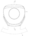
以下、この発明の実施形態に係るホーンスイッチ付エアバッグ装置について説明する。このホーンスイッチ付エアバッグ装置は、エアバッグと一体的にステアリングホイールに組込まれる。図1はホーンスイッチ付エアバッグ装置を示す正面図であり、図2は図1のI−I線断面図、図3はホーンスイッチ付エアバッグ装置を背面側から見た斜視図である。 Hereinafter, an air bag device with a horn switch according to an embodiment of the present invention will be described. The airbag device with a horn switch is incorporated in a steering wheel integrally with the airbag. 1 is a front view showing an air bag device with a horn switch, FIG. 2 is a cross-sectional view taken along the line II of FIG. 1, and FIG. 3 is a perspective view of the air bag device with a horn switch as viewed from the back side.
エアバッグ部分について概略的に説明しておく。エアバッグ12は、車両運転席のステアリングホイールWの略中央部に組込まれるものであり、エアバッグカバー10の内側にエアバッグ12(図2参照)及びガス発生装置14(インフレータともいう、図2参照)が配設されている。
The airbag portion will be schematically described. The
上記エアバッグカバー10は、後述する固定プレート30及び可動プレート40を介してステアリングホイールWの中央ボス部分或はスポーク部分等の取付対象部材に取付られることで、ステアリングホイールWの略中央部に配設される。
The
エアバッグ12は、通常状態では、折畳まれた形態で上記エアバッグカバー10の内側空間内に収容配置されている。そして、車両衝突時等の衝撃検知時には、ガス発生装置14からの噴射ガスがエアバッグ12内に導入されてエアバッグ12が膨張展開する。この膨張展開力によりエアバッグ12がエアバッグカバー10を押し割ってステアリングホイールWの前方に膨張展開する。
In a normal state, the
ホーンスイッチ付エアバッグ装置20は、固定部材としての固定プレート30と可動部材としての可動プレート40とスイッチ部を構成する接点部34a,44aとを備えている。
The airbag device with
固定プレート30は、ステアリングホイールW及び車体側のシャフトに一体に固定される部材である。より具体的には、固定プレート30は、金属板等の導電性板材により略U字板状に形成されており、その内周部に形成された取付片32を介してステアリングホイールWの中央ボス部分或はスポーク部分等の取付対象部材にねじ止等により取付固定される。
The fixed
可動プレート40は、後述する支持柱部材46及び挿通孔部36を介した支持構造により上記固定プレート30に対して接近離隔移動自在に配設されている。そして、上記エアバッグカバー10に対する押動操作に連動して固定プレート30に対して接近離隔移動するように構成されている。
The
より具体的には、可動プレート40は、金属板等の導電性板材により形成されており、上記エアバッグカバー10の背面側の開口を閉塞可能な板形状に形成されると共に、その略中央部に開口孔部42が形成されてなる。
More specifically, the
この可動プレート40は、固定片41を介してエアバッグカバー10の背面側部分に取付固定されている。そして、エアバッグカバー10をその表面側から押動操作すると、これに連動して移動するように構成されている。
The
また、上記開口孔部42内には、ガス発生装置14が取付けられている。ガス発生装置14は、可動プレート40のうち開口孔部42周縁部にねじ止等により固定されている。そして、ガス発生装置14のガス爆発によりエアバッグ12を膨張展開させると、そのエアバッグ12の膨張展開力が可動プレート40にも作用する。このエアバッグ12の展開力により、可動プレート40に対して運転者側への力、即ち、固定プレート30から離反する方向への力が加わる。
A
また、上記固定プレート30及び可動プレート40には、それらの対向方向に突出する突出部34,44が形成されている(図2参照)。これらの突出部34,44の先端部には導電性材料で形成された接点部34a,44aが設けられている。これらの接点部34a,44aをもってホーンを鳴らすためのスイッチ部が構成されている。
Further, the
すなわち、固定プレート30及び可動プレート40が離反した状態では、それら接点部34a,44aは間隔を空けて離間した状態となっている。そして、可動プレート40を移動させて両プレート30,40を接近移動させた状態では、両接点部34a,44aが接触して導通した状態になる。また、固定プレート30、可動プレート40及び両接点部34a,44aを経由するホーンのスイッチ回路が形成されている。そして、両接点部34a,44aが導通状態になることで、上記ホーンのスイッチ回路がオン状態になり、ホーンが鳴るようになっている。
That is, when the
図4はホーンスイッチ付エアバッグ装置の要部拡大断面図であり、図5はテーパ係合部材を示す斜視図であり、図6はテーパ案内部材を示す斜視図である。 4 is an enlarged cross-sectional view of a main part of the airbag device with a horn switch, FIG. 5 is a perspective view showing a taper engagement member, and FIG. 6 is a perspective view showing a taper guide member.
上記可動プレート40は、固定プレート30に対して次の構成により接近離隔移動自在に固定されている。
The
すなわち、可動プレート40に、固定プレート30側に向けて突出するように複数(ここでは3つ)の支持柱部材46が立設されている。この各支持柱部材46の先端部は、後述するテーパ係合部材50を螺合可能なねじ部46sに形成されている。
That is, a plurality (three in this case) of
また、固定プレート30側に、支持柱部材46を挿通可能な挿通孔部36が形成されている。なお、これらの例とは逆に、固定プレート30側に支持柱部が形成されると共に、可動プレート40側に挿通孔部が形成された構成であってもよい。
Further, an
上記支持柱部材46の先端部には、テーパ係合部材50が取付けられると共に、挿通孔部36にテーパ案内部材60が取付けられている。
A
テーパ係合部材50は、支持柱部材46の基端側に向けて順次縮径する第1ガイド面57(図5で斜線を付した部分参照)を有している。
The
より具体的には、テーパ係合部材50は、金属等により形成されており、上記ねじ部46sに螺合可能なナット部51と円環部53とを備えている。そして、ナット部51をねじ部46sに螺合させることで、本テーパ係合部材50は支持柱部材46の先端部に取付固定される。
More specifically, the
また、円環部53は、上記ナット部51から支持柱部材46の基端側に向けて延出する環状に形成されている。この円環部53の外周部が、支持柱部材46の基端側に向けて順次縮径する第1ガイド面57に形成されている。
The
なお、これらナット部51と円環部53とが別部材として形成されており、例えば、ナット部51に対応する部分と支持柱部材46に形成された段部との間に、円環部53に対応する部分が挟持固定される構成であってもよい。
The
テーパ案内部材60は、上記第1ガイド面57を受入れ可能でかつその第1ガイド面57と同方向に縮径する第2ガイド面66a(図6で斜線を付した部分参照)を有している。
The
より具体的には、テーパ案内部材60は、樹脂等の非導電性材料により形成されている。テーパ案内部材60は、係止環状部62の一方面側に係合爪部64が突出形成されてなる。係止環状部62は、上記固定プレート30のうち挿通孔部36の周縁部に可動プレート40側から係合可能な環状部分に形成されている。
More specifically, the
また、この係止環状部62の一方面に、その内周部に沿って間隔をあけて複数(ここでは3つ)の係合爪部64が突出形成されている。各係合爪部64は、挿通孔部36の周方向に沿って弧状に延びるように形成されている。また、各係合爪部64の基端部65は、挿通孔部36内に挿入配置可能な肉薄に形成されると共に、その基端部65の外周部に該係合爪部64を外方に撓み変形容易にするため凹溝部65aが形成されている。さらに、各係合爪部64の先端部66は、挿通孔部36に係合可能な肉厚形状に形成されている。この先端部66の外周部に、その先端部方向に向けて順次縮径する外周部形状部分66bが形成されている。なお、各係合爪部64間には、スリットを介して補強片67が突出形成されている。
In addition, a plurality (three in this case) of engaging
本テーパ案内部材60は次のようにして挿通孔部36に取付けられる。すなわち、固定プレート30の一方面側(可動プレート40側)からテーパ案内部材60を挿通孔部36内に挿入する。この際、各係合爪部64を挿通孔部36内に挿入するようにして、上記外周部形状部分66bを挿通孔部36の周縁部に押し当てるようにする。すると、各係合爪部64が内側に撓み変形しつつ、挿通孔部36内に挿入されることになる。そして、各係合爪部64の先端部66の外周側の突出部分が挿通孔部36の周縁部を乗越えると、各係合爪部64が原形に弾性復帰する。これにより、各係合爪部64の先端部66と係止環状部62との間に挿通孔部36の周縁部が挟込まれた状態で、テーパ案内部材60が挿通孔部36に取付固定されることとなる。
The
また、上記各係合爪部64の先端部66の内周部(即ち、テーパ案内部材60の内集計状部分)に、上記第1ガイド面57と同方向に縮径する、即ち、支持柱部材46の基端側に向けて縮径する第2ガイド面66aが形成されている。そして、可動プレート40が固定プレート30から離反する方向に付勢され移動した状態では、第1ガイド面57と第2ガイド面66aとが互いに対向して面接触した状態で、テーパ係合部材50とテーパ案内部材60とが係合し合う(図4参照)。これにより、固定プレート30に対する可動プレート40の離間方向への移動が規制される。
In addition, the diameter of the
また、この状態から可動プレート40を固定プレート30に向けて移動させると、図7に示すように、第1ガイド面57が第2ガイド面66aから離れる方向に移動しつつ、支持柱部材46が挿通孔部36内を移動する。
Further, when the
また、上記可動プレート40が固定プレート30に対して最接近した状態(ここでは、接点部34a,44aが接するまで移動した状態)で、第1ガイド面57と第2ガイド面66aとが重なる位置関係になるように設定されている。換言すれば、上記可動プレート40が固定プレート30に対して最接近した状態で、第1ガイド面57が第2ガイド面66a内から完全に抜出ないようにしている。これにより、可動プレート40と固定プレート30とが最接近した状態からこれらが離間する際に、テーパ係合部材50とテーパ案内部材60との干渉を防止するようにしている。
Further, the position where the
なお、テーパ係合部材50及びテーパ案内部材60のうち少なくとも一方が非導電性材料により形成されていればよい。
It should be noted that at least one of the
また、固定プレート30から離反する方向に可動プレート40を付勢する手段として、コイルバネ28が設けられている。ここでは、各支持柱部材46に外嵌めされたコイルバネ28が、固定プレート30と可動プレート40との間に圧縮状に介在配置されている。そして、各コイルバネ28のバネ復元力により、可動プレート40が固定プレート30から離反する方向に付勢されている。なお、付勢手段としては、コイルバネ28の他、板バネ等種々のバネ構造やゴム等の弾性手段を用いることができる。
A
このように構成された本ホーンスイッチ付エアバッグ装置20の動作について説明する。まず、通常状態では、コイルバネ28により可動プレート40は固定プレート30から離反する方向に付勢され、テーパ係合部材50の第1ガイド面57とテーパ案内部材60の第2ガイド面66aとが面接触した状態となっている(図4参照)。
Operation | movement of this
この状態で、ホーンを鳴らすため運転者等がエアバッグカバー10を押動操作する。すると、エアバッグカバー10への押動に連動して、コイルバネ28の付勢力に抗して可動プレート40が固定プレート30に向けて近接移動する。すると、第1ガイド面57が第2ガイド面66aから離れる方向に移動し、第1ガイド面57と第2ガイド面66aとの間に隙間が形成される。これにより、テーパ係合部材50はテーパ案内部材60内を円滑に遊動可能な状態になり、可動プレート40は円滑に移動する。そして、上記各接点部34a,44a同士が接触して導通を得ることで、ホーンが鳴る。
In this state, the driver or the like pushes the
この後、エアバッグカバー10を押動する力を解除すると、コイルバネ28の付勢力によって、可動プレート40が固定プレート30から離反する方向に移動する。この途中で、第1ガイド面57が第2ガイド面66aに摺接することで、支持柱部材46が挿通孔部36の略中央部に移動するように案内される。そして、第1ガイド面57と第2ガイド面66aとが面接触状に当接するまで可動プレート40が移動することで、上記通常状態に復帰する。
Thereafter, when the force that pushes the
また、この通常状態で、エアバッグ12が膨張展開した場合には次のようになる。すなわち、エアバッグ12が膨張展開すると、その膨張展開力は、可動プレート40を固定プレート30から離反する方向へ移動させる力として作用する。この展開力は、上記テーパ係合部材50とテーパ案内部材60との係合部分、即ち、第1ガイド面57と第2ガイド面66aとが面接触することで受止められ、第2ガイド面66aで分散して受止められることになる。
Further, when the
以上のように構成されたホーンスイッチ付エアバッグ装置によると、可動プレート40に支持柱部材46が立設されると共に、固定プレート30に挿通孔部36が形成され、支持柱部材46の先端部に第1ガイド面57を有するテーパ係合部材50が取付けられると共に、挿通孔部36に第2ガイド面66aを有するテーパ案内部材60が取付けられているため、固定プレート30から可動プレート40が離間した通常状態では、第1ガイド面57が第2ガイド面66aに押付けられることで、可動プレート40やエアバッグカバー10が一定位置に保持され、それらのがたつき防止が図られる。そして、エアバッグカバー10への押動操作により可動プレート40を固定プレート30に向けて接近移動させると、第1ガイド面57と第2ガイド面66aとの間に空間が形成され、テーパ係合部材50がテーパ案内部材60を遊動可能になる。このため、エアバッグカバー10を円滑に押動することができる。
According to the air bag device with a horn switch configured as described above, the
また、エアバッグ12展開時等に、固定プレート30から離反させる過大な力が可動プレート40に作用すると、第1ガイド面57に対して第2ガイド面66aが強く押し当てられる状態となり、その力は第2ガイド面66aで分散して受止められる。これにより、テーパ係合部材50及びテーパ案内部材60に作用する剪断力を緩和させることができる。また、前記力を受けてテーパ案内部材60が挿通孔部36から抜けないように変形(テーパ案内部材60が挿通孔部36の周縁部に押付けられるように変形)するので、テーパ案内部材60が挿通孔部36から外れ難くなり、ひいては、エアバッグ12が外れることをも防止できる。なお、上記第1ガイド面51及び第2ガイド面66aは、必ずしも周方向全体に亘って形成されている必要はない。
Further, when an excessive force that separates from the fixed
しかも、第1ガイド面57と第2ガイド面66aとの当接により、各係合爪部64はテーパ案内部材60の径方向外側に強く押され、係合爪部64の先端部が挿通孔部36の周縁部に強く係合する状態となる。このため、各係合爪部64と挿通孔部36の周縁部との係合が強固になされ、テーパ案内部材60が挿通孔部36から脱落し難くなる。
In addition, due to the contact between the
また、テーパ係合部材50を単一部材により構成しているため、構成の簡易化及びコスト低減を図ることができる。
Moreover, since the
また、可動プレート40が固定プレート30に対して最も接近した状態で、第1ガイド面57と第2ガイド面66aとが重なる位置関係となるように設定されているため、前記最も接近した状態で、テーパ係合部材50とテーパ案内部材60とが干渉し難くなり、可動プレート40及びエアバッグカバー10を円滑に移動させることができる。これにより、可動プレート40と固定プレート30とが接近し、ホーンが鳴った状態に保たれるといった事態を防止し得る。
In addition, since the
さらに、テーパ案内部材60は、端部方向に向けて順次縮径する外周部形状部分66bを有しているため、その外周部形状部分66bを挿通孔部36の周縁部に当接させるようにして挿通孔部36内に挿通することで、テーパ案内部材60を挿通孔部36に挿入して取付易いというメリットがある。
Further, since the
10 エアバッグカバー
12 エアバッグ
14 ガス発生装置
20 ホーンスイッチ付エアバッグ装置
28 コイルバネ
30 固定プレート
34a,44a 接点部
36 挿通孔部
40 可動プレート
46 支持柱部材
50 テーパ係合部材
57 第1ガイド面
60 テーパ案内部材
64 係合爪部
66a 第2ガイド面
66b 外周部形状部分
W ステアリングホイール
DESCRIPTION OF
Claims (3)
前記ステアリングホイールと一体に固定される固定部材と、
前記固定部材に対して接近離隔移動自在に配設され、押動操作に連動して移動する可動部材と、
前記可動部材に取付けられたエアバッグと、
前記固定部材から離反する方向に前記可動部材を付勢する付勢手段と、
前記固定部材及び前記可動部材に設けられ、前記可動部材と前記固定部材とが接近移動することで導通するスイッチ部と、
を備え、
前記固定部材と前記可動部材とのうち一方側に支持柱部材が立設されると共に、他方側に前記支持柱部材を挿通可能な挿通孔部が形成され、
前記支持柱部材の先端部に、前記支持柱部材の基端側に向けて順次縮径する第1ガイド面を有するテーパ係合部材が取付けられると共に、前記挿通孔部に前記第1ガイド面を受入れ可能でかつその第1ガイド面と同方向に縮径する第2ガイド面を内周部形状部分に有するテーパ案内部材が取付けられ、前記テーパ係合部材及び前記テーパ案内部材のうち少なくとも一方が非導電性材料で形成された、ホーンスイッチ付エアバッグ装置。 An air bag device with a horn switch assembled to a steering wheel,
A fixing member fixed integrally with the steering wheel;
A movable member which is arranged so as to be movable toward and away from the fixed member and moves in conjunction with a pushing operation;
An airbag attached to the movable member;
Biasing means for biasing the movable member in a direction away from the fixed member;
A switch part provided on the fixed member and the movable member, and conducting when the movable member and the fixed member are moved closer to each other;
With
A support column member is erected on one side of the fixed member and the movable member, and an insertion hole portion through which the support column member can be inserted is formed on the other side.
A taper engaging member having a first guide surface that is sequentially reduced in diameter toward the proximal end side of the support column member is attached to the distal end portion of the support column member, and the first guide surface is disposed in the insertion hole portion. A taper guide member having a second guide surface that can be received and whose diameter is reduced in the same direction as the first guide surface is attached to the inner peripheral portion, and at least one of the taper engagement member and the taper guide member is provided. An air bag device with a horn switch formed of a non-conductive material.
前記可動部材が前記固定部材に対して最も接近した状態で、前記第1ガイド面と前記第2ガイド面とが重なる位置関係となるように設定された、ホーンスイッチ付エアバッグ装置。 The airbag device with a horn switch according to claim 1,
An air bag apparatus with a horn switch, which is set so that the first guide surface and the second guide surface overlap with each other when the movable member is closest to the fixed member.
前記テーパ案内部材は、端部方向に向けて順次縮径する外周部形状部分を有している、ホーンスイッチ付エアバッグ装置。 The airbag device with a horn switch according to claim 1 or claim 2,
The said taper guide member is an airbag apparatus with a horn switch which has an outer peripheral part shape part diameter-reduced sequentially toward an edge part direction.
Priority Applications (1)
| Application Number | Priority Date | Filing Date | Title |
|---|---|---|---|
| JP2005174803A JP4679974B2 (en) | 2005-06-15 | 2005-06-15 | Airbag device with horn switch |
Applications Claiming Priority (1)
| Application Number | Priority Date | Filing Date | Title |
|---|---|---|---|
| JP2005174803A JP4679974B2 (en) | 2005-06-15 | 2005-06-15 | Airbag device with horn switch |
Publications (2)
| Publication Number | Publication Date |
|---|---|
| JP2006347310A true JP2006347310A (en) | 2006-12-28 |
| JP4679974B2 JP4679974B2 (en) | 2011-05-11 |
Family
ID=37643603
Family Applications (1)
| Application Number | Title | Priority Date | Filing Date |
|---|---|---|---|
| JP2005174803A Expired - Fee Related JP4679974B2 (en) | 2005-06-15 | 2005-06-15 | Airbag device with horn switch |
Country Status (1)
| Country | Link |
|---|---|
| JP (1) | JP4679974B2 (en) |
Citations (3)
| Publication number | Priority date | Publication date | Assignee | Title |
|---|---|---|---|---|
| JP2001180419A (en) * | 1999-12-24 | 2001-07-03 | Toyoda Gosei Co Ltd | Air bag device |
| JP2002166813A (en) * | 2000-11-30 | 2002-06-11 | T S Tec Kk | Steering wheel with air bag module |
| JP2003146221A (en) * | 2001-11-14 | 2003-05-21 | T S Tec Kk | Steering wheel |
-
2005
- 2005-06-15 JP JP2005174803A patent/JP4679974B2/en not_active Expired - Fee Related
Patent Citations (3)
| Publication number | Priority date | Publication date | Assignee | Title |
|---|---|---|---|---|
| JP2001180419A (en) * | 1999-12-24 | 2001-07-03 | Toyoda Gosei Co Ltd | Air bag device |
| JP2002166813A (en) * | 2000-11-30 | 2002-06-11 | T S Tec Kk | Steering wheel with air bag module |
| JP2003146221A (en) * | 2001-11-14 | 2003-05-21 | T S Tec Kk | Steering wheel |
Also Published As
| Publication number | Publication date |
|---|---|
| JP4679974B2 (en) | 2011-05-11 |
Similar Documents
| Publication | Publication Date | Title |
|---|---|---|
| JP5432011B2 (en) | Mounting structure of airbag device | |
| JP5497485B2 (en) | Airbag device | |
| US6688637B2 (en) | Airbag apparatus | |
| JP5133132B2 (en) | Airbag cover and airbag device | |
| US20120313357A1 (en) | Airbag device | |
| JP5484888B2 (en) | Horn switch device and airbag device | |
| JP2001260794A (en) | Air bag device | |
| US11034319B2 (en) | Air bag module | |
| KR20060130701A (en) | Snap-in castanet airbag module for a vehicular steering wheel | |
| JP2006228699A (en) | Horn switch device, air bag device, and steering wheel | |
| JP6180836B2 (en) | Airbag device | |
| JP2004168284A (en) | Airbag device | |
| JP2005096501A (en) | Air bag device | |
| JP2006294379A (en) | Horn switch device, air bag device and steering wheel | |
| JP4800164B2 (en) | Horn switch device and airbag device | |
| JP4707473B2 (en) | Horn switch device | |
| JP4679974B2 (en) | Airbag device with horn switch | |
| JP3895896B2 (en) | Airbag module | |
| JP6253197B2 (en) | handle | |
| JP4471599B2 (en) | Airbag device | |
| JPH09183350A (en) | Air bag device for driver's seat | |
| JP4920346B2 (en) | Deployment support device for curtain airbag device and arrangement structure for curtain airbag | |
| KR200387311Y1 (en) | Air bag housing assembly for vehicles | |
| JP2006027471A (en) | Steering wheel provided with air bag device | |
| JPH09142244A (en) | Air bag module for drivers seat |
Legal Events
| Date | Code | Title | Description |
|---|---|---|---|
| A621 | Written request for application examination |
Free format text: JAPANESE INTERMEDIATE CODE: A621 Effective date: 20080428 |
|
| RD04 | Notification of resignation of power of attorney |
Free format text: JAPANESE INTERMEDIATE CODE: A7424 Effective date: 20080428 |
|
| A131 | Notification of reasons for refusal |
Free format text: JAPANESE INTERMEDIATE CODE: A131 Effective date: 20100615 |
|
| A977 | Report on retrieval |
Free format text: JAPANESE INTERMEDIATE CODE: A971007 Effective date: 20100617 |
|
| A521 | Written amendment |
Free format text: JAPANESE INTERMEDIATE CODE: A523 Effective date: 20100803 |
|
| TRDD | Decision of grant or rejection written | ||
| A01 | Written decision to grant a patent or to grant a registration (utility model) |
Free format text: JAPANESE INTERMEDIATE CODE: A01 Effective date: 20110201 |
|
| A01 | Written decision to grant a patent or to grant a registration (utility model) |
Free format text: JAPANESE INTERMEDIATE CODE: A01 |
|
| A61 | First payment of annual fees (during grant procedure) |
Free format text: JAPANESE INTERMEDIATE CODE: A61 Effective date: 20110202 |
|
| R150 | Certificate of patent or registration of utility model |
Ref document number: 4679974 Country of ref document: JP Free format text: JAPANESE INTERMEDIATE CODE: R150 Free format text: JAPANESE INTERMEDIATE CODE: R150 |
|
| FPAY | Renewal fee payment (event date is renewal date of database) |
Free format text: PAYMENT UNTIL: 20140210 Year of fee payment: 3 |
|
| R250 | Receipt of annual fees |
Free format text: JAPANESE INTERMEDIATE CODE: R250 |
|
| R250 | Receipt of annual fees |
Free format text: JAPANESE INTERMEDIATE CODE: R250 |
|
| R250 | Receipt of annual fees |
Free format text: JAPANESE INTERMEDIATE CODE: R250 |
|
| R250 | Receipt of annual fees |
Free format text: JAPANESE INTERMEDIATE CODE: R250 |
|
| R250 | Receipt of annual fees |
Free format text: JAPANESE INTERMEDIATE CODE: R250 |
|
| S531 | Written request for registration of change of domicile |
Free format text: JAPANESE INTERMEDIATE CODE: R313531 |
|
| R350 | Written notification of registration of transfer |
Free format text: JAPANESE INTERMEDIATE CODE: R350 |
|
| R250 | Receipt of annual fees |
Free format text: JAPANESE INTERMEDIATE CODE: R250 |
|
| LAPS | Cancellation because of no payment of annual fees |