JP2006307768A - Driving force controller for vehicle - Google Patents
Driving force controller for vehicle Download PDFInfo
- Publication number
- JP2006307768A JP2006307768A JP2005132635A JP2005132635A JP2006307768A JP 2006307768 A JP2006307768 A JP 2006307768A JP 2005132635 A JP2005132635 A JP 2005132635A JP 2005132635 A JP2005132635 A JP 2005132635A JP 2006307768 A JP2006307768 A JP 2006307768A
- Authority
- JP
- Japan
- Prior art keywords
- vehicle
- speed
- stage
- driving force
- electronic throttle
- Prior art date
- Legal status (The legal status is an assumption and is not a legal conclusion. Google has not performed a legal analysis and makes no representation as to the accuracy of the status listed.)
- Pending
Links
Images


Abstract
Description
本発明は、車両用駆動力制御装置に関し、特に、車両の走行状態(先行車との間の車間距離などを含む)及び走行環境(車両の前方のコーナの大きさや路面勾配などを含む)の少なくともいずれか一方に基づいて、少なくとも変速機を相対的に低速用の変速段又は変速比に変速する変速制御(変速点制御)を行う車両用駆動力制御装置に関する。 The present invention relates to a driving force control apparatus for a vehicle, and in particular, a vehicle running state (including an inter-vehicle distance from a preceding vehicle) and a traveling environment (including a corner size and a road surface gradient in front of the vehicle). The present invention relates to a vehicle driving force control device that performs shift control (shift point control) for shifting at least a transmission to a relatively low speed gear ratio or gear ratio based on at least one of them.
コーナの大きさ、道路勾配、先行車との車間距離などの車両前方の状況に基づいて車両の減速制御が行われる場合に、自動変速機の変速段をダウンシフトして、エンジンブレーキ力による減速度を車両に作用させる変速点制御の技術が知られている。 When vehicle deceleration control is performed based on conditions in front of the vehicle, such as the size of the corner, road gradient, and distance from the preceding vehicle, the shift stage of the automatic transmission is downshifted to reduce the engine braking force. A shift point control technique for applying a speed to a vehicle is known.
例えば、特開2000−145937号公報(特許文献1)には、ナビゲーションシステムに記憶されている道路情報に基づき、道路状況に応じたシフトダウン制御を実施する技術が開示されている。 For example, Japanese Patent Laid-Open No. 2000-145937 (Patent Document 1) discloses a technique for performing downshift control according to road conditions based on road information stored in a navigation system.
車両の走行状態(先行車との間の車間距離などを含む)や走行環境(車両の前方のコーナの大きさや路面勾配などを含む)に基づいて、少なくとも変速機を相対的に低速用の変速段又は変速比に変速する変速点制御が行なわれる場合には、そのときの車速や運転者の減速意図の検出タイミングなどの条件によって、変速後の変速段又は変速比(以下、行き先変速段と称する)が異なる。 Based on the running state of the vehicle (including the distance between the vehicle and the preceding vehicle) and the driving environment (including the size of the corner in front of the vehicle and the road gradient), at least the transmission can be shifted at a relatively low speed. When shift point control for shifting to a speed or gear ratio is performed, the speed or speed ratio after shifting (hereinafter referred to as the destination speed) is determined depending on conditions such as the vehicle speed at that time and the detection timing of the driver's intention to decelerate. Are different).
上記変速点制御が行われた後、運転者がアクセルを踏んだときには、その行き先変速段が何速であるかによって、駆動力やその立上り勾配の大きさ(加速特性)が異なり、その結果、運転者は違和感を感じることがある。例えば、車両前方のコーナに向けて高い車速で走行している場合やコーナの入口近傍で運転者の減速意図が検出された場合には、所望の車速でコーナに進入するために大きな減速度を車両に作用させる必要があり、行き先変速段は十分に低い低速段とされる必要があるが、この場合、コーナ脱出時など運転者がアクセルを踏んだときには、その加速特性に対して、運転者は違和感を感じることがある。 When the driver steps on the accelerator after the shift point control is performed, the driving force and the magnitude of the rising gradient (acceleration characteristics) differ depending on the speed of the destination shift speed. The driver may feel uncomfortable. For example, when driving at a high vehicle speed toward the corner in front of the vehicle or when the driver's intention to decelerate is detected near the entrance of the corner, a large deceleration is required to enter the corner at the desired vehicle speed. It is necessary for the vehicle to act on the vehicle, and the destination gear must be set to a sufficiently low low speed. In this case, when the driver steps on the accelerator, such as when exiting the corner, May feel uncomfortable.
本発明の目的は、車両の走行状態や走行環境に基づいて、少なくとも変速機の制御が行なわれる場合に、その制御後の行き先変速段によって加速性能が異なることによって生じる運転者の違和感を抑制することが可能な車両用駆動力制御装置を提供することである。 SUMMARY OF THE INVENTION An object of the present invention is to suppress a driver's uncomfortable feeling that occurs when at least a transmission is controlled on the basis of a traveling state or a traveling environment of a vehicle and the acceleration performance varies depending on a destination gear stage after the control. The present invention is to provide a vehicle driving force control device that can perform the above-described operation.
本発明の車両用駆動力制御装置は、車両の走行状態及び走行環境の少なくともいずれか一方に基づいて、少なくとも変速機を制御する車両用駆動力制御装置であって、前記変速機の制御が行われた後の変速段又は変速比に応じて、電子スロットルの制御が行なわれることを特徴としている。ここで、前記変速機の制御が行われた後の変速段又は変速比は、前記変速機の制御が行われた直後の変速段又は変速比である。 A vehicle driving force control device according to the present invention is a vehicle driving force control device that controls at least a transmission based on at least one of a traveling state and a traveling environment of the vehicle, wherein the transmission is controlled. The electronic throttle is controlled in accordance with the gear position or gear ratio after being transmitted. Here, the gear stage or gear ratio after the transmission is controlled is the gear stage or gear ratio immediately after the transmission is controlled.
本発明の車両用駆動力制御装置において、前記電子スロットルの制御は、前記変速機の制御が行われた後の変速段又は変速比に応じた前記車両の出力トルクの変化が小さくなるように行われることを特徴としている。 In the vehicular driving force control apparatus according to the present invention, the electronic throttle control is performed so that a change in the output torque of the vehicle in accordance with a gear position or a gear ratio after the transmission is controlled becomes small. It is characterized by being.
本発明の車両用駆動力制御装置において、前記電子スロットルの制御は、予め設定された変速段又は変速比による前記車両の加速特性に近づくように行われることを特徴としている。 In the vehicle driving force control apparatus according to the present invention, the electronic throttle is controlled so as to approach the acceleration characteristic of the vehicle by a preset gear position or gear ratio.
本発明の車両用駆動力制御装置において、前記変速機の制御が行われた後の変速段又は変速比により生じる前記車両の出力トルクが、予め設定された変速段又は変速比により生じる前記出力トルクに比べて小さいときには、前記電子スロットルを開く制御が行われる
ことを特徴としている。
In the vehicle driving force control apparatus according to the present invention, the output torque of the vehicle generated by a gear stage or a gear ratio after the transmission is controlled is the output torque generated by a preset gear stage or gear ratio. When it is smaller than the above, the electronic throttle is controlled to be opened.
本発明の車両用駆動力制御装置において、前記変速機の制御が行われた後の変速段又は変速比により生じる前記車両の出力トルクが、予め設定された変速段又は変速比により生じる前記出力トルクに比べて大きいときには、前記電子スロットルを閉じる制御が行われることを特徴としている。 In the vehicle driving force control apparatus according to the present invention, the output torque of the vehicle generated by a gear stage or a gear ratio after the transmission is controlled is the output torque generated by a preset gear stage or gear ratio. When it is larger than the above, the electronic throttle is controlled to be closed.
本発明の車両用駆動力制御装置において、前記電子スロットルの制御は、エンジン回転速度に基づいて行われることを特徴としている。 In the vehicle driving force control apparatus according to the present invention, the electronic throttle is controlled based on an engine speed.
本発明の車両用駆動力制御装置において、前記電子スロットルの制御は、運転指向に基づいて行われることを特徴としている。 In the vehicle driving force control apparatus of the present invention, the electronic throttle is controlled based on driving orientation.
本発明の車両用駆動力制御装置において、前記電子スロットルの制御は、前記変速機のアップシフトが行われたときに終了することを特徴としている。 In the vehicle driving force control apparatus according to the present invention, the control of the electronic throttle is terminated when an upshift of the transmission is performed.
本発明の車両用駆動力制御装置は、車両の走行状態及び走行環境の少なくともいずれか一方に基づいて、少なくとも変速機を制御する車両用駆動力制御装置であって、前記変速機の制御が行われた後の変速段又は変速比に応じた前記車両の出力トルクの変化を小さくさせる制御が行われることを特徴としている。 A vehicle driving force control device according to the present invention is a vehicle driving force control device that controls at least a transmission based on at least one of a traveling state and a traveling environment of the vehicle, wherein the transmission is controlled. Control is performed to reduce the change in the output torque of the vehicle in accordance with the changed gear position or gear ratio.
本発明の車両用駆動力制御装置において、前記車両の走行状態には、前記車両と前記車両よりも先行している先行車との間の車間距離の状況が含まれ、前記走行環境には、前記車両の前方のコーナの大きさ及び路面勾配の少なくともいずれか一方が含まれることを特徴としている。 In the vehicle driving force control apparatus according to the present invention, the traveling state of the vehicle includes a state of an inter-vehicle distance between the vehicle and a preceding vehicle preceding the vehicle, and the traveling environment includes: It is characterized in that at least one of the size of the corner in front of the vehicle and the road surface gradient is included.
本発明の車両用駆動力制御装置によれば、車両の走行状態や走行環境に基づいて、少なくとも変速機の制御が行なわれる場合に、その制御後の行き先変速段によって加速性能が異なることによって生じる運転者の違和感を抑制することが可能となる。 According to the vehicle driving force control apparatus of the present invention, when at least the transmission is controlled based on the traveling state and traveling environment of the vehicle, the acceleration performance varies depending on the destination gear stage after the control. It is possible to suppress the driver's uncomfortable feeling.
以下、本発明の車両用駆動力制御装置の一実施形態につき図面を参照しつつ詳細に説明する。 Hereinafter, an embodiment of a vehicle driving force control device of the present invention will be described in detail with reference to the drawings.
図1から図10を参照して、第1実施形態について説明する。本実施形態は、車両前方のコーナに関する情報に基づいて、変速機を変速することにより減速制御(コーナ制御)を行う車両の減速制御装置に関する。 The first embodiment will be described with reference to FIGS. 1 to 10. The present embodiment relates to a vehicle deceleration control device that performs deceleration control (corner control) by shifting a transmission based on information about a corner in front of the vehicle.
図2において、符号10は有段の自動変速機、40はエンジン、200はブレーキ装置である。自動変速機10は、電磁弁121a、121b、121cへの通電/非通電により油圧が制御されて6段変速が可能である。図2では、3つの電磁弁121a、121b、121cが図示されるが、電磁弁の数は3に限定されない。電磁弁121a、121b、121cは、制御回路130からの信号によって駆動される。
In FIG. 2,
スロットル開度センサ114は、エンジン40の吸気通路41内に配置されたスロットルバルブ43の開度を検出する。エンジン回転数センサ116は、エンジン40の回転数を検出する。車速センサ122は、車速に比例する自動変速機10の出力軸120cの回転数を検出する。シフトポジションセンサ123は、シフトポジションを検出する。パターンセレクトスイッチ117は、変速パターンを指示する際に使用される。加速度センサ90は、車両の減速度(減速加速度)を検出する。アクセル開度センサ91は、アクセル(図示せず)の開度を検出する。
The
ナビゲーションシステム装置95は、自車両を所定の目的地に誘導することを基本的な機能としており、演算処理装置と、車両の走行に必要な情報(地図、直線路、カーブ、登降坂、高速道路など)が記憶された情報記憶媒体と、自立航法により自車両の現在位置や道路状況を検出し、地磁気センサやジャイロコンパス、ステアリングセンサを含む第1情報検出装置と、電波航法により自車両の現在位置、道路状況などを検出するためのもので、GPSアンテナやGPS受信機などを含む第2情報検出装置等を備えている。
The
制御回路130は、スロットル開度センサ114、エンジン回転数センサ116、車速センサ122、シフトポジションセンサ123、加速度センサ90及びアクセル開度センサ91の各検出結果を示す信号を入力し、また、パターンセレクトスイッチ117のスイッチング状態を示す信号を入力し、また、ナビゲーションシステム装置95からの信号を入力する。
The
制御回路130は、周知のマイクロコンピュータによって構成され、CPU131、RAM132、ROM133、入力ポート134、出力ポート135、及びコモンバス136を備えている。入力ポート134には、上述の各センサ114、116、122、123、90、91からの信号、上述のスイッチ117からの信号、及びナビゲーションシステム装置95からの信号のそれぞれからの信号が入力される。出力ポート135には、電磁弁駆動部138a、138b、138c、及びブレーキ制御回路230へのブレーキ制動力信号線L1が接続されている。ブレーキ制動力信号線L1では、ブレーキ制動力信号SG1が伝達される。
The
ROM133には、予め図1のフローチャートに示す動作(制御ステップ)を記述したプログラムが格納されているとともに、自動変速機10の変速段を変速するための変速マップ及び変速制御の動作(図示せず)が格納されている。制御回路130は、入力した各種制御条件に基づいて、自動変速機10の変速を行う。
The
ブレーキ装置200は、制御回路130からブレーキ制動力信号SG1を入力するブレーキ制御回路230によって制御されて、車両を制動する。ブレーキ装置200は、油圧制御回路220と、車両の車輪204、205、206、207に各々設けられる制動装置208、209、210、211とを備えている。各制動装置208、209、210、211は、油圧制御回路220によって制動油圧が制御されることにより、対応する車輪204、205、206、207の制動力を制御する。油圧制御回路220は、ブレーキ制御回路230により、制御される。
The
油圧制御回路220は、ブレーキ制御信号SG2に基づいて、各制動装置208、209、210、211に供給する制動油圧を制御することで、ブレーキ制御を行う。ブレーキ制御信号SG2は、ブレーキ制動力信号SG1に基づいて、ブレーキ制御回路230により生成される。ブレーキ制動力信号SG1は、自動変速機10の制御回路130から出力され、ブレーキ制御回路230に入力される。ブレーキ制御の際に車両に与えられるブレーキ力は、ブレーキ制動力信号SG1に含まれる各種データに基づいてブレーキ制御回路230により生成される、ブレーキ制御信号SG2によって定められる。
The
ブレーキ制御回路230は、周知のマイクロコンピュータによって構成され、CPU231、RAM232、ROM233、入力ポート234、出力ポート235、及びコモンバス236を備えている。出力ポート235には、油圧制御回路220が接続されている。ROM233には、ブレーキ制動力信号SG1に含まれる各種データに基づいて、ブレーキ制御信号SG2を生成する際の動作が格納されている。ブレーキ制御回路230は、入力した各制御条件に基づいて、ブレーキ装置200の制御(ブレーキ制御)を行う。
The
図1から図3を参照して、本実施形態の動作を説明する。 The operation of this embodiment will be described with reference to FIGS.
図3は、本実施形態の減速制御を説明するためのチャートである。図3には、制御実施境界線L、必要減速度401、目標旋回車速Vreq、道路形状上面視、アクセルがOFF(アクセル開度が全閉)とされた地点a,bが示されている。
FIG. 3 is a chart for explaining the deceleration control of the present embodiment. FIG. 3 shows the control execution boundary L, the required
[ステップS10]
ステップS10では、制御回路130により、スロットル開度センサ114からの信号に基づいて、アクセルがOFFの状態(全閉)か否かが判定される。ステップS10の結果、アクセルがOFFの状態であると判定されれば、ステップS20に進む。アクセルが全閉である場合(ステップS10−Y)に、運転者に減速の意図があると判断されて、本実施形態の減速制御が行われる。一方、アクセルがOFFの状態であると判定されなければ、ステップS180に進む。上記のように、図3では、符号a又はbの位置(時点)にてアクセル開度がゼロ(全閉)とされている。なお、本例では、アクセル開度が全閉とされた時点では、変速段は6速であるとする。
[Step S10]
In step S10, the
[ステップS20]
ステップS20では、制御回路130により、フラグFがチェックされる。その結果、フラグFが0であればステップS30に進み、フラグFが1であればステップS80に進み、フラグFが2であればステップS100に進み、フラグFが3又は4であればステップS120に進む。本制御フローが実行されたときに、最初は、フラグFが0であるので、ステップS30に進む。
[Step S20]
In step S20, the
[ステップS30]
ステップS30では、制御回路130により、必要減速度が計算により求められる。必要減速度は、先方のコーナを予め設定された所望の旋回Gで旋回するために(所望の車速Vreqでコーナに進入するために)必要とされる減速度である。図3において、必要減速度は、符号401で示されている。
[Step S30]
In step S30, the required deceleration is calculated by the
図3において、横軸は距離を示しており、「道路形状上面視」に示すように、先方のコーナ402は、地点403から地点404に存在している。そのコーナ402を予め設定された所望の旋回Gで旋回するために、コーナ402の入口403から所定量手前にオフセットされた地点cにおいて、コーナ402の半径(又は曲率)R405に対応した、目標旋回車速Vreqにまで減速されている必要がある。即ち、目標旋回車速Vreqは、コーナ402のR405に対応した値である。
In FIG. 3, the horizontal axis indicates the distance. As shown in the “top view of the road shape”, the
上記ステップS10においてアクセルが全閉であると判定された場所bの車速から、コーナ402の入口403の手前の地点cで要求される目標旋回車速Vreqまで減速するには、必要減速度401で示すような減速が必要とされる。制御回路130は、車速センサ122から入力した現在の車速と、ナビゲーションシステム装置95から入力した、現在位置からコーナ402の入口403(の手前の地点c)までの距離及びコーナ402のR405に基づいて、必要減速度401を算出する。
In order to decelerate from the vehicle speed at the location b where the accelerator is determined to be fully closed in step S10 to the target turning vehicle speed Vreq required at the point c just before the
なお、ステップS30では、制御回路130がナビゲーションシステム装置95から入力したデータに基づいて、先方にコーナが無いと判定すれば、必要減速度は求められない。ステップS30の次に、ステップS40が実行される。
In step S30, if the
[ステップS40]
ステップS40では、制御回路130により、例えば制御実施境界線Lに基づいて、本制御の要否が判定される。その判定では、図3において、現在の車速とコーナ402の入口403までの距離との関係で、制御実施境界線Lよりも上方に位置すれば、本制御が必要と判定され、制御実施境界線Lよりも下方に位置すれば、本制御は不要と判定される。ステップS40の判定の結果、本制御が必要と判定された場合には、ステップS50に進み、本制御が不要と判定された場合には、本制御フローはリターンされる。
[Step S40]
In step S40, the
制御実施境界線Lは、現在の車速とコーナ402の入口403の手前の地点cまでの距離との関係で、予め設定された通常制動による減速度を超えた減速度が車両に作用しない限り、コーナ402の入口403の手前の地点cにおいて目標旋回車速Vreqに到達できない(コーナ402を所望の旋回Gで旋回できない)範囲に対応した線である。即ち、制御実施境界線Lよりも上方に位置する場合には、コーナ402の入口403の手前の地点cにおいて目標旋回車速Vreqに到達するためには、予め設定された通常制動による減速度を超えた減速度が車両に作用することが必要である。
The control execution boundary line L is a relationship between the current vehicle speed and the distance to the point c just before the
そこで、制御実施境界線Lよりも上方に位置する場合には、本実施形態のコーナRに対応した減速制御が実行されて(ステップS50)、減速度の増大によって、運転者によるブレーキの操作量がなくても、ないしは操作量が相対的に小さくても(フットブレーキを少ししか踏まなくても)、コーナ402の入口403の手前の地点cにおいて目標旋回車速Vreqに到達できるようにしている。
Therefore, when the position is higher than the control execution boundary L, the deceleration control corresponding to the corner R of the present embodiment is executed (step S50), and the brake operation amount by the driver is increased by increasing the deceleration. Even if there is no gear or the operation amount is relatively small (even if the foot brake is stepped on only a little), the target turning vehicle speed Vreq can be reached at a point c before the
本実施形態の制御実施境界線Lとしては、従来一般のコーナRに対応した変速点制御に使用される制御実施境界線がそのまま適用可能である。制御実施境界線Lは、ナビゲーションシステム装置95から入力した、コーナ402のR405とコーナまでの距離を示すデータに基づいて、制御回路130により作成される。
As the control execution boundary line L of the present embodiment, a control execution boundary line used for shift point control corresponding to a conventional general corner R can be applied as it is. The control execution boundary line L is created by the
本実施形態では、図3において、アクセル開度がゼロとされた符号a,bに対応する時点は、制御実施境界線Lよりも上方に位置するため、本制御が必要と判定され(ステップS40−Y)、ステップS50に進む。 In the present embodiment, in FIG. 3, the time points corresponding to the symbols a and b at which the accelerator opening is zero are located above the control execution boundary line L, and therefore it is determined that this control is necessary (step S40). -Y), go to step S50.
[ステップS50]
ステップS50では、制御回路130により、ステップS30において求めた必要減速度401に基づいて、自動変速機10の変速制御(シフトダウン)に際して選択すべき変速段(行き先変速段)が決定される。予めROM133に、図4に示すようなアクセルOFF時の各変速段の車速毎の減速Gを示す車両特性のデータが登録されている。
[Step S50]
In step S50, the
ここで、上記例と同様に、出力回転数が1000[rpm]であり、必要減速度401が−0.21Gである場合を想定すると、図4において、出力回転数が1000[rpm]のときの車速に対応し、かつ必要減速度401の−0.21Gに最も近い減速度となる変速段は、2速であることが判る。これにより、上記例の場合、ステップS50では、行き先変速段は、2速であると決定される。
As in the above example, assuming that the output rotational speed is 1000 [rpm] and the required
なお、ここでは、必要減速度401に最も近い減速度となる変速段を行き先変速段として選択したが、行き先変速段は、必要減速度401以下(又は以上)の減速度であって必要減速度401に最も近い減速度となる変速段を選択してもよい。ステップS50の次にステップS60が実行される。
In this case, the shift speed that is the closest to the required
また、ステップS50では、制御回路130により、上記行き先変速段に係る変速指令が出力される。即ち、制御回路130のCPU131から電磁弁駆動部138a〜138cにダウンシフト指令(変速指令)が出力される。ダウンシフト指令に応答して、電磁弁駆動部138a〜138cは、電磁弁121a〜121cを通電又は非通電にする。これにより、自動変速機10では、ダウンシフト指令に指示される変速が実行される。
In step S50, the
ダウンシフト指令は、本実施形態の変速点制御としてダウンシフトする必要性有りと図3の符号a又はbに対応する場所(時点)で制御回路130により判断されると(ステップS40−Y)、それと同時(a又はbに対応する時点)に出力される。これにより、a又はbに対応する時点から、自動変速機10は、上記のように決定された行き先変速段(上記例では、2速)に向けてのダウンシフト動作が開始され、それに伴い、エンジンブレーキ力が増加し、符号a又はbの場所(時点)から自動変速機10での減速度及び現在の減速度は増加する。ステップS50の次にステップS60が実行される。
When the downshift command is determined by the
[ステップS60]
ステップS60では、制御回路130により、電子スロットル特性の変更が必要であるか否かが判定される。本実施形態では、ROM133に予め3速が標準変速段として登録されている。この標準変速段は、自動変速機10の変速段において、コーナ脱出時など本実施形態による減速制御(変速点制御)の後に運転者が加速を望んでアクセルを踏んだときに、高いエンジン回転数でエンジン音が大きい割りに加速しないなど駆動力やその立上り勾配の大小によって運転者が違和感を感じることが少ない変速段である。6速変速の自動変速機の場合、一般に、3速又は4速の変速段は、変速点制御の後にアクセルを踏んだときの運転者の違和感が少なく、標準変速段に適している。なお、以下において、標準変速段は、特定の変速段に限定しないという意味において、N段と称することがある。
[Step S60]
In step S60, the
ステップS60では、行き先変速段と標準変速段(N段)が同じであるか否かが判定され、その判定の結果、両者が同じ場合には、電子スロットル特性の変更が不要であると判定され(ステップS60−N)、ステップS80に進む。一方、その判定の結果、両者が異なる場合には、電子スロットル特性の変更が必要であると判定され(ステップS60−Y)、ステップS70に進む。本例では、標準変速段は3速(N段)であり、行き先変速段は2速(N−1段)であるため、電子スロットル特性の変更が必要であると判定される。 In step S60, it is determined whether or not the destination shift speed and the standard shift speed (N speed) are the same. If the determination result shows that both are the same, it is determined that the electronic throttle characteristics need not be changed. (Step S60-N), the process proceeds to Step S80. On the other hand, as a result of the determination, if both are different, it is determined that the electronic throttle characteristic needs to be changed (step S60-Y), and the process proceeds to step S70. In this example, since the standard shift speed is the third speed (N speed) and the destination gear speed is the second speed (N-1 speed), it is determined that the electronic throttle characteristic needs to be changed.
なお、ステップS60では、上記に代えて、ステップS50の結果、行き先変速段が予め設定された所定の変速段以下となる場合に、肯定的に判定され、上記所定の変速段よりも高速段である場合に、否定的に判定されることができる。 Note that, in step S60, instead of the above, when the result of step S50 is that the destination shift speed is equal to or lower than a predetermined shift speed set in advance, an affirmative determination is made and the speed is higher than the predetermined shift speed. In some cases, a negative determination can be made.
[ステップS70]
ステップS70では、制御回路130により、電子スロットル特性が変更される。ここで、電子スロットル特性とは、アクセル開度センサ91により検出されたアクセル開度と、電子スロットルバルブ43の開度との関係に対応している。以下、図5を参照して、電子スロットル特性の変更方法について説明する。
[Step S70]
In step S70, the electronic throttle characteristic is changed by the
まず、ステップS71に示すように、車速センサ122から入力した車速に基づいて、現在の変速段が標準変速段(3速)であると仮定したときの仮定エンジン回転数Ne1を求める。次に、ステップS72に示すように、アクセル開度センサ91から入力したアクセル開度から補正前スロットル開度Th1を求める。ここでは、例えば、アクセル開度センサ91により検出されたアクセル開度をそのまま補正前スロットル開度Th1として求めることができる。
First, as shown in step S71, based on the vehicle speed input from the vehicle speed sensor 122, an assumed engine speed Ne1 when the current gear position is assumed to be the standard gear position (third speed) is obtained. Next, as shown in step S72, the pre-correction throttle opening Th1 is obtained from the accelerator opening input from the
次いで、ステップS73に示すように、仮定エンジン回転数Ne1と、補正前スロットル開度Th1に基づいて、現在の変速段が標準変速段(3速)であると仮定したときの仮定エンジントルクTe1を求める。 Next, as shown in step S73, based on the assumed engine speed Ne1 and the pre-correction throttle opening Th1, it is assumed that the assumed engine torque Te1 when the current gear position is assumed to be the standard gear position (third speed). Ask.
次に、ステップS74に示すように、仮定エンジントルクTe1と、標準変速段のギヤ比に基づいて、現在の変速段が標準変速段(3速)であると仮定したときの仮定出力トルクTo1を求める。ここで、仮定出力トルクTo1は、仮定エンジントルクTe1と、標準変速段のギヤ比の積により求められる。 Next, as shown in step S74, based on the assumed engine torque Te1 and the gear ratio of the standard gear, the assumed output torque To1 when the current gear is assumed to be the standard gear (third speed) is obtained. Ask. Here, the assumed output torque To1 is obtained by the product of the assumed engine torque Te1 and the gear ratio of the standard gear.
次に、ステップS75に示すように、現在の変速段(行き先変速段:2速)において出力される出力トルクが、仮定出力トルクTo1と等しい又は仮定出力トルクTo1に近い値To2となるためのスロットル開度Th2を求める。以下、スロットル開度Th2の求め方について説明する。 Next, as shown in step S75, the throttle for causing the output torque output at the current shift speed (destination shift speed: second speed) to be equal to the assumed output torque To1 or close to the assumed output torque To1. The opening degree Th2 is obtained. Hereinafter, a method for obtaining the throttle opening degree Th2 will be described.
まず、車速センサ122により入力した上記車速に基づいて、現在の変速段(行き先変速段:2速)でのエンジン回転数Ne2を求める。次に、行き先変速段でのギヤ比において出力トルクTo2が出力されるためのエンジントルクTe2を求める。ここで、エンジントルクTe2は、K*出力トルクTo2/(行き先変速段でのギヤ比)により求められる。 First, based on the vehicle speed input by the vehicle speed sensor 122, the engine speed Ne2 at the current gear stage (destination gear stage: second gear) is obtained. Next, an engine torque Te2 for obtaining the output torque To2 at the gear ratio at the destination gear stage is obtained. Here, the engine torque Te2 is obtained by K * output torque To2 / (gear ratio at the destination gear).
ここで、Kは、運転指向によって変わる係数であり、運転者による運転指向がノーマル走行であるときには1であり、スポーツ走行指向であるときには、1を超える値となる。なお、運転指向は、例えば、ニューラルネットワークを用いた公知の手法により推定されることができる。スロットル開度Th2は、エンジン回転数Ne2において、エンジントルクTe2を出力させることのできるスロットル開度として、求められることができる。 Here, K is a coefficient that varies depending on the driving direction, and is 1 when the driving direction by the driver is normal driving, and is a value exceeding 1 when the driving direction is sports driving. The driving orientation can be estimated by a known method using a neural network, for example. The throttle opening degree Th2 can be obtained as a throttle opening degree at which the engine torque Te2 can be output at the engine speed Ne2.
これにより、アクセル開度(上記アクセル開度センサ91により検出されたアクセル開度)とスロットル開度Th2との関係を求めることができる(ステップS76)。上記ステップS71〜ステップS76の計算が逐次行われることにより、電子スロットル特性を変更する。ステップS70では、上記ステップS71〜ステップS76の計算により求められた電子スロットル特性に変更する旨の指令が出力される。 Accordingly, the relationship between the accelerator opening (the accelerator opening detected by the accelerator opening sensor 91) and the throttle opening Th2 can be obtained (step S76). The electronic throttle characteristics are changed by sequentially performing the calculations in steps S71 to S76. In step S70, a command for changing to the electronic throttle characteristic obtained by the calculation in steps S71 to S76 is output.
このように、電子スロットル特性が変更されることにより、行き先変速段に変速されても出力トルクは、車速とアクセル開度が同じ条件である場合における標準変速段での仮定出力トルクTo1と等しい又は近い値To2となる。このことから、行き先変速段に変速されても標準変速段である場合と等しい又は近い加速性能が得られることになり、行き先変速段によって加速性能が異なることによって生じる運転者の違和感を抑制することができる。なお、ステップS70については、本実施形態の制御フローの説明の後に、図6〜図10を参照して詳述する。 Thus, by changing the electronic throttle characteristic, the output torque is equal to the assumed output torque To1 at the standard shift speed when the vehicle speed and the accelerator opening are the same even when the speed is shifted to the destination speed. It becomes a close value To2. Therefore, even if the speed is changed to the destination gear stage, the acceleration performance equal to or close to that in the case of the standard gear stage can be obtained, and the driver's uncomfortable feeling caused by the different acceleration performance depending on the destination gear stage is suppressed. Can do. Step S70 will be described in detail with reference to FIGS. 6 to 10 after the description of the control flow of the present embodiment.
以上のように、ステップS70が行われると、次に、ステップS80が行われる(図1参照)。 As described above, when step S70 is performed, next, step S80 is performed (see FIG. 1).
[ステップS80]
ステップS80では、制御回路130により、車両がコーナ402に進入したか否かが判定される(車両の旋回判定)。制御回路130は、車両の横Gの大きさ等に基づいて、ステップS80の判定を行う。又は、ナビゲーションシステム装置95から入力した、車両の現在位置とコーナ402の入口403の位置を示すデータに基づいて、ステップS80の判定を行う。ステップS80の判定の結果、コーナ402に進入を開始した後であれば、ステップS90に進み、そうでない場合にはステップS150に進む。
[Step S80]
In step S80, the
本制御フローが実施された最初の段階では、車両はコーナ402に進入していないため(ステップS80−N)、ステップS150に進む。 In the first stage in which this control flow is performed, the vehicle has not entered the corner 402 (step S80-N), so the process proceeds to step S150.
[ステップS150]
ステップS150でフラグFが1にセットされて、本制御フローはリセットされる。再度の制御フローでは、アクセルが全閉である場合(ステップS10−Y)には、フラグFが1であるので(ステップS20−1)、ステップS80に進み、ステップS80の条件が成立するまで繰り返される。
[Step S150]
In step S150, the flag F is set to 1, and this control flow is reset. In the control flow again, when the accelerator is fully closed (step S10-Y), since the flag F is 1 (step S20-1), the process proceeds to step S80 and is repeated until the condition of step S80 is satisfied. It is.
[ステップS90]
ステップS90では、制御回路130により、新たなアップシフトが規制される。コーナ402に進入後のコーナリング中には、上記ステップS50で出力されたダウンシフト指令に係る変速段(上記例では2速)よりも相対的に高速用の変速段にアップシフトされることが規制される。通常一般のコーナに対する変速点制御においても、コーナ進入後のコーナリング中のアップシフトは禁止されている。ステップS90の次には、ステップS100に進む。
[Step S90]
In step S90, the
[ステップS100]
ステップS100では、制御回路130により、車両がコーナ402を脱出したか否かが判定される。制御回路130は、車両に作用する横Gに基づいて、車両がコーナ402を脱出したか否かを判定する。又は、ナビゲーションシステム装置95から入力した、車両の現在位置とコーナ402の出口404の位置を示すデータに基づいて、ステップS100の判定を行う。ステップS100の判定の結果、コーナ402を脱出した後であれば、ステップS110に進み、そうでない場合にはステップS160に進む。
[Step S100]
In step S100, the
本制御フローが実施された最初の段階では、車両はコーナ402を脱出していないため(ステップS100−N)、ステップS160でフラグFが2にセットされて、本制御フローはリセットされる。再度の制御フローでは、アクセルが全閉である場合(ステップS10−Y)には、フラグFが2であるので(ステップS20−2)、ステップS100に進み、ステップS100の条件が成立するまで繰り返される。ステップS100の条件が成立したら(ステップS100−Y)、ステップS110に進む。
Since the vehicle has not escaped from the
[ステップS110]
ステップS110では、制御回路130により、シフト規制が解除される。これにより、上記ステップS90にて行われていたアップシフトの規制が解除される。ステップS110の次には、ステップS120が行われる。
[Step S110]
In step S110, the
[ステップS120]
ステップS120において、制御回路130は、アップシフト指令の有無を判定する。その判定の結果、アップシフト指令があった場合には、ステップS130に進み、そうでない場合には、ステップS170に進む。
[Step S120]
In step S120,
本制御フローが実施された最初の段階では、アップシフト指令は出されていないため(ステップS120−N)、ステップS170でフラグFが3にセットされて、本制御フローはリセットされる。再度の制御フローでは、アクセルが全閉である場合(ステップS10−Y)には、フラグFが3であるので(ステップS20−3)、ステップS120に進み、ステップS120の条件が成立するまで繰り返される。ステップS120の条件が成立したら(ステップS120−Y)、ステップS130に進む。 In the first stage in which this control flow is implemented, no upshift command has been issued (step S120-N), so the flag F is set to 3 in step S170, and this control flow is reset. In the control flow again, when the accelerator is fully closed (step S10-Y), since the flag F is 3 (step S20-3), the process proceeds to step S120 and is repeated until the condition of step S120 is satisfied. It is. If the condition of step S120 is satisfied (step S120-Y), the process proceeds to step S130.
[ステップS130]
ステップS130において、制御回路130は、上記ステップS70で変更された電子スロットル特性を元の特性に復帰させる。図7の例では、符号202(202−1,202−2)で示す特性は、符号201で示す特性に復帰し、図9の例では、符号203(203−1,203−2)で示す特性は、符号201で示す特性に復帰する。アップシフト指令があった場合(ステップS120−Y)には、変速段は、変速点制御に係る低速段(N−1段)や高速段(N+1段)ではなく、行き先変速段によって異なる加速性能によって運転者が違和感を感じるという本実施形態の問題は少なくなっているためである。なお、ステップS70の電子スロットル特性の変更が行われていない場合には、ステップS130は行われない。ステップS130の次に、ステップS140に進む。
[Step S130]
In step S130, the
[ステップS140]
ステップS140では、制御回路130により、フラグFが0にセットされる。ステップS140の次には、本制御フローはリセットされる。
[Step S140]
In step S140, the
[ステップS180]〜[ステップS260]
アクセルが非全閉の場合(ステップS10−N)、ステップS180でフラグFがチェックされる。フラグFが0である場合(本実施形態の変速制御が開始される前)には、本制御フローはリセットされる。本実施形態の変速制御が開始された後は、フラグF≧1であるので、フラグFの値に応じた処置が行われる。
[Step S180] to [Step S260]
If the accelerator is not fully closed (step S10-N), the flag F is checked in step S180. When the flag F is 0 (before the shift control of this embodiment is started), this control flow is reset. Since the flag F ≧ 1 after the shift control of the present embodiment is started, a treatment corresponding to the value of the flag F is performed.
即ち、フラグF=1である場合には、ステップS190でコーナへの進入が開始されることを待つ。図1の左側のルーチン(アクセルが全閉である場合(ステップS10−Y))でフラグF=2である場合(アップシフト規制中にコーナの終了を待っている場合)にアクセルが踏まれた場合は、図1の右側のルーチンでも同様に、ステップS210でコーナの終了を待つ。左ルーチンでフラグF=3の場合にも同様である。 That is, when the flag F = 1, the process waits for the start of entering the corner in step S190. In the routine on the left side of FIG. 1 (when the accelerator is fully closed (step S10-Y)) and the flag F = 2 (when waiting for the end of the corner during the upshift restriction), the accelerator is stepped on. In the case, the routine on the right side of FIG. 1 similarly waits for the end of the corner in step S210. The same applies to the case where the flag F = 3 in the left routine.
但し、ステップS230で肯定的に判定された場合、右ルーチンでは、ステップS240の判定(変速が開始したか否かの判定)を行う。これは、電子スロットル特性の変更(復帰)を行う場合、アクセルが全閉(ステップS10−Y)では電子スロットル開度は全閉であるため(図7、図9)、左ルーチンでは、この電子スロットル特性の変更をいつ行っても特に運転者は違和感を感じないが、アクセルが踏まれている右ルーチン(ステップS10−N)では、アップシフト指令(ステップS230)と同時に電子スロットル特性の復帰(ステップS250)を行うと運転者に違和感を生じさせる可能性があるため、アップシフト(ステップS230)の変速が開始された後(ステップS240−Y)の変速動作の途中に電子スロットル特性の復帰(ステップS250)を行うことで、運転者に違和感を生じさせる可能性を少なくする。 However, if the determination in step S230 is affirmative, the determination in step S240 (determination of whether or not shifting has started) is performed in the right routine. This is because, when the electronic throttle characteristic is changed (returned), the electronic throttle opening is fully closed when the accelerator is fully closed (step S10-Y) (FIGS. 7 and 9). Although the driver does not feel uncomfortable at any time when the throttle characteristic is changed, in the right routine (step S10-N) where the accelerator is depressed, the electronic throttle characteristic is restored at the same time as the upshift command (step S230). If step S250) is performed, the driver may feel uncomfortable. Therefore, the electronic throttle characteristics are restored during the shifting operation after the upshift (step S230) is started (step S240-Y). By performing step S250), the possibility of causing the driver to feel uncomfortable is reduced.
ステップS240の判定の結果、否定的に判定されれば、ステップS270においてフラグF=4として、ステップS240の成立を待つ。ステップS240の判定の結果、肯定的に判定されれば、電子スロットル特性の復帰を行い(ステップS250)、ステップS260にてフラグF=0として本制御フローをリセットする。フラグF=4の状態で、再度、アクセルが全閉とされた場合には、ステップS20の判定を行った後、ステップS120の判定に戻せばよい。 If the result of determination in step S240 is negative, flag F = 4 is set in step S270, and the establishment of step S240 is awaited. If the result of determination in step S240 is affirmative, the electronic throttle characteristic is restored (step S250), and the control flow is reset with flag F = 0 in step S260. If the accelerator is fully closed again in the state of flag F = 4, the determination in step S20 may be made and then the determination may be returned to step S120.
次に、図6〜図10を参照して、本実施形態の効果について説明する。 Next, effects of the present embodiment will be described with reference to FIGS.
まず、図6を参照して、エンジン40のエンジントルク特性について説明する。
以下のエンジントルク特性は、本実施形態のエンジン40に特有のものではなく、通常一般のエンジンの特性と同等のものである。図6では、アクセル開度がパーシャル開度Aであるときの特性と、アクセル開度が全閉であるときの特性が示されている。エンジン回転数Neが上昇すると、エンジントルクTeは下がる特性となっている。上記のように、出力トルクToは、エンジントルクTeとギヤ比の積に概ね等しくなる。
First, the engine torque characteristics of the
The following engine torque characteristics are not unique to the
標準変速段(N段)と、それよりも低速段(N−1段)での出力トルクToの変化について考える。車速が同じでアクセル開度が同じパーシャル開度Aであるとき、低速段(N−1段)では、標準変速段(N段)に比べて、ギヤ比(ギヤの係数)は大きくなり、また、エンジン回転数Neは上昇する(Ne2>Ne1)。その低速段での出力トルクToは、その低速段への変速に伴ない、エンジン回転数Neの上昇(Ne2>Ne1)により低下したエンジントルクTe2(<Te1)と、その増大したギヤ比の係数の積により求められる。 Consider changes in the output torque To at the standard shift speed (N speed) and the lower speed speed (N-1 speed). When the vehicle speed is the same and the accelerator opening is the same partial opening A, the gear ratio (gear coefficient) is greater at the low speed (N-1) than at the standard gear (N). The engine speed Ne increases (Ne2> Ne1). The output torque To at the low speed stage is determined by the engine torque Te2 (<Te1), which is decreased due to the increase in the engine speed Ne (Ne2> Ne1) with the shift to the low speed stage, and the coefficient of the increased gear ratio. It is obtained by the product of
即ち、標準変速段(N段)と低速段(N−1段)での出力トルクToの変化は、エンジン回転数Neの変化に伴なうエンジントルクTeの変化と、ギヤ比の係数の変化のバランス(エンジントルクTeとギヤ比の係数の積)によって、決定される。 That is, the change in the output torque To at the standard shift speed (N speed) and the low speed speed (N-1 speed) is the change in the engine torque Te accompanying the change in the engine speed Ne and the change in the gear ratio coefficient. (The product of the engine torque Te and the gear ratio coefficient).
具体的には、変速段が標準変速段(N段)である場合に比べて低速段(N−1段)である場合には、エンジントルクTeの減少変化分による影響が相対的に大きく、ギヤ比の係数の増大変化分による影響が相対的に小さい場合には、出力トルクToは減少する。反対に、エンジントルクTeの減少変化分による影響が相対的に小さく、ギヤ比の係数の増大変化分による影響が相対的に大きい場合には、出力トルクToは増大する。標準変速段(N段)とそれよりも高速段(N+1段)での出力トルクToの変化についても同様である。 Specifically, when the shift speed is the low speed stage (N-1 stage) compared to the standard speed stage (N stage), the influence of the decrease change in the engine torque Te is relatively large. When the influence of the increase in the gear ratio coefficient is relatively small, the output torque To decreases. On the other hand, when the influence due to the decrease change in the engine torque Te is relatively small and the influence due to the increase change in the gear ratio coefficient is relatively large, the output torque To increases. The same applies to changes in the output torque To at the standard shift speed (N speed) and the higher speed speed (N + 1 speed).
次に、図7を参照して、変速段が標準変速段(N段)よりも低速段(N−1段)であるときの電子スロットル特性の一例について説明する。即ち、図7は、上記例のように、標準変速段が3速(N段)であり、行き先変速段が2速(N−1段)である場合に対応している。 Next, with reference to FIG. 7, an example of the electronic throttle characteristic when the shift speed is lower (N-1) than the standard shift (N) will be described. That is, FIG. 7 corresponds to the case where the standard gear position is the third speed (N stage) and the destination gear stage is the second speed (N-1 stage) as in the above example.
変速段が標準変速段(N段)よりも低速段(N−1段)であるときには、上記ステップS70(上記ステップS71〜ステップS76)の結果、図7に示す電子スロットル特性に変更される。なお、図7では、変速段が標準変速段(N段)である場合に比べて低速段(N−1段)である場合には、エンジントルクTeの減少変化分による影響が相対的に小さく、ギヤ比の係数の増大変化分による影響が相対的に大きく、出力トルクToは増大するケースについて説明する(図8についても同様)。 When the shift speed is lower (N-1) than the standard shift speed (N), the electronic throttle characteristic shown in FIG. 7 is changed as a result of step S70 (steps S71 to S76). In FIG. 7, when the shift speed is the low speed stage (N−1 stage) compared to the standard speed stage (N stage), the influence of the decrease change in the engine torque Te is relatively small. The case where the influence of the increase in the gear ratio coefficient is relatively large and the output torque To increases will be described (the same applies to FIG. 8).
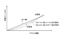
この場合には、図7に示すように、アクセル開度が同じ条件であるときに、符号201で示す標準変速段(N段)の場合に比べて、符号202で示す低速段(N−1段)の場合には、スロットル開度が小さくなるように電子スロットル特性を変更する。なお、変速段が低速段(N−1段)である場合には、上記のように、運転指向がノーマル走行指向である場合(符号202−1)に比べて、スポーツ走行指向である場合(符号202−2)には、スロットル開度が大きくなるように、電子スロットル特性を変更する。なお、ここでは、低速段は、(N−1)段として説明したが、(N−2)段についても同様に考えることができる(図8についても同様)。 In this case, as shown in FIG. 7, when the accelerator opening is the same, the low speed stage (N−1) shown by reference numeral 202 is compared with the standard speed stage (N stage) shown by reference numeral 201. Stage), the electronic throttle characteristic is changed so that the throttle opening becomes smaller. In the case where the gear position is the low speed stage (N-1 stage), as described above, the case where the driving direction is the sports driving direction as compared with the case where the driving direction is the normal driving direction (reference numeral 202-1) ( Reference numeral 202-2) changes the electronic throttle characteristic so that the throttle opening becomes large. Here, the low speed stage has been described as the (N-1) stage, but the (N-2) stage can be considered similarly (the same applies to FIG. 8).
次に、図8を参照して、変速段が標準変速段(N段)よりも低速段(N−1段)であるときの過渡特性及び効果の一例について説明する。 Next, with reference to FIG. 8, an example of transient characteristics and effects when the shift speed is lower (N-1) than the standard shift (N) will be described.
コーナの脱出時やコーナリング中などで運転者が加速を望んでアクセルを踏んだときには、ステップS70で変更された電子スロットル特性に基づいて、スロットル開度が決定される。図8は、あるアクセル開度(パーシャル開度)A(符号407)であるときの低速段(N−1段)の場合のスロットル開度と車両加速度を、標準変速段(N段)の場合と比較しつつ説明するための図である。符号407で示す実線は、標準変速段(N段)の場合と低速段(N−1段)の場合で同一のアクセル開度(パーシャル開度)Aであることを示している。
When the driver steps on the accelerator while accelerating the corner or during cornering, the throttle opening is determined based on the electronic throttle characteristic changed in step S70. FIG. 8 shows the throttle opening and vehicle acceleration in the case of a low speed (N-1) at a certain accelerator opening (partial opening) A (reference 407) in the case of a standard gear (N). It is a figure for demonstrating comparing with. A solid line denoted by
符号301で示す実線は、標準変速段(N段)の場合の車両加速度を示している。符号302で示す一点鎖線は、低速段(N−1段)において電子スロットル特性の変更後の場合の車両加速度を示している。符号303で示す破線は、低速段(N−1段)において電子スロットル特性が変更されない場合(従来技術)の車両加速度を示している。符号501で示す実線は、標準変速段(N段)の場合と低速段(N−1段)において電子スロットル特性が変更されない場合(従来技術)のスロットル開度を示している。符号502で示す一点鎖線は、低速段(N−1段)において電子スロットル特性の変更後の場合のスロットル開度を示している。
A solid line denoted by reference numeral 301 indicates the vehicle acceleration in the case of the standard shift speed (N speed). A one-dot chain line indicated by reference numeral 302 indicates the vehicle acceleration after the electronic throttle characteristic is changed at the low speed stage (N-1 stage). A broken line denoted by reference numeral 303 indicates the vehicle acceleration when the electronic throttle characteristic is not changed at the low speed stage (N-1 stage) (prior art). A solid line denoted by
まず、本実施形態における電子スロットル特性の変更が行われない場合(従来技術)、即ち、符号407で示すアクセル開度に対して、符号501で示すスロットル開度となる場合について説明する。低速段(N−1段)の場合には、標準変速段(N段)の場合に比べて、エンジントルクTeが減少する影響よりもギヤ比の係数が増加する影響をより大きく受けて、アクセル開度が開度A407であるとき、車両加速度が相対的に大きくなる(符号303と符号301参照)。この結果、行き先変速段が低速段(N−1段)であることによって、加速性能が過大となることにより、運転者は違和感を感じる場合がある。
First, a case where the electronic throttle characteristic is not changed in the present embodiment (conventional technology), that is, a case where the throttle opening indicated by
そこで、本実施形態では、符号407で示すアクセル開度に対して、符号502で示すスロットル開度となるように電子スロットル特性の変更を行い(ステップS70、図7参照)、低速段(N−1段)の場合の車両加速度を従来に比べて低減させる(符号303→符号302)。これにより、低速段(N−1段)の場合の車両加速度302を標準変速段(N段)の場合の車両加速度301に近づけることができ、行き先変速段によって、加速性能が異なることにより生じる運転者の違和感を抑制することができる。 Therefore, in the present embodiment, the electronic throttle characteristic is changed so that the throttle opening indicated by reference numeral 502 becomes the throttle opening indicated by reference numeral 407 (step S70, see FIG. 7), and the low speed stage (N− The vehicle acceleration in the case of the first stage is reduced as compared with the conventional case (reference numeral 303 → reference numeral 302). As a result, the vehicle acceleration 302 in the low speed stage (N-1 stage) can be brought close to the vehicle acceleration 301 in the standard speed stage (N stage), and driving caused by the acceleration performance being different depending on the destination gear stage. A person's discomfort can be suppressed.
次に、図9を参照して、変速段が標準変速段(N段)よりも高速段(N+1段)であるときの電子スロットル特性の一例について説明する。即ち、図9は、上記例とは反対に、標準変速段が3速(N段)であり、行き先変速段が4速(N+1段)である場合に対応している。 Next, an example of the electronic throttle characteristic when the shift speed is higher (N + 1) than the standard shift (N) will be described with reference to FIG. That is, FIG. 9 corresponds to the case where the standard shift speed is the third speed (N speed) and the destination shift speed is the fourth speed (N + 1 speed) contrary to the above example.
変速段が標準変速段(N段)よりも高速段(N+1段)であるときには、上記ステップS70(上記ステップS71〜ステップS76)の結果、図9に示す電子スロットル特性に変更される。なお、図9では、変速段が標準変速段(N段)である場合に比べて高速段(N+1段)である場合には、エンジントルクTeの増加分による影響が相対的に小さく、ギヤ比の係数の減少変化分による影響が相対的に大きく、出力トルクToは減少するケースについて説明する(図10についても同様)。 When the shift speed is higher (N + 1) than the standard shift speed (N), the electronic throttle characteristics shown in FIG. 9 are changed as a result of step S70 (steps S71 to S76). In FIG. 9, when the shift speed is the high speed stage (N + 1 stage) compared to the standard speed stage (N stage), the influence of the increase in the engine torque Te is relatively small, and the gear ratio An explanation will be given of a case where the output torque To decreases due to a relatively large influence due to the decrease change of the coefficient (the same applies to FIG. 10).
この場合には、図9に示すように、アクセル開度が同じ条件であるときに、符号201で示す標準変速段(N段)の場合に比べて、符号203で示す高速段(N+1段)の場合には、スロットル開度が大きくなるように電子スロットル特性を変更する。なお、変速段が高速段(N+1段)である場合には、運転指向がノーマル走行指向である場合(符号203−1)に比べて、スポーツ走行指向である場合(符号203−2)には、スロットル開度が大きくなるように、電子スロットル特性を変更する。なお、ここでは、高速段は、(N+1)段として説明したが、(N+2)段以降についても同様に考えることができる(図10についても同様)。 In this case, as shown in FIG. 9, when the accelerator opening is the same condition, the high speed stage (N + 1 stage) indicated by reference numeral 203 is compared to the case of the standard shift stage (N stage) indicated by reference numeral 201. In this case, the electronic throttle characteristic is changed so that the throttle opening becomes large. In the case where the gear stage is the high speed stage (N + 1 stage), when the driving direction is the sport driving direction (reference numeral 203-2), compared to the case where the driving direction is the normal driving direction (reference numeral 203-1). The electronic throttle characteristics are changed so that the throttle opening becomes large. Here, the high-speed stage has been described as the (N + 1) stage, but the same can be applied to the (N + 2) and subsequent stages (the same applies to FIG. 10).
次に、図10を参照して、変速段が標準変速段(N段)よりも高速段(N+1段)であるときの過渡特性及び効果の一例について説明する。 Next, with reference to FIG. 10, an example of transient characteristics and effects when the shift speed is higher (N + 1) than the standard shift (N) will be described.
図10は、あるアクセル開度(パーシャル開度)A(符号409)であるときの高速段(N+1段)の場合のスロットル開度と車両加速度を、標準変速段(N段)の場合と比較しつつ説明するための図である。符号409で示す実線は、標準変速段(N段)の場合と高速段(N+1段)の場合で同一のアクセル開度(パーシャル開度)Aであることを示している。
FIG. 10 compares the throttle opening and vehicle acceleration at the high speed stage (N + 1 stage) when the accelerator opening degree (partial opening degree) A (reference numeral 409) is compared with the case of the standard shift stage (N stage). It is a figure for demonstrating, however. A solid line denoted by
符号304で示す実線は、標準変速段(N段)の場合の車両加速度を示している。符号305で示す一点鎖線は、高速段(N+1段)において電子スロットル特性の変更後の場合の車両加速度を示している。符号306で示す破線は、高速段(N+1段)において電子スロットル特性が変更されない場合(従来技術)の車両加速度を示している。符号503で示す実線は、標準変速段(N段)の場合と高速段(N+1段)において電子スロットル特性が変更されない場合(従来技術)のスロットル開度を示している。符号504で示す一点鎖線は、高速段(N+1段)において電子スロットル特性の変更後の場合のスロットル開度を示している。
A solid line denoted by reference numeral 304 indicates the vehicle acceleration in the case of the standard shift speed (N speed). A one-dot chain line indicated by reference numeral 305 indicates the vehicle acceleration after the electronic throttle characteristic is changed at the high speed stage (N + 1 stage). A broken line indicated by reference numeral 306 indicates the vehicle acceleration when the electronic throttle characteristic is not changed at the high speed stage (N + 1 stage) (prior art). A solid line denoted by reference numeral 503 indicates the throttle opening when the electronic throttle characteristic is not changed (prior art) in the case of the standard speed (N) and the high speed (N + 1). A one-dot chain line indicated by
最初に、本実施形態における電子スロットル特性の変更が行われない場合(従来技術)、即ち、符号409で示すアクセル開度に対して、符号503で示すスロットル開度となる場合について説明する。高速段(N+1段)の場合には、標準変速段(N段)の場合に比べて、エンジントルクTeが増大する影響よりもギヤ比の係数が減少する影響をより大きく受けて、アクセル開度が開度A409であるとき、車両加速度が相対的に小さくなる(符号306と符号304参照)。この結果、行き先変速段が高速段(N+1段)であることによって、加速性能が過小となることにより、運転者は違和感を感じる場合がある。
First, the case where the electronic throttle characteristic is not changed in the present embodiment (conventional technology), that is, the case where the throttle opening indicated by reference numeral 503 is obtained with respect to the accelerator opening indicated by
そこで、本実施形態では、符号409で示すアクセル開度に対して、符号504で示すスロットル開度となるように電子スロットル特性の変更を行い(ステップS70、図9参照)、高速段(N+1段)の場合の車両加速度を従来に比べて増大させる(符号306→符号305)。これにより、高速段(N+1段)の場合の車両加速度305を標準変速段(N段)の場合の車両加速度304に近づけることができ、行き先変速段によって、加速性能が異なることにより生じる運転者の違和感を抑制することができる。
Therefore, in the present embodiment, the electronic throttle characteristic is changed so that the throttle opening indicated by
(第1実施形態の第1変形例)
上記第1実施形態において、電子スロットル特性(アクセル開度と電子スロットルバルブ43の開度との関係)は、図5のステップS71〜ステップS76に示すように逐次計算の結果として求められたが、予めマップデータとして、図7や図9のような特性をROM133に登録しておくことができる。この場合、図7や図9のような特性は、更に、エンジン回転数によって、補正されることができる。
(First modification of the first embodiment)
In the first embodiment, the electronic throttle characteristics (the relationship between the accelerator opening and the opening of the electronic throttle valve 43) are obtained as a result of the sequential calculation as shown in steps S71 to S76 in FIG. Characteristics as shown in FIGS. 7 and 9 can be registered in advance in the
(第1実施形態の第2変形例)
上記第1実施形態では、変速点制御が行なわれ(図1のステップS40−Y)、変速指令に係る行き先変速段が標準変速段(N段)と異なる場合(ステップS60−Y)に電子スロットル特性が変更された(ステップS70)が、本変形例では、更に、変速点制御が行なわれない場合(ステップS40−N)にも電子スロットル特性が変更されることができる(図1には図示せず)。
(Second modification of the first embodiment)
In the first embodiment, shift point control is performed (step S40-Y in FIG. 1), and the electronic throttle is operated when the destination shift stage related to the shift command is different from the standard shift stage (N stage) (step S60-Y). Although the characteristic has been changed (step S70), in this modification, the electronic throttle characteristic can also be changed when the shift point control is not performed (step S40-N) (FIG. Not shown).
例えば、アクセル開度が全閉とされたとき(ステップS10−Y)に6速で走行しており、必要減速度の計算結果(ステップS30)に基づいて、変速点制御の要否判断が行われた結果、制御不要と判定され(ステップS40−N)、6速のままコーナに進入していった場合に、同じ車速で同じアクセル開度のときに上記標準変速段(N段)による出力トルクと等しい又は近い出力トルクが得られるように、電子スロットル特性が変更されることができる。 For example, when the accelerator opening is fully closed (step S10-Y), the vehicle is traveling at the sixth speed, and whether or not the shift point control is necessary is determined based on the calculation result of the required deceleration (step S30). As a result, when it is determined that control is unnecessary (step S40-N) and the vehicle enters the corner with the sixth speed, the output from the standard gear stage (N stage) at the same vehicle speed and the same accelerator opening degree. The electronic throttle characteristic can be changed so that an output torque equal to or close to the torque is obtained.
(第1実施形態の第3変形例)
上記第1実施形態において、コーナ制御は、有段の自動変速機10の変速段の制御によって行なわれるとして説明したが、これに代えて、CVTの変速比の制御が行われることができる。CVTの場合、コーナリング中であるとの旋回判定が行われた時点やタイヤの滑りが有ると判定された時点において、変速が停止されるようにする。
(Third Modification of First Embodiment)
In the first embodiment, the corner control is described as being performed by controlling the gear position of the stepped
(第1実施形態の第4変形例)
上記第1実施形態において、コーナ制御は、自動変速機の変速制御のみによって行なわれたが、自動変速機とブレーキの協調制御により行なわれることができる。この場合、自動変速機10の変速制御のみならず、ブレーキ装置200のフィードバック制御がブレーキ制御回路230により実行される。ブレーキのフィードバック制御とは、目標減速度(必要減速度401)と車両の実減速度との偏差に応じてブレーキ力を制御することを意味する。
(Fourth modification of the first embodiment)
In the first embodiment, the corner control is performed only by the shift control of the automatic transmission, but can be performed by the cooperative control of the automatic transmission and the brake. In this case, not only the shift control of the
ブレーキのフィードバック制御は、ダウンシフト指令が出力された場所a又はbにて開始される。即ち、必要減速度401を示す信号がブレーキ制動力信号SG1として制御回路130からブレーキ制動力信号線L1を介してブレーキ制御回路230に出力される。ブレーキ制御回路230は、制御回路130から入力したブレーキ制動力信号SG1に基づいて、ブレーキ制御信号SG2を生成し、そのブレーキ制御信号SG2を油圧制御回路220に出力する。
The brake feedback control is started at the location a or b where the downshift command is output. That is, a signal indicating the required
油圧制御回路220は、ブレーキ制御信号SG2に基づいて、制動装置208、209、210、211に供給する油圧を制御することで、ブレーキ制御信号SG2に含まれる指示通りのブレーキ力(ブレーキ制御量)を発生させる。
The
ブレーキ装置200のフィードバック制御において、目標値は必要減速度401であり、制御量は車両の実減速度であり、制御対象はブレーキ(制動装置208、209、210、211)であり、操作量はブレーキ制御量であり、外乱は主として自動変速機10の変速による減速度である。車両の実減速度は、加速度センサ90等により検出される。
In the feedback control of the
即ち、ブレーキ装置200では、車両の実減速度が必要減速度401となるように、ブレーキ制動力(ブレーキ制御量)が制御される。即ち、ブレーキ制御量は、車両に必要減速度401を生じさせるに際して、自動変速機10の変速による減速度では不足する分の減速度を生じさせるように設定される。
That is, in the
なお、上記第4変形例におけるブレーキ制御は、上記ブレーキに代えて、パワートレーン系に設けたMG装置による回生ブレーキなどの他の、車両に制動力を生じさせる制動装置を用いても可能である。 The brake control in the fourth modified example can be performed by using a braking device that generates braking force on the vehicle, such as a regenerative braking by an MG device provided in the power train system, instead of the brake. .
(第1実施形態の第5変形例)
上記第1実施形態では、コーナの大きさやコーナまでの距離に基づいてダウンシフト制御(コーナ制御)が行なわれたときに(図1のステップS40−Y)、その行き先変速段が標準変速段(N段)と異なる場合(ステップS60−Y)には、同じ車速でかつ同じアクセル開度で標準変速段(N段)により得られる出力トルクと等しい又は近い値が行き先変速段での出力トルクとして得られるように、電子スロットル特性を変更するものであった。
(Fifth Modification of First Embodiment)
In the first embodiment, when downshift control (corner control) is performed based on the size of the corner and the distance to the corner (step S40-Y in FIG. 1), the destination gear stage is the standard gear stage ( When it is different from (N stage) (step S60-Y), a value equal to or close to the output torque obtained by the standard shift stage (N stage) at the same vehicle speed and the same accelerator opening is obtained as the output torque at the destination shift stage. As a result, the electronic throttle characteristics were changed.
これに対して、本変形例では、道路の勾配に基づいて行う減速制御(登降坂制御)や車両前方の車両との車間距離に基づく制御(追従制御)にも上記実施形態を適用することができる。即ち、登降坂制御や追従制御として、ダウンシフト制御が行なわれるときに、その行き先変速段が標準変速段(N段)と異なる場合には、同じ車速でかつ同じアクセル開度で標準変速段(N段)により得られる出力トルクと等しい又は近い値が行き先変速段での出力トルクとして得られるように、電子スロットル特性を変更することができる。 On the other hand, in the present modification, the above embodiment can also be applied to deceleration control (uphill / downhill control) performed based on the road gradient and control (follow-up control) based on the inter-vehicle distance from the vehicle ahead of the vehicle. it can. That is, when downshift control is performed as uphill / downhill control or follow-up control, if the destination shift stage is different from the standard shift stage (N stage), the standard shift stage with the same vehicle speed and the same accelerator opening ( The electronic throttle characteristic can be changed so that a value equal to or close to the output torque obtained by the (N stage) is obtained as the output torque at the destination gear stage.
更に、上記においては、車両が減速すべき量を示す減速度は、減速加速度(G)を用いて説明したが、減速トルクをベースに制御を行うことも可能である。 Further, in the above description, the deceleration indicating the amount that the vehicle should decelerate has been described using the deceleration acceleration (G), but it is also possible to control based on the deceleration torque.
10 自動変速機
40 エンジン
90 加速度センサ
91 アクセル開度センサ
95 ナビゲーションシステム装置
114 スロットル開度センサ
116 エンジン回転数センサ
122 車速センサ
123 シフトポジションセンサ
130 制御回路
131 CPU
133 ROM
200 ブレーキ装置
201 標準変速段(N段)及び従来の低速段(N−1段)での電子スロットル特性
202−1 ノーマル走行指向での低速段(N−1段)での電子スロットル特性
202−2 スポーツ走行指向での低速段(N−1段)での電子スロットル特性
203−1 ノーマル走行指向での低速段(N+1段)での電子スロットル特性
203−2 スポーツ走行指向での低速段(N+1段)での電子スロットル特性
230 ブレーキ制御回路
301 標準変速段(N段)での車両加速度
302 低速段(N−1段)での車両加速度
303 従来の低速段(N−1段)での車両加速度
304 標準変速段(N段)での車両加速度
305 高速段(N+1段)での車両加速度
306 従来の高速段(N+1段)での車両加速度
401 必要減速度
402 コーナ
403 入口
405 コーナR
407 アクセル開度
409 アクセル開度
501 標準変速段(N段)及び従来の低速段(N−1段)でのスロットル開度
502 低速段(N−1段)でのスロットル開度
503 標準変速段(N段)及び従来の高速段(N+1段)でのスロットル開度
504 高速段(N+1段)でのスロットル開度
a 地点
b 地点
Vreq 目標旋回車速
L 制御実施境界線
L1 ブレーキ制動力信号線
SG1 ブレーキ制動力信号
SG2 ブレーキ制御信号
Te エンジントルク
Ne エンジン回転数
DESCRIPTION OF
133 ROM
200 Brake Device 201 Electronic Throttle Characteristics at Standard Shift Stage (N Stage) and Conventional Low Speed Stage (N-1 Stage) 202-1 Electronic Throttle Characteristics at Low Speed Stage (N-1 Stage) for Normal Driving Direction 202- 2 Electronic throttle characteristics at low speed (N-1 stage) in sport driving direction 203-1 Electronic throttle characteristics at low speed (N + 1 stage) in normal driving direction 203-2 Low speed stage (N + 1) at sports driving direction Electronic throttle characteristics at the stage 230) Brake control circuit 301 Vehicle acceleration at the standard speed stage (N stage) 302 Vehicle acceleration at the low speed stage (N-1 stage) 303 Vehicle at the conventional low speed stage (N-1 stage) Acceleration 304 Vehicle acceleration at standard gear stage (N stage) 305 Vehicle acceleration at high speed stage (N + 1 stage) 306 Vehicle acceleration at conventional high speed stage (N + 1 stage) 401
407 Accelerator opening 409
Claims (10)
前記変速機の制御が行われた後の変速段又は変速比に応じて、電子スロットルの制御が行なわれる
ことを特徴とする車両用駆動力制御装置。 A vehicle driving force control device that controls at least a transmission based on at least one of a traveling state and a traveling environment of a vehicle,
The vehicle driving force control apparatus according to claim 1, wherein the electronic throttle is controlled in accordance with a gear stage or a gear ratio after the transmission is controlled.
前記電子スロットルの制御は、前記変速機の制御が行われた後の変速段又は変速比に応じた前記車両の出力トルクの変化が小さくなるように行われる
ことを特徴とする車両用駆動力制御装置。 The vehicle driving force control device according to claim 1,
The electronic throttle control is performed so that a change in the output torque of the vehicle according to a gear stage or a gear ratio after the transmission is controlled is small. apparatus.
前記電子スロットルの制御は、予め設定された変速段又は変速比による前記車両の加速特性に近づくように行われる
ことを特徴とする車両用駆動力制御装置。 In the vehicle driving force control device according to claim 1 or 2,
The control of the electronic throttle is performed so as to approach the acceleration characteristics of the vehicle by a preset gear position or gear ratio.
前記変速機の制御が行われた後の変速段又は変速比により生じる前記車両の出力トルクが、予め設定された変速段又は変速比により生じる前記出力トルクに比べて小さいときには、前記電子スロットルを開く制御が行われる
ことを特徴とする車両用駆動力制御装置。 In the vehicle driving force control device according to any one of claims 1 to 3,
The electronic throttle is opened when the output torque of the vehicle generated by the speed or speed ratio after the transmission is controlled is smaller than the output torque generated by a preset speed or speed ratio. A vehicle driving force control device characterized in that control is performed.
前記変速機の制御が行われた後の変速段又は変速比により生じる前記車両の出力トルクが、予め設定された変速段又は変速比により生じる前記出力トルクに比べて大きいときには、前記電子スロットルを閉じる制御が行われる
ことを特徴とする車両用駆動力制御装置。 In the vehicle driving force control device according to any one of claims 1 to 4,
The electronic throttle is closed when the output torque of the vehicle generated by the shift speed or gear ratio after the transmission is controlled is larger than the output torque generated by a preset shift speed or gear ratio. A vehicle driving force control device characterized in that control is performed.
前記電子スロットルの制御は、エンジン回転速度に基づいて行われる
ことを特徴とする車両用駆動力制御装置。 In the vehicle driving force control device according to any one of claims 1 to 5,
The electronic throttle control is performed based on an engine rotation speed.
前記電子スロットルの制御は、運転指向に基づいて行われる
ことを特徴とする車両用駆動力制御装置。 In the vehicle driving force control device according to any one of claims 1 to 6,
The vehicle driving force control device is characterized in that the electronic throttle is controlled based on driving orientation.
ことを特徴とする車両用駆動力制御装置。 The vehicle drive force control device according to any one of claims 1 to 7, wherein the control of the electronic throttle is ended when an upshift of the transmission is performed. Force control device.
前記変速機の制御が行われた後の変速段又は変速比に応じた前記車両の出力トルクの変化を小さくさせる制御が行われる
ことを特徴とする車両用駆動力制御装置。 A vehicle driving force control device that controls at least a transmission based on at least one of a traveling state and a traveling environment of a vehicle,
A vehicle driving force control device characterized in that control is performed to reduce a change in output torque of the vehicle in accordance with a gear stage or a gear ratio after the transmission is controlled.
前記車両の走行状態には、前記車両と前記車両よりも先行している先行車との間の車間距離の状況が含まれ、前記走行環境には、前記車両の前方のコーナの大きさ及び路面勾配の少なくともいずれか一方が含まれる
ことを特徴とする車両用駆動力制御装置。
In the vehicle driving force control device according to any one of claims 1 to 9,
The traveling state of the vehicle includes a situation of an inter-vehicle distance between the vehicle and a preceding vehicle preceding the vehicle, and the traveling environment includes a size of a corner and a road surface in front of the vehicle. A vehicle driving force control device including at least one of gradients.
Priority Applications (1)
| Application Number | Priority Date | Filing Date | Title |
|---|---|---|---|
| JP2005132635A JP2006307768A (en) | 2005-04-28 | 2005-04-28 | Driving force controller for vehicle |
Applications Claiming Priority (1)
| Application Number | Priority Date | Filing Date | Title |
|---|---|---|---|
| JP2005132635A JP2006307768A (en) | 2005-04-28 | 2005-04-28 | Driving force controller for vehicle |
Publications (1)
| Publication Number | Publication Date |
|---|---|
| JP2006307768A true JP2006307768A (en) | 2006-11-09 |
Family
ID=37474934
Family Applications (1)
| Application Number | Title | Priority Date | Filing Date |
|---|---|---|---|
| JP2005132635A Pending JP2006307768A (en) | 2005-04-28 | 2005-04-28 | Driving force controller for vehicle |
Country Status (1)
| Country | Link |
|---|---|
| JP (1) | JP2006307768A (en) |
Cited By (3)
| Publication number | Priority date | Publication date | Assignee | Title |
|---|---|---|---|---|
| JP2008309230A (en) * | 2007-06-13 | 2008-12-25 | Nissan Motor Co Ltd | Control device during speed-change of vehicle |
| JP2009002282A (en) * | 2007-06-22 | 2009-01-08 | Toyota Motor Corp | Braking force control device |
| JP2009287480A (en) * | 2008-05-30 | 2009-12-10 | Kawasaki Heavy Ind Ltd | Travel control device, and vehicle |
-
2005
- 2005-04-28 JP JP2005132635A patent/JP2006307768A/en active Pending
Cited By (4)
| Publication number | Priority date | Publication date | Assignee | Title |
|---|---|---|---|---|
| JP2008309230A (en) * | 2007-06-13 | 2008-12-25 | Nissan Motor Co Ltd | Control device during speed-change of vehicle |
| US8016723B2 (en) | 2007-06-13 | 2011-09-13 | Nissan Motor Co., Ltd. | Vehicle engine control apparatus |
| JP2009002282A (en) * | 2007-06-22 | 2009-01-08 | Toyota Motor Corp | Braking force control device |
| JP2009287480A (en) * | 2008-05-30 | 2009-12-10 | Kawasaki Heavy Ind Ltd | Travel control device, and vehicle |
Similar Documents
| Publication | Publication Date | Title |
|---|---|---|
| JP4434101B2 (en) | Vehicle driving force control device | |
| JP2005297611A (en) | Deceleration control device of vehicle | |
| JP2005226670A (en) | Deceleration control device for vehicle | |
| JP2006038078A (en) | Deceleration control device for vehicle | |
| JP2007139090A (en) | Travel control device for vehicle | |
| JP2006307768A (en) | Driving force controller for vehicle | |
| JP2007146998A (en) | Transmission control device | |
| JP2005193794A (en) | Vehicular deceleration control device | |
| JP2006015952A (en) | Deceleration control device for vehicle | |
| JP2006137392A (en) | Vehicle deceleration controller | |
| JP4581614B2 (en) | Transmission control device | |
| JP2007071230A (en) | Driving force controller for vehicle | |
| JP2007107705A (en) | Driving force control device for vehicle | |
| JP2007170444A (en) | Vehicle driving force control device | |
| JP4843967B2 (en) | Vehicle deceleration control device | |
| JP4617995B2 (en) | Vehicle driving force control device | |
| JP2006213133A (en) | Deceleration control device for vehicle | |
| JP4982969B2 (en) | Vehicle driving force control device | |
| JP2007246039A (en) | Driving force controller for vehicle | |
| JP5028771B2 (en) | Vehicle driving force control device | |
| JP4946021B2 (en) | Transmission control device | |
| JP4816112B2 (en) | Vehicle driving force control device | |
| JP2005308096A (en) | Control device for transmission | |
| JP2008267587A (en) | Vehicular braking/driving force control device, and vehicular braking/driving force control method | |
| JP2007247866A (en) | Drive force control device for vehicle |