JP2006307606A - Structural material such as wooden column or beam - Google Patents
Structural material such as wooden column or beam Download PDFInfo
- Publication number
- JP2006307606A JP2006307606A JP2005134683A JP2005134683A JP2006307606A JP 2006307606 A JP2006307606 A JP 2006307606A JP 2005134683 A JP2005134683 A JP 2005134683A JP 2005134683 A JP2005134683 A JP 2005134683A JP 2006307606 A JP2006307606 A JP 2006307606A
- Authority
- JP
- Japan
- Prior art keywords
- dowel
- wood
- dowels
- square
- structural material
- Prior art date
- Legal status (The legal status is an assumption and is not a legal conclusion. Google has not performed a legal analysis and makes no representation as to the accuracy of the status listed.)
- Pending
Links
Images


Landscapes
- Rod-Shaped Construction Members (AREA)
Abstract
Description
本発明は、適宜の角材又は板状材が重ねられつつダボにて傾斜角度を有して前記角材又は板状材相互が結合された構成とし、特に、接着剤(糊)を使うことなく、強固且つ耐久性に優れ、環境などに良好な木質系の柱又は梁等の構造材に関する。 The present invention has a configuration in which the square or plate-like materials are combined with each other with an inclination angle with a dowel while an appropriate square or plate-like material is stacked, and in particular, without using an adhesive (glue), The present invention relates to a structural material such as a wooden column or beam that is strong and excellent in durability and good for the environment.
従来技術としては、特許文献1に示すように、複数の単板を積層した合板、該合板を使用した合板パネル、及び該合板の製造方法に関し、特に、建築土木用の構造用合板又は合板パネルとして開示されている。また、特許文献2に示すように、既成積層木材ユニットも存在している。
As a prior art, as shown in
わが国では、木質系の柱又は梁としての構造材としては、好ましくは、樹齢数十年の松、杉などの樹木が使用されているが、その数は年々減少している。また、これよりもか細い樹木の間伐材としての板厚のある板状体、又は小径木の角材、又は間伐材の板厚を薄くした等の板状材は多く存在している。そこで、合板としての柱又は梁等の構造材も多数存在しているが、接着剤を使ったとしても永年使用によって強度的に問題が出ている。 In Japan, trees such as pine and cedar, which are several decades old, are preferably used as a structural material as a wooden column or beam, but the number is decreasing year by year. In addition, there are many plate-like materials such as a thin plate having a thickness as a thinning material of a tree thinner than this, or a square wood having a small diameter, or a thinning material having a thin thickness. Therefore, there are many structural materials such as columns or beams as plywood, but even if an adhesive is used, there is a problem in strength due to long-term use.
また、積層間の接着剤(糊)の存在により、燃やすときに、ダイオキシンが発生するとのことで、環境上問題視されている。また、その接着剤(糊)の存在は、シックハウス症候群の原因とも言われ、健康問題としても問題視されている。
しかるに、特許文献1では、ダボ方式で接着剤(糊)を使う接合では、永年使用後では、必ずしも強度性が得られなかった。このため、本発明が解決しようとする課題(技術的課題又は目的等)は、接着剤(糊)を使うことなく傾斜ダボを使うことで、強固且つ耐久性に優れ、環境などに良好な木質系の柱又は梁等の構造材を実現することである。
However, in
そこで、発明者は上記課題を解決すべく鋭意,研究を重ねた結果、請求項1の発明を、何らの接着剤を使うことなく異なる角材又は板状材等の木材が重ねられ、該木材からなる複数のダボにて結合され、且つ該ダボは適宜な傾斜角度を有して設けられてなることを特徴とする木質系の柱又は梁等の構造材としたことにより、前記課題を解決したものである。また、請求項 2の発明においては、前述の構成において、前記木材は、厚み又は太さのある角材からなり、二本が重ねられてなることを特徴とする木質系の柱又は梁等の構造材としたことにより、前記課題を解決したものである。
Therefore, as a result of intensive researches to solve the above problems, the inventor made the invention of
請求項3の発明においては、前述の構成において、前記木材は、厚さが比較的薄く形成された角材からなり、3枚以上が重ねられてなることを特徴とする木質系の柱又は梁等の構造材としたことにより、前記課題を解決したものである。また、請求項4の発明においては、前述の構成において、前記ダボの傾斜角度は、前記木材の長手方向に適宜な角度傾斜してなることを特徴とする木質系の柱又は梁等の構造材としたことにより、前記課題を解決したものである。 According to a third aspect of the present invention, in the above-mentioned configuration, the wood is made of a square material having a relatively thin thickness, and is made of three or more stacked wooden columns or beams, etc. Thus, the above-mentioned problems are solved. According to a fourth aspect of the present invention, in the above-described configuration, the dowel is inclined at an appropriate angle in the longitudinal direction of the wood, such as a wooden column or beam. Thus, the above-mentioned problem is solved.
また、請求項5の発明においては、前述の構成において、前記ダボの傾斜角度は、前記木材の幅方向にも適宜な角度傾斜してなることを特徴とする木質系の柱又は梁等の構造材としたことにより、前記課題を解決したものである。また、請求項6の発明においては、前述の構成において、前記ダボの傾斜角度は、約3°乃至約30°に形成されてなることを特徴とする木質系の柱又は梁等の構造材としたことにより、前記課題を解決したものである。さらに、請求項7の発明においては、前述の構成において、前記ダボが少なくとも3本以上設けられているときに、一部を垂直に設けてなることを特徴とする木質系の柱又は梁等の構造材としたことにより、前記課題を解決したものである。 According to a fifth aspect of the present invention, in the above-described configuration, the dowels are inclined at an appropriate angle also in the width direction of the wood, such as a wooden column or beam. By using a material, the above-mentioned problems are solved. According to a sixth aspect of the present invention, in the above-described configuration, the dowel is formed with an inclination angle of about 3 ° to about 30 °, and a structural material such as a wooden column or beam, As a result, the above-described problems have been solved. Furthermore, in the invention according to claim 7, in the above-described configuration, when at least three dowels are provided, a part of the wooden column or beam is provided vertically, etc. By using a structural material, the above-mentioned problems are solved.
請求項1の発明においては、強度を有した結合ができ、接着剤を使わないことから、仮に焼却してもダイオキシンの発生もなく、近年問題視されているシックハウス症候群にならず、さらにダボの傾斜設置にて頗る強固にできる利点がある。また、請求項2の発明では、間伐材としての角材を有効利用でき、国内の木材産業に多大なる貢献ができる。また、請求項の発明では、間伐材から取った角材を有効利用でき、これはまた国内の木材産業に貢献ができるものである。請求項4の発明では、十分に強固な強度に結合できる。また、請求項5の発明においては、さらに強固な結合ができる。また、請求項6の発明では、請求項4の発明と同等な効果を奏する。また、請求項7の発明においては、請求項1の発明と同等な効果を奏するものである。
In the invention of
以下、本発明の実施形態について図面に基づいて説明すると、図1乃至図2は第1実施形態であって、2本の厚み又は太さのある間伐材としての角材1,1にて構成されている。該角材1,1の長手方向の相互の接合面が接触して、複数のダボ3にて結合されている。その接合面には何らの接着剤も使用されない。該ダボ3は、任意の角度に傾斜されたダボ穴4に堅めに挿入されて結合されている[図2(B)参照]。該ダボ3による結合について詳述する。
Hereinafter, the embodiment of the present invention will be described with reference to the drawings. FIG. 1 and FIG. 2 are the first embodiment, and are composed of two thinned or thick
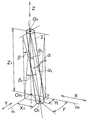
前記角材1の長手方向をX方向とし、該角材1,1が結合された高さ方向をZ方向とし、前記X方向とZ方向とに直交する方向をY方向とする。すなわち、該Y方向は、前記X方向に直交しつつ前記角材1,1の結合面に平行な方向とする。すると、前記ダボ3及びダボ穴4の傾斜角度としては、X方向から見て∠α[図2(A) 参照]で、Y方向から見て∠β[図2(C) 参照]で、Z方向から見て∠γ[図2(D) 参照]として構成されている。
The longitudinal direction of the
前記∠α、∠β及び∠γは、それぞれ任意の約2、3°から約30°の角度として構成されている。前記角材1などの木材では、該木材を構成する繊維は木の長手方向に配列されているため、この長手方向(X方向)への傾斜角度∠βは最低設けるものである。
さらに具体的には、図1の(ア)個所を拡大した図1(B)及び図2について説明すると、前記角材1の頂部面と同一面上であって、前記ダボ3頂部の真円の中心をO0とし、且つ前記角材1の底部面と同一面上であって、前記ダボ3底部の真円の中心をO1とし、前記O0点から下した垂線と前記角材1の底部面上の足をOnとし、該On点からX方向及びY方向に基準線m,nを引く。すると、X方向から見たOnO1は、線分Y1となり、Y方向から見たOnO1は、線分X1となる。
The ∠α, ∠β, and ∠γ are each configured as an arbitrary angle of about 2, 3 ° to about 30 °. In the wood such as the
More specifically, FIG. 1 (B) and FIG. 2 in which the portion (a) of FIG. 1 is enlarged will be described. The top of the
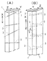
前記X方向から見た線分Y1は∠αとなる[図3(A)参照]。また、Y方向から見た線分X1は∠βとなる[図3(C)参照]。また、平面的に見た角度は、∠γである。このような結合は、図4(A)及び(B)に示すように、少なくとも2本の角材1,1が、X―Z面において、適宜な傾斜角度となるように、ダボ3が適宜の間隔をおいて複数形成されている。図4(A)では、一列にダボ3が設けられ、図4(B)の場合は、二列にダボ3が設けられている。また、図5(A)のように、長手方向に、ダボ3が1本、2本と交互に設けられることもある。これを平面的に見て、ダボ3の傾斜方向を矢印として簡略化すると、図5(B)に示す通りである。
Line Y 1 as viewed from the X direction is the ∠Arufa [FIG 3 (A) Reference. Further, the line segment X 1 as viewed from the Y direction is ∠Beta [FIG 3 (C) Reference. Further, the angle viewed in a plane is ∠γ. As shown in FIGS. 4 (A) and 4 (B), the
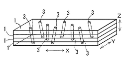
次に、本発明の第2実施形態を、図6及び図7に基づいて説明する。図6(A)に示すように、主として間伐材を使用する。この間伐材としての木材Aを扁平な板状材2として形成し、少なくとも、3枚以上(図6及び図7では、4枚)が重ねられ、この状態で、第1実施形態と同様に立体的に傾斜したダボ3が設けられている。この場合にも、図7に示すように、図5と同様にダボ3を配置させて結合している。また、ダボ3が、角材1,1を貫通している場合を貫通ダボといい、図1乃至図5及び図6(A)の場合である。また、一方向端が隠れた状態の場合を隠しダボといい、図6(B)の右側の場合である。外観を重視してダボ3を隠した面を表面として、構造物の柱又は梁に使用するものである。強度的には、貫通ダボも隠しダボであっても同等である。このように間伐材としての木材Aには、角材1と板状材2とが含まれる。前記木材Aには、無垢の間伐材が使用されることが多いが、これ以外の木質系部材を使用することもある。
Next, a second embodiment of the present invention will be described with reference to FIGS. As shown in FIG. 6A, thinned wood is mainly used. The wood A as the thinned material is formed as a flat plate-like material 2, and at least three or more (in FIG. 6 and FIG. 7, four) are stacked. An
前記ダボ3の材料としては、前記角材1又は板状材2等の木材Aよりも硬い材質の木材Aを使用するのが通常であるが、強度をそれほど要求されない場合には、前記木材Aと同一材を使用することもある。また、ダボ3の径は、前記ダボ穴4の内径よりも僅かに大きくして固く押し込むようにして前記木材A,A相互を結合する。通常、前記ダボ3の直径は、約10mm乃至約30mm程度で使用される。また、小型材の柱又は梁では10mm以下でも、大型材の柱又は梁では30mm以上でも使用されるものである。ダボ3が木材Aに圧迫密着するために、ダボ3材の含水率として、約15%以下、好ましくは約10%近くにして使用する。
As the material of the
また、前記角材1は、乾燥状態として、含水率として、約20%以下、好ましくは約15%程度を使用するものである。さらに、該角材1において、扁平な板材の場合は、板厚(Z方向)が、約30mm内外であって、幅(Y方向)が約100mm乃至約200mmをなし、長手方向(X方向)が、約100cm乃至約800cm程度の部材が使用される。ダボ3にて強固に結合されていれば、その数値には限定されない。
The
また、傾斜設置されたダボ3で結合された角材1,1についての強度を説明する。図8に示すように、角材1,1にダボ3の軸方向としてZ方向に全体の力Fが作用して、角材1,1を剥がすように作用した場合である。図8の上側のダボ3の立体角をθ1とする。該θ1は、図1の(ア)個所の∠α1と∠β1と∠γとで構成された立体角である。また、図8の下側のダボ3の立体角をθ2とする。これは、図1の(イ)個所の∠α2と∠β2と∠γとで構成された立体角である。また、図8の上側のダボ3に加わる分力をf1とし、図8の下側のダボ3に加わる分力をf2とする。説明を簡略化して、分力f1と分力f2との2本のダボ3で合力F(全体の力)とすると、f1cosθ1+f2cosθ2=剥がす合力となる。ここで、分力f1と分力f2の方向が異なることから、前記角材1が圧縮又は引張による外力にて変形しない場合には、剥がす力として作用しない。すなわち、角材1,1相互は結合状態を保持する。また、f1sinθ1+f2sinθ2=2本のダボ3のせん断力となる。このせん断力が、ダボ3の材質及び直径による強度性として保持される。
Moreover, the intensity | strength about the
以上のように、傾斜設置されたダボ3で結合された角材1,1は、何らの接着剤を使うことがなくても、角材1,1相互は強固な結合ができる。このように、接着剤を使わないことから、仮に焼却してもダイオキシンの発生もなく、近年問題視されているシックハウス症候群を確実に回避できるという大きな利点がある。特に、何らの接着剤を使わないことから安価に構成できつつ、強固にできるという極めて顕著な効果を奏する発明である。
As described above, the
なお、1本の木材に対して、前述した本発明と同様に、適宜の角度傾斜させたダボを複数設けて、縦て割れしやすい木材の弱点を補う目的にも利用できる。このことは、木材を構成する繊維は木の長手方向に配列されており、強度的に見れば木の太さ方向(直径方向)に多重積層構造である。過度のせん断力が繊維の流れ方向に働いたときには当然積層剥離が起こる。その剥離を防止するために、せん断力に対し直交方向に適宜の角度傾斜させたダボを複数打つ構成とするものである。 It should be noted that, similarly to the above-described present invention, a plurality of dowels inclined at an appropriate angle are provided for one piece of wood, and this can be used for the purpose of compensating for the weak points of wood that easily breaks vertically. This is because the fibers constituting the wood are arranged in the longitudinal direction of the tree, and in terms of strength, it has a multi-layered structure in the thickness direction (diameter direction) of the tree. When an excessive shear force is applied in the fiber flow direction, delamination naturally occurs. In order to prevent the peeling, a plurality of dowels that are inclined at an appropriate angle in the direction orthogonal to the shearing force are formed.
近時、間伐材の利用を如何にするかが問題視されていたが、本発明では、間伐材の利用可能性が極めて高く、国内の木材産業の救世主となるのみならず、国内の林業及び木材産業の発展に多大なる貢献ができるものである。ひいては、森林保全、環境保持に貢献できる。 Recently, there has been a problem of how to use thinned wood, but in the present invention, the possibility of using thinned wood is extremely high, not only becoming a savior of the domestic timber industry, but also domestic forestry and It can greatly contribute to the development of the timber industry. As a result, it can contribute to forest conservation and environmental preservation.
A…木材
1…角材
2…板状材
3…ダボ
4…ダボ穴
A ...
Claims (7)
7. A wooden column or beam according to claim 1, 2, 3, 4, 5 or 6, wherein when at least three dowels are provided, a part thereof is provided vertically. Structural material.
Priority Applications (1)
| Application Number | Priority Date | Filing Date | Title |
|---|---|---|---|
| JP2005134683A JP2006307606A (en) | 2005-05-02 | 2005-05-02 | Structural material such as wooden column or beam |
Applications Claiming Priority (1)
| Application Number | Priority Date | Filing Date | Title |
|---|---|---|---|
| JP2005134683A JP2006307606A (en) | 2005-05-02 | 2005-05-02 | Structural material such as wooden column or beam |
Publications (2)
| Publication Number | Publication Date |
|---|---|
| JP2006307606A true JP2006307606A (en) | 2006-11-09 |
| JP2006307606A5 JP2006307606A5 (en) | 2008-09-18 |
Family
ID=37474797
Family Applications (1)
| Application Number | Title | Priority Date | Filing Date |
|---|---|---|---|
| JP2005134683A Pending JP2006307606A (en) | 2005-05-02 | 2005-05-02 | Structural material such as wooden column or beam |
Country Status (1)
| Country | Link |
|---|---|
| JP (1) | JP2006307606A (en) |
Cited By (7)
| Publication number | Priority date | Publication date | Assignee | Title |
|---|---|---|---|---|
| KR100975338B1 (en) * | 2009-12-14 | 2010-08-12 | (주)대명가로등 | Method for manufacturing wooden pole |
| JP2016211327A (en) * | 2015-05-13 | 2016-12-15 | 株式会社大林組 | Joining structure and joining method between fire resistant construction material beam and concrete slab |
| JP2016211326A (en) * | 2015-05-13 | 2016-12-15 | 株式会社大林組 | Junction structure and method for column of fire-resisting construction material |
| JP2016211325A (en) * | 2015-05-13 | 2016-12-15 | 株式会社大林組 | Fire resistant construction material, manufacturing method for the same, joining structure for the same and joining method for the same |
| JP2016211328A (en) * | 2015-05-13 | 2016-12-15 | 株式会社大林組 | Junction structure and method between column and beam of fire-resisting construction material and joining structure of the same |
| JP7186983B1 (en) * | 2021-11-19 | 2022-12-12 | 株式会社長谷萬 | Wooden panel manufacturing method and wooden panel |
| RU222031U1 (en) * | 2023-07-04 | 2023-12-07 | Александр Михайлович Перфильев | GLUED BLOCK FROM WOOD WASTE (WOODEN BRICK) |
-
2005
- 2005-05-02 JP JP2005134683A patent/JP2006307606A/en active Pending
Cited By (7)
| Publication number | Priority date | Publication date | Assignee | Title |
|---|---|---|---|---|
| KR100975338B1 (en) * | 2009-12-14 | 2010-08-12 | (주)대명가로등 | Method for manufacturing wooden pole |
| JP2016211327A (en) * | 2015-05-13 | 2016-12-15 | 株式会社大林組 | Joining structure and joining method between fire resistant construction material beam and concrete slab |
| JP2016211326A (en) * | 2015-05-13 | 2016-12-15 | 株式会社大林組 | Junction structure and method for column of fire-resisting construction material |
| JP2016211325A (en) * | 2015-05-13 | 2016-12-15 | 株式会社大林組 | Fire resistant construction material, manufacturing method for the same, joining structure for the same and joining method for the same |
| JP2016211328A (en) * | 2015-05-13 | 2016-12-15 | 株式会社大林組 | Junction structure and method between column and beam of fire-resisting construction material and joining structure of the same |
| JP7186983B1 (en) * | 2021-11-19 | 2022-12-12 | 株式会社長谷萬 | Wooden panel manufacturing method and wooden panel |
| RU222031U1 (en) * | 2023-07-04 | 2023-12-07 | Александр Михайлович Перфильев | GLUED BLOCK FROM WOOD WASTE (WOODEN BRICK) |
Similar Documents
| Publication | Publication Date | Title |
|---|---|---|
| MY152609A (en) | Engineered wood building material with veneer composite core and vertical glue-line position | |
| JP2006307606A (en) | Structural material such as wooden column or beam | |
| JP2020513076A (en) | Building system with crossed structural boards | |
| JP4162675B2 (en) | Wooden construction materials | |
| JPWO2019074126A1 (en) | Multi-layer non-combustible wood | |
| JP2006307607A (en) | Woody wall body | |
| JP2006307606A5 (en) | ||
| JP2018178655A (en) | Roof truss face structure | |
| JP2014055406A (en) | Wooden beam | |
| US9434136B1 (en) | Dauer board | |
| JP2002364091A (en) | Outer wall structure | |
| JP3175606U (en) | Building materials | |
| JP2009000932A (en) | Glued laminated timber for structure | |
| JP2013181315A (en) | Batten cleat for ceiling board | |
| EP1811097A2 (en) | Building element | |
| CN114536484B (en) | Wood-nailed laminated wood and preparation method and application thereof | |
| JP4882392B2 (en) | Construction materials | |
| KR20090066398A (en) | Glulam for structure | |
| JP2007009437A (en) | Connecting structure for lumber, and structure for wooden building using the same | |
| JP3151928U (en) | Glulam | |
| JP2011080204A (en) | Wooden beam member | |
| JP3300316B2 (en) | Architectural board and wall foundation structure using the architectural board | |
| JP2022099684A (en) | Orthogonally-laminated plate using bamboo material | |
| JP6414261B2 (en) | Wood ramen moment resistance structure | |
| JP2002307409A (en) | Method for manufacturing glued laminated timber and glued laminated timber formed by the same |
Legal Events
| Date | Code | Title | Description |
|---|---|---|---|
| A621 | Written request for application examination |
Free format text: JAPANESE INTERMEDIATE CODE: A621 Effective date: 20080428 |
|
| A521 | Written amendment |
Effective date: 20080731 Free format text: JAPANESE INTERMEDIATE CODE: A523 |
|
| A871 | Explanation of circumstances concerning accelerated examination |
Free format text: JAPANESE INTERMEDIATE CODE: A871 Effective date: 20080731 |
|
| A975 | Report on accelerated examination |
Free format text: JAPANESE INTERMEDIATE CODE: A971005 Effective date: 20080821 |
|
| A131 | Notification of reasons for refusal |
Free format text: JAPANESE INTERMEDIATE CODE: A131 Effective date: 20080826 |
|
| A02 | Decision of refusal |
Free format text: JAPANESE INTERMEDIATE CODE: A02 Effective date: 20090113 |