JP2006307536A - Underfloor piping structure - Google Patents
Underfloor piping structure Download PDFInfo
- Publication number
- JP2006307536A JP2006307536A JP2005131379A JP2005131379A JP2006307536A JP 2006307536 A JP2006307536 A JP 2006307536A JP 2005131379 A JP2005131379 A JP 2005131379A JP 2005131379 A JP2005131379 A JP 2005131379A JP 2006307536 A JP2006307536 A JP 2006307536A
- Authority
- JP
- Japan
- Prior art keywords
- drainage
- pipe
- downstream
- header
- connection port
- Prior art date
- Legal status (The legal status is an assumption and is not a legal conclusion. Google has not performed a legal analysis and makes no representation as to the accuracy of the status listed.)
- Granted
Links
- 238000011144 upstream manufacturing Methods 0.000 claims abstract description 47
- 238000009423 ventilation Methods 0.000 claims abstract description 20
- XLYOFNOQVPJJNP-UHFFFAOYSA-N water Substances O XLYOFNOQVPJJNP-UHFFFAOYSA-N 0.000 abstract description 24
- 238000007789 sealing Methods 0.000 abstract description 11
- 239000002351 wastewater Substances 0.000 abstract description 7
- 230000000149 penetrating effect Effects 0.000 abstract description 2
- 210000002310 elbow joint Anatomy 0.000 description 11
- 235000013351 cheese Nutrition 0.000 description 6
- 239000004744 fabric Substances 0.000 description 6
- 238000003780 insertion Methods 0.000 description 6
- 230000037431 insertion Effects 0.000 description 6
- 229920003002 synthetic resin Polymers 0.000 description 5
- 239000000057 synthetic resin Substances 0.000 description 5
- 238000012856 packing Methods 0.000 description 4
- 239000000853 adhesive Substances 0.000 description 3
- 230000001070 adhesive effect Effects 0.000 description 3
- 230000035515 penetration Effects 0.000 description 3
- 239000002689 soil Substances 0.000 description 3
- 230000003247 decreasing effect Effects 0.000 description 2
- 230000001771 impaired effect Effects 0.000 description 2
- 238000007689 inspection Methods 0.000 description 2
- 210000003437 trachea Anatomy 0.000 description 2
- 230000000903 blocking effect Effects 0.000 description 1
- 238000010276 construction Methods 0.000 description 1
- 230000007423 decrease Effects 0.000 description 1
- 210000001503 joint Anatomy 0.000 description 1
- 230000002093 peripheral effect Effects 0.000 description 1
- 230000000630 rising effect Effects 0.000 description 1
Images


Abstract
Description
本発明は、排水ヘッダーを用いた集中一括排水システムの床下配管における負圧の発生をなくし、負圧による水設備のトラップの封水破壊を防止することができる床下配管構造に関する。 The present invention relates to an underfloor piping structure that eliminates the generation of negative pressure in the underfloor piping of a centralized collective drainage system that uses a drainage header, and can prevent the sealing failure of a water facility trap due to the negative pressure.
排水ヘッダーを用いた集中一括排水システムの床下配管においては、洗面台、台所、浴室、トイレなどの水設備から多量の排水が上流側排水管や排水枝管を通って排水ヘッダーに流入すると、排水ヘッダー内部の水位が上昇して下流側排水管の排水ヘッダー近傍部分が排水によって閉塞され、排水ヘッダーの内部や上流側排水管の内部や排水枝管の内部に負圧が発生して、水設備のトラップの封水破壊が生じやすいという問題があった。また、このような床下配管においては、建物の基礎を貫通する基礎貫通排水管の立上がり端部が直角エルボ継手を介して上記の下流側排水管に接続されることが多いため、この直角エルボ継手の内部や基礎貫通排水管の屈曲部分が排水で閉塞されて、上記と同様に負圧による封水破壊が生じるという問題もあった。 In the underfloor piping of a centralized collective drainage system using a drainage header, if a large amount of drainage flows from the water facilities such as a wash basin, kitchen, bathroom, toilet, etc., into the drainage header through the upstream drainage pipe or drainage branch pipe, The water level inside the header rises and the drainage header's vicinity of the downstream drainage pipe is blocked by drainage, and negative pressure is generated inside the drainage header, upstream drainage pipe, and drainage branch pipe. There was a problem that the sealing water breakage of the trap was likely to occur. In such underfloor piping, the rising end of the foundation through drainage pipe that penetrates the foundation of the building is often connected to the downstream drainage pipe via the right angle elbow joint. There is also a problem in that the bent portion of the inside and the foundation through drain pipe is blocked by the drainage, and the sealing failure due to the negative pressure occurs as described above.
上記の問題に対処するため、床下に集合ます(排水ヘッダー)を設置し、この集合ますに接続した下流側排水管を、バイパス管路付き段差接合管路を介して屋外の排水桝に接続した床下配管構造が提案されている(特許文献1)。 In order to deal with the above problems, a collective (drainage header) was installed under the floor, and the downstream drainage pipe connected to the collective mass was connected to an outdoor drainage pipe via a step junction pipe with a bypass pipe. An underfloor piping structure has been proposed (Patent Document 1).
かかる床下配管構造では、段差接合管路の屈曲部が排水で閉塞されても、バイパス管路を通じて管路内の通気が保たれるため、下流側排水管内での負圧の発生は一応防止される。しかしながら、多量の排水によって集合ますの内部の水位が下流側排水管の接続口より高くなると、下流側排水管の集合ます近傍部分が排水により閉塞されて、集合ますの内部や上流側排水管の内部に負圧が発生するため、水設備のトラップの封水破壊を満足に防止できないという問題が依然として残っていた。また、この床下配管構造のように、下流側排水管をバイパス管路付き段差接合管路を介して屋外の排水桝に接続したものは、バイパス管路付き段差接合管路が嵩高く、該管路の組立てが面倒で、大きい埋設スペースを必要とするため、施工が容易でないという問題もあった。
本発明は上記の問題を解決すべくなされたもので、各水設備からよほど大量の排水が排水ヘッダーに流入しないかぎり、排水管が閉塞して負圧を発生する心配がないため、負圧による水設備のトラップの封水破壊が生じ難い、施工の容易な床下配管構造を提供することを本発明の解決課題としている。 The present invention has been made to solve the above-mentioned problem. Unless a large amount of drainage flows from each water facility into the drainage header, there is no risk of the drainage pipe closing and generating negative pressure. It is an object of the present invention to provide an underfloor piping structure that is less likely to cause a sealing failure of a water facility trap and is easy to construct.
上記課題を解決するため、本発明に係る第一の床下配管構造は、床下に排水ヘッダーを設置して、その上流側端部の接続口と下流側端部の接続口と側部の接続口に、上流側排水管と下流側排水管と排水枝管をそれぞれ接続すると共に、排水ヘッダーの内部上方空間と下流側排水管の内部上方空間をバイパス通気管で連通し、渦流を発生させる渦流発生器を建物の基礎の内側に設置して、その側部の接続口と底部の接続口に上記下流側排水管と基礎貫通排水管をそれぞれ接続したことを特徴とするものである。 In order to solve the above-mentioned problem, a first underfloor piping structure according to the present invention is provided with a drainage header under the floor, a connection port at an upstream end, a connection port at a downstream end, and a connection port at a side. In addition, the upstream drain pipe, downstream drain pipe and drain branch pipe are connected to each other, and the internal space above the drain header and the internal space above the downstream drain pipe are connected by a bypass vent pipe to generate eddy currents. The vessel is installed inside the foundation of the building, and the downstream drainage pipe and the foundation through drainage pipe are respectively connected to the side connection port and the bottom connection port.
そして、本発明に係る第二の床下配管構造は、床下に排水ヘッダーを設置して、その上流側端部の接続口と下流側端部の接続口と側部の接続口に、上流側排水管と下流側排水管と排水枝管をそれぞれ接続すると共に、排水ヘッダーの内部上方空間と下流側排水管の内部上方空間をバイパス通気管で連通し、渦流を発生させる渦流発生器を下流側端部に連設した第二の排水ヘッダーを建物の基礎の内側に設置して、第二の排水ヘッダーの上流側端部の接続口と側部の接続口に上記下流側排水管と他の排水枝管をそれぞれ接続すると共に、渦流発生器の底部の接続口に基礎貫通排水管を接続したことを特徴とするものである。 And the 2nd underfloor piping structure which concerns on this invention installs a drainage header under the floor, and connects the upstream drainage to the connection port of the upstream end, the connection port of the downstream end, and the connection port of the side. Connect the pipe, downstream drainage pipe and drainage branch pipe to each other, and connect the upper space inside the drainage header and the upper space inside the downstream drainage pipe with a bypass ventilation pipe to create a vortex generator that generates vortex. The second drainage header connected to the section is installed inside the foundation of the building, and the downstream drainage pipe and the other drainage are connected to the upstream end connection port and the side connection port of the second drainage header. Each of the branch pipes is connected, and a basic through drainage pipe is connected to the connection port at the bottom of the vortex generator.
本発明に係る第一及び第二の床下配管構造においては、基礎貫通排水管の下流側端を、屋外の排水管路の始端又は途中に埋設した渦流を発生させる排水桝に接続することが好ましい。 In the first and second underfloor piping structures according to the present invention, it is preferable to connect the downstream end of the foundation through drainage pipe to a drainage basin that generates a vortex embedded in the start end or in the middle of an outdoor drainage pipe. .
第一の床下配管構造において、洗面台、台所、浴室、トイレなどの水設備からの排水が上流側排水管や排水枝管を通って排水ヘッダーに多量に流入し、排水ヘッダー内部の水位が下流側端部の接続口より高くなると、下流側排水管の排水ヘッダー近傍部分が排水で閉塞されるが、このように閉塞されても、下流側排水管の閉塞箇所より下流側の内部上方空間と排水ヘッダーの内部上方空間がバイパス通気管によって連通しているため、よほど大量の排水量でない限り、排水ヘッダーや上流側排水管や排水枝管は下流側排水管と同じ圧力に保たれ、負圧を生じることはない。そして、下流側排水管から渦流発生器に流入した排水は渦流となり、その中心に空気芯が形成されて渦流発生器の底部の接続口から基礎貫通排水管に流れ落ちるため、基礎貫通排水管も排水で閉塞されることがなく、基礎貫通排水管と下流側排水管は常に通気が確保されて大気圧に保たれる。従って、この下流側排水管とバイパス通気管で連通している排水ヘッダーや、この排水ヘッダーに接続された上流側排水管、排水枝管も大気圧に保たれ、上記のように下流側排水管の排水ヘッダー近傍箇所が排水で閉塞されても、バイパス通気管の通気作用が損なわれるほどの大量の排水が流れない限り、上流側排水管や排水枝管に負圧が発生することはないので、負圧による水設備のトラップの封水破壊を防止することができる。 In the first underfloor piping structure, drainage from water facilities such as washstands, kitchens, bathrooms, toilets, etc. flows into the drainage header through the upstream drainage pipe and drainage branch pipe, and the water level inside the drainage header is downstream. When it becomes higher than the connection port at the side end, the drainage header vicinity part of the downstream drainage pipe is blocked by drainage, but even if blocked in this way, the internal upper space on the downstream side from the blocking part of the downstream drainage pipe Since the upper space inside the drainage header is connected by the bypass ventilation pipe, the drainage header, upstream drainage pipe, and drainage branch pipe are kept at the same pressure as the downstream drainage pipe unless the amount of drainage is very large. It does not occur. The wastewater that flows into the vortex generator from the downstream drainage pipe becomes a vortex, and an air core is formed at the center of the drainage and flows down from the connection port at the bottom of the vortex generator to the foundation penetration drainage pipe. The basic through drainage pipe and the downstream drainage pipe are always kept at atmospheric pressure with no air clogging. Therefore, the drainage header communicating with the downstream drainage pipe and the bypass vent pipe, the upstream drainage pipe connected to the drainage header, and the drainage branch pipe are also maintained at atmospheric pressure, and the downstream drainage pipe as described above. Even if the drain header header is blocked by drainage, negative pressure will not be generated in the upstream drainage pipe or drainage branch pipe unless a large quantity of drainage flows that impairs the ventilation function of the bypass ventilation pipe. It is possible to prevent the water facility trap from being damaged by negative pressure.
また、第二の床下配管構造も、バイパス通気管によって排水ヘッダーの内部上方空間と下流側排水管の内部上方空間が連通され、かつ、下流側排水管から第二の排水ヘッダーを通ってその下流側端部の渦流発生器に流入した排水は渦流となって空気芯を形成しながら流落して基礎貫通排水管を閉塞することがない。従って、下流側排水管の排水ヘッダー近傍部分が排水で閉塞されても、上流側排水管、排水枝管、排水ヘッダー、下流側排水管、第二の排水ヘッダー、基礎貫通排水管の全ての通気が確保されてほぼ大気圧に保たれるため、バイパス通気管の通気作用が損なわれるほどの大量の排水が流れない限り、負圧による水設備のトラップの封水破壊を生じることはない。しかも、この床下配管構造は第二の排水ヘッダーを増設しているため、より多くの排水枝管を接続して一括排水の効率を高めることができる。 The second underfloor piping structure also connects the internal upper space of the drainage header and the internal upper space of the downstream drainage pipe by the bypass vent pipe, and passes through the second drainage header from the downstream drainage pipe to the downstream side. The drainage that has flowed into the vortex generator at the side end becomes a vortex and flows down while forming an air core, so that the foundation through drainage pipe is not blocked. Therefore, even if the drainage header vicinity part of the downstream drainage pipe is blocked by drainage, all ventilation of the upstream drainage pipe, drainage branch pipe, drainage header, downstream drainage pipe, second drainage header, and foundation through drainage pipe Is maintained at almost atmospheric pressure, so that a large amount of drainage does not flow so as to impair the ventilation function of the bypass ventilation pipe, so that the sealing failure of the trap of the water facility due to negative pressure does not occur. In addition, since this underfloor piping structure has an additional second drainage header, it is possible to increase the efficiency of collective drainage by connecting more drainage branch pipes.
更に、基礎貫通排水管の下流側端を、屋外の排水管路の始端又は途中に埋設された渦流を発生させる排水桝に接続した床下配管構造は、基礎貫通排水管から排水桝に流入した排水が渦流となって空気芯を形成しながら屋外の排水管路に流出するため、屋外の排水管路が排水で閉塞されることもなくなり、より確実に封水破壊を防止することができる。 In addition, the underfloor piping structure in which the downstream end of the foundation through drain pipe is connected to a drainage basin that generates a vortex that is embedded at the beginning or in the middle of an outdoor drainage pipe, Since the air flows into the outdoor drainage pipe while forming an air core as a vortex, the outdoor drainage pipe is not blocked by the drainage, and the sealing damage can be more reliably prevented.
以下、図面を参照して本発明の具体的な実施形態を詳述する。 Hereinafter, specific embodiments of the present invention will be described in detail with reference to the drawings.
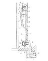
図1は本発明に係る第一の床下配管構造の実施形態を示す全体図、図2は同床下配管構造に用いる排水ヘッダーの斜視図、図3は同排水ヘッダーの断面図、図4は同排水ヘッダーの分解断面図、図5は同床下配管構造に用いるバイパス通気管の側面図、図6は同床下配管構造に用いる渦流発生器の断面図、図7は同渦流発生器の蓋を外した平面図、図8は同床下配管構造の拡大部分断面図である。 1 is an overall view showing an embodiment of a first underfloor piping structure according to the present invention, FIG. 2 is a perspective view of a drainage header used in the underfloor piping structure, FIG. 3 is a sectional view of the drainage header, and FIG. FIG. 5 is a side view of a bypass ventilation pipe used for the underfloor piping structure, FIG. 6 is a sectional view of a vortex generator used for the underfloor piping structure, and FIG. FIG. 8 is an enlarged partial sectional view of the underfloor piping structure.
図1に示す床下配管構造では、床下の土間コンクリート1の上に、合成樹脂製の排水ヘッダー2が設置されており、この排水ヘッダー2の上流側端部の接続口2aと下流側端部の接続口2bと側部の接続口2cには、上流側排水管3aと下流側排水管3bと水設備からの排水枝管(不図示)がそれぞれ接続されている。そして、バイパス通気管4の両端が、直角エルボ継手4a,4aを介して排水ヘッダー2の上部開口2dと下流側排水管3bの途中のチーズ継手3cに接続されており、図8に示すように、このバイパス通気管4によって排水ヘッダー2の内部上方空間V1と下流側排水管3bの内部上方空間V2が連通されている。
In the underfloor piping structure shown in FIG. 1, a
また、布基礎5の内側の土間コンクリート1の箱抜き部分1aには、合成樹脂製の渦流発生器6が設置されており、その側部の接続口6aには下流側排水管3bが接続されている。そして、この渦流発生器6の底部の接続口6bには、布基礎5を貫通する基礎貫通排水管3dの上流側端が大曲り継手3eと深さ調節用の縦管3fを介して下方から接続されており、この基礎貫通排水管3dの下流側端は、屋外の排水管路(不図示)の始端又は途中に埋設された渦流を発生させる排水桝7の側部の接続口7aに接続されている。
Further, a
上記の排水ヘッダー2は、図2に示すように、排水の流れが良好な卵形の断面形状を有する横筒体であって、その上流側端部には上流側排水管3aを接続する接続口2aが設けられ、下流側端部には下流側排水管3bを接続する接続口2bが設けられ、両側部には排水枝管(不図示)を接続する複数の接続口2c,2cが設けられている。
As shown in FIG. 2, the
上流側端部の接続口2aと両側部の接続口2cはいずれも、その上端が排水ヘッダー2の上端と略同一の高さとなるように上方に偏位して設けられており、排水ヘッダー2の内部の水位が上昇しても、これらの接続口2a,2cに接続される上流側排水管3aや排水枝管が閉塞されないようになっている。一方、下流側端部の接続口2bは、これに接続される下流側排水管3bの内底面の最下部と排水ヘッダー2の内底面の最下部とが同じ高さとなるように、下方に偏位して設けられており、排水が排水ヘッダー2の底部に滞溜することなく全て下流側排水管3bに流出するようになっている。
Both the upstream
また、この排水ヘッダー2の上部には複数の開口2dが設けられており、そのうち最も下流側に位置する上部開口2dは、バイパス通気管4の接続口として利用されるものである。その他の上部開口2dは点検口として利用されるものであり、キャップ2eが脱着自在に取付けられている。
In addition, a plurality of
この排水ヘッダー2は合成樹脂で一体成形されたものではなく、図3,図4に示すように、合成樹脂で成形された複数のヘッダー用継手2f,2fと上流側端部閉塞部材2gと下流側端部閉塞部材2hを接合一体化したものである。
This
ヘッダー用継手2fは、卵形の断面形状を有する短尺筒体の一端側(上流端側)に受口2iを形成し、短尺筒体のいずれか片側面に排水枝管の接続口2cを上方に偏位させて形成すると共に、短尺筒体の上面に開口2dを形成したものであって、点検口として利用される上部開口2dにはキャップ2eが脱着自在に螺合されている。
The
また、上流側端部閉塞部材2gは、卵形の形状を備えた閉塞板の片側に、ヘッダー用継手2fの受口2iに差し込まれる差込み筒部2jを形成すると共に、上流側排水管3aの接続口2aを閉塞板の上方に偏位させて形成したものであり、下流側端部閉塞部材2hは、下流側の開口端が下方に偏心した先窄まり形状の漏斗型筒体の上流側の開口端に、ヘッダー用継手2fが差し込まれる受口2kを形成すると共に、下方に偏心した下流側の開口端に、下流側排水管3bの接続口2bを形成したものである。
Further, the upstream
この排水ヘッダー2は、上記のヘッダー用継手2fの受口2iに、隣接する上流側のヘッダー用継手2fの他端側(下流側)の端部を差し込んで接着剤で水密的に接続し、この上流側のヘッダー用継手2fの受口2iに上記の上流側端部閉塞部材2gの差込み筒部2jを差し込んで接着剤で水密的に接続すると共に、下流側のヘッダー用継手2fの端部を下流側端部閉塞部材2hの受口2kに差し込んで接着剤で水密的に接続することにより組み立てられたものである。従って、ヘッダー用継手2fの接続個数を増減することによって、排水枝管の接続口2cを所望数備えた排水ヘッダー2を組み立てることができ、また、片側面に接続口2cが形成されたヘッダー用継手2fと、反対側面に接続口2cが形成されたヘッダー用継手2fとの組合わせ方によって、片側面のみに接続口2cを有する排水ヘッダー2や、両側面に所望数の接続口2cを有する排水ヘッダー2を組み立てることができる。
The
上記の排水ヘッダー2は、図1、図8に示すように、その両端部をヘッダー支持具8,8で支持することにより、所定の流れ勾配を付けて土間コンクリート1の上に設置されている。
As shown in FIGS. 1 and 8, the
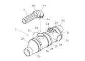
バイパス通気管4は、図5に示すように、コルゲート管などの可撓性を備えた合成樹脂管からなるものであって、その両端には直角エルボ継手4a,4aが取付けられており、抜止めリング4b,4bによって通気管4の両端が直角エルボ継手4a,4aから抜け出さないように係止されている。そして、直角エルボ継手4aの差込み口4cの外周面には,リング状の防水パッキンを嵌着するためのパッキン嵌着溝4dが複数条形成されている。
As shown in FIG. 5, the
このバイパス通気管4は、両端の直角エルボ継手4a,4aのパッキン嵌着溝4d,4dに防水パッキンを嵌着して、図8に示すように、上流側端の直角エルボ継手4aの差込み口4cを排水ヘッダー2の上部開口2d(下流側に位置する方の上部開口2d)に水密的に差込み接続すると共に、下流側端の直角エルボ継手4aの差込み口4cを下流側排水管3bの途中のチーズ継手3cの上部接続口3gに水密的に差込み接続することによって、排水ヘッダー2の内部上方空間V1と下流側排水管3bの内部上方空間V2を連通し、下流側排水管3bの排水ヘッダー近傍部分が排水Wで閉塞されても、排水ヘッダー2内部に負圧が発生するのを防止するものである。従って、排水Wで閉塞される下流側排水管3bの排水ヘッダー近傍部分よりも下流側の内部上方空間V2を確保できる箇所にチーズ継手3cを取付け、該チーズ継手3cの上部接続口3gにバイパス通気管4の下流側端の直角エルボ継手4aの差込み口4cを差込み接続することが大切である。実験を繰り返した結果、下流側排水管3bが例えばVU管の呼径75mm(以下VU75と記す)の排水管であれば、下流側排水管3bの上流側端から略50cmまでの部分は内部上方空間V2が確保され難く、上流側端から略70cm以上離れた部分は内部上方空間V2が確保されることが分かったので、具体的にVU75の下流側排水管3bを用いる場合は、下流側排水管3bの上流側端から少なくとも略70cm離れた部分にチーズ継手3cを取付けてバイパス通気管4の下流側端の直角エルボ継手4aを接続することが好ましい。
The
布基礎5の内側近傍に設置された渦流発生器6は、図6、図7に示すように、その開口上部6cが円環状に形成されており、この円環状の開口上部6cに把手の付いた円形の蓋体6dが脱着可能に嵌着されている。この円環状の開口上部6cの下側の側壁6eは、図7に示すように、途中から曲率半径が徐々に減少して底壁6fの接続口6bに至る渦巻き状に形成されており、この渦巻き状の側壁6eの始端部と終端部が平らな縦壁6gで連結されている。そして、下流側排水管3bを接続する接続口6aは、渦流発生器6の片側に偏位して側壁6eの始端側の下部から上記の縦壁6gと並行に突設されており、底壁6fの接続口6bは、平面視したとき渦巻き状の側壁6eの終端部に内接する位置に形成されている。従って、接続口6aに接続された下流側排水管3bから渦流発生器6に流入した排水は、渦巻き状の側壁6eに沿って渦流を生じ、空気芯を形成しながら渦流に大きな乱れを生じることなく渦流の勢いを保って、底壁6fの接続口6bから深さ調節用の縦管3f、大曲り継手3eを流落して基礎貫通排水管3dへ流れるようになっている。また、この渦流発生器6のように、下流側排水管3bを接続する接続口6aが側壁6eの始端側の下部から突設されていると、流入側の接続口6aと底壁6fの流出側の接続口3bとの高低差が僅かであるため、下流側排水管3bの高さを低くおさえることにより、床下配管の延長距離を延ばすことができる。
As shown in FIGS. 6 and 7, the
また、既述したように基礎貫通排水管3dが大曲り継手3eと深さ調節用の縦管3fを介して渦流発生器6の底壁の接続口6bに接続されていると、切断により深さ調節用の縦管3fの長さを変えるだけで簡単に基礎貫通排水管3dの深さ位置を調節できると共に、この縦管3f及び接続口6bを中心に渦流発生器6を回転させて、下流側排水管3bを布基礎5に対して所望の角度となるように配管できるので、施工性及び配管の自由度が向上する。
Further, as described above, if the basic through
基礎貫通排水管3dの下流側端部を接続する排水桝7は、屋外の排水管路(不図示)の始端又は途中に埋設されたもので、渦流を発生させる排水桝である。即ち、この排水桝7は、基礎貫通排水管3dを接続する側壁上部の接続口7aが桝の中心より片側に偏位して形成されており、基礎貫通排水管3dから流入した排水が排水桝7の側壁内面沿いに流れて渦流となり、下部の接続口7bから屋外の排水管路(不図示)へ排水されるようになっている。
A
以上のような床下配管構造では、洗面台、台所、浴室、トイレなどの各水設備からの排水が上流側排水管3aや排水枝管(不図示)を通って排水ヘッダー2に多量に流入し、図8に示すように、排水ヘッダー2内部の排水Wの水位が下流側端部の接続口2bより高くなると、下流側排水管3bの排水ヘッダー近傍部分が排水Wで閉塞されるが、このように閉塞されても、下流側排水管3bの閉塞箇所より下流側の内部上方空間V2と排水ヘッダー2の内部上方空間V1がバイパス通気管4によって連通しているため、よほど大量の排水によって通気管4の通気作用が損なわれない限り、排水ヘッダー2や上流側排水管3aや排水枝管は下流側排水管3bと同じ大気圧に保たれ、負圧を生じることはない。そして、下流側排水管3bから渦流発生器6に流入した排水は渦流となり、その中心に空気芯が形成されて渦流発生器6の底部の接続口6bから高さ調節用の縦管3f、大曲り継手3eを通って基礎貫通排水管3dに流れ落ちるため、これらの縦管3f、大曲り継手3e、基礎貫通排水管3dも排水Wで閉塞されることがなく、更に、基礎貫通排水管3dから屋外の排水桝7に流入した排水も渦流となって屋外の排水管路へ排水されるため、屋外の排水管路が排水で閉塞されることもない。従って、下流側排水管3bは常に通気が確保されて大気圧に保たれるので、この下流側排水管3bとバイパス通気管4で連通している排水ヘッダー2や、この排水ヘッダー2に接続された上流側排水管3a、排水枝管等も大気圧に保たれ、上記のように下流側排水管3bの排水ヘッダー近傍箇所が排水Wで閉塞されても、バイパス通気管4の通気作用が損なわれるほどの大量の排水が流れない限り、上流側排水管3aや排水枝管に負圧が発生して水設備のトラップの封水破壊を生じる心配はない。
In the underfloor piping structure as described above, a large amount of drainage from each water facility such as a wash basin, kitchen, bathroom, and toilet flows into the
図9は本発明に係る第二の床下配管構造の実施形態を示す全体図、図10は同床下配管構造に用いる渦流発生器を連設した第二の排水ヘッダーを示す斜視図である。 FIG. 9 is an overall view showing an embodiment of a second underfloor piping structure according to the present invention, and FIG. 10 is a perspective view showing a second drainage header in which eddy current generators used in the underfloor piping structure are connected.
この床下配管構造は、前述の渦流発生器6に代えて、渦流発生器が連設された第二の排水ヘッダー20を家屋の布基礎5の内側に設置し、この排水ヘッダー20の上流側端部の接続口2aに下流側排水管3bを接続している点で、前述の床下配管構造と異なっている。
In this underfloor piping structure, instead of the
第二の排水ヘッダー20は、図10に示すように、その下流側端部に渦流発生器60を連設したものであって、排水ヘッダー20それ自体は、前述の下流側端部閉塞部材2hを取り外した排水ヘッダー2と同じものであるから、図9、図10において同一部材に同一符号を付して、排水ヘッダー20それ自体の説明を省略し、渦流発生器60についてのみ説明することにする。
As shown in FIG. 10, the
この渦流発生器60は、図10に示すように、その排水導入通路部60aの端部に受口60bを備え、この受口60bに排水ヘッダー20の下流側端部を嵌合して接着剤で水密的に接合することにより、排水ヘッダー20の下流側端部に水漏れなく連設されている。そして、排水導入通路部60aは、受口60bから前方に向かって先細り状に絞った形状の通路部に形成されている。
As shown in FIG. 10, the
この渦流発生器60は、その排水導入通路部60aから延びる一方の側壁が、曲率半径の漸減する渦巻き状の湾曲側壁部60cに形成されており、この湾曲側壁部60cは排水ヘッダー20の片側に膨出して、その曲率半径の小さい方の端部60d(終端部)が排水導入通路部60aの他方の側壁に連なっている。そして、この渦流発生器60の底壁に形成された接続口60eには、基礎貫通排水管3dが大曲り継手3eと深さ調節用の縦管3fを介して接続されており、この底壁の接続口60eは、渦流発生器60を平面視したとき、湾曲側壁部60cの曲率半径の小さい方の端部2dに内接する位置関係となっている。また、この渦流発生器60の排水導入通路部60aを除いた上端開口部60fには、蓋体60gが脱着可能に被着されている。
In the
このような渦流発生器60が排水ヘッダー20の下流側端部に連設されていると、排水ヘッダー20から排水導入通路部60aを通って渦流発生器60へ流入した排水が、湾曲側壁部60cの内面に沿って流れながら渦流となり、湾曲側壁部60cの曲率半径の小さい方の端部2dから、渦流に大きな乱れを生じることなく渦流の勢いを保ったまま、底壁の接続口60eに流れ込んで基礎貫通排水管3dへ流れるため、渦流の中心に空気芯が確実に形成されて、基礎貫通排水管3dの閉塞が防止されることになる。特に、この実施形態のように渦巻き状の湾曲側壁部60cが排水ヘッダー20の片側に膨出していると、渦流を発生させる湾曲側壁部60cの沿面距離が長くなって、乱れの少ない勢いのある渦流を発生させる利点がある。
When such a
図9に示す床下配管構造の他の構成は、前述した図1の床下配管構造と同様であるから、図9において同一部材に同一符号を付して説明を省略する。 Since the other configuration of the underfloor piping structure shown in FIG. 9 is the same as that of the underfloor piping structure of FIG. 1 described above, the same members in FIG.
このような床下配管構造も、バイパス通気管4によって排水ヘッダー2の内部上方空間と下流側排水管3bの内部上方空間が連通され、また、下流側排水管3bから第二の排水ヘッダー20を通ってその下流側端部の渦流発生器60に流入した排水は渦流となり、空気芯を形成しながら流落して基礎貫通排水管3dを閉塞することがなく、更に、屋外の排水桝7でも渦流が発生して屋外の排水管路を閉塞することがない。従って、下流側排水管3bの排水ヘッダー2近傍部分が排水で閉塞されても、排水ヘッダー2、該ヘッダーに接続されている上流側排水管3a及び排水枝管、下流側排水管3b、第二の排水ヘッダー20、該ヘッダーに接続されている排水枝管、深さ調節用の縦管3f、大曲り継手3e、基礎貫通排水管3dなどの全ての通気が確保されて大気圧に保たれるため、バイパス通気管4の通気作用が損なわれるほどの大量の排水が流れない限り、負圧による水設備のトラップの封水破壊を生じることはない。しかも、この床下配管構造は、第二の排水ヘッダー20を増設しているため、より多くの排水枝管を接続して一括排水の効率を高めることができる。
In such an underfloor piping structure, the internal space above the
2 排水ヘッダー
2a 上流側端部の接続口
2b 下流側端部の接続口
2c 側部の接続口
2d 上部開口
3a 上流側排水管
3b 下流側排水管
3c チーズ継手
3d 基礎貫通排水管
4 バイパス通気管
4a 直角エルボ継手
5 建物の基礎(布基礎)
6 渦流発生器
6a 側部の接続口
6b 底部の接続口
7 渦流を発生させる排水桝
20 第二の排水ヘッダー
60 渦流発生器
V1 排水ヘッダーの内部上方空間
V2 下流側排水管の内部上方空間
2
6 Eddy
Claims (3)
Priority Applications (1)
| Application Number | Priority Date | Filing Date | Title |
|---|---|---|---|
| JP2005131379A JP4673127B2 (en) | 2005-04-28 | 2005-04-28 | Underfloor piping structure |
Applications Claiming Priority (1)
| Application Number | Priority Date | Filing Date | Title |
|---|---|---|---|
| JP2005131379A JP4673127B2 (en) | 2005-04-28 | 2005-04-28 | Underfloor piping structure |
Publications (2)
| Publication Number | Publication Date |
|---|---|
| JP2006307536A true JP2006307536A (en) | 2006-11-09 |
| JP4673127B2 JP4673127B2 (en) | 2011-04-20 |
Family
ID=37474728
Family Applications (1)
| Application Number | Title | Priority Date | Filing Date |
|---|---|---|---|
| JP2005131379A Active JP4673127B2 (en) | 2005-04-28 | 2005-04-28 | Underfloor piping structure |
Country Status (1)
| Country | Link |
|---|---|
| JP (1) | JP4673127B2 (en) |
Cited By (2)
| Publication number | Priority date | Publication date | Assignee | Title |
|---|---|---|---|---|
| JP2011183673A (en) * | 2010-03-09 | 2011-09-22 | Japan Steel Works Ltd:The | Method and device for discharging pellet cooling/carrying water |
| CN105673977A (en) * | 2016-04-05 | 2016-06-15 | 成都川路塑胶集团有限公司 | Multi-channel same-floor drainage water collector |
Citations (3)
| Publication number | Priority date | Publication date | Assignee | Title |
|---|---|---|---|---|
| JPH05156675A (en) * | 1991-12-06 | 1993-06-22 | Taisei Corp | Drum-shaped indoor drainage system |
| JP2002061247A (en) * | 2000-08-11 | 2002-02-28 | Sekisui Chem Co Ltd | Drainage system for residence |
| JP2003129541A (en) * | 2001-10-26 | 2003-05-08 | Sekisui Chem Co Ltd | Drainage piping system |
-
2005
- 2005-04-28 JP JP2005131379A patent/JP4673127B2/en active Active
Patent Citations (3)
| Publication number | Priority date | Publication date | Assignee | Title |
|---|---|---|---|---|
| JPH05156675A (en) * | 1991-12-06 | 1993-06-22 | Taisei Corp | Drum-shaped indoor drainage system |
| JP2002061247A (en) * | 2000-08-11 | 2002-02-28 | Sekisui Chem Co Ltd | Drainage system for residence |
| JP2003129541A (en) * | 2001-10-26 | 2003-05-08 | Sekisui Chem Co Ltd | Drainage piping system |
Cited By (2)
| Publication number | Priority date | Publication date | Assignee | Title |
|---|---|---|---|---|
| JP2011183673A (en) * | 2010-03-09 | 2011-09-22 | Japan Steel Works Ltd:The | Method and device for discharging pellet cooling/carrying water |
| CN105673977A (en) * | 2016-04-05 | 2016-06-15 | 成都川路塑胶集团有限公司 | Multi-channel same-floor drainage water collector |
Also Published As
| Publication number | Publication date |
|---|---|
| JP4673127B2 (en) | 2011-04-20 |
Similar Documents
| Publication | Publication Date | Title |
|---|---|---|
| JP4832079B2 (en) | Small swirl flow generating joint | |
| JP6654823B2 (en) | Sewage basin and temporary toilet system | |
| JP5483924B2 (en) | Drainage pipe joint and drainage structure using this drainage pipe joint | |
| JP4673127B2 (en) | Underfloor piping structure | |
| JP6377895B2 (en) | Piping unit and piping construction method | |
| JP6194505B2 (en) | Self-sealing valve member and joint member | |
| JP4673124B2 (en) | Drainage header | |
| JP4454412B2 (en) | Underfloor piping ventilation structure | |
| JP6339410B2 (en) | Swivel joint and drainage system using the same | |
| JP2005194727A (en) | Drain adapter | |
| JP2007308961A (en) | Horizontal piping joint and drain pipeline structure using it | |
| JP2008133721A (en) | Swirling flow type pipe coupling | |
| JP2019141547A (en) | Temporary toilet | |
| JP2008144355A (en) | Underfloor drain piping system | |
| JP2007113343A (en) | Collective drainage device and header | |
| JP2007063813A (en) | Junction pipe joint | |
| JP5473013B2 (en) | Basic through-pipe structure | |
| JP5324853B2 (en) | Siphon drainage system | |
| JP4776359B2 (en) | Basic through-piping structure and swirl type drainage basin used therefor | |
| JP6019287B2 (en) | Drain trap | |
| JP5369397B2 (en) | Drain socket | |
| JP2018053640A (en) | Drain pipe member | |
| JP2004278099A (en) | Drainage structure of drain pipeline, and drainage joint | |
| JP6279274B2 (en) | Piping unit and piping construction method | |
| JP2005147225A (en) | Drainage system for residence |
Legal Events
| Date | Code | Title | Description |
|---|---|---|---|
| A621 | Written request for application examination |
Free format text: JAPANESE INTERMEDIATE CODE: A621 Effective date: 20080416 |
|
| A977 | Report on retrieval |
Free format text: JAPANESE INTERMEDIATE CODE: A971007 Effective date: 20101008 |
|
| A131 | Notification of reasons for refusal |
Free format text: JAPANESE INTERMEDIATE CODE: A131 Effective date: 20101013 |
|
| A521 | Request for written amendment filed |
Free format text: JAPANESE INTERMEDIATE CODE: A523 Effective date: 20101126 |
|
| TRDD | Decision of grant or rejection written | ||
| A01 | Written decision to grant a patent or to grant a registration (utility model) |
Free format text: JAPANESE INTERMEDIATE CODE: A01 Effective date: 20110105 |
|
| A01 | Written decision to grant a patent or to grant a registration (utility model) |
Free format text: JAPANESE INTERMEDIATE CODE: A01 |
|
| A61 | First payment of annual fees (during grant procedure) |
Free format text: JAPANESE INTERMEDIATE CODE: A61 Effective date: 20110120 |
|
| R150 | Certificate of patent or registration of utility model |
Free format text: JAPANESE INTERMEDIATE CODE: R150 Ref document number: 4673127 Country of ref document: JP Free format text: JAPANESE INTERMEDIATE CODE: R150 |
|
| FPAY | Renewal fee payment (event date is renewal date of database) |
Free format text: PAYMENT UNTIL: 20140128 Year of fee payment: 3 |
|
| S531 | Written request for registration of change of domicile |
Free format text: JAPANESE INTERMEDIATE CODE: R313531 |
|
| FPAY | Renewal fee payment (event date is renewal date of database) |
Free format text: PAYMENT UNTIL: 20140128 Year of fee payment: 3 |
|
| R350 | Written notification of registration of transfer |
Free format text: JAPANESE INTERMEDIATE CODE: R350 |
|
| FPAY | Renewal fee payment (event date is renewal date of database) |
Free format text: PAYMENT UNTIL: 20140128 Year of fee payment: 3 |
|
| R250 | Receipt of annual fees |
Free format text: JAPANESE INTERMEDIATE CODE: R250 |
|
| R250 | Receipt of annual fees |
Free format text: JAPANESE INTERMEDIATE CODE: R250 |
|
| R250 | Receipt of annual fees |
Free format text: JAPANESE INTERMEDIATE CODE: R250 |
|
| R250 | Receipt of annual fees |
Free format text: JAPANESE INTERMEDIATE CODE: R250 |
|
| R250 | Receipt of annual fees |
Free format text: JAPANESE INTERMEDIATE CODE: R250 |
|
| R250 | Receipt of annual fees |
Free format text: JAPANESE INTERMEDIATE CODE: R250 |
|
| S533 | Written request for registration of change of name |
Free format text: JAPANESE INTERMEDIATE CODE: R313533 |
|
| R350 | Written notification of registration of transfer |
Free format text: JAPANESE INTERMEDIATE CODE: R350 |
|
| R250 | Receipt of annual fees |
Free format text: JAPANESE INTERMEDIATE CODE: R250 |
|
| R250 | Receipt of annual fees |
Free format text: JAPANESE INTERMEDIATE CODE: R250 |
|
| R250 | Receipt of annual fees |
Free format text: JAPANESE INTERMEDIATE CODE: R250 |
|
| R250 | Receipt of annual fees |
Free format text: JAPANESE INTERMEDIATE CODE: R250 |
|
| R250 | Receipt of annual fees |
Free format text: JAPANESE INTERMEDIATE CODE: R250 |