JP2006301154A - Zoom lens and electronic imaging apparatus using the same - Google Patents
Zoom lens and electronic imaging apparatus using the same Download PDFInfo
- Publication number
- JP2006301154A JP2006301154A JP2005120742A JP2005120742A JP2006301154A JP 2006301154 A JP2006301154 A JP 2006301154A JP 2005120742 A JP2005120742 A JP 2005120742A JP 2005120742 A JP2005120742 A JP 2005120742A JP 2006301154 A JP2006301154 A JP 2006301154A
- Authority
- JP
- Japan
- Prior art keywords
- lens
- lens group
- zoom
- zoom lens
- object side
- Prior art date
- Legal status (The legal status is an assumption and is not a legal conclusion. Google has not performed a legal analysis and makes no representation as to the accuracy of the status listed.)
- Pending
Links
Images


Landscapes
- Lenses (AREA)
Abstract
Description
本発明は、ズームレンズとそれを用いた電子撮像装置に関し、特に、画角の広い領域を含むズームレンズと電子撮像装置に関するものである。 The present invention relates to a zoom lens and an electronic imaging device using the same, and more particularly to a zoom lens and an electronic imaging device including a wide field angle region.
所謂レンズ一体型デジタルカメラ等に適用可能な高い結像性能を有し、画角の広い領域を含むズームレンズへの要望が高まっている。また、これらのズームレンズは単に撮影範囲が広いだけでなく、所謂デジタルズームと呼ばれる撮影画像の一部を拡大する機能との組み合わせで、撮影範囲を変更できる自由度を広げることが期待されている。ただし、デジタルズームの場合、撮影画像の一部を拡大するので、撮影レンズ性能や撮像素子性能より画質が劣化するので、ある程度変倍比を持つズームレンズが望まれている。 There is a growing demand for a zoom lens that has high imaging performance applicable to a so-called lens-integrated digital camera and that includes a wide field angle region. Further, these zoom lenses are expected not only to have a wide shooting range, but also to expand the flexibility of changing the shooting range in combination with a so-called digital zoom function for enlarging a part of a shot image. However, in the case of digital zoom, since a part of the photographed image is enlarged, the image quality is deteriorated more than the photographing lens performance and the imaging device performance. Therefore, a zoom lens having a certain zoom ratio is desired.
これまで、コンパクトでズーム倍率が3倍を越え、画角の広い領域を含むズームレンズ等は提案されていなかった。 So far, a zoom lens or the like that is compact, has a zoom magnification exceeding 3 times, and includes a wide angle of view has not been proposed.
これまでの提案としては、ズーム倍率が3倍を越え、比較的画角が広くコンパクトな撮影用ズームレンズとして、特許文献1や特許文献2等のものがあるが、さらなる広角化が望まれている。
本発明は従来技術のこのような状況に鑑みてなされたものであり、その目的は、十分な広角域を有し、高変倍のズームレンズやそれを用いた撮像装置を提供することである。 The present invention has been made in view of such a situation of the prior art, and an object thereof is to provide a zoom lens having a sufficiently wide angle range and a high zoom ratio and an imaging device using the same. .
さらには、コンパクトな構成をとり得る構成としながらも、変倍比が3倍以上のズームレンズであって、電子撮像素子を用いる撮影用のズームレンズ、電子撮像装置を提供することを目的としている。 Furthermore, an object of the present invention is to provide a zoom lens and an electronic imaging device for taking a picture using an electronic imaging device, which is a zoom lens having a zoom ratio of 3 times or more while having a compact configuration. .
上記目的を達成する本発明の第1のズームレンズは、物体側より順に、負屈折力の第1レンズ群、正屈折力の第2レンズ群、正屈折力の第3レンズ群を有し、変倍時各レンズ群の間隔を変化させ、以下の条件式(1)乃至(4)を満足することを特徴とするものである。 The first zoom lens of the present invention that achieves the above object has, in order from the object side, a first lens group having a negative refractive power, a second lens group having a positive refractive power, and a third lens group having a positive refractive power, The zoom lens system is characterized in that the following conditional expressions (1) to (4) are satisfied by changing the interval between the lens units during zooming.
0.80<IH/fw <1.5 ・・・(1)
2.7<ft /fw <12 ・・・(2)
0.05<|da /f1G|<10 ・・・(3)
0<db /f2G<3 ・・・(4)
ただし、IHはズームレンズの撮影像高、
fw はズームレンズ全系の広角端での焦点距離、
ft はズームレンズ全系の望遠端での焦点距離、
f1Gは第1レンズ群の焦点距離、
f2Gは第2レンズ群の焦点距離、
da は、ズームレンズ全系が以下の条件(a)を満足する何れかの焦点距離fraのときの第1レンズ群と第2レンズ群との軸上間隔、
IH/0.92<fra<IH/0.8 ・・・(a)
db は、ズームレンズ全系が以下の条件(b)を満足する何れかの焦点距離frbのときの第1レンズ群と第2レンズ群との軸上間隔、
2.7<frb/fra<5 ・・・(b)
である。
0.80 <IH / f w <1.5 (1)
2.7 < ft / fw <12 (2)
0.05 <| d a / f 1G | <10 (3)
0 <d b / f 2G <3 (4)
Where IH is the image height of the zoom lens,
f w is the focal length at the wide-angle end of the entire zoom lens system,
f t is the focal length at the telephoto end of the entire zoom lens system,
f 1G is the focal length of the first lens group,
f 2G is the focal length of the second lens group,
d a is the axial distance between the first lens group and the second lens group when the entire zoom lens system has any focal length f ra that satisfies the following condition (a):
IH / 0.92 <f ra <IH / 0.8 (a)
d b is the axial distance between the first lens group and the second lens group when the entire zoom lens system has any focal length fr that satisfies the following condition (b):
2.7 <f rb / f ra <5 (b)
It is.
以下に、本発明の第1のズームレンズにおいて上記構成をとる理由と作用を説明する。 Hereinafter, the reason and action of the above configuration in the first zoom lens of the present invention will be described.
物体側より順に、負の第1レンズ群、可変間隔を挟んで第1レンズ群よりも像側に配された正の第2レンズ群とを含む構成とすることで、大きい画角で入射する光束に対して負の屈折力にて光束を屈折させ、正屈折力の第2レンズ群に導く構成となる。 In order from the object side, a negative first lens group and a positive second lens group disposed on the image side of the first lens group with a variable interval in between are incident at a large angle of view. The light beam is refracted with a negative refracting power and guided to the second lens group having a positive refracting power.
そのため、条件式(1)を満足することにより、広角端での焦点距離による広い撮影画角を維持しつつも、第1レンズ群の外径を小さくすることが可能となる。第1レンズ群の外径を小さくすることにより、第1レンズ群の構成長コンパクト化や第1レンズ群のパワーを強くするのに有利となる。 Therefore, by satisfying conditional expression (1), it is possible to reduce the outer diameter of the first lens group while maintaining a wide shooting angle of view due to the focal length at the wide-angle end. By reducing the outer diameter of the first lens group, it is advantageous to make the configuration length of the first lens group compact and to increase the power of the first lens group.
そして、本発明では、さらに正の第2レンズ群の像面側に正の第3レンズ群を配置することにより、条件式(2)で規定する変倍比を満足しながら、光束の像面への入射角度の変化を低減させることができる。 In the present invention, the positive third lens group is further arranged on the image plane side of the positive second lens group, so that the image plane of the luminous flux is satisfied while satisfying the zoom ratio defined by the conditional expression (2). It is possible to reduce the change in the incident angle to the.
特に、ズームレンズの像側に光学像を電気信号に変換する電子撮像素子を配する構成とした場合、本発明のズームレンズでは、テレセントリック性の確保ができるため、光線が撮像素子へ斜めに入射することによる悪影響を低減できる。 In particular, when an electronic image sensor that converts an optical image into an electrical signal is arranged on the image side of the zoom lens, the zoom lens of the present invention can ensure telecentricity, so that light is incident on the image sensor at an angle. It is possible to reduce the adverse effects caused by doing.
条件式(1)の下限の0.80を越えると、撮影範囲が狭くなり、画像処理等でも撮影範囲がカバーできなくなる。一方、条件式(1)の上限の1.5を越えると、光学系全体の屈折力が強くなりすぎ、条件式(2)を満足する変倍比を確保しようとすると、変倍に伴う各群での収差補正が難しくなる。 If the lower limit of 0.80 of conditional expression (1) is exceeded, the shooting range becomes narrow, and the shooting range cannot be covered even by image processing or the like. On the other hand, if the upper limit of 1.5 of the conditional expression (1) is exceeded, the refractive power of the entire optical system becomes too strong, and if an attempt is made to secure a zoom ratio that satisfies the conditional expression (2), It becomes difficult to correct aberrations in groups.
条件式(2)の上限の12を越えると、負の第1レンズ群への屈折力分担の負荷が大きくなり、収差変動の補正を行いながらのコンパクト性の確保が難しくなる。条件式(2)の下限の2.7を越えると、コンパクト性の向上程度に対して、遠景の被写体を大きく撮影するときの画質の劣化度が大きくなり好ましくない。 If the upper limit of 12 in conditional expression (2) is exceeded, the burden of refracting power sharing on the negative first lens group will increase, making it difficult to ensure compactness while correcting aberration fluctuations. Exceeding the lower limit of 2.7 of the conditional expression (2) is not preferable because the degree of deterioration in image quality when shooting a distant subject is greatly increased with respect to the improvement in compactness.
また、条件式(2)の上限を越えると、第2レンズ群の移動量が大きくなりやすく、コンパクト性を損なう。 If the upper limit of conditional expression (2) is exceeded, the amount of movement of the second lens group tends to be large, and the compactness is impaired.
条件式(3)は、第1レンズ群におけるパワーを、式(a)で規定する任意の焦点距離fraにおける第1、2レンズ群間隔にて規定したものである。 Conditional expression (3) defines the power in the first lens group at the interval between the first and second lens groups at an arbitrary focal length fra defined by expression (a).
条件式(3)の下限の0.05を越えると、第1レンズ群のパワーが弱くなりすぎ、望遠端使用時の全長が長くなる。一方、条件式(3)の上限の10を越えると、第1レンズ群と第2レンズ群の間隔が広くなりすぎコンパクト化に反する。 If the lower limit of 0.05 of conditional expression (3) is exceeded, the power of the first lens group becomes too weak and the total length when the telephoto end is used becomes long. On the other hand, if the upper limit of 10 in the conditional expression (3) is exceeded, the distance between the first lens group and the second lens group becomes too large, which is contrary to compactness.
条件式(4)は、第2レンズ群におけるパワーを、式(b)で規定する変倍比を確保した任意の焦点距離frbにおける第1、2レンズ群間隔にて規定したものである。 Conditional expression (4) defines the power in the second lens group at the interval between the first and second lens groups at an arbitrary focal length frb in which the zoom ratio defined in expression (b) is ensured.
条件式(4)の下限の0を越えると、第1レンズ群と第2レンズ群が干渉する。条件式(4)の上限の3を越えると、第2レンズ群のパワーが強くなる等、第2レンズ群以降の構成が複雑になる。 If the lower limit of 0 in the conditional expression (4) is exceeded, the first lens group and the second lens group interfere with each other. Exceeding the upper limit of 3 to conditional expression (4) complicates the configuration after the second lens group, such as an increase in the power of the second lens group.
なお、条件式(1)について撮影範囲をより広くして、下限値を0.85、さらには0.87とするとより好ましい。 For conditional expression (1), it is more preferable that the photographing range is made wider and the lower limit value is 0.85, further 0.87.
各群での収差をより低減しやすくするため、上限値を1.3、さらには1.1とするとより好ましい。 In order to make it easier to reduce the aberration in each group, it is more preferable that the upper limit value is 1.3, and further 1.1.
条件式(2)について、遠景撮影時の画質をより良好にするため、下限値を3.5、さらには4.0とするとより好ましい。 Regarding conditional expression (2), in order to improve the image quality at the time of distant view shooting, it is more preferable to set the lower limit value to 3.5, and further to 4.0.
よりコンパクトにしやすくするため、上限値を7.0、さらには6.0とするとより好ましい。 In order to make it more compact, it is more preferable that the upper limit value is 7.0, and even 6.0.
条件式(3)について、全長短縮のため、下限値を1.0、さらには2.0とするとより好ましい。 For conditional expression (3), it is more preferable to set the lower limit to 1.0, and further to 2.0 in order to reduce the overall length.
上限値を7.0、さらには5.0とするとより好ましい。 More preferably, the upper limit value is 7.0, more preferably 5.0.
条件式(4)について、上限値を1.0、さらには0.2とすると、第2レンズ群以降の構成がより簡略化できるので、より好ましい。 Regarding conditional expression (4), if the upper limit value is 1.0, and further 0.2, it is more preferable because the configuration after the second lens group can be further simplified.
また、第1レンズ群での外径の大型化を抑えつつ、ズームレンズ全系での光線の射出角を小さくし、系全体の収差補正を行いやすくするために、第1レンズ群よりも像面側で第2レンズ群の最も像側のレンズよりも物体側に、明るさ絞り(開口絞り)を配することが好ましい。 In addition, in order to reduce the light emission angle of the entire zoom lens system and to facilitate aberration correction of the entire system while suppressing the increase in the outer diameter of the first lens group, it is easier to correct the aberration than the first lens group. It is preferable to provide an aperture stop (aperture stop) closer to the object side than the lens closest to the image side of the second lens group on the surface side.
また、さらには、fra=fw 、frb=ft としてもよい。 In addition, further, f ra = f w, may be as f rb = f t.
その場合、条件式(1)は条件式(a)に、条件式(2)は条件式(b)に置き換わる。 In that case, conditional expression (1) is replaced by conditional expression (a), and conditional expression (2) is replaced by conditional expression (b).
本発明の第2のズームレンズは、第1のズームレンズにおいて、以下の条件式(5)を満足することを特徴とするものである。 The second zoom lens of the present invention is characterized in that, in the first zoom lens, the following conditional expression (5) is satisfied.
−0.07<IH/r1 <0.07 ・・・(5)
ただし、r1 は第1レンズ群中の最も物体側のレンズ面の近軸曲率半径である。
−0.07 <IH / r 1 <0.07 (5)
Here, r 1 is the paraxial radius of curvature of the most object side lens surface in the first lens group.
本発明の第3のズームレンズは、第2のズームレンズにおいて、条件式(5)に代えて以下の条件式(5’)を満足することを特徴とするものである。 The third zoom lens according to the present invention is characterized in that, in the second zoom lens, the following conditional expression (5 ′) is satisfied instead of conditional expression (5).
−0.015<IH/r1 <0.04 ・・・(5’)
以下に、本発明の第2、第3のズームレンズにおいて上記構成をとる理由と作用を説明する。
−0.015 <IH / r 1 <0.04 (5 ′)
Hereinafter, the reason and operation of the second and third zoom lenses according to the present invention will be described.
第1レンズ群中の最も物体側のレンズ面(第1面)の近軸曲率半径を大きくすると、入射瞳位置を浅くすることができるので、レンズ外径の小型化が可能となる。また、軸外での入射光束を構成する各光線と第1面とのなす角の差が小さくなり、コマ収差の補正に有利となる。また、結像性能を維持しつつ撮影範囲を広くすることができる。また、軸上光束径の変化が大きい第1面が光軸付近にて曲率が小さいので、変倍による球面収差の変化を小さくでき、第2レンズ群での収差補正負担を小さくでき、好ましい。 Increasing the paraxial radius of curvature of the lens surface (first surface) closest to the object in the first lens group can make the entrance pupil position shallower, so that the lens outer diameter can be reduced. In addition, the difference in angle formed between each light beam constituting the incident light beam off the axis and the first surface is reduced, which is advantageous for correction of coma aberration. In addition, the imaging range can be widened while maintaining the imaging performance. Further, the first surface having a large change in the axial beam diameter has a small curvature near the optical axis, so that the change in spherical aberration due to zooming can be reduced, and the aberration correction burden on the second lens group can be reduced, which is preferable.
条件式(5)の下限の−0.07を越えると、第1面で軸外光束の入射角が大きくなり、結像性能の維持が難しくなる。上限の0.07を越えると、入射瞳位置が浅くなり、レンズの外径が大きくなりコンパクト性を損なうと共に、画角の確保のため第1レンズ群のレンズ構成を複雑しなければならなくなる。又は、コマ収差の補正に不利となる。そのため、レンズ系全体の構成が複雑になり好ましくない。又は、画角を小さくし、撮影範囲を小さくしなければならなくなる。 If the lower limit of -0.07 in conditional expression (5) is exceeded, the incident angle of the off-axis light beam becomes large on the first surface, and it becomes difficult to maintain the imaging performance. When the upper limit of 0.07 is exceeded, the entrance pupil position becomes shallow, the outer diameter of the lens becomes large and the compactness is impaired, and the lens configuration of the first lens group must be complicated in order to secure the angle of view. Or, it is disadvantageous for correction of coma aberration. Therefore, the configuration of the entire lens system becomes complicated, which is not preferable. Alternatively, the field angle must be reduced and the shooting range must be reduced.
条件式(5)において、下限値を−0.015、さらには0.0とすることがより好ましい。 In conditional expression (5), it is more preferable that the lower limit value be −0.015, more preferably 0.0.
若しくは、上限値を0.04、さらには0.033とすることがより好ましい。 Alternatively, the upper limit value is more preferably 0.04, and further preferably 0.033.
例えば、条件式(5)の上下限の双方を縮減し、条件式(5’)とするとより好ましい。レンズ外径の小型化、結像性能の維持、広い撮影範囲の確保により有利となる。 For example, it is more preferable to reduce both the upper and lower limits of the conditional expression (5) to obtain the conditional expression (5 ′). This is advantageous by reducing the outer diameter of the lens, maintaining the imaging performance, and ensuring a wide imaging range.
さらには、第1レンズ群の最も物体側のレンズ成分が像側に凹面を持つ構成とすると、その凹面の曲率半径が小さくなりすぎることを防止でき、球面収差、コマ収差の補正が良好にできる。 Further, when the lens component closest to the object side in the first lens group has a concave surface on the image side, it is possible to prevent the radius of curvature of the concave surface from becoming too small, and to correct spherical aberration and coma aberration well. .
本発明の第4のズームレンズは、第1〜第3のズームレンズにおいて、広角端から望遠端への変倍時、前記第1レンズ群は移動し、前記第2レンズ群は物体側に移動し、かつ、変倍時に前記第2レンズ群と共に移動する開口絞りを有することを特徴とするものである。 In the fourth zoom lens of the present invention, in the first to third zoom lenses, at the time of zooming from the wide angle end to the telephoto end, the first lens group moves, and the second lens group moves toward the object side. And an aperture stop that moves together with the second lens group upon zooming.
以下に、本発明の第4のズームレンズにおいて上記構成をとる理由と作用を説明する。 Hereinafter, the reason and action of the above-described configuration in the fourth zoom lens of the present invention will be described.
変倍を行う第2レンズ群と共に開口絞りを移動させることで、第2レンズ群への入射光束の範囲の変化を小さくできる。そのため、第2レンズ群の移動に伴う収差変動を抑えることができる。 By moving the aperture stop together with the second lens group that performs zooming, the change in the range of the incident light beam to the second lens group can be reduced. Therefore, it is possible to suppress fluctuations in aberrations associated with the movement of the second lens group.
また、より好ましくは、第1レンズ群を広角端から望遠端への変倍時に像側に移動後、物体側に移動させることで、鏡筒構造を含めコンパクトなズームレンズとし得る。 More preferably, by moving the first lens group to the image side after zooming from the wide-angle end to the telephoto end and then moving to the object side, a compact zoom lens including a lens barrel structure can be obtained.
本発明の第5のズームレンズは、第4のズームレンズにおいて、前記開口絞りは前記第1レンズ群と前記第2レンズ群の間に配置されていることを特徴とするものである。 According to a fifth zoom lens of the present invention, in the fourth zoom lens, the aperture stop is disposed between the first lens group and the second lens group.
以下に、本発明の第5のズームレンズにおいて上記構成をとる理由と作用を説明する。 The reason and action of the fifth zoom lens according to the present invention will be described below.
このような構成により、入射瞳を浅くでき、第1レンズ群の外径を小さくできる。また、第2レンズ群内の製造誤差によるレンズ素子の偏心の影響を小さくしやすくなり、鏡枠構造やレンズ構成を簡易にしやすくできる。 With such a configuration, the entrance pupil can be made shallow, and the outer diameter of the first lens group can be reduced. In addition, the influence of the decentering of the lens element due to the manufacturing error in the second lens group can be easily reduced, and the lens frame structure and the lens configuration can be easily simplified.
本発明の第6のズームレンズは、第1〜第5のズームレンズにおいて、前記ズームレンズが、物体側より順に、屈折力を有するレンズ群を、前記負屈折力の第1レンズ群、前記正屈折力の第2レンズ群、前記正屈折力の第3レンズ群の3群ズームレンズとしたことを特徴とするものである。 According to a sixth zoom lens of the present invention, in the first to fifth zoom lenses, the zoom lens includes, in order from the object side, a lens group having refractive power, the first lens group having negative refractive power, and the positive lens group. The zoom lens is a three-unit zoom lens including a second lens unit having refractive power and a third lens unit having positive refractive power.
以下に、本発明の第6のズームレンズにおいて上記構成をとる理由と作用を説明する。 The reason and action of the sixth zoom lens according to the present invention will be described below.
このような構成により、レンズ系全体として少ない群数で広角レンズ系に有利なレトロフォーカスシステムとし、電子撮像素子に適した射出瞳のコントロールを行うことができる。 With such a configuration, a retrofocus system that is advantageous for a wide-angle lens system with a small number of groups as a whole can be achieved, and exit pupil control suitable for an electronic imaging device can be performed.
また、より好ましくは、第3レンズ群を変倍時に移動させることで、射出瞳のコントロールにより有利となる。 More preferably, moving the third lens group at the time of zooming is more advantageous for controlling the exit pupil.
本発明の第7のズームレンズは、第1〜第6のズームレンズにおいて、前記第1レンズ群の最も物体側のレンズL11は、物体側に凸面を向けた負メニスカスレンズであることを特徴とするものである。 According to a seventh zoom lens of the present invention, in the first to sixth zoom lenses, the most object side lens L11 of the first lens group is a negative meniscus lens having a convex surface facing the object side. To do.
以下に、本発明の第7のズームレンズにおいて上記構成をとる理由と作用を説明する。 Hereinafter, the reason and operation of the seventh zoom lens according to the present invention will be described.
このような構成により、広角端の画角を大きくしつつ、負の歪曲収差の過剰な発生を抑えやすくなる。 With such a configuration, it is easy to suppress excessive generation of negative distortion while increasing the angle of view at the wide-angle end.
本発明の第8のズームレンズは、第1〜第7のズームレンズにおいて、前記第1レンズ群は、物体側より負レンズと軸上の空気間隔を挟んで前記負レンズの像側に配された物体側に凸面を向けた負メニスカスレンズを有することを特徴とするものである。 According to an eighth zoom lens of the present invention, in the first to seventh zoom lenses, the first lens group is disposed on the image side of the negative lens with an air space on the axis between the negative lens and the axis from the object side. And a negative meniscus lens having a convex surface facing the object side.
以下に、本発明の第8のズームレンズにおいて上記構成をとる理由と作用を説明する。 Hereinafter, the reason and action of the above configuration in the eighth zoom lens of the present invention will be described.
このような構成により、軸外光線を徐々に曲げることができるので、軸外収差の発生を抑えられる。 With such a configuration, off-axis rays can be gradually bent, so that occurrence of off-axis aberrations can be suppressed.
本発明の第9のズームレンズは、第1〜第8のズームレンズにおいて、前記第1レンズ群は、非球面を有する負レンズを有することを特徴とするものである。 According to a ninth zoom lens of the present invention, in the first to eighth zoom lenses, the first lens group includes a negative lens having an aspherical surface.
以下に、本発明の第9のズームレンズにおいて上記構成をとる理由と作用を説明する。 The reason and operation of the ninth zoom lens according to the present invention will be described below.
このような構成により、像面湾曲等の軸外収差を効率良く補正してレンズを小さくできる。 With such a configuration, the lens can be made small by efficiently correcting off-axis aberrations such as field curvature.
本発明の第10のズームレンズは、第1〜第9のズームレンズにおいて、前記第1レンズ群は、物体側より負レンズと軸上の空気間隔を挟んで前記負レンズの像側に配された負レンズを有し、前記像側に配された負レンズは非球面を有することを特徴とするものである。 According to a tenth zoom lens of the present invention, in the first to ninth zoom lenses, the first lens group is arranged on the image side of the negative lens with an air space on the axis from the negative lens to the object side. The negative lens disposed on the image side has an aspherical surface.
以下に、本発明の第10のズームレンズにおいて上記構成をとる理由と作用を説明する。 The reason and action of the above-described configuration in the tenth zoom lens of the present invention will be described below.
像側の負レンズは物体側の負レンズより外径が小さく製造コスト面で非球面を用いるのに有利である。また、この負レンズに非球面を配することにより、他の収差の補正とのバランスの面でも効果を得ることができる。 The negative lens on the image side has a smaller outer diameter than the negative lens on the object side, and is advantageous for using an aspherical surface in terms of manufacturing cost. Further, by providing an aspherical surface for this negative lens, an effect can be obtained in terms of balance with correction of other aberrations.
本発明の第11のズームレンズは、第10のズームレンズにおいて、前記像側に配された負レンズは2面の非球面を有することを特徴とするものである。 According to an eleventh zoom lens of the present invention, in the tenth zoom lens, the negative lens arranged on the image side has two aspheric surfaces.
以下に、本発明の第11のズームレンズにおいて上記構成をとる理由と作用を説明する。 Hereinafter, the reason and action of the eleventh zoom lens according to the present invention will be described.
このような構成にすることで、軸外光束へ徐々に非球面による効果を与えることができるので、収差補正上好ましい。また、1つのレンズにて非球面の面数を複数としているので、非球面を有するレンズを少なくし得る。それにより、製造コスト等の製造面で有利にすることができる。具体的には、第1レンズ群中のレンズの中、前記像側に配された負レンズのみが非球面レンズである構成とすると、製造コスト上より好ましい。 With such a configuration, the effect of an aspheric surface can be gradually given to the off-axis light beam, which is preferable in terms of aberration correction. In addition, since one lens has a plurality of aspheric surfaces, the number of lenses having aspheric surfaces can be reduced. This can be advantageous in terms of manufacturing such as manufacturing cost. Specifically, it is more preferable in terms of manufacturing cost if only the negative lens arranged on the image side among the lenses in the first lens group is an aspherical lens.
本発明の第12のズームレンズは、第1〜第11のズームレンズにおいて、前記第1レンズ群は、物体側から順に、負レンズL11、負レンズL12、正レンズL13の3枚のレンズ素子からなることを特徴とするものである。 In a twelfth zoom lens according to the present invention, in the first to eleventh zoom lenses, the first lens group includes three lens elements of a negative lens L11, a negative lens L12, and a positive lens L13 in order from the object side. It is characterized by.
以下に、本発明の第12のズームレンズにおいて上記構成をとる理由と作用を説明する。 Hereinafter, the reason and operation of the twelfth zoom lens according to the present invention will be described.
このような構成にすると、2つの負レンズL11とL12で軸外光線を徐々に曲げることができるので、軸外収差の発生を抑えられる。さらに、その像面側に正レンズL13を配置することで、色収差の補正を行うことができる。第1レンズ群全体で、L11とL12の負レンズ2枚、L13の正レンズ1枚とすることで、主点を物体側に配置し、レンズの外径をコンパクトにすることができる。 With such a configuration, off-axis rays can be gradually bent by the two negative lenses L11 and L12, so that occurrence of off-axis aberrations can be suppressed. Furthermore, chromatic aberration can be corrected by disposing the positive lens L13 on the image plane side. By using two negative lenses L11 and L12 and one positive lens L13 in the entire first lens group, the principal point can be arranged on the object side, and the outer diameter of the lens can be made compact.
本発明の第13のズームレンズは、第1〜第12のズームレンズにおいて、前記第3レンズ群は1枚の正レンズで構成したことを特徴とするものである。 According to a thirteenth zoom lens of the present invention, in the first to twelfth zoom lenses, the third lens group is composed of one positive lens.
以下に、本発明の第13のズームレンズにおいて上記構成をとる理由と作用を説明する。 The reason and action of the above-described configuration in the thirteenth zoom lens of the present invention will be described below.
変倍と収差補正は主に第1レンズ群と第2レンズ群で行い、第3レンズ群を1枚の正レンズにすれば、薄型化が実現できる。 If the zooming and aberration correction are mainly performed by the first lens group and the second lens group, and the third lens group is a single positive lens, a reduction in thickness can be realized.
本発明の第14のズームレンズは、第1〜第13のズームレンズにおいて、前記第3レンズ群は少なくとも1面の非球面を有する1枚の正レンズを有することを特徴とするものである。 According to a fourteenth zoom lens of the present invention, in the first to thirteenth zoom lenses, the third lens group includes one positive lens having at least one aspheric surface.
以下に、本発明の第14のズームレンズにおいて上記構成をとる理由と作用を説明する。 The reason and action of the above configuration in the fourteenth zoom lens of the present invention will be described below.
非球面を設けることで、軸外の収差の補正と、テレセントリック性の確保の両立が容易になり、第3レンズ群の薄型化を実現できる。 By providing an aspheric surface, it is easy to achieve both correction of off-axis aberrations and ensuring telecentricity, and the third lens group can be made thinner.
本発明の第15のズームレンズは、第1〜第14のズームレンズにおいて、前記第2レンズ群は、物体側から順に、正レンズ成分、負レンズ成分、正レンズ成分を含むことを特徴とするものである。ただし、レンズ成分は、物体側面と像側面が空気に接触し、それらの面間に空間を持たないレンズ、つまり、単レンズ又は接合レンズとする。 According to a fifteenth zoom lens of the present invention, in the first to fourteenth zoom lenses, the second lens group includes a positive lens component, a negative lens component, and a positive lens component in order from the object side. Is. However, the lens component is a lens in which the object side surface and the image side surface are in contact with air and there is no space between these surfaces, that is, a single lens or a cemented lens.
以下に、本発明の第15のズームレンズにおいて上記構成をとる理由と作用を説明する。 Hereinafter, the reason and operation of the fifteenth zoom lens according to the present invention will be described.
このような構成をとることで、群の移動に伴う収差変動を抑えることができる。すなわち、第2レンズ群に主となる変倍を負担させることができ、光学系全体の構成を簡易にでき望ましい。 By adopting such a configuration, it is possible to suppress aberration fluctuations accompanying the movement of the group. That is, it is desirable that the second lens group can be charged with a main magnification change, and the configuration of the entire optical system can be simplified.
本発明の第16のズームレンズは、第1〜第15のズームレンズにおいて、前記第2レンズ群は最も物体側に正レンズ成分を有し、該正レンズ成分が、以下の条件式を満足することを特徴とするものである。 According to a sixteenth zoom lens of the present invention, in the first to fifteenth zoom lenses, the second lens group has a positive lens component closest to the object side, and the positive lens component satisfies the following conditional expression: It is characterized by this.
−8<(r21+r22)/(r21−r22)<0 ・・・(6)
ただし、レンズ成分は、物体側面と像側面が空気に接触し、それらの面間に空間を持たないレンズ、つまり、単レンズ又は接合レンズとし、
r21は前記正レンズ成分の物体側面の近軸曲率半径、
r22は前記正レンズ成分の像側面の近軸曲率半径、
である。
−8 <(r 21 + r 22 ) / (r 21 −r 22 ) <0 (6)
However, the lens component is a lens in which the object side surface and the image side surface are in contact with air and there is no space between those surfaces, that is, a single lens or a cemented lens,
r 21 is the paraxial radius of curvature of the object side surface of the positive lens component,
r 22 is the paraxial radius of curvature of the image side surface of the positive lens component,
It is.
本発明の第17のズームレンズは、第16のズームレンズにおいて、条件式(6)に代えて以下の条件式(6’)を満足する足することを特徴とするものである。 The seventeenth zoom lens according to the present invention is characterized in that, in the sixteenth zoom lens, the following conditional expression (6 ′) is satisfied instead of conditional expression (6).
−2<(r21+r22)/(r21−r22)<−0.5 ・・・(6’)
以下に、本発明の第16、第17のズームレンズにおいて上記構成をとる理由と作用を説明する。
−2 <(r 21 + r 22 ) / (r 21 −r 22 ) <− 0.5 (6 ′)
Hereinafter, the reason and action of the above-described configuration in the 16th and 17th zoom lenses of the present invention will be described.
第2レンズ群は、最も物体側に物体側に強い凸面を有する正レンズを配置することで、第2レンズ群の主点を物体側寄りにして、高変倍を達成しやすくなる。特に、先述の(第12のズームレンズ等)のように、第1レンズ群がその外径をコンパクトにするため、第1レンズ群の主点を物体側に配置する構成をとる場合、この構成は有効である。 In the second lens group, by arranging a positive lens having a strong convex surface on the object side closest to the object side, the main point of the second lens group is closer to the object side, and high zooming is easily achieved. In particular, as described above (the twelfth zoom lens or the like), in order to make the outer diameter of the first lens group compact, this configuration is used when the principal point of the first lens group is arranged on the object side. Is valid.
条件式(6)の下限の−8を越えると、レンズのパワーが弱くなり、結果として第2レンズ群の構成を簡易にするのが困難になる。条件式(6)の上限の0を越えると、主点を物体側に配置する効果が小さくなる。 If the lower limit −8 of conditional expression (6) is exceeded, the power of the lens becomes weak, and as a result, it becomes difficult to simplify the configuration of the second lens group. When the upper limit of 0 to conditional expression (6) is exceeded, the effect of disposing the principal point on the object side becomes small.
条件式(6)において、下限値を−2、さらには−1.5とすることが、レンズ成分のパワーの確保のためより好ましい。 In conditional expression (6), it is more preferable to set the lower limit to −2 and further to −1.5 in order to secure the power of the lens component.
若しくは、上限値を−0.5、さらには−0.8とすることが、変倍比を確保しやすくする上でより好ましい。 Alternatively, it is more preferable to set the upper limit value to −0.5, and further to −0.8 in order to easily secure the zoom ratio.
例えば、条件式(6)の上下限の双方を縮減し、条件式(6’)とするとより好ましい。 For example, it is more preferable to reduce both the upper and lower limits of the conditional expression (6) to obtain the conditional expression (6 ′).
本発明の第18のズームレンズは、第1〜第17のズームレンズにおいて、第2レンズ群の最も物体側のレンズ面が非球面であることを特徴とするものである。 According to an eighteenth zoom lens of the present invention, in the first to seventeenth zoom lenses, a lens surface closest to the object side of the second lens group is an aspherical surface.
以下に、本発明の第18のズームレンズにおいて上記構成をとる理由と作用を説明する。 The reason and action of the above configuration in the 18th zoom lens of the present invention will be described below.
このように構成することで、軸上光束の収差を良く補正できる。特に開口絞りを第2レンズ群の物体側に配置した場合、その効果が高まる。また、第2レンズ群の最も物体側のレンズが、物体側に凸面の正レンズとするとよい。第2レンズ群に入射する軸上光束に収斂作用を持たせ、第2レンズ群のレンズ径を小さくしやすくなる。この凸面を強いパワーとすると、第2レンズ群の径を小さく構成するのに有利であるが、球面収差も出やすいので、この面を非球面とすることで、球面収差の補正を行うことができる。 With this configuration, the aberration of the axial light beam can be corrected well. In particular, when the aperture stop is disposed on the object side of the second lens group, the effect is enhanced. Further, the most object side lens of the second lens group may be a positive lens convex on the object side. It is easy to reduce the lens diameter of the second lens group by converging the axial light beam incident on the second lens group. If this convex surface has a strong power, it is advantageous for making the diameter of the second lens group small, but spherical aberration is also likely to occur. Therefore, it is possible to correct spherical aberration by making this surface an aspherical surface. it can.
本発明の第19のズームレンズは、第15〜第18のズームレンズにおいて、第2レンズ群は、物体側から順に、正屈折力の単レンズ、正レンズと負レンズとの接合レンズ、正屈折力の単レンズから構成されることを特徴とするものである。 According to a nineteenth zoom lens of the present invention, in the fifteenth to eighteenth zoom lenses, the second lens group includes, in order from the object side, a single lens having a positive refractive power, a cemented lens of a positive lens and a negative lens, and positive refraction. It is composed of a single lens of force.
以下に、本発明の第19のズームレンズにおいて上記構成をとる理由と作用を説明する。 The reason and action of the above-described configuration in the nineteenth zoom lens of the present invention will be described below.
正負の接合レンズを取り入れることで、負レンズの正レンズに対する相対的偏心による性能の劣化を抑えることができる。また、第2レンズ群内で略対称的なパワー配置となり、第2レンズ群自体の収差補正に有利となり、また、物体側にて2つの正レンズが並ぶことで、第2レンズ群の主点を物体寄りに構成でき、条件(2)を満足する変倍比の確保に有利となる。 By incorporating positive and negative cemented lenses, it is possible to suppress the deterioration of performance due to the relative eccentricity of the negative lens with respect to the positive lens. In addition, the power arrangement is substantially symmetrical within the second lens group, which is advantageous for correcting the aberration of the second lens group itself, and that two positive lenses are arranged on the object side, so that the main point of the second lens group is Can be configured closer to the object, which is advantageous for securing a zoom ratio that satisfies the condition (2).
本発明の電子撮像装置は、ズームレンズと、その像側に配され、光学像を電気信号に変換する電子撮像素子とを備えた電子撮像装置であって、前記ズームレンズが第1〜第19の何れかのズームレンズであることを特徴とするものである。 The electronic imaging device of the present invention is an electronic imaging device including a zoom lens and an electronic imaging device that is disposed on the image side and converts an optical image into an electrical signal. The zoom lens is any one of the above.
以下に、本発明の電子撮像装置において上記構成をとる理由と作用を説明する。 Below, the reason and effect | action which take the said structure in the electronic imaging device of this invention are demonstrated.
本発明の何れかのズームレンズの像側に、光学像を電気信号に変換する電子撮像素子を配した電子撮像装置とすることが好ましい。 It is preferable to provide an electronic imaging device in which an electronic imaging device that converts an optical image into an electric signal is disposed on the image side of any zoom lens of the present invention.
本発明のズームレンズでは、テレセントリック性の確保ができるため、光線が撮像素子へ斜めに入射することによる悪影響を低減できる。その場合、ズームレンズの撮影像高IHは、電子撮像素子上での有効撮像領域の対角長の半分を意味する。有効撮像領域は、電子撮像素子の光電変換面の内、受光した画像について表示、印刷等に使用する撮像領域の最大範囲を意味する。 In the zoom lens of the present invention, since telecentricity can be ensured, adverse effects caused by oblique incidence of light rays on the image sensor can be reduced. In that case, the captured image height IH of the zoom lens means half of the diagonal length of the effective imaging region on the electronic image sensor. The effective imaging area means the maximum range of the imaging area used for displaying, printing, and the like for the received image in the photoelectric conversion surface of the electronic imaging device.
以上の本発明において、特許文献3、特許文献4で提案されているような画像処理による歪曲収差の補正を行ってもよい。画像処理による収差補正では、コマ収差や球面収差より歪曲収差の方が容易である旨も特許文献3〜4で報告されている。当然、撮影後、撮影したカメラ機材以外の機材で画像処理を行ってもよい。 In the present invention described above, distortion aberration correction by image processing as proposed in Patent Document 3 and Patent Document 4 may be performed. Patent Documents 3 to 4 also report that distortion correction is easier than coma aberration and spherical aberration in aberration correction by image processing. Of course, image processing may be performed with equipment other than the photographed camera equipment after photographing.
また、以下の条件式(7)〜(11)の何れかの条件式を個別若しくは複数を同時に満足するように構成してもよい。 Further, any one of the following conditional expressions (7) to (11) may be satisfied individually or plurally.
IH/HB1 <0.5 ・・・(7)
0.2<IH/HB1 <0.5 ・・・(7' )
ただし、HB1 は第1レンズ群の像側レンズ面頂から後側主点までの距離であり、物体側方向を正とする。
IH / HB 1 <0.5 (7)
0.2 <IH / HB 1 <0.5 (7 ′)
However, HB 1 is the distance from the top of the image side lens surface to the rear principal point of the first lens group, and the object side direction is positive.
条件式(7)、(7’)の上限の0.5を越えると、第1レンズ群の後側主点位置(第1レンズ群の像側レンズ面頂から後側主点までの距離)が短くなり、1枚目のレンズに入射する光線高が高くなり、結果として1枚目のレンズ径の小型化に不利となる。条件式(7’)の下限の0.2を越えて第1レンズ群の主点位置が物体側に寄りすぎると、第1レンズ群のパワーが強くなりすぎ、収差の補正が困難となる。 If the upper limit of 0.5 in conditional expressions (7) and (7 ′) is exceeded, the rear principal point position of the first lens group (distance from the top of the image side lens surface of the first lens group to the rear principal point) Becomes shorter, and the height of the light incident on the first lens becomes higher. As a result, it is disadvantageous for reducing the diameter of the first lens. If the lower limit of 0.2 of the conditional expression (7 ') is exceeded and the principal point position of the first lens group is too close to the object side, the power of the first lens group becomes too strong and it becomes difficult to correct aberrations.
また、条件式(7’)にて、下限値を0.3、さらには0.35とするとより好ましい。 In the conditional expression (7 ′), it is more preferable that the lower limit value is 0.3, further 0.35.
また、条件式(7)若しくは(7’)にて、上限値を0.47、さらには0.45とするとより好ましい。 In the conditional expression (7) or (7 ′), it is more preferable that the upper limit value is 0.47, and further 0.45.
また、
3.2<f2G/fw ・・・(8)
3.2<f2G/fw <5.5 ・・・(8' )
ただし、f2Gは第2レンズ群の焦点距離、
である。
Also,
3.2 <f 2G / f w (8)
3.2 <f 2G / f w <5.5 (8 ′)
Where f 2G is the focal length of the second lens group,
It is.
条件式(8)の下限の3.2を越えると、第2レンズ群のパワーが強くなりすぎるため、変倍のための群移動に伴う収差変動を抑えることが困難となる。 If the lower limit of 3.2 to conditional expression (8) is exceeded, the power of the second lens group becomes too strong, making it difficult to suppress aberration fluctuations associated with group movement for zooming.
条件式(8)に上限値を設け、条件式(8’)を満足する構成とすると、さらによい。 It is further preferable that an upper limit value is set in the conditional expression (8) to satisfy the conditional expression (8 ′).
この条件式(8’)の上限の5.5を越えると、主に変倍を行う第2レンズ群のパワーが弱くなり、変倍機能が下がり、結果として高変倍比を実現し難くなる。 If the upper limit of 5.5 of the conditional expression (8 ′) is exceeded, the power of the second lens group that mainly performs zooming becomes weak, the zooming function is lowered, and as a result, it is difficult to realize a high zooming ratio. .
また、条件式(8’)にて、下限値を3.3、さらには3.5とするとより好ましい。 In the conditional expression (8 ′), it is more preferable that the lower limit value is 3.3, further 3.5.
また、条件式(8’)にて、上限値を5.0、さらには4.0とするとより好ましい。 In the conditional expression (8 ′), it is more preferable that the upper limit value is 5.0, more preferably 4.0.
また、
IH/HD12w <0.13 ・・・(9)
ただし、HD12w は、広角端における第1レンズ群の後側主点から第2レンズ群の前側主点までの距離であり、像側方向を正とする。
Also,
IH / HD 12w <0.13 (9)
HD 12w is the distance from the rear principal point of the first lens group to the front principal point of the second lens group at the wide angle end, and the image side direction is positive.
この条件式(9)の上限の0.13を越えると、第1、第2レンズ群の主点間距離が短くなる。そのため、望遠端時に第1レンズ群と第2レンズ群の主点間距離をさらに狭くすることが困難となり、高変倍比が得難くなる。 If the upper limit of 0.13 of conditional expression (9) is exceeded, the distance between the principal points of the first and second lens groups will be shortened. Therefore, it becomes difficult to further reduce the distance between the principal points of the first lens group and the second lens group at the telephoto end, and it becomes difficult to obtain a high zoom ratio.
また、条件式(9)にて、上限値を0.12、さらには0.11とするとより好ましい。 In conditional expression (9), it is more preferable that the upper limit value is 0.12, and further 0.11.
また、
TLw /fw >13.5 ・・・(10)
ただし、TLw は広角端におけるズームレンズの入射面から像面までの軸上距離、
である。
Also,
TL w / f w > 13.5 (10)
Where TL w is the axial distance from the entrance surface of the zoom lens to the image plane at the wide-angle end,
It is.
この条件式(10)の下限の13.5を越えると、広画角を維持しつつ十分に収差補正を行うことが困難となる。 If the lower limit of 13.5 of conditional expression (10) is exceeded, it will be difficult to sufficiently correct aberrations while maintaining a wide angle of view.
また、条件式(10)にて、下限値を14.0、さらには15.0とするとより好ましい。 In conditional expression (10), it is more preferable to set the lower limit to 14.0, more preferably 15.0.
また、条件式(10)にて上限値を設け、25.0より小さくし、広角端でのズームレンズ全長の短縮を行うことが好ましい。 In addition, it is preferable to set an upper limit value in conditional expression (10) and make it smaller than 25.0 to shorten the entire length of the zoom lens at the wide angle end.
また、
2.0<|f1G/fw |<3.5 ・・・(11)
この条件式(11)の上限の3.5を越えて第1レンズ群の焦点距離が長くなると、広角端におけるレンズ全長が長くなり、小型化に不利となる。下限の2.0を越えて第1レンズ群の焦点距離が短くなると、望遠端での第2レンズ群の倍率が大きくなりすぎ、製造誤差による性能劣化が大きくなりやすくなる。
Also,
2.0 <| f 1G / f w | <3.5 (11)
If the upper limit of 3.5 of the conditional expression (11) is exceeded and the focal length of the first lens unit becomes long, the total lens length at the wide angle end becomes long, which is disadvantageous for miniaturization. If the lower limit of 2.0 is exceeded and the focal length of the first lens group becomes short, the magnification of the second lens group at the telephoto end becomes too large, and performance degradation due to manufacturing errors tends to increase.
また、条件式(11)にて、下限値を2.4、さらには2.7とするとより好ましい。 In conditional expression (11), it is more preferable to set the lower limit to 2.4, and even 2.7.
また、条件式(11)にて、上限値を3.4、さらには3.3とするとより好ましい。 In the conditional expression (11), it is more preferable that the upper limit value is 3.4, more preferably 3.3.
上述の各構成や条件式は、適宜組み合わせることで、それぞれの効果を奏するので、より効果的である。 Each of the above-described configurations and conditional expressions are more effective because the respective effects are obtained by appropriately combining them.
以上の本発明によると、十分な広角域を有し、コンパクト化にも有利でありながら、高変倍のズームレンズとそれを用いた電子撮像装置を得ることができる。 According to the present invention described above, it is possible to obtain a zoom lens having a high zoom ratio and an electronic image pickup apparatus using the zoom lens while having a sufficiently wide angle region and being advantageous for downsizing.
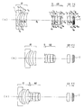
以下、本発明のズームレンズの実施例1〜4について説明する。実施例1〜4の無限遠物点合焦時の広角端(a)、中間状態(b)、望遠端(c)のレンズ断面図をそれぞれ図1〜図4に示す。図1〜図4中、第1レンズ群はG1、開口絞りはS、第2レンズ群はG2、第3レンズ群はG3、赤外光を制限する波長域制限コートを施したローパスフィルタを構成する平行平板はF、CCD、CMOS等の電子撮像素子のカバーガラスの平行平板はC、像面はIで示してある。なお、カバーガラスCの表面に波長域制限用の多層膜を施してもよい。また、そのカバーガラスCにローパスフィルタ作用を持たせるようにしてもよい。 Examples 1 to 4 of the zoom lens according to the present invention will be described below. Lens cross-sectional views of the wide-angle end (a), the intermediate state (b), and the telephoto end (c) when focusing on an object point at infinity in Examples 1 to 4 are shown in FIGS. 1 to 4, the first lens group is G1, the aperture stop is S, the second lens group is G2, the third lens group is G3, and a low-pass filter with a wavelength band limiting coat that limits infrared light is configured. The parallel plate of the cover glass of the electronic image sensor such as F, CCD, or CMOS is indicated by C, and the image plane is indicated by I. In addition, you may give the multilayer film for a wavelength range restriction | limiting to the surface of the cover glass C. FIG. Further, the cover glass C may have a low-pass filter action.
実施例1のズームレンズは、図1に示すように、物体側から順に、負の屈折力の第1レンズ群G1と、開口絞りSと、正屈折力の第2レンズ群G2と、正屈折力の第3レンズ群G3とから構成されており、広角端から望遠端への変倍をする際に、第1レンズ群G1は、物体側に凹の軌跡で移動し、望遠端では広角端の位置より若干像面側に位置し、開口絞りSと第2レンズ群G2は一体に物体側へ単調に移動し、第3レンズ群G3は像面側へ移動する。 As shown in FIG. 1, the zoom lens according to the first exemplary embodiment includes, in order from the object side, a first lens group G1 having a negative refractive power, an aperture stop S, a second lens group G2 having a positive refractive power, and positive refraction. The first lens group G1 moves along a concave locus toward the object side when zooming from the wide-angle end to the telephoto end, and at the telephoto end, the wide-angle end is configured. The aperture stop S and the second lens group G2 are monotonously moved to the object side integrally, and the third lens group G3 is moved to the image plane side.
物体側から順に、第1レンズ群G1は、物体側に凸面を向けた負メニスカスレンズ2枚と、物体側に凸面を向けた正メニスカスレンズとからなり、第2レンズ群G2は、両凸正レンズと、物体側に凸面を向けた正メニスカスレンズと物体側に凸面を向けた負メニスカスレンズの接合レンズと、両凸正レンズとからなり、第3レンズ群G3は、両凸正レンズ1枚からなる。 In order from the object side, the first lens group G1 includes two negative meniscus lenses having a convex surface facing the object side and a positive meniscus lens having a convex surface facing the object side. The second lens group G2 includes a biconvex positive lens. It consists of a lens, a cemented lens of a positive meniscus lens having a convex surface facing the object side, a negative meniscus lens having a convex surface facing the object side, and a biconvex positive lens. The third lens group G3 has one biconvex positive lens. Consists of.
非球面は、第1レンズ群G1の物体側から2番目の負メニスカスレンズの両面、第2レンズ群G2の物体側の両凸正レンズの物体側の面、第3レンズ群G3の両凸正レンズの両面の5面に用いている。 The aspherical surfaces are both surfaces of the second negative meniscus lens from the object side of the first lens group G1, the object side surface of the biconvex positive lens on the object side of the second lens group G2, and the biconvex positive of the third lens group G3. It is used on the 5 sides of the lens.
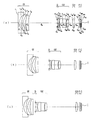
実施例2のズームレンズは、図2に示すように、物体側から順に、負の屈折力の第1レンズ群G1と、開口絞りSと、正屈折力の第2レンズ群G2と、正屈折力の第3レンズ群G3とから構成されており、広角端から望遠端への変倍をする際に、第1レンズ群G1は、物体側に凹の軌跡で移動し、望遠端では広角端の位置より若干像面側に位置し、開口絞りSと第2レンズ群G2は一体に物体側へ単調に移動し、第3レンズ群G3は広角端から中間状態まで像面側へ移動し、中間状態から望遠端までは略固定である。 As shown in FIG. 2, the zoom lens according to the second embodiment includes, in order from the object side, a first lens group G1 having a negative refractive power, an aperture stop S, a second lens group G2 having a positive refractive power, and positive refraction. The first lens group G1 moves along a concave locus toward the object side when zooming from the wide-angle end to the telephoto end, and at the telephoto end, the wide-angle end is configured. The aperture stop S and the second lens group G2 are monotonously moved toward the object side integrally, and the third lens group G3 is moved from the wide-angle end to the intermediate state toward the image plane side. It is substantially fixed from the intermediate state to the telephoto end.
物体側から順に、第1レンズ群G1は、物体側に凸面を向けた負メニスカスレンズ2枚と、物体側に凸面を向けた正メニスカスレンズとからなり、第2レンズ群G2は、両凸正レンズと、物体側に凸面を向けた正メニスカスレンズと物体側に凸面を向けた負メニスカスレンズの接合レンズと、両凸正レンズとからなり、第3レンズ群G3は、両凸正レンズ1枚からなる。 In order from the object side, the first lens group G1 includes two negative meniscus lenses having a convex surface facing the object side and a positive meniscus lens having a convex surface facing the object side. The second lens group G2 includes a biconvex positive lens. It consists of a lens, a cemented lens of a positive meniscus lens having a convex surface facing the object side, a negative meniscus lens having a convex surface facing the object side, and a biconvex positive lens. The third lens group G3 has one biconvex positive lens. Consists of.
非球面は、第1レンズ群G1の物体側から2番目の負メニスカスレンズの両面、第2レンズ群G2の物体側の両凸正レンズの物体側の面、第3レンズ群G3の両凸正レンズの両面の5面に用いている。 The aspherical surfaces are both surfaces of the second negative meniscus lens from the object side of the first lens group G1, the object side surface of the biconvex positive lens on the object side of the second lens group G2, and the biconvex positive of the third lens group G3. It is used on the 5 sides of the lens.
実施例3のズームレンズは、図3に示すように、物体側から順に、負の屈折力の第1レンズ群G1と、開口絞りSと、正屈折力の第2レンズ群G2と、正屈折力の第3レンズ群G3とから構成されており、広角端から望遠端への変倍をする際に、第1レンズ群G1は、物体側に凹の軌跡で移動し、望遠端では広角端の位置より像面側に位置し、開口絞りSと第2レンズ群G2は一体に物体側へ単調に移動し、第3レンズ群G3は像面側へ移動する。 As shown in FIG. 3, the zoom lens of Embodiment 3 includes, in order from the object side, a first lens group G1 having a negative refractive power, an aperture stop S, a second lens group G2 having a positive refractive power, and positive refraction. The first lens group G1 moves along a concave locus toward the object side when zooming from the wide-angle end to the telephoto end, and at the telephoto end, the wide-angle end is configured. The aperture stop S and the second lens group G2 are monotonously moved to the object side integrally, and the third lens group G3 is moved to the image plane side.
物体側から順に、第1レンズ群G1は、物体側に凸面を向けた負メニスカスレンズ2枚と、物体側に凸面を向けた正メニスカスレンズとからなり、第2レンズ群G2は、物体側に凸面を向けた正メニスカスレンズと、物体側に凸面を向けた正メニスカスレンズと物体側に凸面を向けた負メニスカスレンズの接合レンズと、両凸正レンズとからなり、第3レンズ群G3は、両凸正レンズ1枚からなる。 In order from the object side, the first lens group G1 is composed of two negative meniscus lenses having a convex surface facing the object side and a positive meniscus lens having a convex surface facing the object side. The second lens group G2 is disposed on the object side. A positive meniscus lens having a convex surface, a cemented lens of a positive meniscus lens having a convex surface facing the object side, a negative meniscus lens having a convex surface facing the object side, and a biconvex positive lens. The third lens group G3 includes: It consists of one biconvex positive lens.
非球面は、第1レンズ群G1の物体側から2番目の負メニスカスレンズの両面、第2レンズ群G2の正メニスカスレンズの物体側の面、第3レンズ群G3の両凸正レンズの両面の5面に用いている。 The aspheric surfaces are the surfaces of the second negative meniscus lens from the object side of the first lens group G1, the object side surface of the positive meniscus lens of the second lens group G2, and both surfaces of the biconvex positive lens of the third lens group G3. Used on 5 sides.
実施例4のズームレンズは、図4に示すように、物体側から順に、負の屈折力の第1レンズ群G1と、開口絞りSと、正屈折力の第2レンズ群G2と、正屈折力の第3レンズ群G3とから構成されており、広角端から望遠端への変倍をする際に、第1レンズ群G1は、物体側に凹の軌跡で移動し、望遠端では広角端の位置より像面側に位置し、開口絞りSと第2レンズ群G2は一体に物体側へ単調に移動し、第3レンズ群G3は像面側へ移動する。 As shown in FIG. 4, the zoom lens of Example 4 includes, in order from the object side, a first lens group G1 having a negative refractive power, an aperture stop S, a second lens group G2 having a positive refractive power, and positive refraction. The first lens group G1 moves along a concave locus toward the object side when zooming from the wide-angle end to the telephoto end, and at the telephoto end, the wide-angle end is configured. The aperture stop S and the second lens group G2 are monotonously moved to the object side integrally, and the third lens group G3 is moved to the image plane side.
物体側から順に、第1レンズ群G1は、物体側に凸面を向けた負メニスカスレンズ2枚と、物体側に凸面を向けた正メニスカスレンズとからなり、第2レンズ群G2は、両凸正レンズと、物体側に凸面を向けた正メニスカスレンズと物体側に凸面を向けた負メニスカスレンズの接合レンズと、両凸正レンズとからなり、第3レンズ群G3は、両凸正レンズ1枚からなる。 In order from the object side, the first lens group G1 includes two negative meniscus lenses having a convex surface facing the object side and a positive meniscus lens having a convex surface facing the object side. The second lens group G2 includes a biconvex positive lens. It consists of a lens, a cemented lens of a positive meniscus lens having a convex surface facing the object side, a negative meniscus lens having a convex surface facing the object side, and a biconvex positive lens. The third lens group G3 has one biconvex positive lens. Consists of.
非球面は、第1レンズ群G1の物体側から2番目の負メニスカスレンズの両面、第2レンズ群G2の物体側の両凸正レンズの物体側の面、第3レンズ群G3の両凸正レンズの両面の5面に用いている。 The aspherical surfaces are both surfaces of the second negative meniscus lens from the object side of the first lens group G1, the object side surface of the biconvex positive lens on the object side of the second lens group G2, and the biconvex positive of the third lens group G3. It is used on the 5 sides of the lens.
以上の各ズームレンズ共、近距離合焦をレンズ全体若しくは特定のレンズ群の移動にて行うようにしてもよい。また、第3レンズ群のみを移動させると、倍率の変化が抑えられ、移動するレンズも少なく好ましい。 For each of the zoom lenses described above, the short distance focusing may be performed by moving the entire lens or a specific lens group. Further, it is preferable to move only the third lens group, since the change in magnification is suppressed and fewer lenses are moved.
なお、上記実施例1〜4の広角端から望遠端の実画角2ωの範囲は次の通りである。 The range of the actual field angle 2ω from the wide-angle end to the telephoto end in the first to fourth embodiments is as follows.
実施例1 実画角2ω 91.7°〜21.8°
実施例2 実画角2ω 91.7°〜21.7°
実施例3 実画角2ω 91.6°〜22.3°
実施例4 実画角2ω 82.9°〜21.9° 。
Example 1 Actual angle of view 2ω 91.7 ° to 21.8 °
Example 2 Actual angle of view 2ω 91.7 ° to 21.7 °
Example 3 Actual angle of view 2ω 91.6 ° to 22.3 °
Example 4 Actual angle of view 2ω 82.9 ° to 21.9 °.
以下に、上記各実施例の数値データを示すが、記号は上記の外、fは全系焦点距離、FNOはFナンバー、WEは広角端、STは中間状態、TEは望遠端、r1 、r2 …は各レンズ面の曲率半径、d1 、d2 …は各レンズ面間の間隔、nd1、nd2…は各レンズのd線の屈折率、νd1、νd2…は各レンズのアッベ数である。なお、非球面形状は、xを光の進行方向を正とした光軸とし、yを光軸と直交する方向にとると、下記の式にて表される。 In the following, the numerical data of each of the above embodiments is shown. Symbols are the above, f is the total focal length, FNO is the F number, WE is the wide angle end, ST is the intermediate state, TE is the telephoto end, r 1 , r 2 ... curvature radius of each lens surface, d 1, d 2 ... the spacing between the lens surfaces, n d1, n d2 ... d-line refractive index of each lens, ν d1, ν d2 ... each It is the Abbe number of the lens. The aspherical shape is represented by the following formula, where x is an optical axis with the light traveling direction being positive, and y is a direction orthogonal to the optical axis.
x=(y2 /r)/[1+{1−(K+1)(y/r)2 }1/2 ]
+A4 y4 +A6 y6 +A8 y8 +A10y10
ただし、rは近軸曲率半径、Kは円錐係数、A4 、A6 、A8 、A10はそれぞれ4次、6次、8次、10次の非球面係数である。
x = (y 2 / r) / [1+ {1- (K + 1) (y / r) 2 } 1/2 ]
+ A 4 y 4 + A 6 y 6 + A 8 y 8 + A 10 y 10
Here, r is a paraxial radius of curvature, K is a conical coefficient, and A 4 , A 6 , A 8 , and A 10 are fourth-order, sixth-order, eighth-order, and tenth-order aspherical coefficients, respectively.
実施例1
r1 = 120.490 d1 = 1.31 nd1 =1.77250 νd1 =49.60
r2 = 8.803 d2 = 2.41
r3 = 18.045 (非球面) d3 = 1.43 nd2 =1.74330 νd2 =49.33
r4 = 8.094 (非球面) d4 = 3.05
r5 = 14.990 d5 = 2.92 nd3 =1.84666 νd3 =23.78
r6 = 40.520 d6 = (可変)
r7 = ∞(絞り) d7 = 0.50
r8 = 14.360 (非球面) d8 = 1.96 nd4 =1.74330 νd4 =49.33
r9 = -331.278 d9 = 0.37
r10= 12.927 d10= 3.50 nd5 =1.77250 νd5 =49.60
r11= 115.263 d11= 2.37 nd6 =1.84666 νd6 =23.78
r12= 7.486 d12= 0.69
r13= 33.417 d13= 1.95 nd7 =1.48749 νd7 =70.23
r14= -13.786 d14= (可変)
r15= 21.995 (非球面) d15= 2.97 nd8 =1.49700 νd8 =81.54
r16= -21.106 (非球面) d16= (可変)
r17= ∞ d17= 0.76 nd9 =1.54771 νd9 =62.84
r18= ∞ d18= 0.44
r19= ∞ d19= 0.40 nd10=1.51633 νd10=64.14
r20= ∞ d20= 0.60
r21= ∞(像面)
非球面係数
第3面
K = -2.076
A4 = 6.45927×10⁻⁵
A6 = 6.49359×10⁻⁶
A8 = -8.75295×10⁻⁸
A10= 3.45632×10⁻¹⁰
第4面
K = -0.123
A4 = -2.45406×10⁻⁴
A6 = 6.68743×10⁻⁶
A8 = -1.43236×10⁻⁷
A10= -2.58394×10⁻¹⁰
第8面
K = -2.842
A4 = 5.45802×10⁻⁵
A6 = -8.40498×10⁻⁷
A8 = 3.93728×10⁻⁸
A10= -8.90443×10⁻¹⁰
第15面
K = 17.207
A4 = -4.08931×10⁻⁴
A6 = 3.36877×10⁻⁵
A8 = -1.34835×10⁻⁶
A10= 1.83688×10⁻⁸
第16面
K = -5.667
A4 = -2.68421×10⁻⁴
A6 = 8.59656×10⁻⁵
A8 = -4.00016×10⁻⁶
A10= 9.20195×10⁻⁸
ズームデータ(∞)
WE ST TE
f (mm) 3.991 8.545 18.189
FNO 2.80 3.67 4.80
d6 26.79 9.98 2.08
d14 5.33 12.90 28.33
d16 2.41 2.20 1.98 。
Example 1
r 1 = 120.490 d 1 = 1.31 n d1 = 1.77250 ν d1 = 49.60
r 2 = 8.803 d 2 = 2.41
r 3 = 18.045 (aspherical surface) d 3 = 1.43 n d2 = 1.74330 ν d2 = 49.33
r 4 = 8.094 (aspherical surface) d 4 = 3.05
r 5 = 14.990 d 5 = 2.92 n d3 = 1.84666 ν d3 = 23.78
r 6 = 40.520 d 6 = (variable)
r 7 = ∞ (aperture) d 7 = 0.50
r 8 = 14.360 (aspherical surface) d 8 = 1.96 n d4 = 1.74330 ν d4 = 49.33
r 9 = -331.278 d 9 = 0.37
r 10 = 12.927 d 10 = 3.50 n d5 = 1.77250 ν d5 = 49.60
r 11 = 115.263 d 11 = 2.37 n d6 = 1.84666 ν d6 = 23.78
r 12 = 7.486 d 12 = 0.69
r 13 = 33.417 d 13 = 1.95 n d7 = 1.48749 ν d7 = 70.23
r 14 = -13.786 d 14 = (variable)
r 15 = 21.995 (aspherical surface) d 15 = 2.97 n d8 = 1.49700 ν d8 = 81.54
r 16 = -21.106 (aspherical surface) d 16 = (variable)
r 17 = ∞ d 17 = 0.76 n d9 = 1.54771 ν d9 = 62.84
r 18 = ∞ d 18 = 0.44
r 19 = ∞ d 19 = 0.40 n d10 = 1.51633 ν d10 = 64.14
r 20 = ∞ d 20 = 0.60
r 21 = ∞ (image plane)
Aspheric coefficient 3rd surface K = -2.076
A 4 = 6.45927 × 10 -5
A 6 = 6.49359 × 10 -6
A 8 = -8.75295 × 10 -8
A 10 = 3.45632 × 10 -10
4th surface K = -0.123
A 4 = -2.45406 × 10 -4
A 6 = 6.68743 × 10 -6
A 8 = -1.43236 × 10 -7
A 10 = -2.58394 × 10 -10
Surface 8 K = -2.842
A 4 = 5.45802 × 10 -5
A 6 = -8.40498 × 10 -7
A 8 = 3.93728 × 10 -8
A 10 = -8.90443 × 10 -10
Surface 15 K = 17.207
A 4 = -4.08931 × 10 -4
A 6 = 3.36877 × 10 -5
A 8 = -1.34835 × 10 -6
A 10 = 1.83688 × 10 -8
16th surface K = -5.667
A 4 = -2.68421 × 10 -4
A 6 = 8.59656 × 10 -5
A 8 = -4.00016 × 10 -6
A 10 = 9.20195 × 10 -8
Zoom data (∞)
WE ST TE
f (mm) 3.991 8.545 18.189
F NO 2.80 3.67 4.80
d 6 26.79 9.98 2.08
d 14 5.33 12.90 28.33
d 16 2.41 2.20 1.98.
実施例2
r1 = 118.807 d1 = 1.31 nd1 =1.77250 νd1 =49.60
r2 = 8.809 d2 = 2.41
r3 = 18.035 (非球面) d3 = 1.39 nd2 =1.74330 νd2 =49.33
r4 = 7.941 (非球面) d4 = 3.10
r5 = 15.161 d5 = 3.00 nd3 =1.84666 νd3 =23.78
r6 = 44.116 d6 = (可変)
r7 = ∞(絞り) d7 = 0.50
r8 = 12.553 (非球面) d8 = 2.00 nd4 =1.74330 νd4 =49.33
r9 = -1072.915 d9 = 0.47
r10= 14.652 d10= 2.88 nd5 =1.77250 νd5 =49.60
r11= 116.690 d11= 2.58 nd6 =1.84666 νd6 =23.78
r12= 7.579 d12= 0.66
r13= 28.801 d13= 1.98 nd7 =1.48749 νd7 =70.23
r14= -13.779 d14= (可変)
r15= 25.196 (非球面) d15= 3.23 nd8 =1.49700 νd8 =81.54
r16= -20.772 (非球面) d16= (可変)
r17= ∞ d17= 0.76 nd9 =1.54771 νd9 =62.84
r18= ∞ d18= 0.44
r19= ∞ d19= 0.40 nd10=1.51633 νd10=64.14
r20= ∞ d20= 0.60
r21= ∞(像面)
非球面係数
第3面
K = -2.753
A4 = 5.55177×10⁻⁵
A6 = 6.78542×10⁻⁶
A8 = -8.75312×10⁻⁸
A10= 3.00839×10⁻¹⁰
第4面
K = -0.154
A4 = -2.78544×10⁻⁴
A6 = 7.01729×10⁻⁶
A8 = -1.42051×10⁻⁷
A10= -3.59350×10⁻¹⁰
第8面
K = -2.029
A4 = 4.38908×10⁻⁵
A6 = -2.45433×10⁻⁷
A8 = -8.67387×10⁻⁹
A10= 4.57999×10⁻¹⁰
第15面
K = 26.077
A4 = -4.19155×10⁻⁴
A6 = 3.06327×10⁻⁵
A8 = -1.13473×10⁻⁶
A10= 3.54518×10⁻⁹
第16面
K = -3.248
A4 = -2.66612×10⁻⁴
A6 = 8.09076×10⁻⁵
A8 = -3.64091×10⁻⁶
A10= 7.64667×10⁻⁸
ズームデータ(∞)
WE ST TE
f (mm) 3.990 8.545 18.288
FNO 2.80 3.67 4.80
d6 26.74 9.60 1.50
d14 5.18 12.57 28.03
d16 2.52 2.40 2.40 。
Example 2
r 1 = 118.807 d 1 = 1.31 n d1 = 1.77250 ν d1 = 49.60
r 2 = 8.809 d 2 = 2.41
r 3 = 18.035 (aspherical surface) d 3 = 1.39 n d2 = 1.74330 ν d2 = 49.33
r 4 = 7.941 (aspherical surface) d 4 = 3.10
r 5 = 15.161 d 5 = 3.00 n d3 = 1.84666 ν d3 = 23.78
r 6 = 44.116 d 6 = (variable)
r 7 = ∞ (aperture) d 7 = 0.50
r 8 = 12.553 (aspherical surface) d 8 = 2.00 n d4 = 1.74330 ν d4 = 49.33
r 9 = -1072.915 d 9 = 0.47
r 10 = 14.652 d 10 = 2.88 n d5 = 1.77250 ν d5 = 49.60
r 11 = 116.690 d 11 = 2.58 n d6 = 1.84666 ν d6 = 23.78
r 12 = 7.579 d 12 = 0.66
r 13 = 28.801 d 13 = 1.98 n d7 = 1.48749 ν d7 = 70.23
r 14 = -13.779 d 14 = (variable)
r 15 = 25.196 (aspherical surface) d 15 = 3.23 n d8 = 1.49700 ν d8 = 81.54
r 16 = -20.772 (aspherical surface) d 16 = (variable)
r 17 = ∞ d 17 = 0.76 n d9 = 1.54771 ν d9 = 62.84
r 18 = ∞ d 18 = 0.44
r 19 = ∞ d 19 = 0.40 n d10 = 1.51633 ν d10 = 64.14
r 20 = ∞ d 20 = 0.60
r 21 = ∞ (image plane)
Aspheric coefficient 3rd surface K = -2.753
A 4 = 5.55177 × 10 -5
A 6 = 6.78542 × 10 -6
A 8 = -8.75312 × 10 -8
A 10 = 3.00839 × 10 -10
4th surface K = -0.154
A 4 = -2.78544 × 10 -4
A 6 = 7.01729 × 10 -6
A 8 = -1.42051 × 10 -7
A 10 = -3.59350 × 10 -10
Surface 8 K = -2.029
A 4 = 4.38908 × 10 -5
A 6 = -2.45433 × 10 -7
A 8 = -8.67387 × 10 -9
A 10 = 4.57999 × 10 -10
Surface 15 K = 26.077
A 4 = -4.19155 × 10 -4
A 6 = 3.06327 × 10 -5
A 8 = -1.13473 × 10 -6
A 10 = 3.54518 × 10 -9
16th surface K = -3.248
A 4 = -2.66612 × 10 -4
A 6 = 8.09076 × 10 -5
A 8 = -3.64091 × 10 -6
A 10 = 7.64667 × 10 -8
Zoom data (∞)
WE ST TE
f (mm) 3.990 8.545 18.288
F NO 2.80 3.67 4.80
d 6 26.74 9.60 1.50
d 14 5.18 12.57 28.03
d 16 2.52 2.40 2.40.
実施例3
r1 = 4500.383 d1 = 1.32 nd1 =1.77250 νd1 =49.60
r2 = 9.359 d2 = 2.41
r3 = 24.524 (非球面) d3 = 1.39 nd2 =1.74330 νd2 =49.33
r4 = 8.963 (非球面) d4 = 2.41
r5 = 17.943 d5 = 2.89 nd3 =1.84666 νd3 =23.78
r6 = 284.297 d6 = (可変)
r7 = ∞(絞り) d7 = 0.50
r8 = 19.436 (非球面) d8 = 1.53 nd4 =1.74330 νd4 =49.33
r9 = 137.997 d9 = 0.18
r10= 11.381 d10= 3.19 nd5 =1.77250 νd5 =49.60
r11= 4390.531 d11= 3.25 nd6 =1.84666 νd6 =23.78
r12= 8.260 d12= 0.69
r13= 26.872 d13= 2.09 nd7 =1.48749 νd7 =70.23
r14= -12.935 d14= (可変)
r15= 24.500 (非球面) d15= 1.90 nd8 =1.49700 νd8 =81.54
r16= -24.796 (非球面) d16= (可変)
r17= ∞ d17= 0.76 nd9 =1.54771 νd9 =62.84
r18= ∞ d18= 0.44
r19= ∞ d19= 0.40 nd10=1.51633 νd10=64.14
r20= ∞ d20= 0.60
r21= ∞(像面)
非球面係数
第3面
K = 0.000
A4 = -1.09346×10⁻²²
A6 = 7.42289×10⁻⁶
A8 = -8.34361×10⁻⁸
A10= 2.82193×10⁻¹⁰
第4面
K = -0.145
A4 = -2.76977×10⁻⁴
A6 = 8.02851×10⁻⁶
A8 = -1.22644×10⁻⁷
A10= -8.03256×10⁻¹³
第8面
K = -4.326
A4 = 3.58731×10⁻⁶
A6 = 1.37882×10⁻⁶
A8 = -1.18290×10⁻⁷
A10= 3.57210×10⁻⁹
第15面
K = 27.818
A4 = -5.16300×10⁻⁴
A6 = -6.63410×10⁻⁷
A8 = -1.73194×10⁻⁶
A10= -5.52968×10⁻¹⁰
第16面
K = 0.000
A4 = -2.87839×10⁻⁴
A6 = 4.85820×10⁻⁵
A8 = -5.34160×10⁻⁶
A10= 1.27186×10⁻⁷
ズームデータ(∞)
WE ST TE
f (mm) 3.995 8.550 17.995
FNO 2.77 3.36 4.83
d6 27.65 10.79 2.05
d14 3.80 13.22 27.89
d16 4.77 3.08 1.86 。
Example 3
r 1 = 4500.383 d 1 = 1.32 n d1 = 1.77250 ν d1 = 49.60
r 2 = 9.359 d 2 = 2.41
r 3 = 24.524 (aspherical surface) d 3 = 1.39 n d2 = 1.74330 ν d2 = 49.33
r 4 = 8.963 (aspherical surface) d 4 = 2.41
r 5 = 17.943 d 5 = 2.89 n d3 = 1.84666 ν d3 = 23.78
r 6 = 284.297 d 6 = (variable)
r 7 = ∞ (aperture) d 7 = 0.50
r 8 = 19.436 (aspherical surface) d 8 = 1.53 n d4 = 1.74330 ν d4 = 49.33
r 9 = 137.997 d 9 = 0.18
r 10 = 11.381 d 10 = 3.19 n d5 = 1.77250 ν d5 = 49.60
r 11 = 4390.531 d 11 = 3.25 n d6 = 1.84666 ν d6 = 23.78
r 12 = 8.260 d 12 = 0.69
r 13 = 26.872 d 13 = 2.09 n d7 = 1.48749 ν d7 = 70.23
r 14 = -12.935 d 14 = (variable)
r 15 = 24.500 (aspherical surface) d 15 = 1.90 n d8 = 1.49700 ν d8 = 81.54
r 16 = -24.796 (aspherical surface) d 16 = (variable)
r 17 = ∞ d 17 = 0.76 n d9 = 1.54771 ν d9 = 62.84
r 18 = ∞ d 18 = 0.44
r 19 = ∞ d 19 = 0.40 n d10 = 1.51633 ν d10 = 64.14
r 20 = ∞ d 20 = 0.60
r 21 = ∞ (image plane)
Aspheric coefficient 3rd surface K = 0.000
A 4 = -1.09346 × 10 -22
A 6 = 7.42289 × 10 -6
A 8 = -8.34361 × 10 -8
A 10 = 2.82193 × 10 -10
4th surface K = -0.145
A 4 = -2.76977 × 10 -4
A 6 = 8.02851 × 10 -6
A 8 = -1.22644 × 10 -7
A 10 = -8.03256 × 10 -13
Surface 8 K = -4.326
A 4 = 3.58731 × 10 -6
A 6 = 1.37882 × 10 -6
A 8 = -1.18290 × 10 -7
A 10 = 3.57210 × 10 -9
Surface 15 K = 27.818
A 4 = -5.16300 × 10 -4
A 6 = -6.63410 × 10 -7
A 8 = -1.73194 × 10 -6
A 10 = -5.52968 × 10 -10
16th surface K = 0.000
A 4 = -2.87839 × 10 -4
A 6 = 4.85820 × 10 -5
A 8 = -5.34160 × 10 -6
A 10 = 1.27186 × 10 -7
Zoom data (∞)
WE ST TE
f (mm) 3.995 8.550 17.995
F NO 2.77 3.36 4.83
d 6 27.65 10.79 2.05
d 14 3.80 13.22 27.89
d 16 4.77 3.08 1.86.
実施例4
r1 = 121.056 d1 = 1.43 nd1 =1.77250 νd1 =49.60
r2 = 9.380 d2 = 2.15
r3 = 16.015 (非球面) d3 = 1.44 nd2 =1.74330 νd2 =49.33
r4 = 8.193 (非球面) d4 = 2.98
r5 = 16.120 d5 = 2.94 nd3 =1.84666 νd3 =23.78
r6 = 45.014 d6 = (可変)
r7 = ∞(絞り) d7 = 0.47
r8 = 14.773 (非球面) d8 = 1.86 nd4 =1.74330 νd4 =49.33
r9 = -994.295 d9 = 0.33
r10= 13.147 d10= 2.82 nd5 =1.77250 νd5 =49.60
r11= 72.079 d11= 2.42 nd6 =1.84666 νd6 =23.78
r12= 8.130 d12= 0.66
r13= 29.342 d13= 1.71 nd7 =1.48749 νd7 =70.23
r14= -16.090 d14= (可変)
r15= 25.866 (非球面) d15= 2.62 nd8 =1.49700 νd8 =81.54
r16= -21.997 (非球面) d16= (可変)
r17= ∞ d17= 0.76 nd9 =1.54771 νd9 =62.84
r18= ∞ d18= 0.44
r19= ∞ d19= 0.40 nd10=1.51633 νd10=64.14
r20= ∞ d20= 0.60
r21= ∞(像面)
非球面係数
第3面
K = -8.593
A4 = -5.21721×10⁻⁵
A6 = 1.35472×10⁻⁵
A8 = -1.60073×10⁻⁷
A10= 8.18893×10⁻¹⁰
第4面
K = -0.267
A4 = -5.36622×10⁻⁴
A6 = 1.87785×10⁻⁵
A8 = -2.34186×10⁻⁷
A10= 6.47476×10⁻¹⁰
第8面
K = -2.764
A4 = 3.65365×10⁻⁵
A6 = 1.70796×10⁻⁶
A8 = -1.47291×10⁻⁷
A10= 4.47653×10⁻⁹
第15面
K = 31.103
A4 = -5.88505×10⁻⁴
A6 = 5.86985×10⁻⁶
A8 = -6.62903×10⁻⁷
A10= 3.27987×10⁻⁹
第16面
K = -3.969
A4 = -6.53373×10⁻⁴
A6 = 9.42874×10⁻⁵
A8 = -6.79301×10⁻⁶
A10= 1.91081×10⁻⁷
ズームデータ(∞)
WE ST TE
f (mm) 4.460 9.095 18.274
FNO 2.80 3.67 4.80
d6 26.31 10.64 2.46
d14 5.71 13.58 26.94
d16 3.41 2.53 2.23 。
Example 4
r 1 = 121.056 d 1 = 1.43 n d1 = 1.77250 ν d1 = 49.60
r 2 = 9.380 d 2 = 2.15
r 3 = 16.015 (aspherical surface) d 3 = 1.44 n d2 = 1.74330 ν d2 = 49.33
r 4 = 8.193 (aspherical surface) d 4 = 2.98
r 5 = 16.120 d 5 = 2.94 n d3 = 1.84666 ν d3 = 23.78
r 6 = 45.014 d 6 = (variable)
r 7 = ∞ (aperture) d 7 = 0.47
r 8 = 14.773 (aspherical surface) d 8 = 1.86 n d4 = 1.74330 ν d4 = 49.33
r 9 = -994.295 d 9 = 0.33
r 10 = 13.147 d 10 = 2.82 n d5 = 1.77250 ν d5 = 49.60
r 11 = 72.079 d 11 = 2.42 n d6 = 1.84666 ν d6 = 23.78
r 12 = 8.130 d 12 = 0.66
r 13 = 29.342 d 13 = 1.71 n d7 = 1.48749 ν d7 = 70.23
r 14 = -16.090 d 14 = (variable)
r 15 = 25.866 (aspherical surface) d 15 = 2.62 n d8 = 1.49700 ν d8 = 81.54
r 16 = -21.997 (aspherical surface) d 16 = (variable)
r 17 = ∞ d 17 = 0.76 n d9 = 1.54771 ν d9 = 62.84
r 18 = ∞ d 18 = 0.44
r 19 = ∞ d 19 = 0.40 n d10 = 1.51633 ν d10 = 64.14
r 20 = ∞ d 20 = 0.60
r 21 = ∞ (image plane)
Aspheric coefficient 3rd surface K = -8.593
A 4 = -5.21721 × 10 -5
A 6 = 1.35472 × 10 -5
A 8 = -1.60073 × 10 -7
A 10 = 8.18893 × 10 -10
4th surface K = -0.267
A 4 = -5.36622 × 10 -4
A 6 = 1.87785 × 10 -5
A 8 = -2.34186 × 10 -7
A 10 = 6.47476 × 10 -10
Surface 8 K = -2.764
A 4 = 3.65365 × 10 -5
A 6 = 1.70796 × 10 -6
A 8 = -1.47291 × 10 -7
A 10 = 4.47653 × 10 -9
15th surface K = 31.103
A 4 = -5.88505 × 10 -4
A 6 = 5.86985 × 10 -6
A 8 = -6.62903 × 10 -7
A 10 = 3.27987 × 10 -9
16th surface K = -3.969
A 4 = -6.53373 × 10 -4
A 6 = 9.42874 × 10 -5
A 8 = -6.79301 × 10 -6
A 10 = 1.91081 × 10 -7
Zoom data (∞)
WE ST TE
f (mm) 4.460 9.095 18.274
F NO 2.80 3.67 4.80
d 6 26.31 10.64 2.46
d 14 5.71 13.58 26.94
d 16 3.41 2.53 2.23.
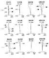
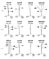
以上の実施例1〜4の無限遠物点合焦時の収差図をそれぞれ図5〜図8に示す。これらの収差図において、(a)は広角端、(b)は中間状態、(c)は望遠端における球面収差、非点収差、歪曲収差、倍率色収差を示す。各図中、“FIY”は最大像高を示す。 Aberration diagrams at the time of focusing on an object point at infinity in Examples 1 to 4 are shown in FIGS. In these aberration diagrams, (a) is a wide-angle end, (b) is an intermediate state, and (c) is spherical aberration, astigmatism, distortion, and lateral chromatic aberration at a telephoto end. In each figure, “FIY” indicates the maximum image height.
次に、上記各実施例における画角、条件式(1)〜(10)の値、及び、IH、fw 、ft 、da 、db 、fra、fra/IH、frb、frb/fra、f1G、f2G、r1 、r21、r22、HB1 、HD12w 、TLw の値を示す。 Then, the angle in the above embodiment, the value of the conditional expression (1) to (10), and, IH, f w, f t , d a, d b, f ra, f ra / IH, f rb, The values of f rb / f ra , f 1G , f 2G , r 1 , r 21 , r 22 , HB 1 , HD 12w , and TL w are shown.
実施例1 実施例2 実施例3 実施例4
条件式(1) 0.902 0.902 0.901 0.807
条件式(2) 4.558 4.583 4.504 4.097
条件式(3) 2.315 2.301 2.169 2.035
条件式(4) 0.145 0.104 0.135 0.167
条件式(5) 0.0299 0.0303 0.0008 0.0297
条件式(6) -0.917 -0.977 -1.328 -0.971
条件式(7) 0.424 0.412 0.399 0.440
条件式(8) 3.598 3.599 3.797 3.309
条件式(9) 0.104 0.103 0.098 0.106
条件式(10) 15.57 15.58 15.56 13.78
条件式(11) 2.899 2.912 3.191 2.899
IH 3.60 3.60 3.60 3.60
fw 3.991 3.990 3.995 4.460
ft 18.189 18.288 17.995 18.274
da 26.79 26.74 27.65 26.31
db 2.08 1.50 2.05 2.46
fra(広角端時焦点距離を選択) 3.991 3.990 3.995 4.460
fra/IH 1.109 1.108 1.110 1.239
frb(望遠端時焦点距離を選択) 18.189 18.288 17.995 18.274
frb/fra 4.557 4.583 4.504 4.097
f1G -11.57 -11.62 -12.75 -12.93
f2G 14.36 14.36 15.17 14.76
r1 120.490 118.807 4500.383 121.056
r21 14.36 12.553 19.436 14.773
r22 -331.278 -1072.915 137.997 -994.295
HB1 8.49 8.73 9.02 8.18
HD12w 34.68 35.08 36.92 34.06
TLw 62.15 62.15 62.17 61.45
。
Example 1 Example 2 Example 3 Example 4
Conditional expression (1) 0.902 0.902 0.901 0.807
Conditional expression (2) 4.558 4.583 4.504 4.097
Conditional expression (3) 2.315 2.301 2.169 2.035
Conditional expression (4) 0.145 0.104 0.135 0.167
Conditional expression (5) 0.0299 0.0303 0.0008 0.0297
Conditional expression (6) -0.917 -0.977 -1.328 -0.971
Conditional expression (7) 0.424 0.412 0.399 0.440
Conditional expression (8) 3.598 3.599 3.797 3.309
Conditional expression (9) 0.104 0.103 0.098 0.106
Conditional expression (10) 15.57 15.58 15.56 13.78
Conditional expression (11) 2.899 2.912 3.191 2.899
IH 3.60 3.60 3.60 3.60
f w 3.991 3.990 3.995 4.460
f t 18.189 18.288 17.995 18.274
d a 26.79 26.74 27.65 26.31
d b 2.08 1.50 2.05 2.46
f ra (Select focal length at wide angle end) 3.991 3.990 3.995 4.460
f ra / IH 1.109 1.108 1.110 1.239
f rb (Select the focal length at the telephoto end) 18.189 18.288 17.995 18.274
f rb / f ra 4.557 4.583 4.504 4.097
f 1G -11.57 -11.62 -12.75 -12.93
f 2G 14.36 14.36 15.17 14.76
r 1 120.490 118.807 4500.383 121.056
r 21 14.36 12.553 19.436 14.773
r 22 -331.278 -1072.915 137.997 -994.295
HB 1 8.49 8.73 9.02 8.18
HD 12w 34.68 35.08 36.92 34.06
TL w 62.15 62.15 62.17 61.45
.
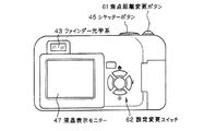
図9〜図11は、以上のようなズームレンズを撮影光学系41に組み込んだ本発明によるデジタルカメラの構成の概念図を示す。図9はデジタルカメラ40の外観を示す前方斜視図、図10は同後方正面図、図11はデジタルカメラ40の構成を示す模式的な断面図である。ただし、図9と図11においては、撮影光学系41の非沈胴時を示している。デジタルカメラ40は、この例の場合、撮影用光路42を有する撮影光学系41、ファインダー用光路44を有するファインダー光学系43、シャッターボタン45、フラッシュ46、液晶表示モニター47、焦点距離変更ボタン61、設定変更スイッチ62等を含み、撮影光学系41の沈胴時には、カバー60をスライドすることにより、撮影光学系41とファインダー光学系43とフラッシュ46はそのカバー60で覆われる。そして、カバー60を開いてカメラ40を撮影状態に設定すると、撮影光学系41は図11の非沈胴状態になり、カメラ40の上部に配置されたシャッターボタン45を押圧すると、それに連動して撮影光学系41、例えば実施例1のズームレンズを通して撮影が行われる。撮影光学系41によって形成された物体像が、波長域制限コートを施したローパスフィルタFとカバーガラスCを介してCCD49の撮像面(光電変換面)上に形成される。このCCD49で受光された物体像は、処理手段51を介し、電子画像としてカメラ背面に設けられた液晶表示モニター47に表示される。また、この処理手段51には記録手段52が接続され、撮影された電子画像を記録することもできる。なお、この記録手段52は処理手段51と別体に設けてもよいし、フロッピーディスクやメモリーカード、MO等により電子的に記録書込を行うように構成してもよい。また、CCD49に代わって銀塩フィルムを配置した銀塩カメラとして構成してもよい。
9 to 11 are conceptual diagrams of the configuration of the digital camera according to the present invention in which the zoom lens as described above is incorporated in the photographing optical system 41. FIG. 9 is a front perspective view showing the appearance of the digital camera 40, FIG. 10 is a rear front view thereof, and FIG. 11 is a schematic cross-sectional view showing the configuration of the digital camera 40. However, FIGS. 9 and 11 show a state in which the photographing optical system 41 is not retracted. In this example, the digital camera 40 includes a photographing optical system 41 having a photographing optical path 42, a finder optical system 43 having a finder optical path 44, a shutter button 45, a flash 46, a liquid crystal display monitor 47, a focal length change button 61, When the photographing optical system 41 is retracted, including the setting change switch 62, the photographing optical system 41, the finder optical system 43, and the flash 46 are covered with the cover 60 by sliding the cover 60. When the cover 60 is opened and the camera 40 is set to the photographing state, the photographing optical system 41 is brought into the non-collapsed state of FIG. 11, and when the shutter button 45 disposed on the upper part of the camera 40 is pressed, the photographing is performed in conjunction therewith. Photographing is performed through the optical system 41, for example, the zoom lens of the first embodiment. An object image formed by the photographic optical system 41 is formed on the imaging surface (photoelectric conversion surface) of the
さらに、ファインダー用光路44上にはファインダー用対物光学系53が配置してある。ファインダー用対物光学系53は、複数のレンズ群(図の場合は3群)と2つのプリズムからなり、撮影光学系41のズームレンズに連動して焦点距離が変化するズーム光学系からなり、このファインダー用対物光学系53によって形成された物体像は、像正立部材である正立プリズム55の視野枠57上に形成される。この正立プリズム55の後方には、正立正像にされた像を観察者眼球Eに導く接眼光学系59が配置されている。なお、接眼光学系59の射出側にカバー部材50が配置されている。 Further, a finder objective optical system 53 is disposed on the finder optical path 44. The finder objective optical system 53 includes a plurality of lens groups (three groups in the figure) and two prisms, and includes a zoom optical system whose focal length changes in conjunction with the zoom lens of the photographing optical system 41. The object image formed by the finder objective optical system 53 is formed on the field frame 57 of the erecting prism 55 that is an image erecting member. Behind the erecting prism 55, an eyepiece optical system 59 for guiding the erect image to the observer eyeball E is disposed. A cover member 50 is disposed on the exit side of the eyepiece optical system 59.
このように構成されたデジタルカメラ40は、撮影光学系41が、本発明により、十分な広角域を有し、コンパクトな構成としながら、高変倍で全変倍域で結像性能を極めて安定的であるあるので、高性能・小型化・広角化が実現できる。 In the digital camera 40 configured in this way, the imaging optical system 41 has a sufficiently wide angle range and a compact configuration according to the present invention. Therefore, high performance, small size, and wide angle can be realized.
本発明は、以上のような一般的な被写体を撮影する所謂コンパクトデジタルカメラだけでなく、広い画角が必要な監視カメラや、レンズ交換式のカメラに適用してもよい。 The present invention may be applied not only to a so-called compact digital camera that captures a general subject as described above, but also to a surveillance camera that requires a wide angle of view and an interchangeable lens camera.
G1…第1レンズ群
G2…第2レンズ群
G3…第3レンズ群
S…開口絞り
F…ローパスフィルタ
C…カバーガラス
I…像面
E…観察者眼球
40…デジタルカメラ
41…撮影光学系
42…撮影用光路
43…ファインダー光学系
44…ファインダー用光路
45…シャッターボタン
46…フラッシュ
47…液晶表示モニター
49…CCD
50…カバー部材
51…処理手段
52…記録手段
53…ファインダー用対物光学系
55…正立プリズム
57…視野枠
59…接眼光学系
60…カバー
61…焦点距離変更ボタン
62…設定変更スイッチ
G1 ... 1st lens group G2 ... 2nd lens group G3 ... 3rd lens group S ... Aperture stop F ... Low pass filter C ... Cover glass I ... Image plane E ... Observer eyeball 40 ... Digital camera 41 ... Shooting optical system 42 ... Optical path for photographing 43 ... finder optical system 44 ... optical path for finder 45 ... shutter button 46 ... flash 47 ... liquid crystal display monitor 49 ... CCD
DESCRIPTION OF SYMBOLS 50 ... Cover member 51 ... Processing means 52 ... Recording means 53 ... Viewfinder objective optical system 55 ... Erect prism 57 ... Field frame 59 ... Eyepiece optical system 60 ... Cover 61 ... Focal length change button 62 ... Setting change switch
Claims (20)
0.80<IH/fw <1.5 ・・・(1)
2.7<ft /fw <12 ・・・(2)
0.05<|da /f1G|<10 ・・・(3)
0<db /f2G<3 ・・・(4)
ただし、IHはズームレンズの撮影像高、
fw はズームレンズ全系の広角端での焦点距離、
ft はズームレンズ全系の望遠端での焦点距離、
f1Gは第1レンズ群の焦点距離、
f2Gは第2レンズ群の焦点距離、
da は、ズームレンズ全系が以下の条件(a)を満足する何れかの焦点距離fraのときの第1レンズ群と第2レンズ群との軸上間隔、
IH/0.92<fra<IH/0.8 ・・・(a)
db は、ズームレンズ全系が以下の条件(b)を満足する何れかの焦点距離frbのときの第1レンズ群と第2レンズ群との軸上間隔、
2.7<frb/fra<5 ・・・(b)
である。 In order from the object side, there are a first lens unit with negative refracting power, a second lens group with positive refracting power, and a third lens group with positive refracting power. A zoom lens satisfying the expressions (1) to (4).
0.80 <IH / f w <1.5 (1)
2.7 < ft / fw <12 (2)
0.05 <| d a / f 1G | <10 (3)
0 <d b / f 2G <3 (4)
Where IH is the image height of the zoom lens,
f w is the focal length at the wide-angle end of the entire zoom lens system,
f t is the focal length at the telephoto end of the entire zoom lens system,
f 1G is the focal length of the first lens group,
f 2G is the focal length of the second lens group,
d a is the axial distance between the first lens group and the second lens group when the entire zoom lens system has any focal length f ra that satisfies the following condition (a):
IH / 0.92 <f ra <IH / 0.8 (a)
d b is the axial distance between the first lens group and the second lens group when the entire zoom lens system has any focal length fr that satisfies the following condition (b):
2.7 <f rb / f ra <5 (b)
It is.
−0.07<IH/r1 <0.07 ・・・(5)
ただし、r1 は第1レンズ群中の最も物体側のレンズ面の近軸曲率半径、
である。 2. The zoom lens according to claim 1, wherein the following conditional expression (5) is satisfied.
−0.07 <IH / r 1 <0.07 (5)
Where r 1 is the paraxial radius of curvature of the most object side lens surface in the first lens group,
It is.
−0.015<IH/r1 <0.04 ・・・(5’) 3. The zoom lens according to claim 2, wherein the following conditional expression (5 ′) is satisfied instead of conditional expression (5).
−0.015 <IH / r 1 <0.04 (5 ′)
−8<(r21+r22)/(r21−r22)<0 ・・・(6)
ただし、レンズ成分は、物体側面と像側面が空気に接触し、それらの面間に空間を持たないレンズ、つまり、単レンズ又は接合レンズとし、
r21は前記正レンズ成分の物体側面の近軸曲率半径、
r22は前記正レンズ成分の像側面の近軸曲率半径、
である。 16. The zoom lens according to claim 1, wherein the second lens group has a positive lens component closest to the object side, and the positive lens component satisfies the following conditional expression. Zoom lens.
−8 <(r 21 + r 22 ) / (r 21 −r 22 ) <0 (6)
However, the lens component is a lens in which the object side surface and the image side surface are in contact with air and there is no space between those surfaces, that is, a single lens or a cemented lens,
r 21 is the paraxial radius of curvature of the object side surface of the positive lens component,
r 22 is the paraxial radius of curvature of the image side surface of the positive lens component,
It is.
−2<(r21+r22)/(r21−r22)<−0.5 ・・・(6’) The zoom lens according to claim 16, wherein the following conditional expression (6 ') is satisfied instead of conditional expression (6).
−2 <(r 21 + r 22 ) / (r 21 −r 22 ) <− 0.5 (6 ′)
。 20. An electronic image pickup apparatus comprising a zoom lens and an electronic image pickup device that is disposed on an image side of the zoom lens and converts an optical image into an electric signal, wherein the zoom lens is according to claim 1. An electronic imaging apparatus, characterized by being a zoom lens.
.
Priority Applications (2)
| Application Number | Priority Date | Filing Date | Title |
|---|---|---|---|
| JP2005120742A JP2006301154A (en) | 2005-04-19 | 2005-04-19 | Zoom lens and electronic imaging apparatus using the same |
| US11/406,297 US7336428B2 (en) | 2005-04-19 | 2006-04-19 | Zoom lens system and electronic image pickup apparatus using the same |
Applications Claiming Priority (1)
| Application Number | Priority Date | Filing Date | Title |
|---|---|---|---|
| JP2005120742A JP2006301154A (en) | 2005-04-19 | 2005-04-19 | Zoom lens and electronic imaging apparatus using the same |
Publications (2)
| Publication Number | Publication Date |
|---|---|
| JP2006301154A true JP2006301154A (en) | 2006-11-02 |
| JP2006301154A5 JP2006301154A5 (en) | 2008-04-03 |
Family
ID=37469535
Family Applications (1)
| Application Number | Title | Priority Date | Filing Date |
|---|---|---|---|
| JP2005120742A Pending JP2006301154A (en) | 2005-04-19 | 2005-04-19 | Zoom lens and electronic imaging apparatus using the same |
Country Status (1)
| Country | Link |
|---|---|
| JP (1) | JP2006301154A (en) |
Cited By (12)
| Publication number | Priority date | Publication date | Assignee | Title |
|---|---|---|---|---|
| JP2009244473A (en) * | 2008-03-31 | 2009-10-22 | Hoya Corp | Zoom lens system and electronic imaging apparatus that uses the same |
| US7777965B2 (en) | 2007-08-03 | 2010-08-17 | Hoya Corporation | Zoom lens system |
| US7791819B2 (en) | 2007-08-03 | 2010-09-07 | Hoya Corporation | Zoom lens system |
| US8004772B2 (en) | 2008-01-28 | 2011-08-23 | Panasonic Corporation | Zoom lens system, imaging device and camera |
| JP2012022080A (en) * | 2010-07-13 | 2012-02-02 | Canon Inc | Zoom lens and imaging apparatus |
| US8149514B2 (en) | 2008-01-28 | 2012-04-03 | Panasonic Corporation | Zoom lens system, imaging device and camera |
| US8223438B2 (en) | 2008-01-28 | 2012-07-17 | Panasonic Corporation | Zoom lens system, imaging device and camera |
| US8300318B2 (en) | 2008-01-28 | 2012-10-30 | Panasonic Corporation | Zoom lens system, imaging device and camera |
| US8325250B2 (en) | 2008-01-28 | 2012-12-04 | Panasonic Corporation | Zoom lens system, imaging device and camera |
| US8395848B2 (en) | 2008-01-28 | 2013-03-12 | Panasonic Corporation | Zoom lens system, imaging device and camera |
| US8559116B2 (en) | 2008-01-28 | 2013-10-15 | Panasonic Corporation | Zoom lens system, imaging device and camera |
| US8767314B2 (en) | 2011-07-28 | 2014-07-01 | Samsung Electronics Co., Ltd. | Zoom lens and photographing device having the same |
Citations (6)
| Publication number | Priority date | Publication date | Assignee | Title |
|---|---|---|---|---|
| JPH1195103A (en) * | 1997-09-17 | 1999-04-09 | Ricoh Co Ltd | Zoom lens |
| JP2000221397A (en) * | 1999-02-03 | 2000-08-11 | Minolta Co Ltd | Lens optical system |
| JP2003177316A (en) * | 2001-12-11 | 2003-06-27 | Olympus Optical Co Ltd | Image pickup device |
| JP2004233658A (en) * | 2003-01-30 | 2004-08-19 | Ricoh Co Ltd | Zoom lens and camera apparatus |
| JP2004258644A (en) * | 2003-02-05 | 2004-09-16 | Pentax Corp | Wide-angle zoom lens system |
| JP2005084648A (en) * | 2003-09-11 | 2005-03-31 | Fujinon Corp | Wide angle zoom lens |
-
2005
- 2005-04-19 JP JP2005120742A patent/JP2006301154A/en active Pending
Patent Citations (6)
| Publication number | Priority date | Publication date | Assignee | Title |
|---|---|---|---|---|
| JPH1195103A (en) * | 1997-09-17 | 1999-04-09 | Ricoh Co Ltd | Zoom lens |
| JP2000221397A (en) * | 1999-02-03 | 2000-08-11 | Minolta Co Ltd | Lens optical system |
| JP2003177316A (en) * | 2001-12-11 | 2003-06-27 | Olympus Optical Co Ltd | Image pickup device |
| JP2004233658A (en) * | 2003-01-30 | 2004-08-19 | Ricoh Co Ltd | Zoom lens and camera apparatus |
| JP2004258644A (en) * | 2003-02-05 | 2004-09-16 | Pentax Corp | Wide-angle zoom lens system |
| JP2005084648A (en) * | 2003-09-11 | 2005-03-31 | Fujinon Corp | Wide angle zoom lens |
Cited By (20)
| Publication number | Priority date | Publication date | Assignee | Title |
|---|---|---|---|---|
| US7791819B2 (en) | 2007-08-03 | 2010-09-07 | Hoya Corporation | Zoom lens system |
| US7777965B2 (en) | 2007-08-03 | 2010-08-17 | Hoya Corporation | Zoom lens system |
| US8270093B2 (en) | 2008-01-28 | 2012-09-18 | Panasonic Corporation | Zoom lens system, imaging device and camera |
| US8284495B2 (en) | 2008-01-28 | 2012-10-09 | Panasonic Corporation | Zoom lens system, imaging device and camera |
| US8004772B2 (en) | 2008-01-28 | 2011-08-23 | Panasonic Corporation | Zoom lens system, imaging device and camera |
| US8089701B2 (en) | 2008-01-28 | 2012-01-03 | Panasonic Corporation | Zoom lens system, imaging device and camera |
| US8610798B2 (en) | 2008-01-28 | 2013-12-17 | Panasonic Corporation | Zoom lens system, imaging device and camera |
| US8149514B2 (en) | 2008-01-28 | 2012-04-03 | Panasonic Corporation | Zoom lens system, imaging device and camera |
| US8223438B2 (en) | 2008-01-28 | 2012-07-17 | Panasonic Corporation | Zoom lens system, imaging device and camera |
| US8270094B2 (en) | 2008-01-28 | 2012-09-18 | Panasonic Corporation | Zoom lens system, imaging device and camera |
| US8559116B2 (en) | 2008-01-28 | 2013-10-15 | Panasonic Corporation | Zoom lens system, imaging device and camera |
| US8432616B2 (en) | 2008-01-28 | 2013-04-30 | Panasonic Corporation | Zoom lens system, imaging device and camera |
| US8300318B2 (en) | 2008-01-28 | 2012-10-30 | Panasonic Corporation | Zoom lens system, imaging device and camera |
| US8325250B2 (en) | 2008-01-28 | 2012-12-04 | Panasonic Corporation | Zoom lens system, imaging device and camera |
| US8395848B2 (en) | 2008-01-28 | 2013-03-12 | Panasonic Corporation | Zoom lens system, imaging device and camera |
| US8427756B2 (en) | 2008-01-28 | 2013-04-23 | Panasonic Corporation | Zoom lens system, imaging device and camera |
| US7830614B2 (en) | 2008-03-31 | 2010-11-09 | Hoya Corporation | Zoom lens system and electronic imaging apparatus that uses the same |
| JP2009244473A (en) * | 2008-03-31 | 2009-10-22 | Hoya Corp | Zoom lens system and electronic imaging apparatus that uses the same |
| JP2012022080A (en) * | 2010-07-13 | 2012-02-02 | Canon Inc | Zoom lens and imaging apparatus |
| US8767314B2 (en) | 2011-07-28 | 2014-07-01 | Samsung Electronics Co., Ltd. | Zoom lens and photographing device having the same |
Similar Documents
| Publication | Publication Date | Title |
|---|---|---|
| JP6025048B2 (en) | Imaging optical system, camera device, and portable information terminal device | |
| JP4900924B2 (en) | Zoom lens and electronic imaging apparatus using the same | |
| JP4901270B2 (en) | Zoom lens | |
| JP4900923B2 (en) | Zoom lens and electronic imaging apparatus using the same | |
| JP2006301154A (en) | Zoom lens and electronic imaging apparatus using the same | |
| JP2009036961A (en) | Two-group zoom lens and imaging device using the same | |
| JP2009139701A (en) | Zoom lens and imaging device using the same | |
| JP4911679B2 (en) | Zoom lens and image pickup apparatus including the same | |
| JP4766929B2 (en) | Image pickup apparatus having an optical path folding zoom lens | |
| JP4906439B2 (en) | Zoom lens and electronic imaging apparatus using the same | |
| JP2007003598A (en) | Optical path bending type zoom lens and imaging apparatus with same | |
| JP2009037125A (en) | Three-group zoom lens system and image pickup apparatus using the same | |
| JP5009051B2 (en) | Three-group zoom lens and image pickup apparatus including the same | |
| JP4690052B2 (en) | Zoom lens and imaging apparatus using the same | |
| JP2009020324A (en) | Three-group zoom lens and imaging apparatus using the same | |
| JP2006220715A (en) | Zoom lens and imaging apparatus using the same | |
| JP2008203643A (en) | Real image type variable power finder optical system and image pickup apparatus | |
| JP2006308649A (en) | Imaging apparatus | |
| JP5067937B2 (en) | Zoom lens and image pickup apparatus including the same | |
| JP4915992B2 (en) | Zoom lens | |
| US8503099B2 (en) | Zoom lens system and optical apparatus using the same | |
| JP5186034B2 (en) | Zoom lens and image pickup apparatus including the same | |
| JP2006194975A (en) | Zoom lens and imaging apparatus using the same | |
| JP2007286492A (en) | Zoom lens and imaging apparatus having the same | |
| JP4884054B2 (en) | Zoom lens |
Legal Events
| Date | Code | Title | Description |
|---|---|---|---|
| A521 | Written amendment |
Free format text: JAPANESE INTERMEDIATE CODE: A523 Effective date: 20080208 |
|
| A621 | Written request for application examination |
Free format text: JAPANESE INTERMEDIATE CODE: A621 Effective date: 20080208 |
|
| A977 | Report on retrieval |
Effective date: 20101208 Free format text: JAPANESE INTERMEDIATE CODE: A971007 |
|
| A131 | Notification of reasons for refusal |
Effective date: 20110112 Free format text: JAPANESE INTERMEDIATE CODE: A131 |
|
| A02 | Decision of refusal |
Effective date: 20110817 Free format text: JAPANESE INTERMEDIATE CODE: A02 |