JP2006290496A - Balance weight device for elevator - Google Patents
Balance weight device for elevator Download PDFInfo
- Publication number
- JP2006290496A JP2006290496A JP2005110843A JP2005110843A JP2006290496A JP 2006290496 A JP2006290496 A JP 2006290496A JP 2005110843 A JP2005110843 A JP 2005110843A JP 2005110843 A JP2005110843 A JP 2005110843A JP 2006290496 A JP2006290496 A JP 2006290496A
- Authority
- JP
- Japan
- Prior art keywords
- counterweight
- frame
- balance weight
- suspension wheel
- weight
- Prior art date
- Legal status (The legal status is an assumption and is not a legal conclusion. Google has not performed a legal analysis and makes no representation as to the accuracy of the status listed.)
- Pending
Links
Images


Classifications
-
- B—PERFORMING OPERATIONS; TRANSPORTING
- B66—HOISTING; LIFTING; HAULING
- B66B—ELEVATORS; ESCALATORS OR MOVING WALKWAYS
- B66B17/00—Hoistway equipment
- B66B17/12—Counterpoises
Abstract
Description
この発明は、エレベータ昇降路内を昇降するかごと釣瓶式に懸吊される釣合い重り装置に関するものである。 TECHNICAL FIELD The present invention relates to a counterweight device that is suspended in the shape of a fishing bottle that moves up and down in an elevator hoistway.
昇降路上方の機械室に従来設置されていたエレベータ機器類を昇降路内に配置して機械室の設置を不要とした機械室レスエレベータ装置に代表されるように、近年、エレベータ装置の省スペース化が進んでいる。かかるエレベータ装置の省スペース化は、機器類の配置や、各機器類自体を小型化すること等により実現されている。なお、エレベータ装置の省スペース化に対応した従来の釣合い重り装置として、釣合い重り枠の下枠を互いに対向する一対のL字状部材によって構成することにより、従来釣合い重りが積載されていなかった下枠内部部分にも釣合い重りを積み込めるようにしたものが提案されている(例えば、特許文献1参照)。 In recent years, space-saving of elevator devices has been achieved, as represented by machine room-less elevator devices that do not require installation of machine rooms by placing elevator equipment that has been installed in the machine room above the hoistway in the hoistway. Is progressing. The space saving of such an elevator apparatus is realized by arranging the devices or reducing the size of each device itself. In addition, as a conventional counterweight device corresponding to the space saving of the elevator device, the lower frame of the counterweight frame is configured by a pair of L-shaped members facing each other, so that the conventional counterweight has not been loaded. There has been proposed a structure in which a counterweight can be loaded on the inner part of the frame (see, for example, Patent Document 1).
特許文献1記載のエレベータの釣合い重り装置は、従来釣合い重りが積載されていなかった下枠内部部分にも釣合い重りを積載することにより、釣合い重り装置の高さを縮小させて小型化を図ったものである。しかし、釣合い重り用吊車が釣合い重り装置上部に設置されている場合、積載された釣合い重りは、この釣合い重り用吊車の下方に配置されて釣合い重り用吊車の回動に干渉しないように積載される。したがって、釣合い重り装置上部の小型化、特に釣合い重り装置の高さを縮小させるには限界があり、昇降路の省スペース化を阻害する要因となっていた。また、釣合い重り装置には、釣合い重り用吊車外周面の綱溝に巻き掛けられた主索が釣合い重り装置の昇降の際に綱溝から外れないようにする外れ止め装置が設けられている。このため、釣合い重り装置には上記外れ止め装置の設置スペースも必要となり、釣合い重りが大型化する要因となっていた。
The balance weight device for an elevator described in
この発明は、上述のような課題を解決するためになされたもので、その目的は、釣合い重り用吊車を備えたものにおいても容易に小型化が可能なエレベータの釣合い重り装置を提供することである。 The present invention has been made to solve the above-described problems, and an object of the present invention is to provide an elevator balance weight device that can be easily miniaturized even in the case of having a balance weight suspension wheel. is there.
この発明に係るエレベータの釣合い重り装置は、両側に配置された一対の縦枠及び各縦枠の下端部を連結する下枠並びに各縦枠の上端部を連結する上枠により構成される釣合い重り枠と、この釣合い重り枠の上枠に回動自在に設けられた釣合い重り用吊車と、釣合い重り枠の下枠に載置され、その一部が釣合い重り用吊車の下端部より上方に配置された釣合い重りとを備えたものである。 An elevator counterweight device according to the present invention includes a pair of vertical frames arranged on both sides, a lower frame that connects the lower ends of the vertical frames, and an upper frame that connects the upper ends of the vertical frames. A frame, a balance weight suspension wheel rotatably provided on the upper frame of the balance weight frame, and a lower frame of the balance weight frame, a part of which is disposed above the lower end of the balance weight suspension wheel. Equipped with a counterweight.
この発明は、両側に配置された一対の縦枠及び各縦枠の下端部を連結する下枠並びに各縦枠の上端部を連結する上枠により構成される釣合い重り枠と、この釣合い重り枠の上枠に回動自在に設けられた釣合い重り用吊車と、釣合い重り枠の下枠に載置され、その一部が釣合い重り用吊車の下端部より上方に配置された釣合い重りとを備える構成としたことで、釣合い重り用吊車を備えたものにおいても容易に小型化することができる。 The present invention relates to a counterweight frame composed of a pair of vertical frames arranged on both sides, a lower frame connecting the lower ends of the vertical frames, and an upper frame connecting the upper ends of the vertical frames, and the counterweight frame. A counterweight suspension wheel rotatably provided on the upper frame, and a counterweight mounted on the lower frame of the counterweight frame, a part of which is disposed above the lower end of the counterweight suspension wheel. By adopting the configuration, it is possible to easily reduce the size of a vehicle equipped with a counterweight suspension wheel.
この発明をより詳細に説明するため、添付の図面に従ってこれを説明する。なお、各図中、同一又は相当する部分には同一の符号を付しており、その重複説明は適宜に簡略化ないし省略する。 In order to explain the present invention in more detail, it will be described with reference to the accompanying drawings. In addition, in each figure, the same code | symbol is attached | subjected to the part which is the same or it corresponds, The duplication description is simplified or abbreviate | omitted suitably.
実施の形態1.
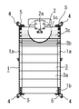
図1はこの発明の実施の形態1におけるエレベータの釣合い重り装置の正面図、図2はその側面図、図3はその要部正面図である。図1乃至図3において、エレベータの主索(図示せず)によりエレベータのかご(図示せず)と釣瓶式に懸吊され、昇降路内をこのかごとは逆方向に昇降する釣合い重り装置は、釣合い重り装置全体の重量を支持する釣合い重り枠1と、この釣合い重り枠1の上部に回動自在に設けられ、その外周面に無端状に形成された綱溝に前記主索が巻き掛けられた釣合い重り用吊車2と、釣合い重り枠1に支持されるとともに、釣合い重り装置全体の重量が所定の重量を有するように調整された釣合い重り3と、釣合い重り枠1の上下両端部に設けられ、釣合い重り装置の両側に互いに対向するように昇降路内に立設された一対の釣合い重り用ガイドレール(図示せず)に係合することにより、釣合い重り装置の水平方向の移動を制限してその昇降方向を案内するガイドシュー4とから構成されている。
1 is a front view of an elevator balancing weight device according to
上記釣合い重り枠1はその全体が略四角環状を呈しており、横断面が略コ字状を呈するように曲成されて、その開口部が互いに対向するように所定の間隔を有して両側に略垂直に配置された一対の縦枠1aと、各端部が上記各縦枠1a下端部のコ字状部内に配置されて各縦枠1aにボルトによって締結固定されることにより、各縦枠1aの下端部を連結する下枠1bと、各端部が上記縦枠1a上端部の一側及び他側にボルトによって締結固定されることにより、両縦枠1aを間に挟むように各縦枠1aの上端部を連結する一対の上枠1cとが備えられている。
The
この上枠1cには、各上枠1cの中央部に渡って円柱状を呈する支持軸2aが固定されており、この支持軸2aに、所定の直径を有する上記釣合い重り用吊車2が回動自在に設けられている。また、上記ガイドシュー4は、下枠1bの下側両端部及び上枠1cの上側両端部に取付金5を介して設けられている。このガイドシュー4は、横断面が略コ字状を呈しており、その開口部がそれぞれ外側を向くようにして配置されている。
A
また、上記釣合い重り3は、釣合い重り装置全体の重量がかごに定員の半分の乗客が乗車した状態でかご全体の重量とほぼ等しくなるように、その積載重量が調整されている。ここで、釣合い重り3は、下枠1b上に載置された所定の重量を有する複数の加減重り3aと、この加減重り3a上に載置され、加減重り3aよりも小さな重量を有して釣合い重り装置全体の重量を微調整する複数の第一調整重り3bと、この第一調整重り3b上に載置され、第一調整重り3bと同様に加減重り3aよりも小さな重量を有して釣合い重り装置全体の重量を微調整するとともに、上記釣合い重り用吊車2の回動に干渉しないように、この釣合い重り用吊車2と所定の間隙を有してその両側に配置された複数の第二調整重り3cとから構成されている。
The weight of the
上記加減重り3a及び第一調整重り3bは、その両端部に外側に突出する凸部が設けられ、一端部に設けられた凸部が一側の縦枠1aのコ字状部内に、また、他端部に設けられた凸部が他側の縦枠1aのコ字状部内に配置されるように、両縦枠1a間に渡って設けられている。また、加減重り3a及び第一調整重り3bは、釣合い重り用吊車2の下端部よりも下方に位置するように設けられており、釣合い重り用吊車2が回動した際に、釣合い重り用吊車2及びこの釣合い重り用吊車2に巻き掛けられた主索に干渉しないように配置されている。なお、第一釣合い重りは、上記加減重り3a及び第一調整重り3bにより構成される。
The adjusting
一方、釣合い重り用吊車2の両側に配置された上記第二調整重り3c(第二釣合い重り)は、一端部が各縦枠1aのコ字状部内に配置されるとともに、他端部は、釣合い重り用吊車2外周面の綱溝に巻き掛けられた主索と所定の僅かな間隙を有するように配置されている。なお、図4はこの発明の実施の形態1における第二調整重り3cの側面図を示すものである。図1乃至図4において、第二調整重り3cの他端部と釣合い重り用吊車2に巻き掛けられた主索との間に形成される間隙は、何れの高さにおいても略一定の幅となるように構成されている。即ち、第二調整重り3cは、その設置高さにより長さが異なり、その他端部が、釣合い重り用吊車2外周面の綱溝に巻き掛けられた主索に沿って階段状となるように、支持軸2aと略同高さ付近若しくはそれ以上の高さにまで載置されている。なお、各第二調整重り3cの一端部には貫通孔が形成されており、この貫通孔に通し軸が挿通されることにより第二調整重り3cの位置が固定されている。
On the other hand, the
かかる構成を有することにより、釣合い重り用吊車2外周面の綱溝に巻き掛けられた主索が何らかの原因により綱溝から外れそうになった場合でも、第二調整重り3cの他端部に接触することにより、主索が釣合い重り用吊車2の綱溝から外れてしまうことを防止することができる。即ち、第二調整重り3cは、釣合い重り用吊車2の外周面と所定の間隙を有して配置されることにより、釣合い重り用吊車2外周面の綱溝に巻き掛けられた主索の外れ止め機能を兼用している。なお、主索が第二調整重り3cの他端部に接触した際に主索を傷付けてしまうような事故を防止するため、第二調整重り3cの他端部には、釣合い重り用吊車2の外周面に近接する端部に、釣合い重り用吊車2の幅方向に渡って所定のR面取り加工が施されている。
By having such a configuration, even if the main rope wound around the rope groove on the outer peripheral surface of the
この発明の実施の形態1によれば、釣合い重り枠1内に載置される釣合い重り3の一部が釣合い重り用吊車2の両側に配置されているため、即ち、第二調整重り3cが釣合い重り用吊車2の下端部よりも上方に位置するように配置されているため、全ての釣合い重り3を釣合い重り用吊車2の下端部より下方に配置していた従来の釣合い重り装置と比較して、釣合い重り装置の高さを縮小することが可能となる。また、第二調整重り3cが釣合い重り用吊車2外周面の綱溝に巻き掛けられた主索の外れ止め機能を備えているため、従来別装置として設置していた外れ止め装置が不要となり、さらに釣合い重り装置の小型化が可能となる。
According to the first embodiment of the present invention, part of the
実施の形態2.
図5はこの発明の実施の形態2におけるエレベータの釣合い重り装置の要部正面図、図6は、この発明の実施の形態2における第二調整重りの側面図である。図5及び図6において、釣合い重り用吊車2の両側に配置された第二調整重り3d(第二釣合い重り)の他端部には、釣合い重り用吊車2の外周面に近接する端部に、釣合い重り用吊車2の幅方向に渡って所定のC面取り加工が施されている。かかる構成を有することにより、第二調整重り3dが、釣合い重り用吊車2外周面の綱溝に巻き掛けられた主索の外れ止め機能を兼用するとともに、主索が第二調整重り3dの他端部に接触した場合でも、主索を傷付けるような事故を確実に防止することが可能となる。なお、その他は実施の形態1と同様の構成及び効果を有する。
FIG. 5 is a front view of an essential part of an elevator balancing weight device according to
1 釣合い重り枠
1a 縦枠
1b 下枠
1c 上枠
2 釣合い重り用吊車
2a 支持軸
3 釣合い重り
3a 加減重り
3b 第一調整重り
3c、3d 第二調整重り
4 ガイドシュー
5 取付金
1
Claims (4)
Priority Applications (1)
| Application Number | Priority Date | Filing Date | Title |
|---|---|---|---|
| JP2005110843A JP2006290496A (en) | 2005-04-07 | 2005-04-07 | Balance weight device for elevator |
Applications Claiming Priority (1)
| Application Number | Priority Date | Filing Date | Title |
|---|---|---|---|
| JP2005110843A JP2006290496A (en) | 2005-04-07 | 2005-04-07 | Balance weight device for elevator |
Publications (1)
| Publication Number | Publication Date |
|---|---|
| JP2006290496A true JP2006290496A (en) | 2006-10-26 |
Family
ID=37411500
Family Applications (1)
| Application Number | Title | Priority Date | Filing Date |
|---|---|---|---|
| JP2005110843A Pending JP2006290496A (en) | 2005-04-07 | 2005-04-07 | Balance weight device for elevator |
Country Status (1)
| Country | Link |
|---|---|
| JP (1) | JP2006290496A (en) |
Cited By (4)
| Publication number | Priority date | Publication date | Assignee | Title |
|---|---|---|---|---|
| CN103708330A (en) * | 2013-12-17 | 2014-04-09 | 康力电梯股份有限公司 | Elevator counterweight device |
| CN104176608A (en) * | 2014-08-08 | 2014-12-03 | 康力电梯股份有限公司 | Elevator counterweight device |
| CN108349700A (en) * | 2016-11-25 | 2018-07-31 | 株式会社日立制作所 | The balance weight and lift appliance of lift appliance |
| WO2021070318A1 (en) * | 2019-10-10 | 2021-04-15 | 三菱電機株式会社 | Elevator counterweight device |
-
2005
- 2005-04-07 JP JP2005110843A patent/JP2006290496A/en active Pending
Cited By (6)
| Publication number | Priority date | Publication date | Assignee | Title |
|---|---|---|---|---|
| CN103708330A (en) * | 2013-12-17 | 2014-04-09 | 康力电梯股份有限公司 | Elevator counterweight device |
| CN104176608A (en) * | 2014-08-08 | 2014-12-03 | 康力电梯股份有限公司 | Elevator counterweight device |
| CN108349700A (en) * | 2016-11-25 | 2018-07-31 | 株式会社日立制作所 | The balance weight and lift appliance of lift appliance |
| WO2021070318A1 (en) * | 2019-10-10 | 2021-04-15 | 三菱電機株式会社 | Elevator counterweight device |
| JPWO2021070318A1 (en) * | 2019-10-10 | 2021-04-15 | ||
| JP7134366B2 (en) | 2019-10-10 | 2022-09-09 | 三菱電機株式会社 | elevator counterweight device |
Similar Documents
| Publication | Publication Date | Title |
|---|---|---|
| KR20060058148A (en) | Elevator device | |
| JP2011140374A (en) | Double-deck elevator | |
| JP2006290496A (en) | Balance weight device for elevator | |
| AU2004291360B2 (en) | Elevator suspension arrangement | |
| JP4677409B2 (en) | Elevator equipment | |
| JP6449485B2 (en) | Elevator equipment counterweight and elevator equipment | |
| JP4530857B2 (en) | Elevator system and its sheave assembly | |
| JP5517491B2 (en) | Elevator equipment | |
| WO2006064554A1 (en) | Hoist for elevator | |
| JP5320858B2 (en) | Elevator suspension equipment | |
| JP5079495B2 (en) | Elevator suspension equipment | |
| JP4901146B2 (en) | elevator | |
| JP5798613B2 (en) | Elevator counterweight device | |
| JP4658067B2 (en) | Elevator equipment | |
| JP2009155087A (en) | Elevator device | |
| CN107640680B (en) | Elevator vibration-proof device | |
| JP4946034B2 (en) | Compensation chain guide device for elevator | |
| JP2003221177A (en) | Hoisting machine device for elevator | |
| JP4974374B2 (en) | Installation method of elevator suspension rod vibration isolator | |
| JP4999949B2 (en) | Elevator system | |
| JP2005306513A (en) | Elevator device | |
| JPWO2005082767A1 (en) | Elevator equipment | |
| JP5368962B2 (en) | Elevator emergency stop device | |
| JP2005212941A (en) | Coupling device for main cables of elevator | |
| JP2009292561A (en) | Elevator device having no machine room |