以下、遊技機の一種であるパチンコ遊技機(以下、「パチンコ機」という)に適用した場合のいくつかの実施形態について説明する。
Hereinafter, some embodiments when applied to a pachinko gaming machine (hereinafter referred to as “pachinko machine”) which is a kind of gaming machine will be described.
(第1実施形態)
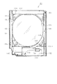
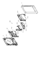
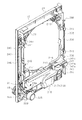
まず、第1実施形態について図面を用いて説明する。図1はパチンコ機10の正面図、図2はパチンコ機10の主要な構成を展開又は分解して示す斜視図、図3はパチンコ機10を構成する本体枠12の前面構成を示す正面図である。なお、図2、図3では便宜上、パチンコ機10の遊技領域内の構成を空白としている。
(First embodiment)
First, a first embodiment will be described with reference to the drawings. 1 is a front view of the pachinko machine 10, FIG. 2 is a perspective view showing an exploded or exploded main configuration of the pachinko machine 10, and FIG. 3 is a front view showing a front structure of a main body frame 12 constituting the pachinko machine 10. is there. In FIG. 2 and FIG. 3, the configuration in the game area of the pachinko machine 10 is left blank for convenience.
図1〜図3に示すように、パチンコ機10は、当該パチンコ機10の外殻を形成する外枠11を備えている。外枠11は、遊技ホールへの設置の際に、いわゆる島設備に取り付けられる。外枠11は、木製の板材を全体として矩形枠状に組み合わせた状態とされ、各板材を小ネジ等の離脱可能な締結部材により固定することによって構成されている。外枠11を合成樹脂やアルミニウム等の金属によって構成することも可能である。
As shown in FIGS. 1 to 3, the pachinko machine 10 includes an outer frame 11 that forms an outer shell of the pachinko machine 10. The outer frame 11 is attached to a so-called island facility when installed in the game hall. The outer frame 11 is in a state in which wooden plate materials are combined in a rectangular frame shape as a whole, and is configured by fixing each plate material with a detachable fastening member such as a small screw. The outer frame 11 can be made of a metal such as synthetic resin or aluminum.
外枠11の一側部には、本体枠12が開閉可能に支持されている。その開閉軸線はパチンコ機10の正面からみて左側に上下へ延びるように設定されており、その開閉軸線を軸心にして本体枠12が前方側に開放できるようになっている。本体枠12は合成樹脂、具体的にはABS樹脂により構成されている。ABS樹脂を用いることにより、比較的低コストで耐衝撃性の高い本体枠12を得ることができる。本体枠12をアルミニウム等の金属によって構成してもよい。なお本実施の形態では、外枠11と本体枠12とにより遊技機本体が構成されている。外枠11に代わる構成として設置枠体を遊技ホール側に予め設けておき、遊技ホールへのパチンコ機10の設置に際しては本体枠12を前記設置枠体に組み付ける構成とすることも可能である。
A body frame 12 is supported at one side of the outer frame 11 so as to be openable and closable. The opening / closing axis is set to extend vertically to the left as viewed from the front of the pachinko machine 10, and the main body frame 12 can be opened to the front side with the opening / closing axis as the axis. The main body frame 12 is made of synthetic resin, specifically ABS resin. By using the ABS resin, the main body frame 12 having a relatively low cost and high impact resistance can be obtained. The body frame 12 may be made of a metal such as aluminum. In the present embodiment, the outer frame 11 and the main body frame 12 constitute a gaming machine main body. As an alternative to the outer frame 11, an installation frame body may be provided in advance on the game hall side, and the main body frame 12 may be assembled to the installation frame body when the pachinko machine 10 is installed in the game hall.
本体枠12の前面側の下部位置には、前面板14が設けられている。前面板14は横長状に形成され、その横幅は本体枠12の横幅とほぼ一致するように構成されている。前面板14は、幅方向ほぼ中央部において手前側へ膨出した膨出部15aを有するベース部15と、ベース部15の膨出部15a内側に設けられ下方にくぼんだ皿形状をなす球受皿としての下皿16と、下皿16の奥側の壁面を構成する奥壁パネル17とを備えている。ベース部15は本体枠12に対してネジ等の締結部材により固定されていることから、ベース部15が本体枠12に対する取付部を構成している。ベース部15には膨出部15aよりも右方に、手前側へ突出するようにして遊技球発射ハンドル18が設けられている。奥壁パネル17には球排出口17aが設けられており、球排出口17aより排出された遊技球が下皿16内に貯留されるようになっている。
A front plate 14 is provided at a lower position on the front side of the main body frame 12. The front plate 14 is formed in a horizontally long shape, and the width thereof is configured to substantially coincide with the width of the main body frame 12. The front plate 14 includes a base portion 15 having a bulging portion 15a that bulges to the near side in a substantially central portion in the width direction, and a ball tray that is provided inside the bulging portion 15a of the base portion 15 and has a dish shape that is recessed downward. And a back wall panel 17 constituting a wall on the back side of the bottom plate 16. Since the base portion 15 is fixed to the main body frame 12 by a fastening member such as a screw, the base portion 15 constitutes an attachment portion for the main body frame 12. A game ball launching handle 18 is provided on the base portion 15 so as to protrude to the right side of the bulging portion 15a. The back wall panel 17 is provided with a ball discharge port 17 a, and the game balls discharged from the ball discharge port 17 a are stored in the lower plate 16.
ベース部15の膨出部15a前面側にはスライド式の球抜きレバー19が設けられている。なお、球抜きレバー19はプッシュ式としてもよい。そして、球抜きレバー19が操作されると下皿16の底面に設けられた図示しない閉鎖板が一体に又はリンクを介して移動して球抜き穴が開放され、下皿16内の貯留球が下方に排出されるよう構成されている。球抜きレバー19には球抜き穴を塞ぐ側へ球抜きレバー19を付勢するコイルバネ等の付勢部材が設けられ、球抜きレバー19の操作が解除された際には付勢部材の付勢力によって閉鎖板が球抜き穴の開放位置に復帰する構成となっている。奥壁パネル17の球排出口17aとは異なる位置には、多数の小孔が集合したスピーカカバー部17bが形成されており、当該パネル17の後方に設置されたスピーカ20の出力音がスピーカカバー部17bを通じて前方に発せられるようになっている。
A slide-type ball removal lever 19 is provided on the front side of the bulging portion 15 a of the base portion 15. The ball removal lever 19 may be a push type. When the ball removal lever 19 is operated, a closing plate (not shown) provided on the bottom surface of the lower plate 16 moves integrally or via a link to open the ball removal hole, and the stored balls in the lower plate 16 are moved. It is configured to be discharged downward. The ball removal lever 19 is provided with a biasing member such as a coil spring that biases the ball removal lever 19 toward the side where the ball removal hole is closed, and the biasing force of the biasing member when the operation of the ball removal lever 19 is released. Thus, the closing plate returns to the opening position of the ball hole. A speaker cover portion 17b in which a large number of small holes are gathered is formed at a position different from the ball discharge port 17a of the back wall panel 17, and the output sound of the speaker 20 installed behind the panel 17 is the speaker cover. It is emitted forward through the portion 17b.
ベース部15には膨出部15aの左方に灰皿21が設けられている。灰皿21は、内部に溜まった吸い殻等を除去しやすいように手前側下方に反転可能に取り付けられており、その右側面と背面とでベース部15に対面している。具体的な図示は省略するが、灰皿21の右側面には当該灰皿21を回動可能な状態で片持ち支持するための支軸が設けられ、同背面には灰皿21が図示のように上方に開口した位置でベース部15に係止される係止部が設けられている。前面板14はその大部分が本体枠12と同様、ABS樹脂にて成形されている。前面板14はパチンコ機10の前面側に露出されるが、ABS樹脂で成形していることによって、装飾等の目的で表面の適宜箇所にメッキを施すことが可能となる。なお、灰皿21が近くに配置されている関係上、下皿16と奥壁パネル17とを構成する部位に関しては難燃性のABS樹脂を用い、仮に誤ってたばこ等を置いても燃えにくくなるよう構成することが好ましい。
The base part 15 is provided with an ashtray 21 on the left side of the bulging part 15a. The ashtray 21 is attached so as to be able to be reversed to the lower side on the front side so as to easily remove the butts and the like accumulated in the inside, and faces the base portion 15 on the right side surface and the back surface thereof. Although a specific illustration is omitted, a support shaft for cantilevering the ashtray 21 in a rotatable state is provided on the right side surface of the ashtray 21, and the ashtray 21 is located upward on the back as shown in the figure. A locking portion that is locked to the base portion 15 is provided at a position that is open to the bottom. Most of the front plate 14 is formed of ABS resin in the same manner as the main body frame 12. The front plate 14 is exposed on the front side of the pachinko machine 10, but by molding it with ABS resin, it is possible to plate appropriate portions of the surface for the purpose of decoration or the like. In addition, since the ashtray 21 is disposed in the vicinity, the portion constituting the lower plate 16 and the back wall panel 17 is made of flame-retardant ABS resin, so that it is difficult to burn even if cigarettes are accidentally placed. It is preferable to configure as described above.
本体枠12の前面側の前面板14を除く範囲には、本体枠12を覆うようにして前面扉としての前扉枠13が設けられている。従って、前面板14と前扉枠13とにより本体枠12の前面側全体が覆われている。前扉枠13は、本体枠12に対して開閉可能に取り付けられており、本体枠12と同様、パチンコ機10の正面からみて左側に上下に延びる開閉軸線を軸心にして前方側に開放できるようになっている。なお、前扉枠13は前面板14と同様、ABS樹脂にて成形されている。前扉枠13はパチンコ機10の前面側に露出されるが、ABS樹脂で成形していることによって、装飾等の目的で表面の適宜箇所にメッキを施すことが可能となる。
A front door frame 13 as a front door is provided in a range excluding the front plate 14 on the front side of the main body frame 12 so as to cover the main body frame 12. Accordingly, the entire front side of the main body frame 12 is covered by the front plate 14 and the front door frame 13. The front door frame 13 is attached to the main body frame 12 so as to be openable and closable. Like the main body frame 12, the front door frame 13 can be opened forward with an opening / closing axis extending vertically to the left when viewed from the front of the pachinko machine 10. It is like that. The front door frame 13 is formed of ABS resin, like the front plate 14. The front door frame 13 is exposed on the front side of the pachinko machine 10, but by molding it with ABS resin, it is possible to plate appropriate portions of the surface for the purpose of decoration or the like.
前扉枠13の下部位置には、下皿16の上方において手前側へ膨出した膨出部22が設けられ、その膨出部22内側には上方に開口した上皿23が設けられている。上皿23は、後述する払出装置より払い出された遊技球を一旦貯留し、一列に整列させながら遊技球発射装置側へ導くための球受皿である。膨出部22前面側には上皿23用の球抜きレバー24が設けられており、この球抜きレバー24を操作すると上皿23の最下流部付近に設けられた球抜き通路(図示略)が開放され、上皿23内の貯留球が下皿16へ排出されるようになっている。なお、上皿23も下皿16等と同様、難燃性のABS樹脂にて構成することが可能である。
A lower portion of the front door frame 13 is provided with a bulging portion 22 that bulges to the near side above the lower plate 16, and an upper plate 23 that opens upward is provided inside the bulging portion 22. . The upper plate 23 is a ball receiving tray for temporarily storing game balls paid out from a payout device, which will be described later, and guiding them to the game ball launching device side while aligning them in a row. A ball removal lever 24 for the upper plate 23 is provided on the front surface side of the bulging portion 22, and when this ball removal lever 24 is operated, a ball removal passage (not shown) provided near the most downstream portion of the upper plate 23. Is opened, and the stored balls in the upper plate 23 are discharged to the lower plate 16. In addition, the upper plate 23 can also be comprised with a flame-retardant ABS resin similarly to the lower plate 16 grade | etc.,.
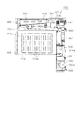
図3に示すように、本体枠12は、外形が前記外枠11とほぼ同一形状をなす樹脂ベース25を主体に構成されており、樹脂ベース25の中央部には略円形状の窓孔26が形成されている。樹脂ベース25の後側には遊技盤30が着脱可能に装着されている。図4に示すように、遊技盤30は略四角形状の合板よりなり、その周縁部が樹脂ベース25の裏側に当接した状態で取着されている。すなわち、遊技盤30はパチンコ機10後方より取り付けられ、遊技盤30の前面部の略中央部分だけが樹脂ベース25の窓孔26を通じて本体枠12の前面側に露出した状態となっている。
As shown in FIG. 3, the main body frame 12 is mainly composed of a resin base 25 whose outer shape is substantially the same as that of the outer frame 11, and a substantially circular window hole 26 is formed at the center of the resin base 25. Is formed. A game board 30 is detachably mounted on the rear side of the resin base 25. As shown in FIG. 4, the game board 30 is made of a substantially rectangular plywood, and is attached in a state where the peripheral edge thereof is in contact with the back side of the resin base 25. That is, the game board 30 is attached from the rear of the pachinko machine 10, and only the substantially central portion of the front part of the game board 30 is exposed to the front side of the main body frame 12 through the window hole 26 of the resin base 25.
次に、遊技盤30の構成を図4に基づいて説明する。遊技盤30には、ルータ加工が施されることによって前後方向に貫通する大小複数の開口部が形成されている。各開口部には一般入賞口31、可変入賞装置32、作動口33、スルーゲート34及び可変表示ユニット35等がそれぞれ設けられている。実際には、一般入賞口31、可変入賞装置32、作動口33、スルーゲート34及び可変表示ユニット35は木ねじ等により遊技盤表面に取り付けられている。本実施の形態では、可変表示ユニット35が遊技盤30の略中央に配置され、その下方に作動口33が配置され、さらにその下方に可変入賞装置32が配置されている。また、可変表示ユニット35の左右両側にスルーゲート34が配置され、遊技盤30の下部両側に一般入賞口31がそれぞれ複数配置されている。作動口33には、所定の条件下で作動状態(開放状態)となる電動役物が付随的に設けられている。前記一般入賞口31、可変入賞装置32及び作動口33に遊技球が入ると、それが後述する検出スイッチにより検出され、その検出結果に基づいて上皿23(場合によっては下皿16)に対し所定数の賞品球が払い出される。その他に、遊技盤30の最下部にはアウト口36が設けられており、各種入賞口等に入らなかった遊技球はアウト口36を通って図示しない球排出路の方へと案内されるようになっている。アウト口36は、遊技盤30の下端略中央を逆U字状に切り欠いて形成されている。そのため、アウト口を穴状に形成していた従来構成に比べ、アウト口形成が容易となる(但し、図4では手前側にレールユニット50が重ねて設けられているため、アウト口36が閉じた状態で示されている)。また、遊技盤30には、遊技球の落下方向を適宜分散、調整等するために多数の釘が植設されていると共に、風車37等の各種部材(役物)が配設されている。
Next, the structure of the game board 30 is demonstrated based on FIG. The game board 30 is formed with a plurality of large and small openings penetrating in the front-rear direction by being subjected to router processing. Each opening is provided with a general winning port 31, a variable winning device 32, an operating port 33, a through gate 34, a variable display unit 35, and the like. Actually, the general winning port 31, the variable winning device 32, the operating port 33, the through gate 34, and the variable display unit 35 are attached to the surface of the game board by wood screws or the like. In the present embodiment, the variable display unit 35 is disposed substantially at the center of the game board 30, the operation port 33 is disposed below the variable display unit 35, and the variable winning device 32 is disposed further below. In addition, through gates 34 are arranged on the left and right sides of the variable display unit 35, and a plurality of general winning holes 31 are arranged on both sides of the lower part of the game board 30. The operating port 33 is additionally provided with an electric accessory that is activated (opened) under a predetermined condition. When a game ball enters the general winning port 31, the variable winning device 32, and the operating port 33, it is detected by a detection switch which will be described later, and based on the detection result, the upper plate 23 (in some cases, the lower plate 16) is detected. A predetermined number of prize balls are paid out. In addition, an out port 36 is provided at the lowermost part of the game board 30 so that game balls that have not entered various winning ports etc. are guided through the out port 36 to a ball discharge path (not shown). It has become. The out port 36 is formed by cutting out the substantially lower center of the game board 30 in an inverted U shape. Therefore, compared to the conventional configuration in which the out port is formed in a hole shape, the out port can be formed more easily (however, in FIG. Is shown). The game board 30 is provided with a large number of nails for appropriately dispersing and adjusting the falling direction of the game balls, and various members (functions) such as a windmill 37 are disposed.
遊技盤30の左右両側部には、組付相手である本体枠12の左右両側からの張出領域との干渉を回避するように凹部としての切欠38が複数箇所に形成されている。
Notches 38 as recesses are formed at a plurality of locations on the left and right sides of the game board 30 so as to avoid interference with the protruding areas from the left and right sides of the body frame 12 that is the assembly partner.
可変表示ユニット35には、作動口33への入賞をトリガとして第1図柄(特別図柄)を変動表示する図柄表示装置41が設けられている。可変表示ユニット35には、図柄表示装置41を囲むようにしてセンターフレーム43が配設されている。このセンターフレーム43は、その上部がパチンコ機10前方に延出している。これにより、図柄表示装置41の表示画面の前方を遊技球が落下していくのが防止されており、遊技球の落下により表示画面の視認性が低下するといった不都合が生じない構成となっている。センターフレーム43の上部中央には、第1特定ランプ部47及び第2特定ランプ部48が横並びの状態で設けられている。また、これら両特定ランプ部47,48が配設された領域を挟むように、第1特定ランプ部47及び図柄表示装置41に対応した保留ランプ44が設けられている。遊技球が作動口33を通過した回数は最大4回まで保留され、保留ランプ44の点灯によってその保留個数が表示されるようになっている。なお、保留ランプ44は、図柄表示装置41の一部で変動表示される構成等であっても良い。上述したように、センターフレーム43の上部がパチンコ機10前方に延出していることにより、保留ランプ44、第1特定ランプ部47及び第2特定ランプ部48の視認性が遊技球の落下により阻害されない構成となっている。センターフレーム43の下部には、第2特定ランプ部48に対応した保留ランプ46が設けられている。遊技球がスルーゲート34を通過した回数は最大4回まで保留され、保留ランプ46の点灯によってその保留個数が表示されるようになっている。なお、保留ランプ46は、前記保留ランプ44と同様に、図柄表示装置41の一部で変動表示される構成等であっても良い。
The variable display unit 35 is provided with a symbol display device 41 for variably displaying the first symbol (special symbol) with a winning at the operation port 33 as a trigger. The variable display unit 35 is provided with a center frame 43 so as to surround the symbol display device 41. The center frame 43 has an upper portion extending forward of the pachinko machine 10. As a result, the game ball is prevented from dropping in front of the display screen of the symbol display device 41, and the inconvenience that the visibility of the display screen is lowered due to the fall of the game ball does not occur. . In the upper center of the center frame 43, a first specific lamp portion 47 and a second specific lamp portion 48 are provided side by side. Further, a holding lamp 44 corresponding to the first specific lamp unit 47 and the symbol display device 41 is provided so as to sandwich the area where both the specific lamp units 47 and 48 are disposed. The number of times that the game ball has passed through the operation port 33 is held up to 4 times, and the number of the hold is displayed by turning on the hold lamp 44. Note that the hold lamp 44 may be configured to be variably displayed on a part of the symbol display device 41. As described above, since the upper portion of the center frame 43 extends forward of the pachinko machine 10, the visibility of the holding lamp 44, the first specific lamp portion 47, and the second specific lamp portion 48 is hindered by the fall of the game ball. It is the composition which is not done. A holding lamp 46 corresponding to the second specific lamp portion 48 is provided below the center frame 43. The number of times that the game ball has passed through the through gate 34 is held up to a maximum of 4 times, and the holding number is displayed by turning on the holding lamp 46. Note that the hold lamp 46 may have a configuration in which the display is variably displayed in a part of the symbol display device 41, similarly to the hold lamp 44.
図柄表示装置41は8インチサイズの比較的大型の液晶ディスプレイを備えた液晶表示装置として構成されており、後述する表示制御装置により表示内容が制御される。図柄表示装置41には、例えば左、中及び右に並べて第1図柄が表示され、これらの図柄が上下方向にスクロールされるようにして変動表示されるようになっている。そして、予め設定されている有効ライン上に所定の図柄の組合せが停止表示された場合には、大当たり発生となると共にそれ以降の遊技状態が特別遊技状態としての大当たり状態に移行することとなる。この図柄の変動表示については、後に詳細に説明することとする。なお、図柄表示装置41は、8インチ以外の10インチ,7インチ等の液晶ディスプレイを備えたもの、ワイドサイズのディスプレイを備えたもの、又はCRT,ドットマトリックス,7セグメント等その他のタイプにより表示画面を構成したものであってもよい。
The symbol display device 41 is configured as a liquid crystal display device provided with a relatively large liquid crystal display of 8 inches, and the display content is controlled by a display control device described later. On the symbol display device 41, for example, the first symbols are displayed side by side on the left, middle, and right, and these symbols are variably displayed as they are scrolled up and down. When a predetermined symbol combination is stopped and displayed on a preset active line, a big win is generated and the subsequent gaming state is shifted to a big winning state as a special gaming state. This symbol variation display will be described in detail later. In addition, the symbol display device 41 has a display screen according to other types such as a CRT, a dot matrix, a 7-segment display, or the like provided with a liquid crystal display such as a 10-inch or 7-inch other than the 8-inch. It may be configured.
第1特定ランプ部47には、その内側に赤、緑、青の3色発光タイプのLEDランプが配設されている。そして、作動口33への入賞をトリガとして、所定の順序で発光色の切り替えが行われる。具体的には、作動口33への入賞をトリガとして、赤色光が点灯され、その状態で所定時間が経過すると緑色光に発光色が切り替えられる。そして、緑色光が点灯された状態で前記所定時間が経過すると青色光に発光色が切り替えられる。その後、発光色の切り替え停止時期がくるまで、赤色、緑色、青色という順序で発光色の切り替えが繰り返し行われる。これにより、第1特定ランプ部47には、赤色、緑色、青色が、この順序で繰り返し表示されることとなる。そして、最終的に赤色又は緑色が停止表示された場合には、大当たり発生となると共にそれ以降の遊技状態が大当たり状態に移行し、青色が停止表示された場合には、大当たり発生とならず大当たり状態に移行しない。また、本実施形態では、最終的に赤色で停止表示された場合と、最終的に緑色で停止表示された場合とで移行する大当たり状態が異なっており、後者の方がより遊技者に有利な大当たり状態に移行する。この発光色の切り替えに関しては、後に詳細に説明することとする。
The first specific lamp portion 47 is provided with a red, green, and blue three-color light emission type LED lamp. Then, the emission color is switched in a predetermined order using a winning at the operation port 33 as a trigger. Specifically, red light is turned on with a winning at the operation port 33 as a trigger, and the emission color is switched to green light when a predetermined time elapses in that state. Then, when the predetermined time elapses with the green light turned on, the emission color is switched to blue light. Thereafter, the emission color is repeatedly switched in the order of red, green, and blue until the emission color switching stop time comes. Accordingly, red, green, and blue are repeatedly displayed in this order on the first specific lamp unit 47. Finally, when red or green is stopped and displayed, the jackpot is generated and the subsequent gaming state shifts to the jackpot state. When blue is stopped and displayed, the jackpot is not generated and the jackpot is generated. Does not transition to the state. Further, in the present embodiment, the jackpot state to be transferred is different between the case where the stop is finally displayed in red and the case where the stop is finally displayed in green, and the latter is more advantageous to the player. Transition to jackpot state. The switching of the emission color will be described in detail later.
一方、第2特定ランプ部48には、その内側に赤、緑の2色発光タイプのLEDランプが配設されている。この第2特定ランプ部48は、スルーゲート34の通過をトリガとして、所定の順序で発光色の切り替えが行われる。具体的には、遊技球がスルーゲート34を通過すると、赤色光の点灯と緑色光の点灯とが交互に行われる。これにより、第2特定ランプ部48には、赤色、緑色が交互に表示されることとなる。そして、赤色が停止表示された場合には、作動口33に付随する電動役物が所定時間だけ開放状態となるよう構成されている。
On the other hand, the second specific lamp portion 48 is provided with red and green two-color light emitting type LED lamps inside. In the second specific lamp unit 48, the emission color is switched in a predetermined order with the passage of the through gate 34 as a trigger. Specifically, when the game ball passes through the through gate 34, lighting of red light and lighting of green light are alternately performed. Thus, red and green are alternately displayed on the second specific lamp unit 48. When the red color is stopped and displayed, the electric accessory attached to the operation port 33 is opened for a predetermined time.
可変入賞装置32は、通常は遊技球が入賞できない又は入賞し難い閉状態になっており、大当たり状態に移行すると遊技球が入賞しやすい所定の開放状態に切り換えられるようになっている。より詳しくは、大当たり状態に移行すると、可変入賞装置32が所定の開放状態となり、遊技球が入賞し易い状態となる。可変入賞装置32の開放態様としては、所定時間(例えば30秒間)の経過又は所定個数(例えば10個)の入賞を1ラウンドとして、可変入賞装置32内の継続入賞口への入賞を条件として次ラウンドへの移行条件成立とし、複数ラウンド(例えば16ラウンド)を上限として可変入賞装置32が繰り返し開放されるものが一般的である。
The variable winning device 32 is normally in a closed state in which a game ball cannot be won or difficult to win, and is switched to a predetermined open state in which the game ball is easy to win when it shifts to a big win state. More specifically, when shifting to the big hit state, the variable winning device 32 is in a predetermined open state, and the game ball is easily won. As an opening mode of the variable prize winning device 32, a predetermined time (for example, 30 seconds) or a predetermined number (for example, ten) of winnings is defined as one round, and the following is performed on condition that a winning is made to a continuous prize opening in the variable prize winning device 32. In general, the variable winning device 32 is repeatedly opened with a condition for transition to a round established, with a maximum of a plurality of rounds (for example, 16 rounds).
遊技盤30には、遊技球発射装置から発射された遊技球を遊技盤30上部へ案内するためのレール部材としてのレールユニット50が取り付けられており、遊技球発射ハンドル18の回動操作に伴い発射された遊技球はレールユニット50を通じて所定の遊技領域に案内されるようになっている。レールユニット50はリング状をなす樹脂成型品にて構成されており、より具体的には、摩擦抵抗を低減するべくフッ素配合のポリカーボネート樹脂が用いられている。レールユニット50は、内外二重に設けられた内レール部51と外レール部52とを有する。内レール部51は上方の約1/4ほどを除いて略円環状に形成され、外レール部52は内レール部51の上方開放領域を囲むようにかつ内レール51の左側部と並行するように略半円環状に形成されている。
The game board 30 is provided with a rail unit 50 as a rail member for guiding the game ball launched from the game ball launching device to the upper part of the game board 30. The launched game ball is guided to a predetermined game area through the rail unit 50. The rail unit 50 is composed of a ring-shaped resin molded product, and more specifically, a fluorine-containing polycarbonate resin is used to reduce frictional resistance. The rail unit 50 has an inner rail portion 51 and an outer rail portion 52 that are provided in an inner and outer double. The inner rail portion 51 is formed in a substantially annular shape except for about 1/4 of the upper portion, and the outer rail portion 52 surrounds the upper open area of the inner rail portion 51 and is parallel to the left side portion of the inner rail 51. Are formed in a substantially semi-annular shape.
内レール部51は、他の樹脂部分と一体成型され、遊技盤30の面上にほぼ垂直に起立して設けられている。また、外レール部52は、内レール部51と同様に他の樹脂部分と一体成型され、遊技盤30の面上にほぼ垂直に起立して設けられた支持部52aを有し、その支持部52aの内側面に、遊技球の飛翔をより滑らかなものとするための摺動プレート52bが取り付けられている。摺動プレート52bは、長尺状をなすステンレス製の金属帯よりなり、複数箇所で支持部52aに支持されている。かかる場合、内レール部51と外レール部52とにより誘導レールが構成され、これら各レール部51,52が所定間隔を隔てて対向する部分により球案内通路が形成されている。なお、内外のレール部51,52が対向する部位では、遊技盤30との当接部53により各レール部51,52が連結されており、球案内通路は手前側に開放した溝状に形成されている。
The inner rail portion 51 is integrally formed with other resin portions, and is provided upright substantially vertically on the surface of the game board 30. Further, the outer rail portion 52 has a support portion 52a that is integrally molded with other resin portions in the same manner as the inner rail portion 51, and is provided substantially upright on the surface of the game board 30. A sliding plate 52b is attached to the inner surface of 52a to make the flight of the game ball smoother. The sliding plate 52b is made of a long metal strip made of stainless steel, and is supported by the support portion 52a at a plurality of locations. In such a case, a guide rail is constituted by the inner rail portion 51 and the outer rail portion 52, and a ball guide passage is formed by a portion where these rail portions 51 and 52 face each other with a predetermined interval. In addition, in the site | part which the inner and outer rail parts 51 and 52 oppose, each rail part 51 and 52 is connected by the contact part 53 with the game board 30, and a ball | bowl guide path is formed in the groove shape open | released to the near side. Has been.
レールユニット50において、前記球案内通路より遊技球が飛び出す部位(図4の左上部)には戻り球防止部材54が取着され、該飛び出した遊技球の最大飛翔部分に対応する部位(図4の右上部)には返しゴム55が取着されている。戻り球防止部材54により、一旦球案内通路から遊技盤30の上部へと飛び出した遊技球が球案内通路内に戻ってしまうといった事態が防止される。また、所定以上の勢いで発射された遊技球は返しゴム55に当たり、遊技領域の中央寄りに跳ね返されるようになっている。
In the rail unit 50, a return ball prevention member 54 is attached to a portion (the upper left portion in FIG. 4) from which the game ball jumps out of the ball guide passage, and a portion corresponding to the maximum flight portion of the jumped game ball (FIG. 4). In the upper right part), a return rubber 55 is attached. The return ball prevention member 54 prevents a situation in which a game ball that has once jumped from the ball guide passage to the upper portion of the game board 30 returns to the ball guide passage. In addition, the game ball launched at a predetermined momentum or more hits the return rubber 55 and is rebounded toward the center of the game area.
レールユニット50の外周部には、外方へ張り出した円弧状のフランジ56が形成されている。フランジ56は、遊技盤30に対する取付面を構成する。レールユニット50が遊技盤30に取り付けられる際には、遊技盤30上にフランジ56が当接され、その状態で、当該フランジ56に形成された複数の透孔にネジ等が挿通されて遊技盤30に対するレールユニット50の締結がなされる。ここで、レールユニット50の上下及び左右の各端部は略直線状に形成されている。つまり、レールユニット50の上下及び左右の各端部においてはフランジ56が切り落とされ、パチンコ機10における有限の領域にてレール径の拡張、すなわち遊技盤30上の遊技領域の拡張が図られるようになっている。レールユニット50は、遊技盤30上の遊技領域の最大幅となる位置が遊技盤30の左右端位置に至るように配設されている。なお、レールユニット50の球案内通路に対応する部位のなかでも特に遊技球の受け入れ部位に関しては、当該レールユニット50を強固に取り付けて遊技球の飛びを安定させるべく、該当するフランジ56が他よりも多い箇所(本実施の形態では3カ所、他は2カ所)でネジ止めされている。
An arc-shaped flange 56 projecting outward is formed on the outer periphery of the rail unit 50. The flange 56 constitutes a mounting surface for the game board 30. When the rail unit 50 is attached to the game board 30, the flange 56 is brought into contact with the game board 30, and in this state, screws or the like are inserted into a plurality of through holes formed in the flange 56. The rail unit 50 is fastened to 30. Here, the upper and lower and left and right ends of the rail unit 50 are formed in a substantially linear shape. That is, the flanges 56 are cut off at the upper and lower and left and right ends of the rail unit 50 so that the rail diameter can be expanded in a finite area in the pachinko machine 10, that is, the game area on the game board 30 can be expanded. It has become. The rail unit 50 is disposed such that the position of the gaming area on the gaming board 30 that is the maximum width reaches the left and right end positions of the gaming board 30. Among the parts corresponding to the ball guide passages of the rail unit 50, particularly with respect to the game ball receiving part, the corresponding flange 56 is provided from others in order to firmly attach the rail unit 50 and stabilize the flight of the game ball. There are also many screws (three in this embodiment, two in the other).
内レール部51及び外レール部52間の球案内通路の入口には、同球案内通路の一部を閉鎖するようにして凸部57が形成されている。凸部57は、内レール部51の外周部から下方へ延びるように形成され、遊技領域まで至らず球案内通路内を逆流してくるファール球をファール球通路76(図3参照)に導く機能を有する。遊技盤30の右下隅部及び左下隅部は、証紙等のシールやプレートを貼着するためのスペース(図のSa,Sb)となっており、この貼着スペースを確保するために、フランジ56に切欠58a,58bが形成されている。証紙等のシールを遊技盤30に直接貼り付ける構成とすることで、証紙等の不正な貼り直し等が行いにくいものとなっている。
A convex portion 57 is formed at the entrance of the ball guide passage between the inner rail portion 51 and the outer rail portion 52 so as to close a part of the ball guide passage. The convex portion 57 is formed so as to extend downward from the outer peripheral portion of the inner rail portion 51, and has a function of guiding a foul ball that does not reach the game area and flows backward in the ball guide passage to the foul ball passage 76 (see FIG. 3). Have The lower right corner and the lower left corner of the game board 30 are spaces (Sa, Sb in the figure) for sticking seals and plates such as certificate stamps, and in order to secure this attachment space, the flange 56 Notches 58a and 58b are formed in the upper and lower portions. By adopting a configuration in which a sticker such as a stamp is directly pasted on the game board 30, it is difficult to improperly paste the stamp or the like.
遊技盤30においてレールユニット50よりも外方の左上部には、前後に貫通した中継端子孔59が設けられており、この中継端子孔59を通じて、遊技盤裏面に設置した中継端子板の接続コネクタ60がパチンコ機10前面側に露出されるようになっている。
In the game board 30, a relay terminal hole 59 penetrating in the front-rear direction is provided in the upper left portion outside the rail unit 50, and through this relay terminal hole 59, a connector for connecting a relay terminal plate installed on the back of the game board 60 is exposed to the front side of the pachinko machine 10.
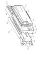
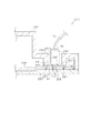
図3の説明に戻り、前記樹脂ベース25において、窓孔26(遊技盤30)の下方には、遊技球発射装置より発射された直後に遊技球を案内するための発射レール61が取り付けられている。発射レール61は、その後方の金属板62を介して樹脂ベース25に取付固定されており、所定の発射角度(打ち出し角度)にて直線的に延びるよう構成されている。従って、遊技球発射ハンドル18の回動操作に伴い発射された遊技球は、まずは発射レール61に沿って斜め上方に打ち出され、その後球案内通路を通じて遊技領域に案内される。ここで本実施の形態では、遊技球の発射位置を低くして発射レール61の傾斜角度(発射角度)を既存のものよりも幾分大きくし(すなわち発射レール61を立ち上げるようにし)、また発射レール61を遊技球発射装置の発射位置から遊技領域の中央位置(アウト口36)を越える位置まで延びるよう形成することで発射レール61の長さを既存のものよりも長くして十分な長さの球誘導距離を確保するようにしている。これにより、遊技球発射装置から発射された遊技球をより安定した状態で球案内通路に案内できるようにしている。さらに打出球の安定化を図るべく、発射レール61を設置した金属板62を大型化すると共に該金属板62を多数箇所(本実施の形態では15〜20カ所)でネジ止めしており、これにより発射レール61が遊技盤30に対して強固に位置決めされている。
Returning to the description of FIG. 3, in the resin base 25, below the window hole 26 (game board 30), a launch rail 61 for guiding the game ball immediately after being launched from the game ball launcher is attached. Yes. The firing rail 61 is fixedly attached to the resin base 25 via a metal plate 62 behind the firing rail 61, and is configured to extend linearly at a predetermined firing angle (launch angle). Accordingly, the game ball that is launched in accordance with the turning operation of the game ball launch handle 18 is first launched obliquely upward along the launch rail 61 and then guided to the game area through the ball guide path. Here, in the present embodiment, the launch position of the game ball is lowered so that the inclination angle (launch angle) of the launch rail 61 is somewhat larger than the existing one (that is, the launch rail 61 is raised), and By forming the launch rail 61 so as to extend from the launch position of the game ball launcher to a position beyond the center position (out port 36) of the game area, the launch rail 61 is made longer than the existing one and sufficiently long. The ball guide distance is secured. Thereby, the game ball launched from the game ball launching device can be guided to the ball guide passage in a more stable state. Further, in order to stabilize the launch ball, the metal plate 62 provided with the launch rail 61 is enlarged, and the metal plate 62 is screwed at a number of locations (15 to 20 in this embodiment). Thus, the launch rail 61 is firmly positioned with respect to the game board 30.
発射レール61と球案内通路との間には所定間隔の隙間があり、この隙間より下方にファール球通路76が設けられている。従って、仮に遊技球発射装置から発射された遊技球が戻り球防止部材54まで至らずファール球として球案内通路内を逆戻りする場合には、そのファール球がファール球通路76を介して下皿16に排出される。
There is a predetermined gap between the firing rail 61 and the ball guide passage, and a foul ball passage 76 is provided below the gap. Therefore, if the game ball launched from the game ball launching device does not reach the return ball prevention member 54 and returns as a foul ball in the ball guide passage, the foul ball passes through the foul ball passage 76 to the lower plate 16. To be discharged.
ファール球が球案内通路内を逆流してくる際、その多くは外レール部52に沿って流れ、外レール部52の下端部に到達した時点で下方に落下するが、一部のファール球は球案内通路内で暴れ、内レール部51側へ跳ね上がるものもある。この際、跳ね上がったファール球は、球案内通路入口の前記凸部57に当たり、ファール球通路76に誘導される。これにより、ファール球の全てがファール球通路76に確実に案内され、ファール球と次に発射される遊技球との干渉が抑制される。
When the foul balls flow backward in the ball guide passage, most of them flow along the outer rail portion 52 and fall downward when reaching the lower end portion of the outer rail portion 52. Some rampage in the ball guide passage and jump to the inner rail 51 side. At this time, the splashed foul ball hits the convex portion 57 at the entrance of the ball guide passage and is guided to the foul ball passage 76. Thereby, all of the foul balls are reliably guided to the foul ball passage 76, and interference between the foul balls and the game balls to be fired next is suppressed.
なお、詳しい図面の開示は省略するが、遊技球発射装置には、前扉枠13側の球出口(上皿23の最下流部より通じる球出口)から遊技球が1つずつ供給される。この際、本実施の形態では遊技球の発射位置を低くしたため、前扉枠13側の球出口から前記発射位置への落差が大きくなるが、発射レール61の発射基端部付近にはその右側と手前側にそれぞれガイド部材63,64を設置してある。これにより、前扉枠13側の球出口から供給される遊技球が常に所定の発射位置にセットされ、安定した発射動作が実現できる。また、遊技球発射装置には、基端部を中心に回動可能に支持された打球槌が設けられ、打球槌の回動に伴い遊技球が発射されるが、打球槌に関して軽量化が望まれている。それ故、アルミニウム等の軽金属への材料変更や槌シャフト部寸法の縮小化により打球槌の軽量化を図る一方で、十分な発射力を確保すべく、打球槌のヘッド部(基端部と反対側の先端部)に重り部を設けている。これにより、十分でかつ安定した遊技球の発射が実現できる。打球槌の重り部を上方に突出して設けることにより、打球槌を容易に摘んだりひっかけたりすることができ、槌先の打球強さの調整等がし易くなるという効果も得られる。
Although detailed disclosure of the drawings is omitted, one game ball is supplied to the game ball launching device one by one from the ball outlet on the front door frame 13 side (ball outlet leading from the most downstream portion of the upper plate 23). At this time, since the launch position of the game ball is lowered in this embodiment, the drop from the exit of the ball on the front door frame 13 side to the launch position becomes large, Guide members 63 and 64 are installed on the front side. Thereby, the game ball supplied from the ball exit on the front door frame 13 side is always set at a predetermined launch position, and a stable launch operation can be realized. In addition, the game ball launching device is provided with a ball striking rod that is supported so as to be rotatable about the base end portion, and a game ball is launched along with the rotation of the ball striking ball. It is rare. Therefore, while aiming to reduce the weight of the hitting ball by changing the material to a light metal such as aluminum and reducing the size of the hitting shaft, the head portion of the hitting ball (opposite to the base end) is required to ensure sufficient firing force. A weight is provided at the tip of the side. Thereby, sufficient and stable launch of the game ball can be realized. By providing the weight portion of the hitting ball projecting upward, the hitting ball can be easily picked or caught, and the effect of facilitating adjustment of the hitting strength of the hitting tip can be obtained.
また、本体枠12の前面において発射レール61の左側には、左右一対の排出口66,67が形成されると共に、その前方に、排出口66,67より排出された遊技球を上皿23又は下皿16の何れかに案内するための遊技球案内ユニット70が取り付けられている。便宜上以下の説明では、排出口66を第1排出口、排出口67を第2排出口ともいう。これら排出口66,67は、本体枠12の背面に設けられた遊技球分配部245(図10参照)に通じており、基本的に第1排出口66より遊技球の排出が行われ、この第1排出口66も含め上皿23に通じる通路が遊技球で一杯になると、第1排出口66に代えて第2排出口67より遊技球の排出が行われるようになっている。
A pair of left and right discharge ports 66, 67 are formed on the left side of the launch rail 61 on the front surface of the main body frame 12, and the game balls discharged from the discharge ports 66, 67 are placed in front of the upper plate 23 or A game ball guide unit 70 for guiding one of the lower dishes 16 is attached. For convenience, in the following description, the discharge port 66 is also referred to as a first discharge port, and the discharge port 67 is also referred to as a second discharge port. These discharge ports 66 and 67 communicate with a game ball distribution unit 245 (see FIG. 10) provided on the back surface of the main body frame 12, and game balls are basically discharged from the first discharge port 66. When the passage leading to the upper plate 23 including the first outlet 66 is filled with game balls, the game balls are discharged from the second outlet 67 instead of the first outlet 66.
遊技球案内ユニット70は、ポリカーボネート樹脂等の透明な樹脂材料により内部を視認可能に構成され、本体枠12に対して前扉枠13を閉鎖した状態で本体枠12と前扉枠13との間に収まるよう厚みが比較的薄くなるように形成されている。遊技球案内ユニット70には、前述のファール球通路76が一体的に形成されている。遊技球案内ユニット70には、前記排出口66,67と下皿16とを連通するための球排出通路71が形成されている。遊技球案内ユニット70には、本体枠12の第1排出口66の手前側に、上皿23に連通する連通口72が形成され、連通口72を閉鎖するようにして開閉プレート73が取り付けられている。開閉プレート73は支軸74により回動可能に支持され、付勢手段としてのバネ75により連通口72を閉鎖する位置に常時付勢されている。
The game ball guide unit 70 is configured to be visible with a transparent resin material such as polycarbonate resin, and between the main body frame 12 and the front door frame 13 with the front door frame 13 closed with respect to the main body frame 12. It is formed so that the thickness is comparatively thin so that it can be accommodated. The game ball guide unit 70 is integrally formed with the foul ball passage 76 described above. The game ball guide unit 70 is formed with a ball discharge passage 71 for communicating the discharge ports 66 and 67 with the lower plate 16. In the game ball guide unit 70, a communication port 72 communicating with the upper plate 23 is formed on the front side of the first discharge port 66 of the main body frame 12, and an opening / closing plate 73 is attached so as to close the communication port 72. ing. The opening / closing plate 73 is rotatably supported by a support shaft 74 and is always urged to a position where the communication port 72 is closed by a spring 75 as urging means.
遊技球案内ユニット70の上記構成によれば、前扉枠13を開放した状態ではバネ75の付勢力により開閉プレート73が図示の如く起き上がり、連通口72を閉鎖する。この状態では、第1排出口66より排出される遊技球が球排出通路71を通じて下皿16に案内される。従って、連通口72の上流側に遊技球が貯留されている状態で前扉枠13を開放した場合、その貯留球は連通口72よりこぼれ落ちることなく、球排出通路71を通じて下皿16に流下する。つまり、前飾り枠が省略され前扉枠13に対して上皿23が直接設けられる構成とした本パチンコ機10にあっても、前扉枠13の開放に際し連通口72の上流側にある遊技球がこぼれ落ちてしまうといった不都合が防止できる。これに対し、前扉枠13を閉鎖した状態では、前扉枠13の裏面に設けられた球通路樋138(図2参照)によりバネ75の付勢力に抗して開閉プレート73が押し開けられる。この状態では、第1排出口66より排出される遊技球が連通口72を介して上皿23に案内される。従って、連通口72より上流側の遊技球は上皿23に払い出される。なお、遊技球案内ユニット70の球排出通路71下流側には、下皿16に排出された遊技球が一杯(満タン)になったことを検知する下皿満タンスイッチが取り付けられている。
According to the above configuration of the game ball guide unit 70, the open / close plate 73 rises as shown in the figure by the urging force of the spring 75 when the front door frame 13 is opened, and the communication port 72 is closed. In this state, the game ball discharged from the first discharge port 66 is guided to the lower plate 16 through the ball discharge passage 71. Therefore, when the front door frame 13 is opened in a state where game balls are stored upstream of the communication port 72, the stored balls flow down to the lower plate 16 through the ball discharge passage 71 without spilling from the communication port 72. To do. In other words, even in the present pachinko machine 10 in which the front decorative frame is omitted and the upper plate 23 is directly provided on the front door frame 13, the game on the upstream side of the communication port 72 when the front door frame 13 is opened. The inconvenience of spilling a ball can be prevented. On the other hand, when the front door frame 13 is closed, the opening / closing plate 73 is pushed open against the biasing force of the spring 75 by a ball passage rod 138 (see FIG. 2) provided on the back surface of the front door frame 13. . In this state, the game ball discharged from the first discharge port 66 is guided to the upper plate 23 through the communication port 72. Accordingly, the game ball upstream of the communication port 72 is paid out to the upper plate 23. A lower plate full tank switch for detecting that the game ball discharged to the lower plate 16 is full (full tank) is attached to the downstream side of the ball discharge passage 71 of the game ball guide unit 70.
樹脂ベース25には、窓孔26の右下部に略四角形状の小窓78が設けられている。従って、遊技盤30の右下隅部スペース(図4のSa)に貼られた証紙等は、この小窓78を通じて視認できるようになっている。この小窓78から遊技盤30上に証紙等を直接貼り付けることも可能である。
The resin base 25 is provided with a substantially rectangular small window 78 at the lower right portion of the window hole 26. Accordingly, the stamp or the like attached to the lower right corner space (Sa in FIG. 4) of the game board 30 can be viewed through the small window 78. It is also possible to directly paste a stamp or the like on the game board 30 from the small window 78.
樹脂ベース25には、窓孔26の左上部にも小窓79が設けられている。この小窓79は、図4で説明した遊技盤30の中継端子孔59に対応する位置にそれとほぼ同一の形状で設けられ、中継端子孔59及び小窓79を通じて、遊技盤裏面に設置した中継端子板の接続コネクタ60が本体枠12の前面側に露出される。かかる構成において、前扉枠13側に設けた各種ランプに対しては、本体枠12(樹脂ベース25)の小窓79より露出した接続コネクタ60を介して電気的な接続がなされている。樹脂ベース25の上部には、前扉枠13の開放の状態を検出するための前扉枠開放スイッチ27が設けられている。前扉枠開放スイッチ27は、樹脂ベース25の前面に出没可能なピンを有しており、本体枠12に対して前扉枠13を閉じた状態ではピンが押し込まれて前扉枠13の閉鎖が検知され、本体枠12に対して前扉枠13を開いた状態ではピンが突出位置に戻って前扉枠13の開放が検知されるようになっている。樹脂ベース25の左右2カ所には、本体枠12に対して前扉枠13を閉じた際に前扉枠13背面の金具類(図5に示す補強板131〜134)に接触し、且つその金具類を本体枠12側に導通させてアース(接地)するための金属片28a,28bが取り付けられている。従って、金属片28a,28bを通じて、前扉枠13背面の金具類が本体枠12側の施錠装置やヒンジ金具に導通され、これら施錠装置やヒンジ金具と共にアースされる。
A small window 79 is also provided in the resin base 25 at the upper left portion of the window hole 26. The small window 79 is provided in the position corresponding to the relay terminal hole 59 of the game board 30 described in FIG. 4 in substantially the same shape as that. The connection connector 60 of the terminal board is exposed on the front side of the main body frame 12. In such a configuration, various lamps provided on the front door frame 13 side are electrically connected via the connection connector 60 exposed from the small window 79 of the main body frame 12 (resin base 25). A front door frame opening switch 27 for detecting the open state of the front door frame 13 is provided on the top of the resin base 25. The front door frame opening switch 27 has a pin that can be projected and retracted on the front surface of the resin base 25. When the front door frame 13 is opened with respect to the main body frame 12, the pin returns to the protruding position and the opening of the front door frame 13 is detected. When the front door frame 13 is closed with respect to the main body frame 12, the resin base 25 comes into contact with metal fittings (reinforcing plates 131 to 134 shown in FIG. 5) on the back of the front door frame 13, and Metal pieces 28a and 28b are attached to connect the metal fittings to the main body frame 12 side for grounding. Therefore, the metal fittings on the back of the front door frame 13 are conducted to the locking device and the hinge fitting on the main body frame 12 side through the metal pieces 28a and 28b, and are grounded together with the locking device and the hinge fitting.
本体枠12の左端側(開閉軸線側)には、前扉枠13を開閉可能に支持するための支持機構として、上下一対の支持金具81,82が取り付けられている。上側の支持金具81には手前側に切欠を有する支持孔83が設けられ、下側の支持金具82には上方へ突出する突起軸84が設けられている。なお、支持金具81,82に支持される前扉枠13の具体的構成については後述する。また、本体枠12の右端側(開閉軸線とは反対側)には、前扉枠13裏面側の開放端側に設けた上下一対の鉤金具155,156(図2参照)を挿入するための挿入孔87,88がそれぞれ設けられている。本パチンコ機10では、本体枠12や前扉枠13を施錠状態とするための施錠装置が本体枠12の裏面側に隠れて配置される構成となっている。従って、鉤金具155,156が挿入孔87,88を介して施錠装置に係止されることによって、前扉枠13が本体枠12に対して開放不能に施錠される。
A pair of upper and lower support brackets 81 and 82 are attached to the left end side (opening / closing axis line side) of the main body frame 12 as a support mechanism for supporting the front door frame 13 so that it can be opened and closed. The upper support fitting 81 is provided with a support hole 83 having a notch on the front side, and the lower support fitting 82 is provided with a protruding shaft 84 protruding upward. The specific configuration of the front door frame 13 supported by the support fittings 81 and 82 will be described later. Further, a pair of upper and lower metal fittings 155 and 156 (see FIG. 2) provided on the open end side on the back side of the front door frame 13 is inserted into the right end side (the side opposite to the opening / closing axis) of the main body frame 12. Insertion holes 87 and 88 are provided, respectively. The pachinko machine 10 is configured such that a locking device for locking the main body frame 12 and the front door frame 13 is hidden behind the main body frame 12. Therefore, the front door frame 13 is locked to the main body frame 12 so that it cannot be opened by locking the metal fittings 155 and 156 to the locking device via the insertion holes 87 and 88.
本体枠12の右下隅部には、外枠11に対する本体枠12の施錠及び解錠、並びに本体枠12に対する前扉枠13の施錠及び解錠を行うための鍵部材としてのシリンダ錠91が設置されている。シリンダ錠91は施錠装置に一体化されており、施錠装置のうちシリンダ錠91だけが本体枠12の前方に突出した状態で設けられている。この場合、シリンダ錠91は、遊技領域の最大幅となる位置とは異なる位置に設けられている。シリンダ錠91は、本体枠12の施解錠と前扉枠13の施解錠とを共に賄う機能を有しており、鍵穴に差し込んだキーを左(反時計回り方向)に回すと本体枠12の施錠が解かれ、逆にキーを右(時計回り方向)に回すと前扉枠13の施錠が解かれるようになっている。
A cylinder lock 91 as a key member for locking and unlocking the main body frame 12 with respect to the outer frame 11 and locking and unlocking the front door frame 13 with respect to the main body frame 12 is installed at the lower right corner of the main body frame 12. Has been. The cylinder lock 91 is integrated with the locking device, and only the cylinder lock 91 of the locking device is provided in a state of protruding in front of the main body frame 12. In this case, the cylinder lock 91 is provided at a position different from the position that is the maximum width of the game area. The cylinder lock 91 has a function to cover both the locking and unlocking of the main body frame 12 and the locking and unlocking of the front door frame 13, and when the key inserted into the key hole is turned counterclockwise (counterclockwise direction) When the key is unlocked and the key is turned to the right (clockwise direction), the front door frame 13 is unlocked.
図2に示すように、本体枠12には、シリンダ錠91を囲むようにして縦長状のカバー部材92が取り付けられている。詳細な図示は省略するが、カバー部材92には、その上端部及び下端部に係止部(フック)が形成されている。従って、上側の係止部を本体枠12側に係止させると共に、下側の係止部を本体枠12と前面板14との間に挟み込むことにより、カバー部材92が本体枠12に取り付けられる。前扉枠13には、カバー部材92の形状に合わせて切欠部145が形成されており、前扉枠13を閉鎖した状態ではこの前扉枠13と共にカバー部材92がパチンコ機前面部を構成する。なお、前扉枠13を閉鎖したとき、カバー部材92に形成された鍔部が前扉枠13により押さえられ、カバー部材92のがたつきが防止されるようになっている。
As shown in FIG. 2, a vertically long cover member 92 is attached to the main body frame 12 so as to surround the cylinder lock 91. Although detailed illustration is omitted, the cover member 92 has locking portions (hooks) formed at the upper end portion and the lower end portion thereof. Therefore, the cover member 92 is attached to the main body frame 12 by locking the upper locking portion to the main body frame 12 side and sandwiching the lower locking portion between the main body frame 12 and the front plate 14. . The front door frame 13 is formed with a notch 145 corresponding to the shape of the cover member 92. When the front door frame 13 is closed, the cover member 92 together with the front door frame 13 constitutes the front portion of the pachinko machine. . When the front door frame 13 is closed, the flange formed on the cover member 92 is pressed by the front door frame 13 to prevent the cover member 92 from rattling.
次に、前扉枠13について図1,図5を参照しつつ説明する。なお、図5は、前扉枠13の背面図である。
Next, the front door frame 13 will be described with reference to FIGS. FIG. 5 is a rear view of the front door frame 13.
前扉枠13には遊技領域のほぼ全域を前方から視認することができるようにした視認窓としての窓部101が形成されている。窓部101は、円形に近い略楕円形状をなし、より詳しくは、その左右側の略中央部が上下側に比べて緩やかに湾曲した形状となっている。なお、前記略中央部が直線状になる形状であってもよい。
The front door frame 13 is formed with a window portion 101 as a viewing window so that almost the entire game area can be viewed from the front. The window portion 101 has a substantially oval shape that is nearly circular, and more specifically, a substantially central portion on the left and right sides of the window portion 101 is gently curved as compared to the upper and lower sides. The substantially central portion may have a linear shape.
前扉枠13の下端部における左右両側には、本体枠12表面や遊技盤30表面等(証紙等を含む)の一部を視認できるよう透明樹脂を取り付けた小窓107が設けられている。小窓107に取り付けられる透明樹脂は、その内部の証紙等を工場等で容易に機械読み取りできるよう平坦状に構成される。但し、小窓107に、内部の証紙等をホール作業者等が容易に目視できるよう拡大レンズ部を設けることも可能である。
Small windows 107 to which a transparent resin is attached are provided on both the left and right sides of the lower end portion of the front door frame 13 so that a part of the surface of the main body frame 12 and the surface of the game board 30 (including certificate paper) can be visually recognized. The transparent resin attached to the small window 107 is formed in a flat shape so that the internal certificate paper or the like can be easily machine-read in a factory or the like. However, the small window 107 can be provided with a magnifying lens portion so that the hall operator or the like can easily see the internal certificate paper or the like.
前扉枠13にはその周囲(例えばコーナー部分)に各種ランプ等の発光手段が設けられている。これら発光手段は、大当たり状態下や所定のリーチ演出時等において点灯、点滅のように発光態様が変更制御されることにより、遊技中の演出効果を高める役割を果たす。例えば、窓部101の周縁に沿ってLED等の発光手段を内蔵した環状電飾部102が左右対称に設けられ、環状電飾部102の中央であってパチンコ機10の最上部にはLED等の発光手段を内蔵した中央電飾部103が設けられている。本パチンコ機10では、中央電飾部103が大当たりランプとして機能し、大当たり状態下で点灯や点滅を行うことにより大当たり状態に移行していることを報知する。また、上皿23周りにも、同じくLED等の発光手段を内蔵した上皿電飾部104が設けられている。その他、中央電飾部103の左右側方には、賞球払出中に点灯する賞球ランプ105と所定のエラー時に点灯するエラー表示ランプ106とがそれぞれ設けられている。なお、環状電飾部102は、内外二重の樹脂カバー層とその内側に収容された発射板付き発光体(LED)とよりなり、樹脂カバー層の各々の内側面には各層で縦横に交差する向きに突条(又は波状の突起)が設けられている。外側の樹脂カバー層は透明であり、内側の樹脂カバー層は有色である。従って、環状電飾部102を発光させれば、多数に分散化された状態、又は立体感を伴った状態の電飾が実現できるようになる。樹脂カバー層には、ガラス粉末入りの樹脂材料を用いると良い。このような樹脂カバー層の構成は、他の電飾部(例えば中央電飾部103や賞球ランプ105)に適用することもできる。
The front door frame 13 is provided with light emitting means such as various lamps around the periphery (for example, a corner portion). These light emitting means play a role of enhancing the effect of the game during the game by changing and controlling the light emission mode such as lighting and blinking in a big hit state or at a predetermined reach performance. For example, an annular illumination part 102 incorporating light emitting means such as LEDs is provided symmetrically along the periphery of the window part 101, and an LED or the like is provided at the center of the annular illumination part 102 and at the top of the pachinko machine 10. There is provided a central illumination unit 103 incorporating the light emitting means. In the pachinko machine 10, the central lighting unit 103 functions as a jackpot lamp, and notifies that the jackpot state has been reached by turning on or blinking under the jackpot state. Further, around the upper plate 23, there is also provided an upper plate illumination unit 104 that also incorporates light emitting means such as LEDs. In addition, on the left and right sides of the central illumination unit 103, there are respectively provided a prize ball lamp 105 that is lit during award ball payout and an error display lamp 106 that is lit when a predetermined error occurs. The annular illumination part 102 includes an inner and outer double resin cover layer and a light emitting body (LED) with a launch plate accommodated inside the resin cover layer. The inner surface of each resin cover layer intersects with each layer vertically and horizontally. A protrusion (or a wavy protrusion) is provided in the direction to be turned. The outer resin cover layer is transparent, and the inner resin cover layer is colored. Therefore, if the annular illumination part 102 is caused to emit light, it is possible to realize the illumination in a state of being dispersed in a large number or in a state accompanied with a stereoscopic effect. A resin material containing glass powder may be used for the resin cover layer. Such a configuration of the resin cover layer can also be applied to other electric decoration parts (for example, the central electric decoration part 103 and the prize ball lamp 105).
前扉枠13には、窓部101の下方位置に、貸球操作部120が配設されている。貸球操作部120には球貸しボタン121と、返却ボタン122と、度数表示部123とが設けられている。パチンコ機10の側方に配置されたカードユニット(球貸しユニット)に紙幣やカード等を投入した状態で、貸球操作部120によって球貸し操作、カード返却操作及びカード度数の確認を行うことができる。すなわち、球貸しボタン121は、カード等(記録媒体)に記録された情報に基づいて貸出球を得るために操作されるものであり、カード等に残額が存在する限りにおいて貸出球が払い出される。返却ボタン122は、カードユニットに挿入されたカード等の返却を求める際に操作される。度数表示部123はカード等の残額情報を表示するものである。なお、カードユニットを介さずに球貸し装置等から上皿に遊技球が直接貸し出されるパチンコ機(いわゆる現金機)では貸球操作部120が不要となるが、かかる場合には、貸球操作部120の設置部分に飾りシール等が付されるようになっている。これにより、貸球操作部120を設けた本パチンコ機10の構成において、カードユニットを用いたパチンコ機(いわゆるCR機)と現金機との共用が可能となる。
The front door frame 13 is provided with a ball rental operation portion 120 at a position below the window portion 101. The ball lending operation unit 120 is provided with a ball lending button 121, a return button 122, and a frequency display unit 123. A ball lending operation, a card return operation, and a card frequency check can be performed by the lending operation unit 120 in a state where a bill or a card is inserted into a card unit (a ball lending unit) arranged on the side of the pachinko machine 10. it can. That is, the ball lending button 121 is operated to obtain a lending ball based on information recorded on a card or the like (recording medium), and the lending ball is paid out as long as the remaining amount exists on the card or the like. The return button 122 is operated when requesting the return of a card or the like inserted into the card unit. The frequency display unit 123 displays remaining amount information such as a card. In a pachinko machine (so-called cash machine) in which game balls are rented directly from a ball lending device or the like to a top plate without using a card unit, the ball lending operation unit 120 is unnecessary. A decorative sticker or the like is attached to 120 installation portions. Thereby, in the configuration of the present pachinko machine 10 provided with the lending operation unit 120, the pachinko machine using a card unit (so-called CR machine) and the cash machine can be shared.
前扉枠13の裏側には、窓部101を囲むようにして金属製の各種補強部材が設けられている。詳しくは、図5に示すように、前扉枠13の裏側にあって窓部101の左右及び上下の外側にはそれぞれ補強板131,132,133,134が取り付けられている。これら補強板131〜134は相互に接触して連結されているが、図の左側及び上側の補強板132,133の連結部には直接の接触を避けるための樹脂パーツ135が介在されている。これにより、補強板131〜134による電気経路の閉じたループが切断され、ノイズの原因となる磁界の発生等が防止されている。
On the back side of the front door frame 13, various metal reinforcing members are provided so as to surround the window portion 101. Specifically, as shown in FIG. 5, reinforcement plates 131, 132, 133, and 134 are respectively attached to the back side of the front door frame 13 and on the left and right and upper and lower outer sides of the window portion 101. These reinforcing plates 131 to 134 are connected in contact with each other, but resin parts 135 for avoiding direct contact are interposed at the connecting portions of the left and upper reinforcing plates 132 and 133 in the drawing. Thereby, the closed loop of the electric path by the reinforcing plates 131 to 134 is cut, and the generation of a magnetic field causing noise is prevented.
図5の右側となる開閉軸線側の補強板131にはその上端部及び下端部に、本体枠12に対する組付機構として、組付金具151,152が取り付けられている。そして、本体枠12側の支持金具81,82(図3参照)に対して前扉枠13側の組付金具151,152が取り付けられている。すなわち、下側の組付金具152には下面に開口する軸穴が形成されており、その軸穴に下側の支持金具82の突起軸84が挿入される一方、上側の組付金具151の軸部が上側の支持金具81の支持孔83に挿入されることにより、本体枠12に対して前扉枠13が開閉可能に支持されている。また、同補強板131にはその中間位置にフック状をなす係合爪131aが設けられており、この係合爪131aは、前扉枠13を閉じた状態で本体枠12の孔部12a(図3参照)に挿入されるように構成されている。これにより、上皿23を含む形態で前扉枠13を構成し、その上下の軸支間隔を長くした本パチンコ機10においても、中間位置における前扉枠13の浮き上がりが防止できる。それ故、前扉枠13を浮かしての不正行為等が抑制されるようになっている。
Assembling mechanisms for the main body frame 12 are attached to the upper and lower ends of the opening / closing axis side reinforcing plate 131 on the right side of FIG. And the assembly | attachment metal fittings 151 and 152 by the side of the front door frame 13 are attached with respect to the support metal fittings 81 and 82 (refer FIG. 3) by the side of the main body frame 12. FIG. That is, a shaft hole that opens to the lower surface is formed in the lower mounting bracket 152, and the protruding shaft 84 of the lower support bracket 82 is inserted into the shaft hole, while the upper mounting bracket 151 By inserting the shaft portion into the support hole 83 of the upper support fitting 81, the front door frame 13 is supported to be openable and closable with respect to the main body frame 12. Further, the reinforcing plate 131 is provided with an engaging claw 131a having a hook shape at an intermediate position thereof, and the engaging claw 131a is formed in the hole 12a ( (See FIG. 3). Accordingly, even in the pachinko machine 10 in which the front door frame 13 is configured in a form including the upper plate 23 and the upper and lower shaft support intervals are increased, the front door frame 13 can be prevented from being lifted at the intermediate position. Therefore, an illegal act or the like floating the front door frame 13 is suppressed.
図5の左側となる開閉軸線とは反対側の補強板132には鉤形状をなす上下一対の鉤金具155,156が取り付けられている。これら鉤金具155,156は、後方に延び、本体枠12に設けた挿入孔87,88(図3参照)に対応するようにして設けられている。本体枠12に対して前扉枠13を閉鎖した際、鉤金具155,156が本体枠12側の挿入孔87,88に挿入されて施錠装置により施錠状態とされるようになっている。
A pair of upper and lower hook metal fittings 155 and 156 having a hook shape are attached to the reinforcing plate 132 on the opposite side to the open / close axis on the left side of FIG. These metal fittings 155 and 156 extend rearward and are provided so as to correspond to the insertion holes 87 and 88 (see FIG. 3) provided in the main body frame 12. When the front door frame 13 is closed with respect to the main body frame 12, the metal fittings 155 and 156 are inserted into the insertion holes 87 and 88 on the main body frame 12 side, and are locked by the locking device.
下側の補強板134には、前記発射レール61に対向する位置に樹脂ケース136が取り付けられている。樹脂ケース136には、前記貸球操作部120用の回路基板が収容されている。樹脂ケース136の背面(図5に見える面)は平坦状をなし、前扉枠13を閉じた際に発射レール61の側壁を構成するようになっている。故に、発射レール61から遊技球が前方にこぼれ落ちることが防止される。
A resin case 136 is attached to the lower reinforcing plate 134 at a position facing the firing rail 61. The resin case 136 accommodates a circuit board for the ball rental operation unit 120. The back surface of the resin case 136 (the surface visible in FIG. 5) is flat, and constitutes the side wall of the firing rail 61 when the front door frame 13 is closed. Therefore, the game ball is prevented from spilling forward from the launch rail 61.
下側の補強板134の一部を切り欠いた部位には、パチンコ機10後方に向けて球通路樋138が設置されており、球通路樋138の少なくとも上方には、同じくパチンコ機10後方に向けて延びる庇(ひさし)部139が設けられている。この場合、本体枠12側に前扉枠13を閉じた状態では、球通路樋138と庇部139との間に、本体枠12側の連通口72上辺に沿って延びる突条が入り込むようにして配置される。故に、球通路樋138より針金やフィルム等を侵入させて不正行為を行おうとしても、遊技領域にまで針金やフィルム等を侵入させることが非常に困難となる。結果として、針金やフィルム等を利用して行われる不正行為を防止することができる。
A ball passage rod 138 is installed at a part of the lower reinforcing plate 134 cut out toward the back of the pachinko machine 10, and at least above the ball passage rod 138, the pachinko machine 10 is also behind the pachinko machine 10. An eaves portion 139 extending toward the surface is provided. In this case, in a state where the front door frame 13 is closed on the main body frame 12 side, a ridge extending along the upper side of the communication port 72 on the main body frame 12 side enters between the ball passage rod 138 and the collar portion 139. Arranged. Therefore, even if a wire, a film, or the like is invaded from the ball passage rod 138 to perform an illegal act, it is very difficult to infiltrate the wire, the film, or the like to the game area. As a result, fraudulent acts performed using a wire, a film, or the like can be prevented.
上述した補強板131〜134はガラス支持用の金枠としての機能も兼ね備えており、これら補強板131〜134の内側が後方に折り返されてガラス保持溝が形成されている。ガラス保持溝は前後に2列形成されており、矩形状をなす前後一対のガラス137が各ガラス保持溝にて保持される。これにより、2枚のガラス137が前後に所定間隔を隔てて取着されている。
The reinforcing plates 131 to 134 described above also have a function as a metal frame for supporting the glass, and the inside of these reinforcing plates 131 to 134 is folded back to form a glass holding groove. The glass holding grooves are formed in two rows on the front and rear sides, and a pair of front and rear glasses 137 having a rectangular shape are held in each glass holding groove. Thereby, the two glass 137 is attached to the front and back at a predetermined interval.
前扉枠13を閉じた状態にあっては、内外のレール部51,52間に形成された球案内通路の一部が前扉枠13により覆い隠される構成となっている。それ故、球案内通路では手前側の開放部がガラス137で覆えない部分ができてしまう。かかる場合、例えば、遊技球発射装置より発射された遊技球が戻り球防止部材54まで至らず戻ってくると、遊技球が球案内通路外に飛び出したり、外レール部52とガラス137との間にできる隙間に挟まってしまうおそれがある。そこで本実施の形態では、前扉枠13に、球案内通路の手前側開放部を被覆するためのレールカバー140を取り付けている。レールカバー140は略円弧状をなす板体であって、透明な樹脂により形成されている。レールカバー140は、その円弧形状が前記球案内通路の形状に対応しており、窓部101の周縁部に沿って、球案内通路の基端部から先端部近傍までの区間を覆うようになっている。特にレールカバー140の内径側の寸法・形状は内レール部51のそれにほぼ一致する。また、レールカバー140の右端部(すなわち、レールカバー140を前扉枠13に取着した図5の状態で右端となる部位)には、球案内通路がガラス137の側縁部からはみ出した部分を被覆するための被覆部141が設けられている。以上のレールカバー140の構成により、前扉枠13が閉じられた状態においては、レールカバー140の裏面が球案内通路のほぼ全域を覆うこととなって、遊技球が球案内通路外に飛び出したり、外レール部52とガラス137との間にできる隙間に挟まってしまうといった不具合の発生を防止することができる。
In a state where the front door frame 13 is closed, a part of the ball guide passage formed between the inner and outer rail portions 51 and 52 is covered with the front door frame 13. Therefore, in the ball guide passage, a portion where the opening portion on the near side cannot be covered with the glass 137 is formed. In this case, for example, when the game ball launched from the game ball launching device returns without reaching the return ball prevention member 54, the game ball jumps out of the ball guide passage or between the outer rail portion 52 and the glass 137. There is a risk of being caught in a gap that can be made. Therefore, in the present embodiment, a rail cover 140 is attached to the front door frame 13 so as to cover the front side opening portion of the ball guide passage. The rail cover 140 is a plate having a substantially arc shape, and is formed of a transparent resin. The rail cover 140 has an arc shape corresponding to the shape of the spherical guide passage, and covers a section from the base end portion of the spherical guide passage to the vicinity of the distal end portion along the peripheral edge portion of the window portion 101. ing. In particular, the size and shape of the rail cover 140 on the inner diameter side substantially match those of the inner rail portion 51. Further, at the right end portion of the rail cover 140 (that is, the portion that becomes the right end in the state of FIG. 5 where the rail cover 140 is attached to the front door frame 13), the portion where the ball guide passage protrudes from the side edge portion of the glass 137. A covering portion 141 for covering the surface is provided. With the above-described configuration of the rail cover 140, when the front door frame 13 is closed, the back surface of the rail cover 140 covers almost the entire area of the ball guide passage, so that the game ball jumps out of the ball guide passage. It is possible to prevent the occurrence of a problem such as being caught in a gap formed between the outer rail portion 52 and the glass 137.
また、レールカバー140の下部裏側には、その内側縁に沿って円弧状に延び且つ後方へ向けて突出する突条142が形成されている。突条142は、前扉枠13が閉じられた状態において、球案内通路内に入り込んだ状態で内レール部51に重なり合うように配置される。従って、例えば前扉枠13と本体枠12との隙間から針金やフィルム等を侵入させて不正行為を行おうとしても、球案内通路の内側にある遊技領域にまで針金やフィルム等を侵入させることが非常に困難となる。その結果、針金やフィルム等を利用して行われる不正行為を防止することができる。なお、突条142をより広い範囲で、例えばレールカバー140の内側縁の全域に沿って形成する構成としても良く、かかる構成によれば、より広い範囲で針金やフィルム等を侵入させにくくなり、針金やフィルム等を利用して行われる不正行為をより確実に防止することができる。
Further, on the lower back side of the rail cover 140, a ridge 142 extending in an arc shape along the inner edge and protruding rearward is formed. The protrusion 142 is disposed so as to overlap the inner rail portion 51 in a state of entering the ball guide passage when the front door frame 13 is closed. Therefore, for example, even if a wire or a film is intruded through the gap between the front door frame 13 and the main body frame 12 to perform an illegal act, the wire or the film is allowed to enter the game area inside the ball guide passage. Becomes very difficult. As a result, fraudulent acts performed using a wire, a film, or the like can be prevented. The protrusion 142 may be formed in a wider range, for example, along the entire area of the inner edge of the rail cover 140. According to such a configuration, it becomes difficult to infiltrate a wire, a film, or the like in a wider range, It is possible to more reliably prevent fraudulent acts that are performed using wires or films.
次に、パチンコ機10の背面の構成を説明する。なお、図6はパチンコ機10の背面図、図7はパチンコ機10の背面構成を主要部品毎に分解して示す分解斜視図である。
Next, the configuration of the back surface of the pachinko machine 10 will be described. 6 is a rear view of the pachinko machine 10, and FIG. 7 is an exploded perspective view showing the rear structure of the pachinko machine 10 for each major part.
まず、パチンコ機10の背面構成について全体の概要を説明する。パチンコ機10の背面側には、各種制御装置(各種制御基板)が上下左右に並べられるようにして又は前後に重ねられるようにして配置されるとともに、遊技球を供給するための遊技球供給装置(払出機構)や樹脂製の保護カバー等が取り付けられている。本実施の形態では、各種制御装置を2つの取付台に分けて搭載して2つの制御基板ユニットを構成し、それら制御基板ユニットを個別に本体枠12又は遊技盤30の裏面に装着するようにしている。この場合、主制御装置271(主基板280)と音声ランプ制御装置272(音声ランプ制御基板)とを一方の取付台に搭載してユニット化すると共に、払出制御装置311(払出制御基板)、発射制御装置312(発射制御基板)及び電源装置313(電源基板)を他方の取付台に搭載してユニット化している。以下においては、便宜上、前者のユニットを「第1制御基板ユニット201」と称し、後者のユニットを「第2制御基板ユニット202」と称することとする。また、払出機構及び保護カバーも1ユニットとして一体化され、一般に樹脂部分を裏パックと称することもあるため、ここではそのユニットを「裏パックユニット203」と称する。各ユニット201〜203の詳細な構成については後述する。
First, an overall outline of the rear configuration of the pachinko machine 10 will be described. On the back side of the pachinko machine 10, various control devices (various control boards) are arranged so as to be arranged in the vertical and horizontal directions or stacked in front and back, and a game ball supply device for supplying game balls (Discharge mechanism), a protective cover made of resin, and the like are attached. In the present embodiment, various control devices are separately mounted on two mounting bases to form two control board units, and these control board units are individually attached to the main body frame 12 or the back of the game board 30. ing. In this case, the main controller 271 (main board 280) and the sound lamp controller 272 (sound lamp control board) are mounted on one mounting base to form a unit, and the payout controller 311 (payout control board) is launched. A control device 312 (launch control board) and a power supply device 313 (power supply board) are mounted on the other mounting base to form a unit. Hereinafter, for the sake of convenience, the former unit is referred to as a “first control board unit 201” and the latter unit is referred to as a “second control board unit 202”. Further, since the dispensing mechanism and the protective cover are also integrated as one unit, and the resin portion is generally referred to as a back pack, this unit is referred to as a “back pack unit 203” herein. The detailed configuration of each unit 201 to 203 will be described later.
第1制御基板ユニット201、第2制御基板ユニット202及び裏パックユニット203は、ユニット単位で何ら工具等を用いずに着脱できるよう構成されるとともに、一部に支軸部を設けて本体枠12又は遊技盤30の裏面に対して展開できる構成となっている。これは、各ユニット201〜203やその他構成が前後に重ねて配置された場合に隠れた部位を容易に確認することを可能とするための工夫でもある。実際には、図8の概略図に示すように、略L字状をなす第1制御基板ユニット201はパチンコ機10のほぼ中央に配置され、その下方に第2制御基板ユニット202が配置されている。また、第1制御基板ユニット201に一部重複する領域に、裏パックユニット203が配置されている。
The first control board unit 201, the second control board unit 202, and the back pack unit 203 are configured to be detachable without using any tools or the like in units of units, and are provided with a support shaft part in a part to form the main body frame 12. Or it has the composition which can be developed to the back of game board 30. This is also a device for making it possible to easily check a hidden portion when the units 201 to 203 and other components are arranged one behind the other. Actually, as shown in the schematic diagram of FIG. 8, the first control board unit 201 having a substantially L-shape is arranged at substantially the center of the pachinko machine 10, and the second control board unit 202 is arranged therebelow. Yes. Further, the back pack unit 203 is disposed in a region partially overlapping with the first control board unit 201.
第1制御基板ユニット201にはパチンコ機10の背面から見て左端部に支軸部M1が設けられ、その支軸部M1による軸線Aを中心に第1制御基板ユニット201が回動可能となっている。また、第1制御基板ユニット201には、その右端部すなわち支軸部M1の反対側となる開放端側に、ナイラッチ(登録商標)等よりなる締結部M2が設けられると共に上端部に係止爪部M3が設けられており、これら締結部M2及び係止爪部M3によって第1制御基板ユニット201がパチンコ機10本体の裏面に沿った状態に保持されるようになっている。また、第2制御基板ユニット202にはパチンコ機10の背面から見て右端部に支軸部M4が設けられ、その支軸部M4による軸線Bを中心に第2制御基板ユニット202が回動可能となっている。また、第2制御基板ユニット202には、その左端部すなわち支軸部M4の反対側となる開放端側に、ナイラッチ等よりなる締結部M5が設けられており、この締結部M5によって第2制御基板ユニット202がパチンコ機10本体の裏面に沿った状態に保持されるようになっている。さらに、裏パックユニット203にはパチンコ機10の背面から見て右端部に支軸部M6が設けられ、その支軸部M6による軸線Cを中心に裏パックユニット203が回動可能となっている。また、裏パックユニット203には、その左端部すなわち支軸部M6の反対側となる開放端側にナイラッチ等よりなる締結部M7が設けられるとともに、上端部及び下端部にそれぞれ回動式の係止部M8,M9が設けられており、これら締結部M7及び係止部M8,M9によって裏パックユニット203がパチンコ機10本体の裏面に沿った状態に保持されるようになっている。
The first control board unit 201 is provided with a support shaft part M1 at the left end portion when viewed from the back of the pachinko machine 10, and the first control board unit 201 can be rotated around an axis A by the support shaft part M1. ing. Further, the first control board unit 201 is provided with a fastening portion M2 made of Nylatch (registered trademark) on the right end portion thereof, that is, on the open end side opposite to the support shaft portion M1, and with a locking claw at the upper end portion. A portion M3 is provided, and the first control board unit 201 is held along the back surface of the main body of the pachinko machine 10 by the fastening portion M2 and the locking claw portion M3. Further, the second control board unit 202 is provided with a support shaft part M4 at the right end when viewed from the back of the pachinko machine 10, and the second control board unit 202 can be rotated around the axis B by the support shaft part M4. It has become. Further, the second control board unit 202 is provided with a fastening portion M5 made of a ny latch or the like at the left end portion thereof, that is, the open end side opposite to the support shaft portion M4, and the second control board unit 202 performs the second control. The substrate unit 202 is held in a state along the back surface of the pachinko machine 10 main body. Further, the back pack unit 203 is provided with a support shaft part M6 at the right end when viewed from the back of the pachinko machine 10, and the back pack unit 203 is rotatable about an axis C by the support shaft part M6. . Further, the back pack unit 203 is provided with a fastening portion M7 made of a ny latch or the like on the left end portion thereof, that is, on the open end side opposite to the support shaft portion M6, and at the upper end portion and the lower end portion, respectively, a rotating engagement member. Stop portions M8 and M9 are provided, and the back pack unit 203 is held along the back surface of the pachinko machine 10 main body by the fastening portions M7 and the locking portions M8 and M9.
各ユニット201〜203を回動可能に支持する支軸部M1,M4,M6は、各ユニット201〜203をパチンコ機10の裏面から開いた状態で容易に取り外し可能なヒンジ構造となっている。簡単に説明すると、第1制御基板ユニット201については、締結部M2の締結及び係止爪部M3の係止を解除すると共に、当該ユニット201を軸線Aを中心に回動させて展開し、その状態で持ち上げる。これにより、裏パックユニット203がない前提であれば、第1制御基板ユニット201を取り外すことができる。また、第2制御基板ユニット202については、締結部M5の締結を解除すると共に、当該ユニット202を軸線Bを中心に回動させて展開し、その状態で持ち上げる。これにより、第2制御基板ユニット202を取り外すことができる。さらに、裏パックユニット203については、締結部M7の締結及び係止部M8,M9の係止を解除すると共に、当該ユニット203を軸線Cを中心に回動させて展開し、その状態で持ち上げる。これにより、裏パックユニット203を取り外すことができる。
The support shaft portions M1, M4, and M6 that rotatably support the units 201 to 203 have a hinge structure that can be easily removed in a state where the units 201 to 203 are opened from the back surface of the pachinko machine 10. Briefly, the first control board unit 201 is developed by releasing the fastening of the fastening part M2 and the locking claw part M3, rotating the unit 201 around the axis A, and expanding the unit 201. Lift in condition. Thereby, if there is no back pack unit 203, the first control board unit 201 can be removed. Further, with respect to the second control board unit 202, the fastening of the fastening portion M5 is released, the unit 202 is rotated about the axis B, is unfolded, and is lifted in that state. Thereby, the 2nd control board unit 202 can be removed. Further, with respect to the back pack unit 203, the fastening portion M7 is fastened and the locking portions M8 and M9 are unlocked, the unit 203 is rotated about the axis C, and is unfolded, and lifted in that state. Thereby, the back pack unit 203 can be removed.
ここで、各ユニット201〜203の展開方向は同一でなく、第1制御基板ユニット201は、パチンコ機10の背面から見て左開きになるのに対し、第2制御基板ユニット202及び裏パックユニット203は、同右開きになるよう構成されている。この場合、第1制御基板ユニット201は、裏パックユニット203に一部重複して設けられるため、裏パックユニット203を開かないことには第1制御基板ユニット201を取り外すことが不可能であり、さらに言うと、第1制御基板ユニット201及び裏パックユニット203が各々逆方向に展開する構成であるため、裏パックユニット203を所定角度以上に大きく開いた状態又は同ユニット203を取り外した状態でなければ第1制御基板ユニット201を取り外すことが不可能である。従って、第1制御基板ユニット201を取り外すことに着目すると、他のユニット202,203に比べて取り外しが困難な構成となっている。さらに、施錠装置をキー操作して外枠11に対して本体枠12を開放しなければ、裏パックユニット203を開くことができない構成となっているため、より一層第1制御基板ユニット201の取り外しが困難なものとなっている。より具体的な構成については後述する。
Here, the unfolding directions of the units 201 to 203 are not the same, and the first control board unit 201 opens to the left when viewed from the back of the pachinko machine 10, whereas the second control board unit 202 and the back pack unit. 203 is configured to open to the right. In this case, since the first control board unit 201 is partially overlapped with the back pack unit 203, it is impossible to remove the first control board unit 201 without opening the back pack unit 203. Furthermore, since the first control board unit 201 and the back pack unit 203 are configured to expand in opposite directions, the back pack unit 203 must be opened largely beyond a predetermined angle or the unit 203 must be removed. For example, it is impossible to remove the first control board unit 201. Accordingly, when attention is paid to removing the first control board unit 201, it is difficult to remove compared to the other units 202 and 203. Furthermore, since the back pack unit 203 cannot be opened unless the main body frame 12 is opened with respect to the outer frame 11 by key operation of the locking device, the first control board unit 201 is further removed. Has become difficult. A more specific configuration will be described later.
次に、本体枠12及び遊技盤30の裏面構成を説明する。なお、図9は本体枠12に遊技盤30を組み付けた状態でかつ前記各ユニット201〜203等を取り外した状態の構成を示す背面図、図10は本体枠12を後方より見た斜視図、図11は遊技盤30を後方より見た斜視図である。
Next, the back surface structure of the main body frame 12 and the game board 30 is demonstrated. 9 is a rear view showing a configuration in a state in which the game board 30 is assembled to the main body frame 12 and the units 201 to 203 are removed. FIG. 10 is a perspective view of the main body frame 12 as viewed from the rear. FIG. 11 is a perspective view of the game board 30 as viewed from the rear.
遊技盤30は、樹脂ベース25に囲まれた四角枠状の設置領域に裏面側より設置され、本体枠12に設けられた複数(本実施の形態では4カ所)の係止固定具211,212によって後方へ脱落しないように固定されている。係止固定具211,212は手動で回動操作することができ、固定位置(ロック位置)と固定解除位置(アンロック位置)とに切り換えることができるよう構成されている。図9にはロック状態を示す。左右3カ所の係止固定具211は金属片を折り曲げ形成したL型の金具であり、遊技盤30の固定状態で本体枠12の外方へ張り出さないよう構成されている。なお、下部1カ所の係止固定具212は合成樹脂製のI型の留め具である。
The game board 30 is installed in a square frame-shaped installation area surrounded by the resin base 25 from the back side, and a plurality (four in this embodiment) of locking fixtures 211 and 212 provided on the main body frame 12. It is fixed so as not to fall backward. The locking fixtures 211 and 212 can be manually rotated, and can be switched between a fixed position (lock position) and a fixed release position (unlock position). FIG. 9 shows a locked state. The left and right three locking fixtures 211 are L-shaped fittings formed by bending metal pieces, and are configured not to protrude outward from the main body frame 12 when the game board 30 is fixed. Note that the locking fixture 212 at one lower portion is an I-shaped fastener made of synthetic resin.
遊技盤30の中央に配置される可変表示ユニット35には、センターフレーム43(図4参照)を背後から覆う合成樹脂製のフレームカバー213が後方に突出して設けられており、そのフレームカバー213の後端に、図柄表示装置41と表示制御手段としての表示制御装置214とが前後に重ねられた状態で着脱可能に取り付けられている。フレームカバー213内には、センターフレーム43に内蔵されたLED等を駆動するためのLED制御基板などが配設されている。
The variable display unit 35 disposed at the center of the game board 30 is provided with a synthetic resin frame cover 213 that covers the center frame 43 (see FIG. 4) from the rear side. At the rear end, a symbol display device 41 and a display control device 214 as display control means are detachably attached in a state where they are overlapped in the front-rear direction. In the frame cover 213, an LED control board for driving LEDs and the like built in the center frame 43 are disposed.
遊技盤30の裏面には、可変表示ユニット35を取り囲むようにして集合板ユニット215が設けられている。集合板ユニット215は、薄板状の枠体として例えばABS樹脂等の合成樹脂により成形されるベースを有し、そのベース面が遊技盤30の裏面に当接されるようにして取り付けられている。集合板ユニット215には、各種入賞口に入賞した遊技球を回収するための遊技球回収機構や、各種入賞口等への遊技球の入賞を検知するための入賞検知機構などが設けられている。
A collective board unit 215 is provided on the back surface of the game board 30 so as to surround the variable display unit 35. The collective plate unit 215 has a base formed of a synthetic resin such as ABS resin as a thin plate-like frame body, and is attached so that the base surface is in contact with the back surface of the game board 30. The collective board unit 215 is provided with a game ball collecting mechanism for collecting game balls won at various winning ports, a winning detection mechanism for detecting winning of game balls at various winning ports, and the like. .
遊技球回収機構について説明すると、集合板ユニット215の下方には、前記一般入賞口31、可変入賞装置32、作動口33の遊技盤開口部に対応し且つ下流側で1カ所に集合する回収通路216が形成されている。また、遊技盤30の下方には、本体枠12にポリカーボネート樹脂等の合成樹脂製の排出通路盤217が取り付けられており、排出通路盤217には排出球をパチンコ機10外部の例えば遊技ホールの島設備等へ案内するための排出通路218が形成されている。従って、図9に仮想線で例示するように、一般入賞口31等に入賞した遊技球は何れも集合板ユニット215の回収通路216を介して集合し、さらに排出通路盤217の排出通路218を介してパチンコ機10外部に排出される。なお、アウト口36も同様に排出通路218に通じており、何れの入賞口にも入賞しなかった遊技球も排出通路218を介してパチンコ機10外部に排出される。上記構成では、遊技盤30の下端面を境界にして、上方に集合板ユニット215(回収通路216)が、下方に排出通路盤217(排出通路218)が設けられており、排出通路盤217が遊技盤30に対して前後方向に重複していない。従って、遊技盤30を本体枠12から取り外す際において、排出通路盤17が遊技盤取り外しの妨げになるといった不都合が生じることもない。
The game ball collecting mechanism will be described. Below the collective plate unit 215, a collecting passage corresponding to the game board opening of the general winning port 31, the variable winning device 32, and the operating port 33 and collecting at one place on the downstream side. 216 is formed. Further, a discharge passage board 217 made of synthetic resin such as polycarbonate resin is attached to the main body frame 12 below the game board 30, and the discharge ball is placed on the discharge passage board 217, for example, in a game hall outside the pachinko machine 10. A discharge passage 218 is formed to guide the island facility or the like. Therefore, as illustrated in phantom lines in FIG. 9, all the game balls won in the general winning opening 31 and the like are gathered through the collection passage 216 of the gathering plate unit 215, and the discharge passage 218 of the discharge passage board 217 is further collected. Through the pachinko machine 10. Similarly, the out port 36 leads to the discharge passage 218, and the game ball that has not won any prize opening is also discharged to the outside of the pachinko machine 10 through the discharge passage 218. In the above configuration, with the lower end surface of the game board 30 as a boundary, the collective plate unit 215 (collection passage 216) is provided above, and the discharge passage board 217 (discharge passage 218) is provided below. There is no overlap in the front-rear direction with respect to the game board 30. Therefore, when the game board 30 is removed from the main body frame 12, there is no inconvenience that the discharge passage board 17 prevents the game board from being removed.
なお、排出通路盤217は、パチンコ機10前面の上皿23の裏側に配置されており、上皿23に至る球排出口(図2の球通路樋138)より針金やフィルム等を差し込み、さらにその針金やフィルム等を本体枠12と排出通路盤217との隙間を通じて遊技領域側に侵入させるといった不正行為が考えられる。そこで、本パチンコ機10では、図10に示すように、排出通路盤217には、球通路樋138の上部位置に対応する高さ位置に、本体枠12に重なり合うようにしてパチンコ機10前方に延びるプレート219を設けた。従って、本体枠12と排出通路盤217との隙間から針金やフィルム等を侵入させようとしてもそれがプレート219にて阻害され、遊技領域にまで針金やフィルム等を侵入させることが非常に困難となる。その結果、針金やフィルム等を利用して可変入賞装置32を強制的に開放する等の不正行為を防止することができる。
The discharge passage board 217 is disposed on the back side of the upper plate 23 in front of the pachinko machine 10, and a wire, a film, or the like is inserted from a ball discharge port (ball passage rod 138 in FIG. 2) leading to the upper plate 23. An illegal act such as allowing the wire, film, or the like to enter the game area side through the gap between the main body frame 12 and the discharge passage board 217 can be considered. Therefore, in the pachinko machine 10, as shown in FIG. 10, the discharge passage board 217 has a height position corresponding to the upper position of the ball passage rod 138 so as to overlap the main body frame 12 and in front of the pachinko machine 10. An extending plate 219 was provided. Therefore, even if it tries to infiltrate a wire, a film, etc. from the clearance gap between the main body frame 12 and the discharge passage board 217, it will be obstructed by the plate 219, and it will be very difficult to infiltrate a wire, a film, etc. to a game area. Become. As a result, an illegal act such as forcibly opening the variable winning device 32 using a wire, a film, or the like can be prevented.
入賞検知機構について説明すると、集合板ユニット215には、遊技盤30表側の一般入賞口31と対応する位置に入賞口スイッチ221が設けられ、可変入賞装置32と対応する位置に特定領域スイッチ222及びカウントスイッチ223が設けられている。特定領域スイッチ222は、可変入賞装置32へ入賞した遊技球が特定領域に入ったことを判定するスイッチである。特定領域とはラウンドの更新可否を判定するための領域であり、Vゾーンとも称されている。カウントスイッチ223は、可変入賞装置32に入賞した遊技球の数をカウントするスイッチである。また、作動口33に対応する位置には作動口33への遊技球の入賞を検知する作動口スイッチ224が設けられ、スルーゲート34に対応する位置にはスルーゲート34の遊技球の通過を検知するゲートスイッチ225が設けられている。入賞口スイッチ221及びゲートスイッチ225は電気配線を通じて盤面中継基板226に接続され、特定領域スイッチ222及びカウントスイッチ223は大入賞口中継基板227に接続されている。そして、盤面中継基板226及び大入賞口中継基板227が主制御装置271に接続されている。作動口スイッチ224は中継基板を介さずに直接主制御装置271に接続されている。その他図示は省略するが、可変入賞装置32には、大入賞口の開閉扉を開放するための大入賞口ソレノイドと、入賞球を特定領域かその他の領域に振り分けるための振分板を駆動する入賞球振分板ソレノイドとが設けられ、作動口33には、それに付随する電動役物を開放するための作動口ソレノイドが設けられている。
Explaining the winning detection mechanism, the collective board unit 215 is provided with a winning port switch 221 at a position corresponding to the general winning port 31 on the front side of the game board 30, and a specific area switch 222 and a position corresponding to the variable winning device 32. A count switch 223 is provided. The specific area switch 222 is a switch for determining that a game ball that has won the variable prize device 32 has entered a specific area. The specific area is an area for determining whether or not a round can be updated, and is also referred to as a V zone. The count switch 223 is a switch that counts the number of game balls won in the variable winning device 32. In addition, an operation port switch 224 for detecting the winning of a game ball to the operation port 33 is provided at a position corresponding to the operation port 33, and a passage of the game ball of the through gate 34 is detected at a position corresponding to the through gate 34. A gate switch 225 is provided. The prize opening switch 221 and the gate switch 225 are connected to the board relay board 226 through electric wiring, and the specific area switch 222 and the count switch 223 are connected to the big prize opening relay board 227. The board surface relay board 226 and the special winning opening relay board 227 are connected to the main controller 271. The operation port switch 224 is directly connected to the main controller 271 without using a relay board. Although not shown in the drawings, the variable winning device 32 is driven with a large winning opening solenoid for opening the opening / closing door of the large winning opening and a distribution plate for distributing the winning balls to a specific area or other areas. A winning ball sorting plate solenoid is provided, and the operating port 33 is provided with an operating port solenoid for opening the electric accessory attached thereto.
上記入賞検知機構にて各々検出された検出結果は主制御装置271に取り込まれ、該主制御装置271よりその都度の入賞状況に応じた払出指令(遊技球の払出個数)が払出制御装置311に送信される。そして、払出制御装置311の出力により所定数の遊技球の払出が実行されるようになっている。ここで、従来のいわゆる証拠球方式では、各種入賞口に入賞した遊技球を入賞球処理装置に一旦集め、その入賞球処理装置で入賞球の存在を1つずつ順番に確認した上で払出を行うようにしていたが、本実施の形態のパチンコ機10では、各種入賞口毎に遊技球の入賞を電気的に検知して払出が直ちに行われるようにしているため、払い出す遊技球が多量にあってもその払出をいち早く実施することが可能となるとともに、入賞球処理装置が不要となる。
The detection results detected by the winning detection mechanism are taken into the main control device 271, and a payout command (the number of game balls to be paid out) corresponding to the winning situation at each time is sent from the main control device 271 to the payout control device 311. Sent. The payout of the predetermined number of game balls is executed by the output of the payout control device 311. Here, in the conventional so-called evidence ball system, the game balls won in various winning openings are once collected in a winning ball processing device, and the winning ball processing device confirms the presence of the winning balls one by one and then pays out. However, in the pachinko machine 10 according to the present embodiment, a lot of game balls are paid out because the winning of the game balls is electrically detected for each prize opening and the payout is immediately performed. In this case, the payout can be performed promptly, and a winning ball processing apparatus is not required.
集合板ユニット215には、その右上部に盤用外部端子板230が設けられている。盤用外部端子板230には、第1図柄の変動が停止(確定)する毎に信号出力するための出力端子と、大当たり状態又は第1図柄の変動時間短縮時に信号出力するための出力端子と、大当たり状態下で信号出力するための出力端子とが設けられている。そして、これらの出力端子を通じて、遊技ホール側の管理制御装置に対して遊技(遊技盤30側の状態)に関する信号が出力される。盤用外部端子板230は、取り外し容易な状態で集合板ユニット215に取り付けられている。なお、図9に示すように、本体枠12裏側の左下部には、打球槌等を備えるセットハンドル228及び発射モータ229が設けられている。
The collective board unit 215 is provided with a board external terminal board 230 at the upper right part thereof. The panel external terminal plate 230 has an output terminal for outputting a signal every time the variation of the first symbol is stopped (determined), and an output terminal for outputting a signal when the jackpot state or the variation time of the first symbol is reduced. And an output terminal for outputting a signal in a big hit state. And, through these output terminals, a signal relating to the game (the state on the game board 30 side) is output to the management control device on the game hall side. The board external terminal board 230 is attached to the collective board unit 215 in an easily removable state. As shown in FIG. 9, a set handle 228 and a firing motor 229 including a hitting ball basket are provided on the lower left side on the back side of the main body frame 12.
集合板ユニット215には、第1制御基板ユニット201を取り付けるための取付機構が設けられている。具体的には、この取付機構として、遊技盤30の裏面から見て左下隅部には上下方向に延びる軸受け金具231が設けられ、この軸受け金具231には同一軸線上に上下一対の軸受け孔231aが形成されている。また、遊技盤30において、軸受け金具231の右方には上下一対の被締結孔(具体的にはナイラッチの取付孔)232が設けられ、軸受け金具231の上方には係止爪片233が設けられている。
The assembly plate unit 215 is provided with an attachment mechanism for attaching the first control board unit 201. Specifically, as this mounting mechanism, a bearing bracket 231 extending in the vertical direction is provided in the lower left corner portion when viewed from the back surface of the game board 30, and the bearing bracket 231 has a pair of upper and lower bearing holes 231 a on the same axis. Is formed. In the game board 30, a pair of upper and lower fastening holes (specifically, a mounting hole for a ny latch) 232 is provided on the right side of the bearing fitting 231, and a locking claw piece 233 is provided above the bearing fitting 231. It has been.
本体枠12の裏面には、第2制御基板ユニット202や裏パックユニット203を取り付けるための取付機構が設けられている。具体的には、本体枠12にはその右端部に長尺状の軸受け金具235が取り付けられている。この軸受け金具235は補強部材としても機能する。図12に示すように、軸受け金具235は遊技盤30よりも下方へ延びる長尺板状の金具本体236を有し、その金具本体236より後方へ起立させるようにして、下部2カ所に第2制御基板ユニット202用の軸受け部237が形成されると共に、上部2カ所に裏パックユニット203用の軸受け部238が形成されている。これら軸受け部237,238にはそれぞれ同軸の軸受け孔が形成されている。なお、第2制御基板ユニット202用の軸受け部237と裏パックユニット203用の軸受け部238とを各々個別の軸受け金具で構成することも可能である。その他、第2制御基板ユニット202用の取付機構として、本体枠12には、遊技盤30設置領域よりも下方左端部に上下一対の被締結孔(具体的には、ナイラッチの取付孔)239が設けられている。また、裏パックユニット203用の取付機構として、本体枠12には、遊技盤30設置領域の左端部に上下一対の被締結孔(具体的には、ナイラッチの取付孔)240が設けられている。本体枠12において遊技盤30の左上方、右寄り上方及び右寄り下方の各位置には、遊技盤30との間に裏パックユニット203を挟み込んで支持するための回動式の固定具241,242,243がそれぞれ設けられている。なお、裏パックユニット203は、その上部に大量の遊技球を貯留することから、裏パックユニット203の上部を支持するための固定具241,242に関しては特に十分な強度を持つ構成とするのが望ましく、本実施の形態では回動式の固定具を用いている。
An attachment mechanism for attaching the second control board unit 202 and the back pack unit 203 is provided on the back surface of the main body frame 12. Specifically, a long bearing fitting 235 is attached to the right end of the main body frame 12. The bearing fitting 235 also functions as a reinforcing member. As shown in FIG. 12, the bearing fitting 235 has a long plate-like fitting main body 236 that extends downward from the game board 30 and is erected rearward from the fitting main body 236 so that the second fitting is located at two lower portions. Bearing portions 237 for the control board unit 202 are formed, and bearing portions 238 for the back pack unit 203 are formed at two upper portions. Coaxial bearing holes are formed in the bearing portions 237 and 238, respectively. Note that the bearing portion 237 for the second control board unit 202 and the bearing portion 238 for the back pack unit 203 may be configured by individual bearing fittings. In addition, as a mounting mechanism for the second control board unit 202, the main body frame 12 has a pair of upper and lower fastening holes (specifically, mounting holes for a ny latch) 239 at the left end below the game board 30 installation area. Is provided. In addition, as a mounting mechanism for the back pack unit 203, the main body frame 12 is provided with a pair of upper and lower fastening holes (specifically, mounting holes for a ny latch) 240 at the left end of the game board 30 installation area. . Rotating fixtures 241, 242 for sandwiching and supporting the back pack unit 203 with the game board 30 at positions on the upper left, upper right and lower right of the game board 30 in the main body frame 12. 243 is provided. Since the back pack unit 203 stores a large amount of game balls in its upper part, the fixtures 241 and 242 for supporting the upper part of the back pack unit 203 should have a particularly strong strength. Desirably, a rotating fixture is used in the present embodiment.
上記の如く本体枠12の左右一側部(図9では右側部)には長尺状の軸受け金具235が設けられる一方、本体枠12の左右他側部(図9では左側部)には施錠装置が設けられている。施錠装置は、上下方向に延び本体枠12に固定された基枠247と、その基枠247に対して上下方向に移動可能に組み付けられた長尺状の連動杆248とを備え、基枠247の下部に前記シリンダ錠91が一体化されている。連動杆248は、シリンダ錠91の操作により上下いずれかの方向に移動する。連動杆248には、鉤形状をなす上下一対の鉤金具249が設けられており、外枠11に対して本体枠12を閉鎖した際には、鉤金具249が外枠11側の支持金具(図示略)に係止され、施錠装置により施錠状態とされるようになっている。この場合、シリンダ錠91の操作によって連動杆248が上方向に移動すると、外枠11に対する本体枠12の施錠が解除される。逆に、シリンダ錠91の操作によって連動杆248が下方向に移動すると、本体枠12に対する前扉枠13の施錠が解除される。
As described above, a long bearing fitting 235 is provided on the left and right sides of the main body frame 12 (right side in FIG. 9), while the left and right other sides (left side in FIG. 9) of the main body frame 12 are locked. A device is provided. The locking device includes a base frame 247 that extends in the vertical direction and is fixed to the main body frame 12, and a long interlocking rod 248 that is assembled to the base frame 247 so as to be movable in the vertical direction. The cylinder lock 91 is integrated in the lower part of the cylinder. The interlocking rod 248 moves in either the up or down direction by operating the cylinder lock 91. The interlocking bar 248 is provided with a pair of upper and lower bar brackets 249 having a hook shape. When the main body frame 12 is closed with respect to the outer frame 11, the bar bracket 249 is attached to the support bracket (on the outer frame 11 side). (Not shown) and locked by a locking device. In this case, when the interlocking rod 248 moves upward by the operation of the cylinder lock 91, the locking of the main body frame 12 with respect to the outer frame 11 is released. On the contrary, when the interlocking rod 248 moves downward by the operation of the cylinder lock 91, the locking of the front door frame 13 with respect to the main body frame 12 is released.
なお、本体枠12の左右側部に軸受け金具235と施錠装置(基枠247、連動杆248等)とが振り分けられる上記構成において、これら軸受け金具235及び施錠装置(基枠247、連動杆248等)を配置するための領域を残した幅となるようにして、本体枠12に前記遊技盤30が取り付けられている。
In the above-described configuration in which the bearing bracket 235 and the locking device (base frame 247, interlocking rod 248, etc.) are distributed to the left and right sides of the main body frame 12, these bearing bracket 235 and locking device (base frame 247, interlocking rod 248, etc.) are arranged. The game board 30 is attached to the main body frame 12 so as to have a width that leaves an area for placing a).
本体枠12の背面における遊技盤30の右下部には、後述する払出機構より払い出される遊技球を上皿23、下皿16又は排出通路218の何れかに振り分けるための遊技球分配部245が設けられている。遊技球分配部245は、左側の開口部245aが第1排出口66を介して上皿23に通じ、中央の開口部245bが第2排出口67を介して下皿16に通じ、右側の開口部245cが排出通路218に通じるように、各通路が形成されている。遊技球分配部245は、本体枠12に対してネジ等により強固に取り付けられている。従って、遊技球分配部245の設置部位における浮き上がりが防止され、隙間から針金やフィルム等を侵入させることによる不正行為が防止できるようになっている。なお、本体枠12の下端部には、奥壁パネル17の裏側に設置されたスピーカ20の背後を囲むための合成樹脂製のスピーカボックス246が取り付けられており、スピーカボックス246がスピーカ音を後方へ逃さないように機能することで低音域の音質改善が図られている。
In the lower right portion of the game board 30 on the back surface of the main body frame 12, a game ball distributing unit 245 for distributing game balls paid out by a payout mechanism described later to any of the upper plate 23, the lower plate 16 and the discharge passage 218 is provided. It has been. The game ball distribution unit 245 has a left opening 245a that communicates with the upper plate 23 through the first discharge port 66, and a central opening 245b that communicates with the lower plate 16 through the second discharge port 67, and the right opening. Each passage is formed so that the portion 245c communicates with the discharge passage 218. The game ball distribution unit 245 is firmly attached to the main body frame 12 with screws or the like. Therefore, the floating at the installation site of the game ball distributing unit 245 is prevented, and an illegal act caused by entering a wire, a film, or the like from the gap can be prevented. Note that a synthetic resin speaker box 246 is attached to the lower end portion of the main body frame 12 to surround the back of the speaker 20 installed on the back side of the back wall panel 17, and the speaker box 246 transmits the speaker sound to the rear. The sound quality in the low frequency range is improved by functioning so as not to miss.
次に、第1制御基板ユニット201の構成を図13〜図18に基づいて説明する。図13は第1制御基板ユニット201の正面図、図14は第1制御基板ユニット201の斜視図、図15は第1制御基板ユニット201の分解斜視図、図16は第1制御基板ユニット201を裏面から見た分解斜視図である。また、図17は、第1制御基板ユニット201を構成する主制御装置271についてコネクタ搭載部周辺の断面構成(図13のA―A線断面に相当)を示す断面図、図18は、主制御装置271についてコネクタ搭載部周辺の断面構成(図13のB−B線断面に相当)を示す断面図である。なお、図18においては、説明の便宜上、主制御装置271の構成を簡略に示す。
Next, the configuration of the first control board unit 201 will be described with reference to FIGS. 13 is a front view of the first control board unit 201, FIG. 14 is a perspective view of the first control board unit 201, FIG. 15 is an exploded perspective view of the first control board unit 201, and FIG. 16 shows the first control board unit 201. It is the disassembled perspective view seen from the back surface. FIG. 17 is a cross-sectional view showing a cross-sectional configuration around the connector mounting portion (corresponding to a cross section taken along line AA in FIG. 13) of the main control device 271 configuring the first control board unit 201, and FIG. It is sectional drawing which shows the cross-sectional structure (equivalent to the BB cross section of FIG. 13) of the connector mounting part periphery about the apparatus 271. FIG. In FIG. 18, for convenience of explanation, the configuration of the main controller 271 is simply shown.
第1制御基板ユニット201は略L字状をなす取付台251を有し、取付台251に主制御装置271と音声ランプ制御装置272とが搭載されている。ここで、主制御装置271の構成について図17〜図18に基づいて詳しく説明する。
The first control board unit 201 has a mounting base 251 having a substantially L shape, and the main control device 271 and the sound lamp control device 272 are mounted on the mounting base 251. Here, the configuration of the main controller 271 will be described in detail with reference to FIGS.
主制御装置271は、主たる制御を司るCPU、遊技プログラムを記憶したROM、遊技の進行に応じた必要なデータを記憶するRAM、各種機器との連絡をとるポート、各種抽選の際に用いられる乱数発生器、時間計数や同期を図る場合などに使用されるクロックパルス発生回路等を含む主基板280を具備しており、主基板280が透明樹脂材料等よりなる被包手段としての基板ボックス273に収容されて構成されている。
The main control device 271 includes a CPU that controls the main control, a ROM that stores a game program, a RAM that stores necessary data according to the progress of the game, a port for communicating with various devices, and a random number used in various lotteries. A main substrate 280 including a generator, a clock pulse generation circuit used for time counting and synchronization, etc. is provided, and the main substrate 280 is formed in a substrate box 273 as an encapsulating means made of a transparent resin material or the like. Contained and configured.
主基板280は、絶縁体からなる板材の表面及び裏面に電気回路の配線パターンが形成され、その上に電子部品等が実装された基板である。主基板280の表面側には、基板周縁部に複数のコネクタ281が設けられている。
The main board 280 is a board on which electric circuit wiring patterns are formed on the front and back surfaces of a plate made of an insulator, and electronic components and the like are mounted thereon. On the front side of the main board 280, a plurality of connectors 281 are provided at the peripheral edge of the board.
コネクタ281は、絶縁性合成樹脂により直方体状に形成されており、底部に複数本の接続ピン284が設けられている。これら接続ピン284は、主基板280の上下に貫通するようにして形成された貫通穴286に挿通されており、主基板280の裏面側の回路に対して半田付けされている。この半田付けにより、主基板280に対してコネクタ281が固定されるとともに、主基板280上の配線パターンに対して電気的な接続がなされている。また、コネクタ281には図の上方に開放された端子差込穴281aが設けられている。この端子差込穴281にはハーネス(配線束)H1のコネクタ端子H2が着脱可能に差し込まれる。これにより、ハーネスH1を介して主基板280と他の基板(払出制御基板や各種中継基板等)との電気的な接続がなされるようになっている。
The connector 281 is formed in a rectangular parallelepiped shape with an insulating synthetic resin, and a plurality of connection pins 284 are provided at the bottom. These connection pins 284 are inserted into through holes 286 formed so as to penetrate up and down the main board 280 and are soldered to a circuit on the back side of the main board 280. By this soldering, the connector 281 is fixed to the main board 280, and electrical connection is made to the wiring pattern on the main board 280. Further, the connector 281 is provided with a terminal insertion hole 281a opened upward in the drawing. A connector terminal H2 of a harness (wiring bundle) H1 is detachably inserted into the terminal insertion hole 281. As a result, the main board 280 and other boards (such as a payout control board and various relay boards) are electrically connected via the harness H1.
基板ボックス273は、略長方形板状をなすボックスベース282と、該ボックスベース282上に被さるようにして設けられるボックスカバー283とを備えている。ボックスカバー283は、主基板280上に実装された演算素子やメモリといったICチップ等の電子部品を収容するための収容部283aを有すると共に、収容部283aよりも主基板280との間の間隔が狭小であり、且つ主基板280と重なるようにして平面状に延びる重なり部283bを有する。重なり部283bには、各コネクタ281の載置位置に対応させてそれぞれ開口部283cが設けられており、この開口部283cを通じて各コネクタ281が基板ボックス外部に露出し、ハーネスH1(コネクタ端子H2)との結合が可能となっている。また、重なり部283bは、基本的に主基板280と当接している(図18参照)。但し、図18において左側に位置するコネクタ281は他のコネクタに比べ背が高くなっている。これに伴って当該コネクタ281に対応する開口部283cの周りには、基板ボックスの厚さ方向(主基板280に向かう方向)に延びる周壁部283dが形成されており、周壁部283dの端部は主基板280と当接している(図17等参照)。
The substrate box 273 includes a box base 282 having a substantially rectangular plate shape, and a box cover 283 provided so as to cover the box base 282. The box cover 283 has a housing portion 283a for housing electronic components such as an IC chip such as an arithmetic element and a memory mounted on the main substrate 280, and the space between the box cover 283 and the main substrate 280 is larger than the housing portion 283a. An overlapping portion 283b that is narrow and extends in a planar manner so as to overlap the main substrate 280 is provided. The overlapping portion 283b is provided with openings 283c corresponding to the mounting positions of the connectors 281. The connectors 281 are exposed to the outside of the board box through the openings 283c, and the harness H1 (connector terminal H2). Can be combined. The overlapping portion 283b basically abuts on the main substrate 280 (see FIG. 18). However, the connector 281 located on the left side in FIG. 18 is taller than the other connectors. Accordingly, a peripheral wall portion 283d extending in the thickness direction of the substrate box (direction toward the main substrate 280) is formed around the opening portion 283c corresponding to the connector 281. The end portion of the peripheral wall portion 283d is It is in contact with the main board 280 (see FIG. 17 etc.).
次に、コネクタ281の設置箇所を含む所定領域と、その周囲領域との配線の状況について、図19を用いて説明する。図19は、主制御装置271についてコネクタ搭載部周辺の電気配線にかかる構成を説明するための図である。
Next, the state of wiring between a predetermined area including the installation location of the connector 281 and the surrounding area will be described with reference to FIG. FIG. 19 is a diagram for explaining a configuration of the main control device 271 related to the electrical wiring around the connector mounting portion.
主基板280には、その表面側に表面側配線LN1が形成されている。表面側配線LN1は主基板280に形成されたスルーホール280aを介して、主基板280の裏面側に形成された裏面側配線LN2に接続されている。裏面側配線LN2は、コネクタ281の接続ピン284に電気的に接続されている。この場合に、スルーホール280aは、主基板280におけるボックスカバー283の開口部283cを通じて露出される領域よりも外側に配置されている。よって、表面側配線LN1はボックスカバー283に形成された開口部283cを通じて露出されない構成となっている。主基板280の表面の一部が開口部283cを通じて露出された構成では開口部283cを介して主基板280の表面側配線LN1に外部からリード線を接続し、そのリード線を介して出力される不正信号によりパチンコ機10を誤動作させるなどの不正行為が行われることが考えられる。これに対して、上記のように、開口部283cを通じて露出される領域に表面側配線LN1を形成しない構成とすることにより、上記不正行為を抑制することができる。
The main substrate 280 has a surface-side wiring LN1 formed on the surface side thereof. The front surface side wiring LN1 is connected to a back surface side wiring LN2 formed on the back surface side of the main substrate 280 through a through hole 280a formed in the main substrate 280. The back surface side wiring LN2 is electrically connected to the connection pins 284 of the connector 281. In this case, the through hole 280a is disposed outside the region exposed through the opening 283c of the box cover 283 in the main substrate 280. Therefore, the front surface side wiring LN1 is configured not to be exposed through the opening 283c formed in the box cover 283. In a configuration in which a part of the surface of the main substrate 280 is exposed through the opening 283c, a lead wire is connected from the outside to the surface-side wiring LN1 of the main substrate 280 through the opening 283c, and is output through the lead wire. It is conceivable that an illegal act such as causing the pachinko machine 10 to malfunction due to an illegal signal is performed. On the other hand, as described above, the illegal action can be suppressed by adopting a configuration in which the surface-side wiring LN1 is not formed in the region exposed through the opening 283c.
また、主基板280における開口部283cを通じて露出される領域の裏面側に裏面側配線LN2が形成されていることにより、配線パターンの形成領域が確保され、さらには配線パターンへのコネクタ281の接続が確保されている。
In addition, since the back surface side wiring LN2 is formed on the back surface side of the region exposed through the opening 283c in the main substrate 280, a wiring pattern forming region is secured, and further, the connection of the connector 281 to the wiring pattern is achieved. It is secured.
基板ボックス273のボックスベース282とボックスカバー283とは封印手段としての封印ユニット274によって開封不能に連結され、これにより基板ボックス273が封印されている。
The box base 282 and the box cover 283 of the substrate box 273 are connected so as not to be unsealed by a sealing unit 274 as a sealing means, whereby the substrate box 273 is sealed.
封印ユニット274はボックスベース282とボックスカバー283とを開封不能に連結する構成であれば任意の構成が適用できるが、ここでは図14等に示すように、5つの封印部材が連結された構成となっており、この封印部材の長孔に係止爪を挿入することでボックスベース282とボックスカバー283とが開封不能に連結されるようになっている。封印ユニット274による封印処理は、その封印後の不正な開封を防止し、また万一不正開封が行われてもそのような事態を早期に且つ容易に発見可能とするものであって、一旦開封した後でも再度封印処理を行うこと自体は可能である。すなわち、封印ユニット274を構成する5つの封印部材のうち、少なくとも一つの封印部材の長孔に係止爪を挿入することにより封印処理が行われる。そして、収容した主基板280の不具合発生の際や主基板280の検査の際など基板ボックス273を開封する場合には、係止爪が挿入された封印部材と他の封印部材との連結を切断する。その後、再度封印処理する場合は他の封印部材の長孔に係止爪を挿入する。基板ボックス273の開封を行った旨の履歴を当該基板ボックス273に残しておけば、基板ボックス273を見ることで不正な開封が行われた旨が容易に発見できる。
As long as the sealing unit 274 is configured to connect the box base 282 and the box cover 283 so that they cannot be opened, any configuration can be applied, but here, as shown in FIG. The box base 282 and the box cover 283 are connected to each other so that they cannot be opened by inserting a locking claw into the long hole of the sealing member. Sealing processing by the sealing unit 274 prevents unauthorized opening after the sealing, and makes it possible to detect such a situation early and easily even if unauthorized opening is performed. It is possible to perform the sealing process again even after it has been performed. That is, the sealing process is performed by inserting the locking claw into the long hole of at least one sealing member among the five sealing members constituting the sealing unit 274. When the substrate box 273 is opened, such as when a failure occurs in the accommodated main substrate 280 or when the main substrate 280 is inspected, the connection between the sealing member into which the locking claw is inserted and the other sealing member is disconnected. To do. Thereafter, when the sealing process is performed again, the locking claws are inserted into the long holes of the other sealing members. If the history of opening the substrate box 273 is left in the substrate box 273, it can be easily found that the unauthorized opening has been performed by looking at the substrate box 273.
音声ランプ制御装置272は、例えば主制御装置271(主基板280)又は表示制御装置214からの指示に従い音声やランプ表示の制御を司るCPUや、その他ROM、RAM、各種ポート等を含む音声ランプ制御基板を具備しており、音声ランプ制御基板が透明樹脂材料等よりなる基板ボックス275に収容されて構成されている。音声ランプ制御装置272上には電源中継基板276が搭載されており、電源装置313の電源が電源中継基板276を介して表示制御装置214及び音声ランプ制御装置272に供給されるようになっている。
The voice lamp control device 272 is a voice lamp control including, for example, a CPU that controls voice and lamp display in accordance with an instruction from the main control device 271 (main board 280) or the display control device 214, and other ROM, RAM, various ports, and the like. The sound lamp control board is housed in a board box 275 made of a transparent resin material or the like. A power relay board 276 is mounted on the sound lamp control device 272, and the power of the power supply device 313 is supplied to the display control device 214 and the sound lamp control device 272 via the power relay board 276. .
取付台251は、ポリカーボネート樹脂等の合成樹脂製であり、例えば緑や青等に着色されて不透明とされている。但し、取付台251は無色透明又は半透明であってもよい。取付台251の表面には平坦状をなす2つの基板搭載面252,253が設けられている。これら基板搭載面252,253は縦横に直交する向きに延び、前後方向に段差をもって形成されている。基板搭載面252の上縁部及び下縁部にはそれぞれ、基板搭載面252より起立した起立部254が一体成形されている。そして、横長の基板搭載面252上に主制御装置271が配置されると共に、縦長の基板搭載面253上に音声ランプ制御装置272が配置される。このとき、主制御装置271は、上下の側部が起立部254にて支えられる。また、音声ランプ制御装置172は、複数箇所でネジ等により基板搭載面253に固定される。
The mounting base 251 is made of a synthetic resin such as a polycarbonate resin, and is colored opaque, for example, green or blue. However, the mounting base 251 may be colorless and transparent or translucent. Two flat substrate mounting surfaces 252 and 253 are provided on the surface of the mounting base 251. These substrate mounting surfaces 252 and 253 extend in a direction perpendicular to the length and breadth, and are formed with steps in the front-rear direction. Standing portions 254 erected from the substrate mounting surface 252 are integrally formed on the upper edge portion and the lower edge portion of the substrate mounting surface 252, respectively. The main control device 271 is disposed on the horizontally long substrate mounting surface 252 and the sound lamp control device 272 is disposed on the vertically long substrate mounting surface 253. At this time, the upper and lower sides of main controller 271 are supported by upright portions 254. The sound lamp control device 172 is fixed to the board mounting surface 253 with screws or the like at a plurality of locations.
ここで、図15及び図16に示すように、基板搭載面252には、左右2カ所に横長形状の貫通孔256が形成されている。一方、主制御装置271の基板ボックス273には、その裏面の左右2カ所に回動操作式の固定具277が設けられている。主制御装置271を基板搭載面252に搭載する際には、基板搭載面252の貫通孔256に固定具277が挿通されるように主制御装置271を載置し、その状態で固定具277を回動操作することで主制御装置271がロックされる。従って、主制御装置271は第1制御基板ユニット201の裏面側から固定具277をロック解除しなければ取り外しできないため、基板取り外し等の不正行為に対して抑止効果が得られる。
Here, as shown in FIGS. 15 and 16, the substrate mounting surface 252 is formed with horizontally elongated through holes 256 at two positions on the left and right. On the other hand, the substrate box 273 of the main control device 271 is provided with rotationally operable fixtures 277 at two places on the left and right sides of the back surface thereof. When the main controller 271 is mounted on the board mounting surface 252, the main controller 271 is placed so that the fixing tool 277 is inserted into the through hole 256 of the board mounting surface 252, and the fixing tool 277 is placed in this state. The main control device 271 is locked by the turning operation. Accordingly, since the main control device 271 cannot be removed unless the lock 277 is unlocked from the back side of the first control board unit 201, a deterrent effect such as board removal can be obtained.
また、取付台251において、主制御装置271用の基板搭載面252の下方には、基板搭載面252の裏面空間に通じる開口を遮蔽するための遮蔽部257が設けられている。従って、基板搭載面252の下方より取付台251の裏面に手などを差し入れることが阻止され、固定具277のロック状態を不正に解除することができないようになっている。また、第1制御基板ユニット201をパチンコ機10裏面に搭載した状態では、当該ユニット201の上部が裏パックユニット203により覆われるため、やはり取付台251の裏面に手などを差し入れることが阻止され、固定具277のロック状態を不正に解除することができないようになっている。
Further, in the mounting base 251, a shielding part 257 for shielding an opening leading to the back space of the substrate mounting surface 252 is provided below the substrate mounting surface 252 for the main controller 271. Accordingly, it is possible to prevent a hand or the like from being inserted into the back surface of the mounting base 251 from below the board mounting surface 252 so that the locked state of the fixture 277 cannot be illegally released. Further, when the first control board unit 201 is mounted on the back surface of the pachinko machine 10, the upper portion of the unit 201 is covered with the back pack unit 203, so that it is also prevented that a hand or the like is inserted into the back surface of the mounting base 251. The locked state of the fixture 277 cannot be illegally released.
前述した通り、第1制御基板ユニット201は、裏パックユニット203を所定角度以上に大きく開いた状態又は同ユニット203を取り外した状態でなければ取り外すことが不可能であり、また、施錠装置を正しくキー操作して外枠11に対して本体枠12を開放しなければ、裏パックユニット203を開くことができない構成となっている。つまり、本体枠12を開くことができなければ、結果的に第1制御基板ユニット201を回動させたり取り外すことができず、ひいては主制御装置271の取り外しも不可能となる。それ故、主制御装置271の不正な載せ替えや盗難等を効果的に防止することができる。
As described above, the first control board unit 201 cannot be removed unless the back pack unit 203 is opened at a predetermined angle or larger, or the unit 203 is not removed. The backpack unit 203 cannot be opened unless the main body frame 12 is opened with respect to the outer frame 11 by key operation. That is, if the main body frame 12 cannot be opened, the first control board unit 201 cannot be rotated or removed as a result, and the main controller 271 cannot be removed. Therefore, unauthorized replacement or theft of the main controller 271 can be effectively prevented.
主制御装置271は、パチンコ機10裏面から見て手前側に配置され、音声ランプ制御装置272はその奥側に配置される。この場合、基板搭載面252,253が前後方向に段差をもって形成されているため、これら基板搭載面252,253に主制御装置271及び音声ランプ制御装置272を搭載した状態において各制御装置271,272はその一部を前後に重ねて配置される。つまり、図14等にも見られるように、主制御装置271はその一部(本実施の形態では1/3程度)が浮いた状態で配置される。故に、主制御装置271に重なる領域まで音声ランプ制御装置272を拡張することが可能となり、また別の見方をすれば音声ランプ制御装置272に重なる領域まで主制御装置271を拡張することが可能となり、パチンコ機10という限られた大きさの中にあっても、各制御基板271,272の大型化に良好に対処できるとともに、各制御装置271,272を効率良く設置できる。また、第1制御基板ユニット201を遊技盤30に装着した状態では、基板搭載面252の後方にスペースが確保され、可変入賞装置32やその電気配線等が無理なく設置できるようになっている。なお、基板搭載面252の裏面には格子状のリブ258が設けられており、主制御装置271の支持強度が高められている。
The main control device 271 is arranged on the near side when viewed from the back of the pachinko machine 10, and the sound lamp control device 272 is arranged on the back side. In this case, since the substrate mounting surfaces 252 and 253 are formed with steps in the front-rear direction, the control devices 271 and 272 are mounted in a state where the main controller 271 and the sound lamp controller 272 are mounted on the substrate mounting surfaces 252 and 253. Are arranged with part of them stacked one after the other. That is, as can be seen in FIG. 14 and the like, main controller 271 is arranged in a state where a part thereof (about 1/3 in this embodiment) is floated. Therefore, it is possible to extend the sound lamp control device 272 to a region overlapping with the main control device 271, and, from another viewpoint, it is possible to extend the main control device 271 to a region overlapping with the sound lamp control device 272. Even within the limited size of the pachinko machine 10, it is possible to satisfactorily cope with the increase in size of the control boards 271 and 272, and the control devices 271 and 272 can be installed efficiently. Further, in a state where the first control board unit 201 is mounted on the game board 30, a space is secured behind the board mounting surface 252, and the variable winning device 32 and its electric wiring can be installed without difficulty. Note that lattice-like ribs 258 are provided on the back surface of the substrate mounting surface 252 to increase the support strength of the main controller 271.
取付台251の左端面には上下一対の掛止ピン261が設けられており、この掛止ピン261を前記軸受け金具231に取り付けることで、第1制御基板ユニット201が遊技盤30に対して回動可能に片持ち支持される。取付台251の右端部には前記被締結孔232にはめ込まれる締結具として上下一対のナイラッチ262が設けられている。取付台251の上端部には前記係止爪片233が係止される長孔263が設けられている。従って、ナイラッチ262を被締結孔232にはめ込むと共に、長孔263に係止爪片233を係止させることで、第1制御基板ユニット201が遊技盤30に固定される。なお、軸受け金具231及び掛止ピン261が前記支軸部M1に、被締結孔232及びナイラッチ262が前記締結部M2に、係止爪片233及び長孔263が前記係止爪部M3に、それぞれ相当する。
A pair of upper and lower retaining pins 261 is provided on the left end surface of the mounting base 251, and the first control board unit 201 can be rotated with respect to the game board 30 by attaching the retaining pins 261 to the bearing fitting 231. Cantilevered so that it can move. A pair of upper and lower nai latches 262 are provided at the right end of the mounting base 251 as fasteners to be fitted into the fastening holes 232. A long hole 263 in which the locking claw piece 233 is locked is provided at the upper end portion of the mounting base 251. Therefore, the first control board unit 201 is fixed to the game board 30 by fitting the nail latch 262 into the tightened hole 232 and locking the locking claw piece 233 in the long hole 263. It should be noted that the bearing fitting 231 and the latch pin 261 are in the support shaft portion M1, the fastened hole 232 and the ny latch 262 are in the fastening portion M2, and the locking claw piece 233 and the long hole 263 are in the locking claw portion M3. Each corresponds.
次に、第2制御基板ユニット202の構成を図20〜図22に基づいて説明する。図20は第2制御基板ユニット202の正面図、図21は同ユニット202の斜視図、図22は同ユニット202の分解斜視図である。
Next, the configuration of the second control board unit 202 will be described with reference to FIGS. 20 is a front view of the second control board unit 202, FIG. 21 is a perspective view of the unit 202, and FIG. 22 is an exploded perspective view of the unit 202.
第2制御基板ユニット202は横長形状をなす取付台301を有し、取付台301に払出制御装置311、発射制御装置312、電源装置313及びカードユニット接続基板314が搭載されている。払出制御装置311及び発射制御装置312は制御の中枢をなすCPUや、その他ROM、RAM、各種ポート等を含む制御基板を具備している。払出制御装置311の払出制御基板により、賞品球や貸出球の払出が制御される。発射制御装置312の発射制御基板により、遊技者による遊技球発射ハンドル18の操作に従い発射モータ229の制御が行われる。また、電源装置313の電源基板により、各種制御装置等で要する所定の電源電圧が生成され出力される。カードユニット接続基板314は、パチンコ機前面の貸球操作部120及び図示しないカードユニットに電気的に接続され、主として遊技者による球貸し操作の指令を取り込んでそれを払出制御装置311に出力するものである。なお、カードユニットを介さずに球貸し装置等から上皿に遊技球が直接貸し出される現金機では、カードユニット接続基板314は不要である。
The second control board unit 202 has a horizontally long mounting base 301 on which a payout control device 311, a firing control device 312, a power supply device 313 and a card unit connection board 314 are mounted. The payout control device 311 and the launch control device 312 are provided with a control board including a central control CPU, ROM, RAM, various ports, and the like. The payout control board of the payout control device 311 controls the payout of prize balls and rental balls. The launch control board of the launch control device 312 controls the launch motor 229 in accordance with the operation of the game ball launch handle 18 by the player. A predetermined power supply voltage required by various control devices is generated and output by the power supply board of the power supply device 313. The card unit connection board 314 is electrically connected to the ball lending operation unit 120 on the front surface of the pachinko machine and a card unit (not shown), and mainly receives a ball lending operation command from the player and outputs it to the payout control device 311. It is. Note that the card unit connection board 314 is not necessary in a cash machine in which game balls are lent directly to the upper plate from a ball lending device or the like without using a card unit.
上記払出制御装置311、発射制御装置312、電源装置313及びカードユニット接続基板314は、透明樹脂材料等よりなる基板ボックス315,316,317,318にそれぞれ収容されて構成されている。特に、払出制御装置311では、主制御装置271と同様、被包手段を構成する基板ボックス315がボックスベースとボックスカバーとを備え、それらが封印手段としての封印ユニット319によって開封不能に連結され、これにより基板ボックス315が封印されている。払出制御装置311には状態復帰スイッチ321が設けられている。例えば、後述する払出モータの球詰まり等、払出エラーの発生時において状態復帰スイッチ321が押されると、払出モータが正逆回転され、球詰まりの解消(正常状態への復帰)が図られるようになっている。電源装置313にはRAM消去スイッチ323が設けられている。本パチンコ機10は各種データのバックアップ機能を有しており、万一停電が発生した際でも停電時の状態を保持し、停電からの復帰(復電)の際には停電時の状態に復帰できるようになっている。従って、例えば遊技ホールの営業終了の場合のように通常手順で電源を遮断すると遮断前の状態が記憶保持されるが、RAM消去スイッチ323を押しながら電源を投入すると、RAMデータが初期化されるようになっている。
The payout control device 311, the firing control device 312, the power supply device 313, and the card unit connection substrate 314 are respectively configured to be accommodated in substrate boxes 315, 316, 317, and 318 made of a transparent resin material or the like. In particular, in the payout control device 311, as with the main control device 271, the substrate box 315 constituting the enclosing means includes a box base and a box cover, which are connected to each other so as not to be opened by a sealing unit 319 as a sealing means, As a result, the substrate box 315 is sealed. The payout control device 311 is provided with a state return switch 321. For example, when the state return switch 321 is pressed when a payout error occurs, such as a ball clogging of the payout motor described later, the payout motor is rotated forward and reverse so that the ball clogging is eliminated (return to the normal state). It has become. The power supply device 313 is provided with a RAM erase switch 323. This pachinko machine 10 has a backup function for various data, and even if a power failure occurs, it retains the state at the time of the power failure, and returns to the state at the time of the power failure at the time of recovery from the power failure (power recovery). It can be done. Therefore, for example, when the power supply is turned off in the normal procedure as in the case of the game hall being closed, the state before the turn-off is stored and held. However, if the power is turned on while pressing the RAM erase switch 323, the RAM data is initialized. It is like that.
取付台301は例えば無色透明な樹脂成型品よりなり、その表面に平坦状をなす基板搭載面302が設けられている。基板搭載面302には、発射制御装置312、電源装置313及びカードユニット接続基板314が横並びとなった状態で搭載され、ネジ等で固定されている。電源装置313の基板ボックス317上には略平板状の台座プレート303が載置されるとともに台座プレート303上に払出制御装置311が搭載され、ネジ等で固定されている。払出制御装置311と電源装置313との間には台座プレート303が介在するため、例えばノイズ除去用の金属プレート等を設置するには台座プレート303に金属プレート等を取り付ければ良く、ノイズ対策が簡単に実現できる。
The mounting base 301 is made of, for example, a colorless and transparent resin molded product, and a flat board mounting surface 302 is provided on the surface thereof. On the board mounting surface 302, the firing control device 312, the power supply device 313, and the card unit connection board 314 are mounted side by side and fixed with screws or the like. A substantially flat pedestal plate 303 is placed on the substrate box 317 of the power supply device 313, and a payout control device 311 is mounted on the pedestal plate 303 and fixed with screws or the like. Since the pedestal plate 303 is interposed between the payout control device 311 and the power supply device 313, for example, in order to install a metal plate for noise removal, the metal plate or the like may be attached to the pedestal plate 303, and noise countermeasures are simple. Can be realized.
取付台301には、パチンコ機10後方からみて右端部に上下一対の掛止ピン305が設けられており、掛止ピン305を前記軸受け部237に上方から挿通させることで、第2制御基板ユニット202が本体枠12に対して回動可能に片持ち支持される。取付台301の左端部には締結具として上下一対のナイラッチ306が設けられており、ナイラッチ306を前記被締結孔239にはめ込むことで、第2制御基板ユニット202が本体枠12に固定される。なお、軸受け部237及び掛止ピン305が前記支軸部M4に、被締結孔239及びナイラッチ306が前記締結部M5に、それぞれ相当する。
The mounting base 301 is provided with a pair of upper and lower latching pins 305 at the right end when viewed from the rear of the pachinko machine 10, and the second control board unit is inserted into the bearing 237 from above by inserting the latching pins 305 from above. 202 is cantilevered so as to be rotatable with respect to the main body frame 12. A pair of upper and lower nail latches 306 are provided as fasteners at the left end of the mounting base 301, and the second control board unit 202 is fixed to the main body frame 12 by fitting the nail latch 306 into the tightened hole 239. The bearing portion 237 and the latch pin 305 correspond to the support shaft portion M4, and the fastened hole 239 and the ny latch 306 correspond to the fastening portion M5, respectively.
次に、裏パックユニット203の構成を図23及び図24に基づいて説明する。図23は裏パックユニット203の正面図、図24は裏パックユニット203の分解斜視図である。
Next, the configuration of the back pack unit 203 will be described with reference to FIGS. 23 is a front view of the back pack unit 203, and FIG. 24 is an exploded perspective view of the back pack unit 203.
裏パックユニット203は、裏パック351と遊技球の払出機構部352とが一体化されることにより構成されている。裏パック351は例えばABS樹脂等の合成樹脂により一体成型されており、略平坦状のベース部353と、パチンコ機10後方に突出し横長の略直方体形状をなす保護カバー部354とを有する。保護カバー部354は左右側面及び上面が閉鎖され且つ下面のみが開放された形状をなし、少なくとも可変表示ユニット35を囲むのに十分な大きさを有する。但し、本実施の形態では、前述の音声ランプ制御装置272も併せて囲む構成となっている。保護カバー部354の背面には多数の通気孔354aが設けられている。通気孔354aは各々が長孔状をなし、それぞれの通気孔354aが比較的近い位置で隣り合うよう設けられている。従って、隣り合う通気孔354a間にある樹脂部分を切断することにより、裏パック351の背面を容易に開口させることができる。つまり、通気孔354a間の樹脂部分を切断してその内部の表示制御装置214等を露出させることで、所定の検定等を容易に実施することができるようになっている。
The back pack unit 203 is configured by integrating a back pack 351 and a game ball payout mechanism 352. The back pack 351 is integrally formed of, for example, a synthetic resin such as ABS resin, and includes a substantially flat base portion 353 and a protective cover portion 354 that protrudes rearward from the pachinko machine 10 and has a horizontally long substantially rectangular parallelepiped shape. The protective cover portion 354 has a shape in which the left and right side surfaces and the upper surface are closed and only the lower surface is opened, and has a size sufficient to surround at least the variable display unit 35. However, in this embodiment, the above-described sound lamp control device 272 is also enclosed. A large number of ventilation holes 354 a are provided on the back surface of the protective cover portion 354. The vent holes 354a are each formed in a long hole shape, and are provided so that the respective vent holes 354a are adjacent to each other at relatively close positions. Therefore, the back surface of the back pack 351 can be easily opened by cutting the resin portion between the adjacent vent holes 354a. That is, a predetermined test or the like can be easily performed by cutting the resin portion between the air holes 354a and exposing the display control device 214 and the like inside the resin portion.
裏パック351のベース部353には、保護カバー部354を迂回するようにして払出機構部352が配設されている。すなわち、裏パック351の最上部には上方に開口したタンク355が設けられており、タンク355には遊技ホールの島設備から供給される遊技球が逐次補給される。タンク355の下方には、例えば横方向2列(2条)の球通路を有し下流側に向けて緩やかに傾斜するタンクレール356が連結され、タンクレール356の下流側には上下方向に延びるケースレール357が連結されている。払出装置358はケースレール357の最下流部に設けられ、払出制御装置311の制御により払出モータ358aが駆動されて必要個数の遊技球の払出が適宜行われる。払出装置358より払い出された遊技球は払出通路359等を通じて前記上皿23等に供給される。なお、図示は省略するが、ケースレール357の上流部には、タンク355やタンクレール356から供給される遊技球の有無を検出するタンク球無しセンサが設けられている。また、払出装置358には、払出モータ358aの回転を検出する払出回転センサと、払い出される遊技球数をカウントする払出カウントスイッチとが設けられている。
A payout mechanism portion 352 is disposed on the base portion 353 of the back pack 351 so as to bypass the protective cover portion 354. That is, a tank 355 that opens upward is provided at the top of the back pack 351, and game balls supplied from the island facilities of the game hall are sequentially replenished to the tank 355. Below the tank 355, for example, tank rails 356 having two rows (two rows) of spherical passages and gently inclined toward the downstream side are connected. The tank rails 356 extend in the vertical direction on the downstream side. A case rail 357 is connected. The payout device 358 is provided at the most downstream portion of the case rail 357, and the payout motor 358a is driven by the control of the payout control device 311 so that a required number of game balls are paid out appropriately. The game balls paid out from the payout device 358 are supplied to the upper plate 23 and the like through the payout passage 359 and the like. Although not shown, a tank ball absence sensor that detects the presence or absence of a game ball supplied from the tank 355 or the tank rail 356 is provided upstream of the case rail 357. The payout device 358 is provided with a payout rotation sensor that detects the rotation of the payout motor 358a and a payout count switch that counts the number of game balls to be paid out.
タンクレール356には、当該タンクレール356に振動を付加するためのバイブレータ360が取り付けられている。バイブレータ360は、バイブモータとそのバイブモータを収容する合成樹脂製のケースとによりユニット化されており、2本の脚部360aでタンクレール356に取り付けられている。従って、仮にタンクレール356付近で球詰まりが生じた際、バイブレータ360が駆動されることで球詰まりが解消されるようになっている。
A vibrator 360 for applying vibration to the tank rail 356 is attached to the tank rail 356. Vibrator 360 is unitized by a vibrator motor and a synthetic resin case that accommodates the vibrator motor, and is attached to tank rail 356 by two legs 360a. Therefore, if a clogged ball occurs near the tank rail 356, the clogged ball is eliminated by driving the vibrator 360.
また、払出機構部352には、払出制御装置311から払出装置358への払出指令の信号を中継する払出中継基板381が設置されると共に、外部より主電源を取り込むための電源スイッチ基板382が設置されている。電源スイッチ基板382には、電圧変換器を介して例えば交流24ボルトの主電源が供給され、電源スイッチ382aの切替操作により電源ON又は電源OFFとされるようになっている。
The payout mechanism 352 is provided with a payout relay board 381 for relaying a payout command signal from the payout control device 311 to the payout device 358, and a power switch board 382 for taking in the main power from the outside. Has been. The power switch board 382 is supplied with, for example, AC 24 volt main power via a voltage converter, and is turned on or off by switching the power switch 382a.
タンク355から払出通路359に至るまでの払出機構部352は何れも導電性を有する合成樹脂材料、例えば導電性ポリカーボネート樹脂にて成形され、その一部にてアースされている。これにより、遊技球の帯電によるノイズの発生が抑制されるようになっている。
The discharge mechanism 352 from the tank 355 to the discharge passage 359 is formed of a conductive synthetic resin material such as a conductive polycarbonate resin, and is grounded at a part thereof. Thereby, generation | occurrence | production of the noise by charging of a game ball is suppressed.
裏パック351には、その右上部に枠用外部端子板390が設けられている。枠用外部端子板390には、タンク355やタンクレール356で遊技球が不足した場合に信号出力するための出力端子、所定個数の賞球を払い出す毎に信号出力するための出力端子、所定個数の遊技球を貸し出す毎に信号出力するための出力端子、本体枠12の開放時に信号出力するための出力端子、及び前扉枠13の開放時に信号出力するための出力端子が設けられている。そして、これらの出力端子を通じて、遊技ホール側の管理制御装置に対して枠側の状態に関する信号が出力される。なお、所定個数の遊技球を貸し出す毎に信号出力するための出力端子はいわゆる現金機においては不要である。
The back pack 351 is provided with a frame external terminal plate 390 on the upper right portion thereof. The frame external terminal plate 390 has an output terminal for outputting a signal when a game ball is insufficient in the tank 355 and the tank rail 356, an output terminal for outputting a signal every time a predetermined number of prize balls are paid out, An output terminal for outputting a signal each time a number of game balls are lent, an output terminal for outputting a signal when the main body frame 12 is opened, and an output terminal for outputting a signal when the front door frame 13 is opened are provided. . And the signal regarding the state of a frame side is output with respect to the management control apparatus of the game hall side through these output terminals. Note that an output terminal for outputting a signal every time a predetermined number of game balls are lent out is not necessary in a so-called cash machine.
裏パック351には、枠用外部端子板390に隣接して略四角形状の窓部391が設けられている。従って、裏パックユニット203を本体枠12に取り付けた状態では、窓部391を通じて遊技盤30裏面の盤用外部端子板230が露出し、裏パックユニット203を装着したままで盤用外部端子板230の操作を行うことができるようになっている。前述のとおり、盤用外部端子板230は取り外し容易な状態で集合板ユニット215に取り付けられていることから、盤用外部端子板230の配線を接続したままで、窓部391を介して当該盤用外部端子板230を取り出すことも可能となる。裏パック351の右上部には本体枠12の開放の状態を検出するための本体枠開放スイッチ392が設けられており、外枠11に対して本体枠12を閉じた状態では当該スイッチ392の金属接点が閉じて本体枠12の閉鎖が検知され、外枠11に対して本体枠12を開いた状態では金属接点が開いて本体枠12の開放が検知されるようになっている。
The back pack 351 is provided with a substantially rectangular window 391 adjacent to the frame external terminal plate 390. Therefore, in a state where the back pack unit 203 is attached to the main body frame 12, the board external terminal plate 230 on the back surface of the game board 30 is exposed through the window 391, and the board external terminal board 230 remains attached with the back pack unit 203 attached. Can be operated. As described above, since the board external terminal plate 230 is attached to the collective board unit 215 in an easily removable state, the board external terminal board 230 is connected to the board via the window portion 391 while being connected. The external terminal plate 230 can be taken out. A main body frame opening switch 392 for detecting the open state of the main body frame 12 is provided at the upper right portion of the back pack 351. When the main body frame 12 is closed with respect to the outer frame 11, the metal of the switch 392 is provided. The contact is closed and the closing of the main body frame 12 is detected. When the main body frame 12 is opened relative to the outer frame 11, the metal contact is opened and the opening of the main body frame 12 is detected.
裏パック351には、パチンコ機10後方からみて右端部に上下一対の掛止ピン385が設けられており、掛止ピン385を前記軸受け部238に上方から挿通させることで、裏パックユニット203が本体枠12に対して回動可能に片持ち支持される。裏パック351には、左端部に締結具として上下一対のナイラッチ386が設けられると共に、上端部に係止孔387が設けられており、ナイラッチ386を前記被締結孔240にはめ込むと共に、係止孔387に前記固定具242を挿入した上で当該固定具242を回動操作することで、裏パックユニット203が本体枠12に固定される。また、前記固定具241,243によっても裏パックユニット203が本体枠12に固定される。なお、軸受け部238及び掛止ピン385が前記支軸部M6に、被締結孔240及びナイラッチ386が前記締結部M7に、固定具242及び係止孔387が前記係止部M8に、それぞれ相当する。また、固定具243が前記係止部M9に相当する。
The back pack 351 is provided with a pair of upper and lower latch pins 385 at the right end when viewed from the rear of the pachinko machine 10. By inserting the latch pins 385 into the bearing portion 238 from above, the back pack unit 203 is mounted. The body frame 12 is cantilevered so as to be rotatable. The back pack 351 is provided with a pair of upper and lower nai latches 386 as fasteners at the left end portion, and is provided with a locking hole 387 at the upper end portion thereof. The back pack unit 203 is fixed to the main body frame 12 by inserting the fixing tool 242 into 387 and rotating the fixing tool 242. Further, the back pack unit 203 is also fixed to the main body frame 12 by the fixing tools 241 and 243. The bearing portion 238 and the latch pin 385 correspond to the support shaft portion M6, the fastened hole 240 and the ny latch 386 correspond to the fastening portion M7, and the fixture 242 and the locking hole 387 correspond to the locking portion M8, respectively. To do. Further, the fixture 243 corresponds to the locking portion M9.
次に、本パチンコ機10の電気的構成について、図25のブロック図に基づいて説明する。
Next, the electrical configuration of the pachinko machine 10 will be described based on the block diagram of FIG.
主制御装置271(主基板280)には、演算装置である1チップマイコンとしてのCPU501が搭載されている。CPU501には、該CPU501により実行される各種の制御プログラムや固定値データを記憶したROM502と、そのROM502内に記憶される制御プログラムの実行に際して各種のデータ等を一時的に記憶するためのメモリであるRAM503と、時間計数や同期を図る場合などに使用されるクロックパルス発生回路やタイマ回路、割込回路、データ送受信回路などの各種回路が内蔵されている。
The main control device 271 (main board 280) is equipped with a CPU 501 as a one-chip microcomputer that is an arithmetic device. The CPU 501 includes a ROM 502 that stores various control programs executed by the CPU 501 and fixed value data, and a memory that temporarily stores various data when the control program stored in the ROM 502 is executed. A certain RAM 503 and various circuits such as a clock pulse generation circuit, a timer circuit, an interrupt circuit, and a data transmission / reception circuit used for time counting and synchronization are incorporated.
RAM503は、パチンコ機10の電源の遮断後においても電源装置313からバックアップ電圧が供給されてデータを保持(バックアップ)できる構成となっており、RAM503には、各種のデータ等を一時的に記憶するためのメモリやエリアの他に、バックアップエリア503aが設けられている。
The RAM 503 is configured to retain (backup) data by being supplied with a backup voltage from the power supply device 313 even after the pachinko machine 10 is powered off. The RAM 503 temporarily stores various data and the like. In addition to the memory and area for this purpose, a backup area 503a is provided.
バックアップエリア503aは、停電などの発生により電源が遮断された場合において、電源遮断時(停電発生時を含む。以下同様)のスタックポインタや、各レジスタ、I/O等の値を記憶しておくためのエリアであり、電源投入時(停電解消による電源投入を含む。以下同様)には、バックアップエリア503aの情報に基づいてパチンコ機10の状態が電源遮断前の状態に復帰できるようになっている。バックアップエリア503aへの書き込みはNMI割込み処理によって電源遮断時に実行され、バックアップエリア503aに書き込まれた各値の復帰は電源投入時のメイン処理において実行される。なお、CPU501のNMI端子(ノンマスカブル割込端子)には、停電等の発生による電源遮断時に、停電監視回路542からの停電信号SG1が入力されるように構成されており、停電の発生により停電時処理としてのNMI割込み処理が即座に実行される。
The backup area 503a stores values such as a stack pointer, each register, and I / O when the power is shut down (including when a power failure occurs, the same applies hereinafter) when the power is shut down due to the occurrence of a power failure or the like. The area of the pachinko machine 10 can be restored to the state before the power cut-off based on the information in the backup area 503a when the power is turned on (including power-on due to power failure cancellation). Yes. Writing to the backup area 503a is executed when the power is shut off by the NMI interrupt process, and restoration of each value written to the backup area 503a is executed in the main process when the power is turned on. Note that the power failure signal SG1 from the power failure monitoring circuit 542 is input to the NMI terminal (non-maskable interrupt terminal) of the CPU 501 when the power is interrupted due to the occurrence of a power failure or the like. The NMI interrupt process as a process is immediately executed.
主制御装置271のCPU501には、アドレスバス及びデータバスで構成されるバスライン504を介して入出力ポート505が接続されている。主制御装置271の入力側には、後述するRAM消去スイッチ回路543、払出制御装置311や、その他図示しないスイッチ群や中継基板などが接続されている。一方、主制御装置271の出力側には、払出制御装置311や表示制御装置214が接続されている。また、第1特定ランプ部47に配設されたLEDランプのスイッチや第2特定ランプ部48に配設されたLEDランプのスイッチも接続されている。これにより、第1特定ランプ部47及び第2特定ランプ部48は、主制御装置271により直接的に制御されることとなる。
An input / output port 505 is connected to the CPU 501 of the main control device 271 via a bus line 504 including an address bus and a data bus. On the input side of the main controller 271, a RAM erasing switch circuit 543, a payout controller 311, which will be described later, and other switch groups and relay boards (not shown) are connected. On the other hand, a payout control device 311 and a display control device 214 are connected to the output side of the main control device 271. In addition, an LED lamp switch disposed in the first specific lamp unit 47 and an LED lamp switch disposed in the second specific lamp unit 48 are also connected. As a result, the first specific lamp unit 47 and the second specific lamp unit 48 are directly controlled by the main controller 271.
払出制御装置311は、払出モータ358aにより賞球や貸し球の払出制御を行うものである。演算装置であるCPU511は、そのCPU511により実行される制御プログラムや固定値データ等を記憶したROM512と、ワークメモリ等として使用されるRAM513とを備えている。
The payout control device 311 controls payout of prize balls and rental balls by a payout motor 358a. The CPU 511 that is an arithmetic unit includes a ROM 512 that stores a control program executed by the CPU 511, fixed value data, and the like, and a RAM 513 that is used as a work memory or the like.
払出制御装置311のRAM513は、主制御装置271のRAM503と同様に、パチンコ機10の電源の遮断後においても電源装置313からバックアップ電圧が供給されてデータを保持(バックアップ)できる構成となっており、RAM513には、各種のデータ等を一時的に記憶するためのメモリやエリアの他に、バックアップエリア513aが設けられている。
The RAM 513 of the payout control device 311 is configured to hold (backup) data by being supplied with a backup voltage from the power supply device 313 even after the power of the pachinko machine 10 is shut off, like the RAM 503 of the main control device 271. The RAM 513 is provided with a backup area 513a in addition to a memory and an area for temporarily storing various data.
バックアップエリア513aは、停電などの発生により電源が遮断された場合において、電源遮断時のスタックポインタや、各レジスタ、I/O等の値を記憶しておくためのエリアであり、電源投入時には、このバックアップエリア513aの情報に基づいてパチンコ機10の状態が電源遮断前の状態に復帰できるようになっている。バックアップエリア513aへの書き込みはNMI割込み処理によって電源遮断時に実行され、バックアップエリア513aに書き込まれた各値の復帰は電源投入時のメイン処理において実行される。なお、主制御装置271のCPU501と同様、CPU511のNMI端子にも、停電等の発生による電源遮断時に停電監視回路542から停電信号SG1が入力されるように構成されており、停電の発生により、NMI割込み処理が即座に実行されるようになっている。
The backup area 513a is an area for storing the stack pointer, each register, I / O, and the like when the power is shut down when the power is shut down due to a power failure or the like. Based on the information in the backup area 513a, the state of the pachinko machine 10 can be restored to the state before the power is shut off. Writing to the backup area 513a is executed when the power is shut off by the NMI interrupt process, and restoration of each value written to the backup area 513a is executed in the main process when the power is turned on. As with the CPU 501 of the main controller 271, the power failure signal SG1 is input from the power failure monitoring circuit 542 to the NMI terminal of the CPU 511 when the power is interrupted due to the occurrence of a power failure or the like. The NMI interrupt process is immediately executed.
払出制御装置311のCPU511には、アドレスバス及びデータバスで構成されるバスライン514を介して入出力ポート515が接続されている。入出力ポート515には、RAM消去スイッチ回路543、主制御装置271、発射制御装置312、払出モータ358aなどがそれぞれ接続されている。
An input / output port 515 is connected to the CPU 511 of the payout control device 311 via a bus line 514 including an address bus and a data bus. A RAM erase switch circuit 543, a main control device 271, a firing control device 312, a payout motor 358a, and the like are connected to the input / output port 515, respectively.
発射制御装置312は、発射モータ229による遊技球の発射を許可又は禁止するものであり、発射モータ229は、所定条件が整っている場合に駆動が許可される。具体的には、払出制御装置311から発射許可信号が出力されていること、遊技者が遊技球発射ハンドル18に触れていることをセンサ信号により検出していること、発射を停止させるための発射停止スイッチが操作されていないことを条件に、発射モータ229が駆動され、遊技球発射ハンドル18の操作量に応じた強さで遊技球が発射される。
The launch control device 312 permits or prohibits the launch of the game ball by the launch motor 229, and the launch motor 229 is permitted to drive when a predetermined condition is met. Specifically, the launch control signal is output from the payout control device 311, the player is detecting that the player is touching the game ball launch handle 18, and the launch for stopping the launch. On condition that the stop switch is not operated, the launch motor 229 is driven, and the game ball is launched with a strength corresponding to the operation amount of the game ball launch handle 18.
表示制御装置214は、図柄表示装置41における第1図柄(特別図柄)の変動表示を制御するものである。表示制御装置214は、CPU521と、ROM(プログラムROM)522と、ワークRAM523と、ビデオRAM524と、キャラクタROM525と、画像コントローラ526と、入力ポート527と、2つの出力ポート528,529と、バスライン530,531とを備えている。入力ポート527の入力側には主制御装置271の出力側が接続され、入力ポート527の出力側には、CPU521、ROM522、ワークRAM523、画像コントローラ526が接続されると共にバスライン530を介して出力ポート528が接続されている。出力ポート528の出力側には音声ランプ制御装置272が接続されている。また、画像コントローラ526にはバスライン531を介して出力ポート529が接続されており、その出力ポート529の出力側には図柄表示装置41が接続されている。
The display control device 214 controls the variable display of the first symbol (special symbol) on the symbol display device 41. The display control device 214 includes a CPU 521, a ROM (program ROM) 522, a work RAM 523, a video RAM 524, a character ROM 525, an image controller 526, an input port 527, two output ports 528 and 529, and a bus line. 530 and 531. The input side of the input port 527 is connected to the output side of the main controller 271, and the output side of the input port 527 is connected to the CPU 521, ROM 522, work RAM 523, and image controller 526, and the output port via the bus line 530. 528 is connected. An audio lamp control device 272 is connected to the output side of the output port 528. Further, an output port 529 is connected to the image controller 526 via a bus line 531, and a symbol display device 41 is connected to the output side of the output port 529.
表示制御装置214のCPU521は、主制御装置271から送信される図柄表示コマンドに基づいて図柄表示装置41の表示を制御する。ROM522は、CPU521により実行される各種の制御プログラムや固定値データを記憶するためのメモリであり、ワークRAM523は、CPU521による各種プログラムの実行時に使用されるワークデータやフラグを一時的に記憶するためのメモリである。
The CPU 521 of the display control device 214 controls the display of the symbol display device 41 based on the symbol display command transmitted from the main control device 271. The ROM 522 is a memory for storing various control programs executed by the CPU 521 and fixed value data, and the work RAM 523 is for temporarily storing work data and flags used when the CPU 521 executes various programs. Memory.
ビデオRAM524は、図柄表示装置41に表示される表示データを記憶するためのメモリであり、ビデオRAM524の内容を書き替えることにより、図柄表示装置41の表示内容が変更される。キャラクタROM525は、図柄表示装置41に表示される図柄などのキャラクタデータを記憶するためのメモリである。画像コントローラ526は、CPU521、ビデオRAM524、出力ポート529のそれぞれのタイミングを調整してデータの読み書きに介在すると共に、ビデオRAM524に記憶される表示データを、キャラクタROM525から所定のタイミングで読み出して図柄表示装置41に表示させるものである。
The video RAM 524 is a memory for storing display data displayed on the symbol display device 41, and the display contents of the symbol display device 41 are changed by rewriting the contents of the video RAM 524. The character ROM 525 is a memory for storing character data such as symbols displayed on the symbol display device 41. The image controller 526 adjusts the timings of the CPU 521, the video RAM 524, and the output port 529 to intervene in reading and writing data, and reads display data stored in the video RAM 524 from the character ROM 525 at a predetermined timing to display a symbol. It is displayed on the device 41.
電源装置313は、パチンコ機10の各部に電源を供給するための電源部541と、停電等による電源遮断を監視する停電監視回路542と、RAM消去スイッチ323に接続されてなるRAM消去スイッチ回路543とを備えている。電源部541は、図示しない電源経路を通じて、主制御装置271や払出制御装置311等に対して各々に必要な動作電源を供給する。その概要としては、電源部541は、外部より供給される交流24ボルト電源を取り込み、各種スイッチやモータ等を駆動するための+12V電源、ロジック用の+5V電源、RAMバックアップ用のバックアップ電源などを生成し、これら+12V電源、+5V電源及びバックアップ電源を主制御装置271や払出制御装置311等に対して供給する。なお、発射制御装置312に対しては払出制御装置311を介して動作電源(+12V電源、+5V電源等)が供給される。
The power supply device 313 includes a power supply unit 541 for supplying power to each unit of the pachinko machine 10, a power failure monitoring circuit 542 for monitoring power interruption due to a power failure, and a RAM erase switch circuit 543 connected to the RAM erase switch 323. And has. The power supply unit 541 supplies necessary operating power to the main control device 271 and the payout control device 311 through a power supply path (not shown). As its outline, the power supply unit 541 takes in an AC 24 volt power supply supplied from the outside, and generates a + 12V power supply for driving various switches and motors, a + 5V power supply for logic, a backup power supply for RAM backup, and the like. Then, these + 12V power supply, + 5V power supply and backup power supply are supplied to the main control device 271 and the payout control device 311. Note that operation power (+12 V power, +5 V power, etc.) is supplied to the launch control device 312 via the payout control device 311.
停電監視回路542は、停電等の発生による電源遮断時に、主制御装置271のCPU501及び払出制御装置311のCPU511の各NMI端子へ停電信号SG1を出力するための回路である。停電監視回路542は、電源部541から出力される最大電圧である直流安定24ボルトの電圧を監視し、この電圧が22ボルト未満になった場合に停電(電源遮断)の発生と判断して、停電信号SG1を主制御装置271及び払出制御装置311へ出力する。停電信号SG1の出力によって、主制御装置271及び払出制御装置311は、停電の発生を認識し、NMI割込み処理を実行する。なお、電源部541は、直流安定24ボルトの電圧が22ボルト未満になった後においても、NMI割込み処理の実行に充分な時間の間、制御系の駆動電圧である5ボルトの出力を正常値に維持するように構成されている。よって、主制御装置271及び払出制御装置311は、NMI割込み処理を正常に実行し完了することができる。
The power failure monitoring circuit 542 is a circuit for outputting a power failure signal SG1 to each NMI terminal of the CPU 501 of the main control device 271 and the CPU 511 of the payout control device 311 when the power is cut off due to the occurrence of a power failure or the like. The power failure monitoring circuit 542 monitors the DC stable voltage of 24 volts, which is the maximum voltage output from the power supply unit 541, and determines that a power failure (power shutdown) occurs when this voltage is less than 22 volts. The power failure signal SG1 is output to the main controller 271 and the payout controller 311. Based on the output of the power failure signal SG1, the main control device 271 and the payout control device 311 recognize the occurrence of the power failure and execute the NMI interrupt process. The power supply unit 541 outputs the output of 5 volts, which is the drive voltage of the control system, to a normal value for a time sufficient to execute the NMI interrupt processing even after the DC stable voltage of 24 volts becomes less than 22 volts. Configured to maintain. Therefore, the main control device 271 and the payout control device 311 can normally execute and complete the NMI interrupt processing.
RAM消去スイッチ回路543は、RAM消去スイッチ323のスイッチ信号を取り込み、そのスイッチ323の状態に応じて主制御装置271及び払出制御装置311のバックアップデータをクリアするためのRAM消去信号SG2を出力する回路である。RAM消去スイッチ323が押された際、RAM消去スイッチ回路543は、主制御装置271及び払出制御装置311に対してRAM消去信号SG2を出力する。これにより、RAM消去スイッチ323が押された状態でパチンコ機10の電源が投入されると、主制御装置271及び払出制御装置311においてそれぞれのバックアップエリア503a,513aのデータがクリアされる。
The RAM erase switch circuit 543 receives a switch signal of the RAM erase switch 323, and outputs a RAM erase signal SG2 for clearing backup data of the main controller 271 and the payout controller 311 in accordance with the state of the switch 323. It is. When the RAM erase switch 323 is pressed, the RAM erase switch circuit 543 outputs a RAM erase signal SG2 to the main controller 271 and the payout controller 311. Thereby, when the power of the pachinko machine 10 is turned on while the RAM erase switch 323 is pressed, the data in the backup areas 503a and 513a is cleared in the main controller 271 and the payout controller 311.
以上詳述した本実施の形態によれば、以下の優れた効果を奏する。
According to the embodiment described in detail above, the following excellent effects are obtained.
主制御装置271において、主基板280の表面における基板ボックス273(ボックスカバー283)の開口部283cを通じて露出される領域に配線パターンを形成しない構成とすることにより、開口部283cを介して配線パターンに外部からリード線を接続し、そのリード線を介して出力される不正信号によりパチンコ機10を誤動作させる等の不正行為を抑制することができる。
In the main controller 271, the wiring pattern is not formed in the region exposed through the opening 283 c of the substrate box 273 (box cover 283) on the surface of the main substrate 280, so that the wiring pattern is formed through the opening 283 c. Unauthorized acts such as connecting a lead wire from the outside and causing the pachinko machine 10 to malfunction due to an unauthorized signal output via the lead wire can be suppressed.
また、主基板280における基板ボックス273の開口部283cを通じて露出される領域の裏面側に配線パターンが形成されていることにより、露出される領域に配線パターンを形成しないようにした構成において、配線パターンの形成領域を確保することができる。
In addition, in the configuration in which the wiring pattern is formed on the back surface side of the region exposed through the opening 283c of the substrate box 273 in the main substrate 280, the wiring pattern is not formed in the exposed region. It is possible to secure a formation region.
また、コネクタ281の接続ピン284を主基板280の裏面側に貫通させ、その裏面に形成された配線パターンに接続する構成とすることにより、開口部283cを通じて露出される領域に配線パターンを形成しないようにした構成においてコネクタ281の配線パターンへの接続が確保されている。
Further, by connecting the connection pins 284 of the connector 281 to the back side of the main board 280 and connecting to the wiring pattern formed on the back side, no wiring pattern is formed in the region exposed through the opening 283c. In such a configuration, the connection of the connector 281 to the wiring pattern is ensured.
また、基板ボックス273における開口部283cの周縁部分を主基板280に当接させる構成とすることにより、基板ボックス273と主基板280との間を通じて基板ボックス273内にリード線を挿し入れることが困難となる。よって、基板ボックス273と主基板280との間を通じて行われる外部からのリード線の接続などの不正行為を抑制することができる。
Moreover, it is difficult to insert a lead wire into the board box 273 through the space between the board box 273 and the main board 280 by adopting a configuration in which the peripheral portion of the opening 283 c in the board box 273 is in contact with the main board 280. It becomes. Therefore, it is possible to suppress an illegal act such as connection of an external lead wire performed between the board box 273 and the main board 280.
なお、ボックスベース283に重なり部283bを設け、重なり部283bに開口部283cを形成する構成とすることにより、比較的背の低いコネクタ281を使用することができる。これは、コネクタ281の低コスト化や、主制御装置271の小型化を図る上で有利な構成となる。
Note that by providing the box base 283 with the overlapping portion 283b and forming the opening 283c in the overlapping portion 283b, the connector 281 having a relatively short height can be used. This is an advantageous configuration for reducing the cost of the connector 281 and reducing the size of the main controller 271.
(第2実施形態)
本第2実施形態では、上記第1実施形態の構成に対して、主制御装置271等におけるコネクタ周辺の構成を変更する。そこで、主制御装置271について、上記第1実施形態と異なる構成について図26〜図28を用いて説明する。図26は、第1制御基板ユニット201を構成する主制御装置271についてコネクタ搭載部周辺の断面構成(図13のA−A線断面に相当)を示す断面図、図27は、図26に示す各構成部材を上下に分離して示す断面図、図28は、同じくコネクタ搭載部周辺の構成についての分解斜視図である。
(Second Embodiment)
In the second embodiment, the configuration around the connector in the main controller 271 and the like is changed with respect to the configuration of the first embodiment. Therefore, the configuration of the main controller 271 different from that of the first embodiment will be described with reference to FIGS. 26 is a cross-sectional view showing a cross-sectional configuration around the connector mounting portion (corresponding to a cross section taken along line AA in FIG. 13) of the main control device 271 constituting the first control board unit 201, and FIG. 27 is shown in FIG. FIG. 28 is a disassembled perspective view of the configuration around the connector mounting portion.
図26に示すように、本実施形態では、主基板280とコネクタ281との間にスペーサ部材291が介在されている。このスペーサ部材291は、ボックスカバー283の開口部283cを塞ぐに足りる大きさを有しており(すなわち、スペーサ部材291の外周輪郭部分は開口部283cの周縁よりも大きい)、その中央部分には、コネクタ281の各接続ピン284をまとめて挿通可能であり且つ同コネクタ281の底部よりも小さい開口面積を有する開口部292が形成されている。また、スペーサ部材291の底面側(図の下面側)には、開口部292を囲むようにして複数箇所(ここでは6カ所)に突起293が設けられている。なお、スペーサ部材291は、材料の限定は特にないが、例えばポリプチレン、ポリエーテル、ナイロン(商標名)、ガラス繊維入りナイロン等が使用できる。また、スペーサ部材291を透明性を有する材料により形成することで、スペーサ部材291を設けた構成において、主基板280の表面におけるスペーサ部材291と重なる部分の視認性が確保される。
As shown in FIG. 26, in this embodiment, a spacer member 291 is interposed between the main board 280 and the connector 281. The spacer member 291 has a size sufficient to block the opening 283c of the box cover 283 (that is, the outer peripheral contour portion of the spacer member 291 is larger than the peripheral edge of the opening 283c), The connection pins 284 of the connector 281 can be inserted together and an opening 292 having an opening area smaller than the bottom of the connector 281 is formed. In addition, on the bottom surface side (lower surface side in the drawing) of the spacer member 291, projections 293 are provided at a plurality of locations (here, 6 locations) so as to surround the opening 292. The material of the spacer member 291 is not particularly limited, and for example, polypropylene, polyether, nylon (trade name), nylon with glass fiber, or the like can be used. In addition, by forming the spacer member 291 from a transparent material, visibility of a portion overlapping the spacer member 291 on the surface of the main substrate 280 is ensured in the configuration in which the spacer member 291 is provided.
主基板280には、貫通穴286を囲むようにして前記スペーサ部材291の突起293を差し入れるための複数(ここでは6個)のスペーサ位置決め穴287が形成されている。ここで、貫通穴286は基板上下に貫通するようにして形成される一方、スペーサ位置決め穴287は基板上面側から所定深さを有する穴として形成されている。特にスペーサ位置決め穴287は、前記スペーサ部材291の突起293よりも浅い穴となっており、スペーサ部材291を主基板280上に設置した状態では、主基板280とスペーサ部材291とが離間し、その両者間に所定の空間SPが形成されるようになっている。
A plurality (six in this case) of spacer positioning holes 287 for inserting the protrusions 293 of the spacer member 291 are formed in the main substrate 280 so as to surround the through hole 286. Here, the through hole 286 is formed so as to penetrate the substrate up and down, while the spacer positioning hole 287 is formed as a hole having a predetermined depth from the upper surface side of the substrate. In particular, the spacer positioning hole 287 is shallower than the protrusion 293 of the spacer member 291. When the spacer member 291 is installed on the main substrate 280, the main substrate 280 and the spacer member 291 are separated from each other. A predetermined space SP is formed between them.
このとき、空間SPにおける主基板280とスペーサ部材291との間の間隔(図の上下高さ)は1mm程度である。ただし、同空間SPの間隔(図の上下高さ)は、少なくとも0.5mm以上であると良く、1mmとする以外に、0.5mm程度とする、1.5mm程度とする、2mm程度とするなどの構成が可能である。
At this time, an interval (vertical height in the drawing) between the main substrate 280 and the spacer member 291 in the space SP is about 1 mm. However, the interval (the vertical height in the figure) of the space SP is preferably at least 0.5 mm or more, in addition to 1 mm, about 0.5 mm, about 1.5 mm, or about 2 mm. Such a configuration is possible.
なお、図28において、貫通穴286を囲む点線枠は主基板280上における接続ピン設置領域を示し、スペーサ位置決め穴287を囲む点線枠は主基板280上におけるスペーサ部材291の搭載領域を示す。
In FIG. 28, a dotted frame surrounding the through hole 286 indicates a connection pin installation region on the main substrate 280, and a dotted frame surrounding the spacer positioning hole 287 indicates a mounting region for the spacer member 291 on the main substrate 280.
そして、主制御装置271の組み付け時には、主基板280に形成したスペーサ位置決め穴287にスペーサ部材291の突起293が差し入れられ、同スペーサ部材291が主基板280上に設置される。次に、主基板280にコネクタ281が取り付けられる。詳しくは、コネクタ280の接続ピン284がスペーサ部材291の開口部292を通じて主基板280の貫通穴286に差し入れられる。そしてこの状態で、主基板280の裏面側において、接続ピン284に対してフロー半田付け手法等により半田付けが行われ、コネクタ281が主基板280に固定される。因みに、フロー半田付けでは、溶融半田が噴流モータ等により持ち上げられて接続ピンに対する半田付けが行われる。
When the main controller 271 is assembled, the protrusion 293 of the spacer member 291 is inserted into the spacer positioning hole 287 formed in the main substrate 280, and the spacer member 291 is installed on the main substrate 280. Next, the connector 281 is attached to the main board 280. Specifically, the connection pin 284 of the connector 280 is inserted into the through hole 286 of the main board 280 through the opening 292 of the spacer member 291. In this state, on the back side of the main board 280, the connection pins 284 are soldered by a flow soldering method or the like, and the connector 281 is fixed to the main board 280. Incidentally, in the flow soldering, the molten solder is lifted by a jet motor or the like and soldered to the connection pins.
このとき、半田は、毛管現象により接続ピン284と貫通穴286内壁との間の微小隙間を通って基板表面側に流れ出る。したがって、仮に、スペーサ部材291の下面ほぼ全体が基板表面に当接しスペーサ部材291と基板表面との間が微小隙間となっている構成では、スペーサ部材291と基板表面との微小隙間の毛管現象により半田が広がって接続ピン284間のショート不良等が生じたりするおそれが懸念される。これに対し本実施の形態の構成によれば、基板表面側には、基板表面とスペーサ部材291との間に空間SPが形成されているため、半田の流れ出しによる不具合が回避できる。つまり、貫通穴286を介して半田が基板表面側に流れ出たとしても、基板表面側では空間SPが形成されているため、半田がスペーサ部材291に付着することはない。したがって、半田の広がりが抑制されるため、複数の接続ピン284間のショート不良解消できる。
At this time, the solder flows out to the substrate surface side through a minute gap between the connection pin 284 and the inner wall of the through hole 286 by capillary action. Therefore, in the configuration in which almost the entire lower surface of the spacer member 291 is in contact with the substrate surface and there is a minute gap between the spacer member 291 and the substrate surface, capillary action is caused by the minute gap between the spacer member 291 and the substrate surface. There is a concern that the solder may spread and a short circuit between the connection pins 284 may occur. On the other hand, according to the configuration of the present embodiment, since the space SP is formed between the substrate surface and the spacer member 291 on the substrate surface side, it is possible to avoid problems due to the flow of solder. That is, even if the solder flows out to the substrate surface side through the through hole 286, the solder does not adhere to the spacer member 291 because the space SP is formed on the substrate surface side. Therefore, since the spread of the solder is suppressed, a short circuit failure between the plurality of connection pins 284 can be eliminated.
上記のように主基板280上にコネクタ281が固定された後、主基板280がボックスベース282上に固定され、その状態で主基板280の表面側にボックスカバー283が被せられる。このとき、ボックスカバー283の周壁部283dの下端部がスペーサ部材291の上面に当接する。
After the connector 281 is fixed on the main board 280 as described above, the main board 280 is fixed on the box base 282, and the box cover 283 is put on the surface side of the main board 280 in this state. At this time, the lower end portion of the peripheral wall portion 283 d of the box cover 283 comes into contact with the upper surface of the spacer member 291.
図26に示す状態の主制御装置271では、ボックスカバー283の開口部283cにおいてコネクタ281との間に隙間ができるが、スペーサ部材291によって主基板280の表面が露出されないようになっている。さらに、上記第1実施形態と同様に、スペーサ部材291によって覆われる部分には配線パターンが形成されていない。したがって、ボックスカバー283の開口部283cを通じて行われる主基板280への不正行為を抑制することができる。
In the main controller 271 in the state shown in FIG. 26, a gap is formed between the opening 283c of the box cover 283 and the connector 281. However, the surface of the main board 280 is not exposed by the spacer member 291. Further, as in the first embodiment, no wiring pattern is formed on the portion covered with the spacer member 291. Therefore, an illegal act on the main board 280 performed through the opening 283c of the box cover 283 can be suppressed.
なお、主基板280に形成したスペーサ位置決め穴287は基板上下に貫通する貫通穴であっても良い。ただしこの場合、スペーサ部材291を主基板280上に設置した状態において、主基板280とスペーサ部材291とが離間した状態となりその両者間に所定の空間SPが形成されるよう、スペーサ部材291の突起293を長くするとともに突起293の基板部をスペーサ固定穴の穴径よりも太くすると良い。
The spacer positioning hole 287 formed in the main substrate 280 may be a through hole that penetrates up and down the substrate. However, in this case, in a state where the spacer member 291 is installed on the main substrate 280, the main substrate 280 and the spacer member 291 are separated from each other so that a predetermined space SP is formed between them. It is preferable to lengthen 293 and make the substrate portion of the protrusion 293 thicker than the hole diameter of the spacer fixing hole.
また、スペーサ部材291に設けた突起293は、直線状又は曲線状に延びる突条であっても良い。
Further, the protrusion 293 provided on the spacer member 291 may be a ridge extending linearly or curvedly.
以上詳述した本実施の形態によれば、上述した第1実施形態における効果に加え、以下の優れた効果を奏する。
According to the present embodiment described in detail above, the following excellent effects are obtained in addition to the effects in the first embodiment described above.
主制御装置271において、主基板280とコネクタ281との間にスペーサ部材291を介在させる構成としたため、主基板280の表面の一部が露出することことが規制される。したがって、基板ボックス273(ボックスカバー283)の開口部283cを通じて行われる主基板280への不正行為をより確実に抑制することができる。
Since the main controller 271 has a configuration in which the spacer member 291 is interposed between the main board 280 and the connector 281, exposure of a part of the surface of the main board 280 is restricted. Therefore, an illegal act on the main board 280 performed through the opening 283c of the board box 273 (box cover 283) can be more reliably suppressed.
また、スペーサ部材291と主基板280との間に、コネクタ接続ピン284の基板接続部を囲むようにしてこれらスペーサ部材291と主基板280とを離間させる空間SPを形成する構成としたため、主基板280とスペーサ部材291との間の毛管現象による半田の広がりが抑制でき、コネクタ281における接続ピン間のショート不良や他部位のショート不良が防止できる。
In addition, since the space SP is formed between the spacer member 291 and the main board 280 so as to surround the board connecting portion of the connector connection pin 284, the spacer member 291 and the main board 280 are separated from each other. The spread of solder due to a capillary phenomenon with the spacer member 291 can be suppressed, and a short circuit failure between connection pins in the connector 281 and a short circuit failure at other parts can be prevented.
スペーサ部材291において、コネクタ281の接続ピン284を挿通させるための開口部292をコネクタ281の底部よりも小さい開口面積とし、コネクタ281の底部をスペーサ部材291に当接させる構成としたため、コネクタ281とスペーサ部材291との間を通じての不正行為を困難なものとすることができる。
In the spacer member 291, the opening 292 for inserting the connection pin 284 of the connector 281 has a smaller opening area than the bottom of the connector 281, and the bottom of the connector 281 is in contact with the spacer member 291. It is possible to make an illegal act through the spacer member 291 difficult.
ボックスカバー283の周壁部283dの下端部(開口部283cの周縁部分)がスペーサ部材291の上面に当接するため、ボックスカバー283とスペーサ部材291との間を通じての不正行為を困難なものとすることができる。
Since the lower end portion of the peripheral wall portion 283d of the box cover 283 (the peripheral portion of the opening portion 283c) abuts on the upper surface of the spacer member 291, it is difficult to perform an illegal act between the box cover 283 and the spacer member 291. Can do.
スペーサ部材291に設けた突起293によりスペーサ部材291と主基板280とを離間させることができる。この場合、突起293の高さ(長さ)を調整することで、スペーサ部材291と主基板280との間の空間SPの間隔を容易に調整できる。
The spacer member 291 and the main substrate 280 can be separated from each other by the protrusion 293 provided on the spacer member 291. In this case, by adjusting the height (length) of the protrusion 293, the interval of the space SP between the spacer member 291 and the main substrate 280 can be easily adjusted.
スペーサ部材291に設けた突起293は、スペーサ部材291の位置決め機能も有しており、この突起293によりスペーサ部材291の位置ズレが防止できる。
The protrusion 293 provided on the spacer member 291 also has a positioning function of the spacer member 291, and the positional displacement of the spacer member 291 can be prevented by the protrusion 293.
なお、上述した実施の形態の記載内容に限定されず、例えば次のように実施してもよい。
In addition, it is not limited to the description content of embodiment mentioned above, For example, you may implement as follows.
(a)上記第1実施形態では、例えば主制御装置271において、ボックスカバー283に各コネクタ281に対応させて開口部を形成したが、ボックスカバーに横長の開口部を形成し、近接する複数のコネクタをまとめて開口部から基板ボックス外部に露出させる構成としてもよい。この場合、上記第1実施形態よりも開口部の形成を容易に行うことができる。なお、当該構成であったとしても、開口部を通じて露出されるの表面を含む範囲で配線パターンが形成されていないことにより、開口部を介した不正行為を抑制することができる。
(A) In the first embodiment, for example, in the main controller 271, the box cover 283 is formed with openings corresponding to the respective connectors 281, but a horizontally long opening is formed in the box cover, and a plurality of adjacent openings are formed. The connectors may be collectively exposed from the opening to the outside of the board box. In this case, the opening can be formed more easily than in the first embodiment. Even if it is the said structure, since the wiring pattern is not formed in the range including the surface exposed through an opening part, the fraudulent act through an opening part can be suppressed.
(b)上記第1実施形態におけるコネクタ搭載部の構成を図29(ア)又は(イ)のように変形してもよい。
(B) The configuration of the connector mounting portion in the first embodiment may be modified as shown in FIG.
まず図29の(ア)に示す構成では、主基板280にはコネクタ281の周りを囲むように環状の溝部288が形成されており、この溝部288にボックスカバー701に設けられた周壁部701bの先端部を入れる構成となっている。さらに、ボックスカバー701の開口部701aを通じて露出される主基板280の表面及びその周縁部分を含む範囲で配線パターンが形成されていない。これにより、仮に、ボックスカバー701と主基板280との間に外部からリード線などを差し込んだとしても、それを周壁部701bよりも基板ボックス内に導くことがきわめて困難となる。よって、ボックスカバー701と主基板280との間を通じて行われる外部からのリード線の接続などの不正行為を抑制することができる。
First, in the configuration shown in FIG. 29A, an annular groove 288 is formed on the main board 280 so as to surround the connector 281, and the peripheral wall 701 b provided on the box cover 701 is formed in the groove 288. The tip is inserted. Further, the wiring pattern is not formed in a range including the surface of the main substrate 280 exposed through the opening 701a of the box cover 701 and the peripheral portion thereof. Accordingly, even if a lead wire or the like is inserted from the outside between the box cover 701 and the main board 280, it is extremely difficult to guide it into the board box rather than the peripheral wall 701b. Therefore, it is possible to suppress an illegal act such as connection of an external lead wire performed between the box cover 701 and the main board 280.
また、図29の(イ)に示す構成では、主基板280には、該主基板280の表面から上方(ボックスカバー側)に向けて突出し、基板ボックス内部でボックスカバー283に設けられた周壁部283dを囲む突出部289が形成されている。さらに、主基板280の表面上における突出部289により囲んだ範囲内で配線パターンを形成しない構成となっている。これにより、ボックスカバー283と主基板280との間を通じて外部からリード線が差し入れられたとしても、それを突出部289の上方を通らせて基板ボックス内に導くことは困難である。よって、ボックスカバー283と主基板280との間を通じて行われる外部からのリード線の接続などの不正行為を抑制することができる。
In the configuration shown in FIG. 29A, the main substrate 280 protrudes upward (from the box cover side) from the surface of the main substrate 280, and the peripheral wall portion provided on the box cover 283 inside the substrate box. A protruding portion 289 surrounding 283d is formed. Further, the wiring pattern is not formed within the range surrounded by the protruding portion 289 on the surface of the main substrate 280. Accordingly, even if a lead wire is inserted from the outside through between the box cover 283 and the main substrate 280, it is difficult to guide the lead wire into the substrate box through the projection 289. Therefore, it is possible to suppress an illegal act such as connection of an external lead wire performed between the box cover 283 and the main board 280.
なお、上記第1実施形態のように、主基板280の表面における配線パターンが形成された領域(配線パターン領域)の隅部にコネクタ設置領域が設けられている構成においては、開口部283cを通じて露出される領域が配線パターン領域に囲まれることはない。従って、この場合、周壁部283dを囲むようにして突出部289を設けるのではなく、主基板280の表面上におけるコネクタ設置領域と配線パターン領域との間において周壁部283dと対向するようにして突出部を設ける構成としてもよい。また、主基板280の表面上における基板ボックス283の開口部283cを通じて露出される領域から突出部の位置までを含む範囲で配線パターンを形成しない構成とする。当該構成においても、ボックスカバー283と主基板280との間を通じて外部からリード線などを差し入れ、それを配線パターンが形成された領域に導こうとしても突出部の位置で遮られるため、外部からのリード線の接続などの不正行為を抑制することができる。
In the configuration in which the connector installation area is provided at the corner of the area where the wiring pattern is formed on the surface of the main substrate 280 (wiring pattern area) as in the first embodiment, the connector is exposed through the opening 283c. The region to be formed is not surrounded by the wiring pattern region. Therefore, in this case, the protruding portion 289 is not provided so as to surround the peripheral wall portion 283d, but the protruding portion is provided so as to face the peripheral wall portion 283d between the connector installation region and the wiring pattern region on the surface of the main substrate 280. It is good also as a structure to provide. Further, the wiring pattern is not formed in a range including the region exposed through the opening 283c of the substrate box 283 on the surface of the main substrate 280 to the position of the protruding portion. Even in this configuration, even if a lead wire or the like is inserted from the outside through the space between the box cover 283 and the main board 280 and led to the area where the wiring pattern is formed, it is blocked at the position of the protruding portion. Unauthorized acts such as connecting lead wires can be suppressed.
(c)上記第1実施形態では、ボックスカバー283に重なり部283bが形成されている構成であったが、重なり部283bが形成されていない構成としてもよい。但し、ボックスカバー283と主基板280との間を通じて外部からリード線を挿し入れる行為を抑制すべく、開口部283cの外縁を形成する周壁部283dを主基板280と当接させる必要がある。
(C) In the first embodiment, the overlapping portion 283b is formed on the box cover 283. However, the overlapping portion 283b may not be formed. However, the peripheral wall portion 283d that forms the outer edge of the opening 283c needs to be in contact with the main substrate 280 in order to suppress the action of inserting a lead wire from the outside through between the box cover 283 and the main substrate 280.
(d)上記第2実施形態におけるコネクタ搭載部の構成を図30の(ア)〜(ウ)のように変形してもよい。ただし図30は、前記図26の一部を変更したものであり、前記図26と構成を同じくするものについては同一の部材番号を付すとともに説明を省略する。
(D) You may deform | transform the structure of the connector mounting part in the said 2nd Embodiment as (A)-(C) of FIG. However, FIG. 30 is obtained by changing a part of FIG. 26, and the same components as those in FIG.
まず図30の(ア)に示す構成では、スペーサ部材291に、ボックスカバー283の開口部283cよりも一回り(より具体的には周壁部283dの肉厚分だけ)大きいロの字状の囲い部901を形成している。この場合、ボックスカバー283の周壁部283dを囲い部901により囲むようにすることで、スペーサ部材291の上面部とボックスカバー283との当接部から不正道具等を差し入れるなどの不正行為を確実に抑制することができる。
First, in the configuration shown in FIG. 30A, the spacer member 291 has a B-shaped enclosure that is slightly larger than the opening 283c of the box cover 283 (more specifically, by the thickness of the peripheral wall 283d). A portion 901 is formed. In this case, by surrounding the peripheral wall portion 283d of the box cover 283 with the surrounding portion 901, illegal acts such as inserting an unauthorized tool from the abutting portion between the upper surface portion of the spacer member 291 and the box cover 283 can be ensured. Can be suppressed.
また、図30の(イ)に示す構成では、ボックスカバー283に周壁部283dを設ける代わりに、スペーサ部材291に周壁部902を設けている。
Further, in the configuration shown in FIG. 30A, instead of providing the box cover 283 with the peripheral wall portion 283d, the spacer member 291 is provided with the peripheral wall portion 902.
また、図30の(ウ)に示す構成では、ボックスカバー283に設けた周壁部283dを無くす構成としている。この場合、ボックスカバー283の下面とスペーサ部材291の上面とが当接している。
In the configuration shown in FIG. 30C, the peripheral wall portion 283d provided on the box cover 283 is eliminated. In this case, the lower surface of the box cover 283 and the upper surface of the spacer member 291 are in contact with each other.
また、上記第2実施形態における図26、及び図30の(ア)〜(ウ)に示す構成において、スペーサ部材291の外底面を主基板280と当接させ、スペーサ部材291と主基板280との間に空間部を設けない構成としてもよい。
Further, in the configuration shown in FIGS. 26 and 30 in FIGS. 26 and 30 in the second embodiment, the outer bottom surface of the spacer member 291 is brought into contact with the main substrate 280 so that the spacer member 291 and the main substrate 280 It is good also as a structure which does not provide a space part between.
(e)上記第2実施形態では、スペーサ部材291に突起293を設けることでスペーサ部材291と主基板280とを離間させる構成としたが、これに代えて、主基板280に突出部を設けることでスペーサ部材291と主基板280とを離間させる構成としても良い。このとき、スペーサ部材291において、前記突出部に対応する位置に位置決め凹部を形成すると良い。なお、突出部は、主基板280上に点在する突起、或いは直線状又は曲線状等などに延びる突条であってもよい。
(E) In the second embodiment, the spacer member 291 and the main substrate 280 are separated from each other by providing the protrusion 293 on the spacer member 291. Instead, the main substrate 280 is provided with a protruding portion. The spacer member 291 and the main substrate 280 may be separated from each other. At this time, in the spacer member 291, a positioning recess may be formed at a position corresponding to the protruding portion. The protrusions may be protrusions scattered on the main substrate 280 or protrusions extending in a straight line shape or a curved line shape.
(f)上記第2実施形態では、略板状のスペーサ部材291に突起293を一体形成する構成としたが、これに代えて、スペーサ部材(介在部材)を、平板状の板部材とこれとは別の脚部材とにより構成する。そして、脚部材を主基板280上に固定し、その上に板部材を設ける。この場合、脚部材を選択的に用いることで、板部材(スペーサ部材)と主基板280との間の空間部の間隔を容易に調整できる。
(F) In the second embodiment, the protrusion 293 is integrally formed on the substantially plate-shaped spacer member 291. Instead, the spacer member (intervening member) is replaced with a flat plate member and the plate member. Is constituted by another leg member. And a leg member is fixed on the main board | substrate 280, and a board member is provided on it. In this case, the space | interval of the space part between a board member (spacer member) and the main board | substrate 280 can be easily adjusted by selectively using a leg member.
(g)上記第2実施形態において、少なくとも2つのコネクタ281についてスペーサ部材を同一体としても良い。つまりこの場合、隣り合う複数のコネクタ281について、同一体のスペーサ部材を用いて主基板280上への固定が行われる。この場合、主基板280に対するスペーサ部材やコネクタ部材の組付が容易となる。
(G) In the second embodiment, the spacer member may be the same for at least two connectors 281. That is, in this case, the plurality of adjacent connectors 281 are fixed onto the main board 280 using the same spacer member. In this case, the assembly of the spacer member and the connector member to the main board 280 is facilitated.
(h)基板ボックス273のボックスカバー283を内外二重構造とし、その外側カバーと内側カバーとにそれぞれ放熱のための多数の通気孔を設ける。また、それら内外二重のカバーに設けた各通気孔を、基板ボックス273の平面視において互いに重ならないように配置する。これにより、基板ボックス283における放熱機能を維持しつつ、通気孔を介しての不正行為を困難なものとすることができる。つまり、外側カバーの通気孔に針金や棒状部材等を差し入れても、内側カバーの通気孔を通すことが困難となり、不正抑制効果が期待できる。なお、外側カバーの通気孔は、内側カバーの通気孔よりも孔径が大きいと良い。また、内側カバーの通気孔よりも配置密度を粗くしても良い。
(H) The box cover 283 of the board box 273 has an inner / outer double structure, and a plurality of vent holes for heat radiation are provided in the outer cover and the inner cover, respectively. Further, the air holes provided in the inner and outer double covers are arranged so as not to overlap each other in a plan view of the substrate box 273. As a result, it is possible to make an illegal act through the vent hole difficult while maintaining the heat dissipation function in the substrate box 283. That is, even if a wire, a rod-like member, or the like is inserted into the vent hole of the outer cover, it becomes difficult to pass the vent hole of the inner cover, and an anti-fraud effect can be expected. The vent hole of the outer cover is preferably larger in diameter than the vent hole of the inner cover. Further, the arrangement density may be made coarser than the ventilation holes of the inner cover.
(i)上記各実施形態における主制御装置271のコネクタに関する特徴的な構成を、払出制御装置311に対して適用してもよい。払出制御装置311では遊技球の払い出しに関わる制御が行われるため、払出制御装置311に対して不正が行われると遊技ホールなどに多大な被害を与えるおそれがあるからである。
(I) You may apply the characteristic structure regarding the connector of the main control apparatus 271 in each said embodiment with respect to the payout control apparatus 311. FIG. This is because the payout control device 311 performs control related to payout of the game ball, and therefore, if the payout control device 311 is cheated, there is a possibility of causing great damage to the game hall or the like.
(j)上記各実施形態では、主制御装置271において、図柄表示装置41における停止図柄の細かな組合せ、図柄の変動パターンやリーチ演出を決定する構成であったが、これを変更してもよい。例えば、主制御装置271は、図柄表示装置41における停止図柄の細かな組合せ、図柄の変動パターンやリーチ演出を決定せずに、表示制御装置214がこれらを決定する構成であってもよい。この場合、主制御装置271は、ノーマル大当たり状態に移行した後に高確率状態に移行する大当たり、スーパー大当たり状態に移行した後に通常状態に移行する大当たり又は大当たり発生無しのうちのいずれが当該遊技回において発生するかの旨と、第1特定ランプ部47に表示される色の切替表示時間とを含めた表示コマンドを表示制御装置214に対して出力する構成とする。そして、表示制御装置214は、この主制御装置271からの表示コマンドに基づいて、停止図柄の細かな組合せ、図柄の変動パターンやリーチ演出を決定し、切替表示時間の範囲内で図柄の変動表示を制御する。本構成であれば、上記実施の形態における効果を奏しつつ、さらに主制御装置271の処理負荷の軽減を図ることができる。
(J) In each of the above embodiments, the main controller 271 is configured to determine a fine combination of stop symbols, a symbol variation pattern, and a reach effect in the symbol display device 41, but this may be changed. . For example, the main control device 271 may have a configuration in which the display control device 214 determines these without determining a fine combination of stop symbols, a symbol variation pattern, and a reach effect in the symbol display device 41. In this case, the main control device 271 determines whether the jackpot that shifts to the high probability state after shifting to the normal jackpot state, the jackpot that shifts to the normal state after shifting to the super jackpot state, or no jackpot occurrence occurs in the game time. A display command including whether it occurs and the color switching display time displayed on the first specific lamp unit 47 is output to the display control device 214. Then, the display control device 214 determines a fine combination of stop symbols, a symbol variation pattern, and a reach effect based on the display command from the main controller 271 and displays the symbol variation display within the range of the switching display time. To control. With this configuration, it is possible to further reduce the processing load of the main controller 271 while achieving the effects of the above-described embodiment.
(k)上記各実施形態では、第1特定ランプ部47が図柄表示装置41の表示画面の上方に配設されている構成であったが、他の位置に配設されている構成であってもよい。例えば、第1特定ランプ部47がアウト口36付近に配設されている構成であってもよい。
(K) In each of the above embodiments, the first specific lamp unit 47 is disposed above the display screen of the symbol display device 41. However, the first specific lamp unit 47 is disposed at another position. Also good. For example, the 1st specific lamp part 47 may be the structure arrange | positioned in the out port 36 vicinity.
(l)上記各実施形態では、図柄表示装置41の表示画面の全図柄が停止した後に、第1特定ランプ部47に表示される色の切替表示が終了する構成であったが、図柄表示装置41の表示画面の全図柄が停止するのと同時に第1特定ランプ部47に表示される色の切替表示が終了する構成であってもよい。
(L) In each of the above embodiments, after all the symbols on the display screen of the symbol display device 41 are stopped, the color switching display displayed on the first specific lamp unit 47 ends. The configuration may be such that the switching display of the colors displayed on the first specific lamp unit 47 ends at the same time as all the symbols on the display screen 41 stop.
(m)上記各実施形態では、赤色、緑色、青色の順序を繰り返し表示することにより、第1特定ランプ部47に表示される色の切り替え表示を行う構成であったが、これを変更してもよい。例えば、上記3色がランダムに表示される構成であってもよい。
(M) In each of the above embodiments, the display of the color displayed on the first specific lamp unit 47 is performed by repeatedly displaying the order of red, green, and blue, but this is changed. Also good. For example, the above three colors may be displayed at random.
(n)上記各実施形態では、第1図柄の変動表示を行う図柄表示装置41と別に第1特定ランプ部47を設ける構成としたが、第1特定ランプ部47を設けずともよい。
(N) In each of the above embodiments, the first specific lamp unit 47 is provided separately from the symbol display device 41 that performs variable display of the first symbol. However, the first specific lamp unit 47 may not be provided.
(o)上記各実施形態とは異なる他のタイプのパチンコ機等、例えば特別装置の特定領域に遊技球が入ると電動役物が所定回数開放するパチンコ機や、特別装置の特定領域に遊技球が入ると権利が発生して大当たりとなるパチンコ機、他の役物を備えたパチンコ機、アレンジボール機、雀球等の遊技機にも適用できる。また、弾球式でない遊技機、例えばスロットマシン等の回胴式遊技機や、遊技球を投入した上でスタートレバーを操作することで図柄が付されたベルトを周回させ、その周回動作をストップボタンで停止させ、その停止図柄の組合せにより賞球の払出を行なう球使用ベルト式遊技機にも適用できる。
(O) Other types of pachinko machines different from the above-described embodiments, such as pachinko machines that release a predetermined number of times when a game ball enters a specific area of a special device, or game balls in a specific area of a special device It can also be applied to pachinko machines that generate a big hit when they enter, pachinko machines equipped with other objects, arrange ball machines, sparrow balls, and other gaming machines. In addition, non-ballistic gaming machines, for example, revolving type gaming machines such as slot machines, and belts with symbols are circulated by operating the start lever after inserting the gaming balls, and the circulatory motion is stopped. It can also be applied to a ball-type belt-type game machine that is stopped by a button, and award balls are paid out by a combination of the stopped symbols.